EP4007884B1 - Machine automatisée pour l'organisation et l'alimentation de produits cylindriques - Google Patents
Machine automatisée pour l'organisation et l'alimentation de produits cylindriques Download PDFInfo
- Publication number
- EP4007884B1 EP4007884B1 EP20847908.9A EP20847908A EP4007884B1 EP 4007884 B1 EP4007884 B1 EP 4007884B1 EP 20847908 A EP20847908 A EP 20847908A EP 4007884 B1 EP4007884 B1 EP 4007884B1
- Authority
- EP
- European Patent Office
- Prior art keywords
- automated machine
- rollers
- cylindrical products
- pair
- cylindrical
- Prior art date
- Legal status (The legal status is an assumption and is not a legal conclusion. Google has not performed a legal analysis and makes no representation as to the accuracy of the status listed.)
- Active
Links
Images





Classifications
-
- B—PERFORMING OPERATIONS; TRANSPORTING
- B65—CONVEYING; PACKING; STORING; HANDLING THIN OR FILAMENTARY MATERIAL
- B65G—TRANSPORT OR STORAGE DEVICES, e.g. CONVEYORS FOR LOADING OR TIPPING, SHOP CONVEYOR SYSTEMS OR PNEUMATIC TUBE CONVEYORS
- B65G47/00—Article or material-handling devices associated with conveyors; Methods employing such devices
- B65G47/02—Devices for feeding articles or materials to conveyors
- B65G47/04—Devices for feeding articles or materials to conveyors for feeding articles
- B65G47/12—Devices for feeding articles or materials to conveyors for feeding articles from disorderly-arranged article piles or from loose assemblages of articles
- B65G47/14—Devices for feeding articles or materials to conveyors for feeding articles from disorderly-arranged article piles or from loose assemblages of articles arranging or orientating the articles by mechanical or pneumatic means during feeding
- B65G47/1407—Devices for feeding articles or materials to conveyors for feeding articles from disorderly-arranged article piles or from loose assemblages of articles arranging or orientating the articles by mechanical or pneumatic means during feeding the articles being fed from a container, e.g. a bowl
- B65G47/1442—Devices for feeding articles or materials to conveyors for feeding articles from disorderly-arranged article piles or from loose assemblages of articles arranging or orientating the articles by mechanical or pneumatic means during feeding the articles being fed from a container, e.g. a bowl by means of movement of the bottom or a part of the wall of the container
- B65G47/1471—Movement in one direction, substantially outwards
-
- B—PERFORMING OPERATIONS; TRANSPORTING
- B65—CONVEYING; PACKING; STORING; HANDLING THIN OR FILAMENTARY MATERIAL
- B65G—TRANSPORT OR STORAGE DEVICES, e.g. CONVEYORS FOR LOADING OR TIPPING, SHOP CONVEYOR SYSTEMS OR PNEUMATIC TUBE CONVEYORS
- B65G47/00—Article or material-handling devices associated with conveyors; Methods employing such devices
- B65G47/22—Devices influencing the relative position or the attitude of articles during transit by conveyors
- B65G47/24—Devices influencing the relative position or the attitude of articles during transit by conveyors orientating the articles
- B65G47/244—Devices influencing the relative position or the attitude of articles during transit by conveyors orientating the articles by turning them about an axis substantially perpendicular to the conveying plane
-
- B—PERFORMING OPERATIONS; TRANSPORTING
- B65—CONVEYING; PACKING; STORING; HANDLING THIN OR FILAMENTARY MATERIAL
- B65G—TRANSPORT OR STORAGE DEVICES, e.g. CONVEYORS FOR LOADING OR TIPPING, SHOP CONVEYOR SYSTEMS OR PNEUMATIC TUBE CONVEYORS
- B65G35/00—Mechanical conveyors not otherwise provided for
-
- B—PERFORMING OPERATIONS; TRANSPORTING
- B65—CONVEYING; PACKING; STORING; HANDLING THIN OR FILAMENTARY MATERIAL
- B65G—TRANSPORT OR STORAGE DEVICES, e.g. CONVEYORS FOR LOADING OR TIPPING, SHOP CONVEYOR SYSTEMS OR PNEUMATIC TUBE CONVEYORS
- B65G37/00—Combinations of mechanical conveyors of the same kind, or of different kinds, of interest apart from their application in particular machines or use in particular manufacturing processes
- B65G37/005—Combinations of mechanical conveyors of the same kind, or of different kinds, of interest apart from their application in particular machines or use in particular manufacturing processes comprising two or more co-operating conveying elements with parallel longitudinal axes
-
- B—PERFORMING OPERATIONS; TRANSPORTING
- B65—CONVEYING; PACKING; STORING; HANDLING THIN OR FILAMENTARY MATERIAL
- B65G—TRANSPORT OR STORAGE DEVICES, e.g. CONVEYORS FOR LOADING OR TIPPING, SHOP CONVEYOR SYSTEMS OR PNEUMATIC TUBE CONVEYORS
- B65G47/00—Article or material-handling devices associated with conveyors; Methods employing such devices
- B65G47/02—Devices for feeding articles or materials to conveyors
- B65G47/04—Devices for feeding articles or materials to conveyors for feeding articles
- B65G47/12—Devices for feeding articles or materials to conveyors for feeding articles from disorderly-arranged article piles or from loose assemblages of articles
- B65G47/14—Devices for feeding articles or materials to conveyors for feeding articles from disorderly-arranged article piles or from loose assemblages of articles arranging or orientating the articles by mechanical or pneumatic means during feeding
- B65G47/1492—Devices for feeding articles or materials to conveyors for feeding articles from disorderly-arranged article piles or from loose assemblages of articles arranging or orientating the articles by mechanical or pneumatic means during feeding the articles being fed from a feeding conveyor
-
- B—PERFORMING OPERATIONS; TRANSPORTING
- B65—CONVEYING; PACKING; STORING; HANDLING THIN OR FILAMENTARY MATERIAL
- B65G—TRANSPORT OR STORAGE DEVICES, e.g. CONVEYORS FOR LOADING OR TIPPING, SHOP CONVEYOR SYSTEMS OR PNEUMATIC TUBE CONVEYORS
- B65G47/00—Article or material-handling devices associated with conveyors; Methods employing such devices
- B65G47/22—Devices influencing the relative position or the attitude of articles during transit by conveyors
- B65G47/24—Devices influencing the relative position or the attitude of articles during transit by conveyors orientating the articles
-
- F—MECHANICAL ENGINEERING; LIGHTING; HEATING; WEAPONS; BLASTING
- F41—WEAPONS
- F41A—FUNCTIONAL FEATURES OR DETAILS COMMON TO BOTH SMALLARMS AND ORDNANCE, e.g. CANNONS; MOUNTINGS FOR SMALLARMS OR ORDNANCE
- F41A9/00—Feeding or loading of ammunition; Magazines; Guiding means for the extracting of cartridges
- F41A9/01—Feeding of unbelted ammunition
-
- F—MECHANICAL ENGINEERING; LIGHTING; HEATING; WEAPONS; BLASTING
- F41—WEAPONS
- F41A—FUNCTIONAL FEATURES OR DETAILS COMMON TO BOTH SMALLARMS AND ORDNANCE, e.g. CANNONS; MOUNTINGS FOR SMALLARMS OR ORDNANCE
- F41A9/00—Feeding or loading of ammunition; Magazines; Guiding means for the extracting of cartridges
- F41A9/01—Feeding of unbelted ammunition
- F41A9/02—Feeding of unbelted ammunition using wheel conveyors, e.g. star-wheel-shaped conveyors
-
- F—MECHANICAL ENGINEERING; LIGHTING; HEATING; WEAPONS; BLASTING
- F42—AMMUNITION; BLASTING
- F42B—EXPLOSIVE CHARGES, e.g. FOR BLASTING, FIREWORKS, AMMUNITION
- F42B33/00—Manufacture of ammunition; Dismantling of ammunition; Apparatus therefor
- F42B33/002—Orienting or guiding means for cartridges or cartridge parts during the manufacturing or packaging process; Feeding cartridge elements to automatic machines
-
- B—PERFORMING OPERATIONS; TRANSPORTING
- B65—CONVEYING; PACKING; STORING; HANDLING THIN OR FILAMENTARY MATERIAL
- B65G—TRANSPORT OR STORAGE DEVICES, e.g. CONVEYORS FOR LOADING OR TIPPING, SHOP CONVEYOR SYSTEMS OR PNEUMATIC TUBE CONVEYORS
- B65G11/00—Chutes
- B65G11/08—Chutes with discontinuous guiding surfaces, e.g. arranged in zigzag or cascade formation
- B65G11/085—Chutes with discontinuous guiding surfaces, e.g. arranged in zigzag or cascade formation with zig-zag formations
- B65G11/086—Chutes with discontinuous guiding surfaces, e.g. arranged in zigzag or cascade formation with zig-zag formations for articles
-
- B—PERFORMING OPERATIONS; TRANSPORTING
- B65—CONVEYING; PACKING; STORING; HANDLING THIN OR FILAMENTARY MATERIAL
- B65G—TRANSPORT OR STORAGE DEVICES, e.g. CONVEYORS FOR LOADING OR TIPPING, SHOP CONVEYOR SYSTEMS OR PNEUMATIC TUBE CONVEYORS
- B65G2201/00—Indexing codes relating to handling devices, e.g. conveyors, characterised by the type of product or load being conveyed or handled
- B65G2201/02—Articles
- B65G2201/0214—Articles of special size, shape or weigh
- B65G2201/0217—Elongated
-
- B—PERFORMING OPERATIONS; TRANSPORTING
- B65—CONVEYING; PACKING; STORING; HANDLING THIN OR FILAMENTARY MATERIAL
- B65G—TRANSPORT OR STORAGE DEVICES, e.g. CONVEYORS FOR LOADING OR TIPPING, SHOP CONVEYOR SYSTEMS OR PNEUMATIC TUBE CONVEYORS
- B65G29/00—Rotary conveyors, e.g. rotating discs, arms, star-wheels or cones
- B65G29/02—Rotary conveyors, e.g. rotating discs, arms, star-wheels or cones for inclined or vertical transit
Definitions
- the present invention relates generally to automated product handling machinery, to automated machinery that organizes and feeds cylindrical products from a bulk supply to a product take away conveyance and more particularly, to an automated machine for organizing and feeding cylindrical products with the features of the preamble of claim 1.
- FR 2 556 273 A discloses an automated machine for organizing and feeding cylindrical products with the features of the preamble of claim 1.
- US 2 377 431 A discloses an article handling machine.
- Prior solutions employed vision inspection coupled with mechanical means or pneumatic means to remove individual products from a conveyor that were not in the desired orientation. However, this is inefficient because the output of product from the machine is reduced by approximately 50% due to the necessity of removing all improperly-aligned product from the conveyor line that must then be re-routed to an earlier stage of the machinery. Thus, output speeds of the automated machinery are limited.
- a further drawback of conventional automated handling machinery for cylindrical-shaped items is that re-orientation of the product from one plane to another can produce jams and misalignments if the unit output speed of the product is set too fast. This is exacerbated by product that deviates from specified tolerances. Therefore, the operating speeds of the conventional machinery is quite limited and jams can occur more often than desired.
- the disclosure addresses the problems discussed above by providing an automated machine for organizing and feeding cylindrical products.
- Bulk products are loaded in into the hopper and proceed to a singulation device, proceed across a conveyor and into a pair of rollers to align product orientations before engaging pockets in a miter wheel assembly to transfer the products to a vertical accumulation chamber, where the products are discharged to a take away device. Additional aspects and details are described in the Detailed Description and illustrated in the various figures.
- An automated machine for organizing and feeding cylindrical products includes a conveyor to space apart the cylindrical products.
- a pair of elongated rollers is disposed downstream from the conveyor to orient the cylindrical products in the same direction.
- a miter wheel disposed downstream of the pair of elongated rollers transfers the cylindrical products from the pair of rollers to a vertical accumulation chamber while changing the orientation of the cylindrical products from a vertical alignment to a horizontal alignment.
- the cylindrical products are discharged from the vertical accumulation chamber to a take away conveyance.
- Operation of the components of the automated machine can be controlled by a computer.
- Optical sensors can be employed to monitor flow of the cylindrical products through the automated machine during operation.
- the disclosure includes an automated machine for organizing and feeding cylindrical products according to claim 1.
- a pair of elongated rollers are disposed downstream from a conveyor, wherein the pair of rollers define a gap dimension laterally between the pair of rollers, wherein the gap dimension laterally between the pair of rollers is such that a small diameter end of the cylindrical products can pass through the gap but an opposing larger end of the cylindrical products cannot pass through the gap, thereby allowing each individual cylindrical product to freely swing as it travels along the rollers so that the small end is facing downward as the product proceeds forward longitudinally along the pair of rollers.
- a miter wheel is disposed downstream of the pair of elongated rollers in order to change the orientation of the cylindrical products from a vertical alignment to a horizontal alignment.
- a vertical accumulation chamber is provided to receive a plurality of the cylindrical products that exit the meter wheel.
- the accumulation chamber includes an outlet.
- the cylindrical products can be bullet ammunition in one example,
- Speed of the conveyor is variable to impart spacing between individual cylindrical products as the cylindrical products are introduced to the conveyor.
- a constriction can be disposed between the conveyor and the pair of elongated rollers.
- the constriction can be sized and shaped such that cylindrical products falling within a predetermined dimensional range pass through the constriction and are accelerated ahead by an air jet provided to the constriction while cylindrical products that are larger than the predetermined dimensional range are stopped by the constriction.
- a chute can be disposed downstream from the constriction that transitions the cylindrical products passing through the constriction to the pair of rollers.
- the pair of rollers can be inclined vertically downward from the conveyor along a longitudinal axis of the pair of rollers.
- the pair of rollers define a gap dimensior laterally between the pair of rollers such that a small diameter end of the cylindrical products can pass through the gap but an opposing larger end of the cylindrical products cannot pass through the gap, thereby allowing each individual cylindrical product to freely swing as it travels along the rollers so that the small end is facing downward as the product proceeds forward longitudinally along the pair of rollers.
- Each roller in the pair of rollers can rotate in a direction opposite to one another to impart an upward force on the cylindrical products.
- a plurality of optical sensors can be disposed throughout the automated machine to monitor flow of the cylindrical products through the automated machine, wherein the plurality of optical sensors are coupled to a computing device that automatically adjusts one or more operating parameters of the automated machine.
- the miter wheel can define a plurality of individual pockets in a perimeter surface of the miter wheel.
- the miter wheel also can be oriented transverse to both the pair of rollers and the vertical accumulation chamber.
- the miter wheel can comprise a section of a truncated cone with a cone angle such that the cylindrical products are transitioned by a half turn of the miter wheel from a vertical orientation as the cylindrical products exit the pair of rollers to a horizontal orientation as the cylindrical products are discharged into the vertical accumulation chamber.
- the miter wheel can be coupled to a drive flange of a motor via a magnetic holding clamp.
- a magnetic attraction force between the drive flange and the magnetic holding clamp can be applied or removed by a control knob disposed atop the magnetic holding clamp.
- the magnetic attraction force between the magnetic holding clamp and the drive flange can be such that there is no slippage of the miter wheel in normal running conditions, but slippage will occur in the event of a jam condition encountered by the miter wheel.
- the product path defined through the vertical accumulation chamber can be zig-zag and along a vertical axis.
- a plurality of level monitoring optical sensors can be provided to the vertical accumulation chamber to monitor a level of cylindrical product present in the vertical accumulation chamber.
- the plurality of level monitoring optical sensors can be coupled to a computing device that automatically adjusts one or more operating parameters of the automated machine.
- a take away conveyance can be disposed adjacent to an outlet of the vertical accumulation chamber.
- the take away conveyance can define a plurality of scallops to cradle the cylindrical product in side-by-side arrangement as the cylindrical product exits the vertical accumulation chamber.
- the disclosure also includes a method of operating an automated machine to organize and feed cylindrical products.
- a speed of a conveyor can be varied to impart spacing between individual cylindrical products as the cylindrical products are introduced to the conveyor.
- the cylindrical products can be passed longitudinally across a gap defined between a pair of rollers such that a small diameter end of the cylindrical products can pass through the gap but an opposing larger end of the cylindrical products cannot pass through the gap, thereby allowing each individual cylindrical product to freely swing as it travels along the gap.
- a miter wheel can be rotated to transfer cylindrical products from the pair of rollers to a vertical accumulation chamber while changing the orientation of the cylindrical products from a vertical alignment to a horizontal alignment.
- a drive flange of a motor can be coupled to the miter wheel via a magnetic holding clamp.
- the magnetic attraction force between the magnetic holding clamp and the drive can be such that there is no slippage of the miter wheel in normal running conditions, but slippage will occur in the event of a jam condition encountered by the miter wheel.
- a rotating control knob can be disposed atop the magnetic holding clamp to decouple the drive flange from the miter wheel.
- the cylindrical products can be passed through a restriction prior to the cylindrical products reaching the pair of rollers.
- the constriction can be sized and shaped such that the cylindrical products falling within a predetermined dimensional range pass through the constriction and are accelerated ahead by an air jet provided to the constriction while cylindrical products that are larger than the predetermined dimensional range are stopped by the constriction.
- the cylindrical products can be passed from the vertical accumulation chamber to a take away conveyance disposed adjacent to an outlet of the vertical accumulation chamber.
- the take away conveyance can define a plurality of scallops to cradle the cylindrical product in side-by-side arrangement as the cylindrical product exits the vertical accumulation chamber.
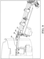
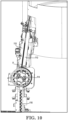
- FIGS 1-15 An automated machine 100 for organizing and feeding cylindrical products will now be described with reference to FIGS 1-15 .
- the machine description will correspond to the method or process by which the cylindrical objects pass through the machine as they proceed from bulk supply to the take away conveyance.
- cylindrical products (P) illustrated in the figures are bullet-type ammunition.
- other generally-cylindrical shaped products can also be handled by the disclosed machine because various shapes and sizes of components can be varied in order to adapt the machine to the alternate products.
- the products P to be processed are first loaded in bulk into the hopper 102.
- the hopper is shown in many of the figures and particularly in FIG. 6 .
- the products are then metered into a singulation device connected to the hopper.
- the product outputs from the singulation device along a conveyor 104 (e.g., FIG. 5 ) such that the average output rate meets the operator's set output speed requirement.
- the instantaneous output rate varies above and below the set output rate.
- the products P being moved along the conveyor 104 are all arranged in a single file orientation as can be seen in FIG. 5 , with some products oriented such that their large end is leading and some products oriented oppositely such that their small end is leading.
- the products complete their journey along the conveyor 104 and enter a constriction 106 at the discharge of the transfer conveyor 104. Properly sized products pass thru this constriction and are accelerated ahead by air jets within the constriction. Products that are too large or that are misshapen to pass through the construction are stopped by the constriction and are automatically removed from the line by the machine.
- the products P successfully passing through the restriction 106 next transfer to a chute 108 which includes air jets from the bottom of the chute which act as air bearings for the cute to provide free flow of product.
- the products P then transfer from the chute 108 to gap defined between a pair of elongated rollers 110.
- These rollers spin in opposing directions at identical speeds.
- the rollers are mounted such that their longitudinal axis extends at a downward angle to define a sloped path such as can be appreciated from FIG. 4 .
- the gap dimension between the rollers 110 is finely adjusted so that the small diameter end of the product P can pass between the rollers but the large diameter end cannot.
- the aforementioned spacing between consecutive products proceeding through the roller section 110 is useful to allow each individual product to freely swing as it travels along the rollers so that the small end of the product is facing downward as the product proceeds forward in the gap between the rollers.
- the combination of the upward rotation of the rollers and the downward inclination (slope) of the rollers propels the product toward a discharge end 111 of the roller section 110.
- the now consistently-oriented products traveling across the rollers surge against one another at the discharge end 111.
- the rollers are of a sufficient length to allow the upstream end of the product queue to move upstream and downstream in response to a varying discharge rate of the singulation device. This provides a buffer between the variable input rate and the constant discharge rate of the roller assembly 110.
- Flow of product P into and out of the various stages of the machine 100 is monitored by a plurality of optical sensors 113. These sensors are coupled to computer controls that automatically adjust machine operating parameters, such as conveyor speed for example, to ensure maximized consistent flow of product through the machine 100.
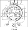
- the products P next transfer from the rollers 110 into individual pockets 112 formed in the perimeter of a miter wheel assembly 114.
- the miter wheel 114 rotates at a fixed speed to carry product from the roller assembly 110 to an accumulation device.
- the form of the wheel 114 is a truncated cone as can be seen best in FIGS. 4 and 12 .
- the cone angle is such that the surface of the pockets is oriented parallel to the product axis at the transition from the roller assembly 110 and oriented horizontal at the discharge position 180° in rotation opposite the intake point.
- the product P is carried through the miter wheel 114 assembly at a constant rate.
- the miter wheel 114 is coupled to the drive flange of a motor 116 via magnetic holding clamps 118.
- the magnetic attraction force between the drive flange and the magnetic holding clamps 118 is applied or removed by rotating the control knobs 119 atop the clamps 118.
- the magnetic attractive force between the friction surfaces on the miter wheel 114 and on the drive flange results in sufficient torque being transferred to rotate the miter wheel 114 in normal running conditions, but slippage will occur in the event of a jam condition.
- the magnetic holding clamps 118 provide both a convenient miter wheel mounting means as well as overload/jam protection.
- the products P next transfer from the miter wheel assembly 114 to the input of a vertical accumulation chamber 120 (e.g., FIGS. 3 and 13 ).
- the product path 121 through the vertical accumulation chamber is zig-zag and along the vertical axis and laid out so that product's axis cannot rotate beyond approximately 45° from horizontal, thus providing smooth product flow and maintaining consistent product orientation.
- the product path through the vertical accumulation chamber 120 is of a length that allows the upstream end of the product queue to move upstream and downstream in response to varying rate of the take away device 122.
- Flow of product into and out of the vertical accumulation chamber 120 is also controlled by level monitoring optical sensors 124 coupled to the machine's computer control system.
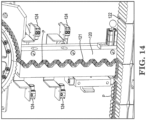
- Product is transferred from the vertical accumulation chamber to a scalloped take away conveyance 122 (e.g., FIGS. 3 and 13-15 ) and which moves regularly in a move and dwell fashion under the output of the accumulation chamber 120.
- Product is removed from the accumulation chamber 120 when the take away conveyance 122 is in motion.
- the take away conveyance 122 can define a series of side-by-side channels 126 to prevent the product P from changing orientations and to keep a consistent spacing.
- the device and method described herein advantageously control product movement in each of the elements of the device.
- the device is tolerant of product to product variation and does not dependent on tightly toleranced features.
- the machine features establish and maintain correct product orientation and minimize the likelihood of jams.
- the machine and method are thus able to be run at far higher product output speeds (e.g. 300-600 products per minute) than conventional systems.
Landscapes
- Engineering & Computer Science (AREA)
- Mechanical Engineering (AREA)
- General Engineering & Computer Science (AREA)
- Manufacturing & Machinery (AREA)
- Feeding Of Articles To Conveyors (AREA)
Claims (14)
- Machine automatisée pour l'organisation et le chargement de produits cylindriques, comprenant :une trémie (102) avec un dispositif d'individualisation disposé en aval de la trémie (102) ;un convoyeur (104) disposé en aval de la trémie (102) et du dispositif de sélection ;une paire de rouleaux allongés (110) disposés en aval du convoyeur (104),dans laquelle la paire de rouleaux (110) définit une dimension d'espace latéral entre la paire de rouleaux,dans laquelle la dimension de l'espace latéral entre la paire de rouleaux (110) est telle qu'une extrémité de petit diamètre des produits cylindriques (P) peut passer à travers l'espace mais qu'une extrémité opposée plus grande des produits cylindriques (P) ne peut pas passer à travers l'espace, permettant ainsi à chaque produit cylindrique individuel (P) d'osciller librement lorsqu'il se déplace le long des rouleaux (110) de sorte que la petite extrémité est orientée vers le bas lorsque le produit (P) avance longitudinalement le long de la paire de rouleaux (110) ;caractérisé en ce que :une roue conique (114) est disposée en aval de la paire de rouleaux allongés (110) afin de modifier l'orientation des produits cylindriques d'un alignement vertical à un alignement horizontal ;
etune chambre d'accumulation verticale (120) est positionnée pour recevoir une pluralité de produits cylindriques qui sortent de la roue conique (114), dans laquelle la chambre d'accumulation verticale (120) comprend une sortie. - Machine automatisée de la revendication 1, dans laquelle les produits cylindriques (P) sont des munitions à balles.
- Machine automatisée de la revendication 1, dans laquelle une vitesse du convoyeur (104) est variable pour conférer un espacement entre les produits cylindriques individuels (P) au fur et à mesure que les produits cylindriques (P) sont introduits dans le convoyeur (104).
- Machine automatisée de la revendication 1, comprenant en outre un étranglement (106) disposé entre le convoyeur (104) et la paire de rouleaux allongés, dans lequel l'étranglement (106) est dimensionné et formé de telle sorte que les produits cylindriques (P) tombant dans une plage dimensionnelle prédéterminée passent à travers l'étranglement (106) et sont accélérés vers l'avant par un jet d'air fourni à l'étranglement tandis que les produits cylindriques (P) qui sont plus grands que la plage dimensionnelle prédéterminée sont stoppés par l'étranglement.
- Machine automatisée de la revendication 4, comprenant en outre une goulotte (108) disposée en aval de la constriction (106) qui fait transiter les produits cylindriques (P) passant à travers la constriction (106) vers la paire de rouleaux (110).
- Machine automatisée de la revendication 1, dans laquelle la paire de rouleaux (110) est inclinée verticalement vers le bas à partir du convoyeur (104) le long d'un axe longitudinal de la paire de rouleaux (110).
- Machine automatisée de la revendication 1, dans laquelle chaque rouleau (110) de la paire de rouleaux tourne dans un sens opposé l'un à l'autre pour transmettre une force vers le haut sur les produits cylindriques (P).
- Machine automatisée de la revendication 1, comprenant en outre une pluralité de capteurs optiques (113) disposés dans toute la machine automatisée pour surveiller le flux des produits cylindriques (P) à travers la machine automatisée, dans laquelle la pluralité de capteurs optiques (113) sont couplés à un dispositif informatique qui ajuste automatiquement un ou plusieurs paramètres de fonctionnement de la machine automatisée.
- Machine automatisée de la revendication 1, dans laquelle la roue conique (114) définit une pluralité de poches individuelles (112) dans une surface de périmètre de la roue conique (114).
- Machine automatisée de la revendication 9, dans laquelle la roue conique (114) est orientée transversalement à la fois à la paire de rouleaux (110) et à la chambre d'accumulation verticale (120), et dans laquelle la roue conique (114) comprend une section d'un cône tronqué avec un angle de cône tel que les produits cylindriques (P) sont en transition par un demi-tour de la roue conique d'une orientation verticale lorsque les produits cylindriques (P) sortent de la paire de rouleaux (110) à une orientation horizontale lorsque les produits cylindriques (P) sont déchargés dans la chambre d'accumulation verticale (120).
- Machine automatisée de la revendication 1, dans laquelle la roue conique (114) est couplée à une bride d'entraînement d'un moteur (116) par l'intermédiaire d'une pince de maintien magnétique (118).
- Machine automatisée de la revendication 11, dans laquelle une force d'attraction magnétique entre la bride d'entraînement et la pince de maintien magnétique (118) est appliquée ou supprimée par un bouton de commande (119) disposé au sommet de la pince de maintien magnétique (118), et dans laquelle la force d'attraction magnétique entre la pince de maintien magnétique (118) et la bride d'entraînement est telle qu'il n'y a pas de glissement de la roue conique (114) dans des conditions de fonctionnement normales, mais qu'un glissement se produira en cas de condition de blocage rencontrée par la roue conique (114).
- Machine automatisée de la revendication 1, dans laquelle un chemin de produit (121) défini à travers la chambre d'accumulation verticale (120) est en zig-zag et le long d'un axe vertical.
- Machine automatisée de la revendication 1, comprenant en outre un convoyeur d'évacuation (122) disposé à côté de la sortie de la chambre d'accumulation verticale (120), le convoyeur d'évacuation (122) définissant une pluralité de festons (126) pour bercer le produit cylindrique (P) dans un arrangement côte à côte lorsque le produit cylindrique (P) sort de la chambre d'accumulation verticale (120).
Applications Claiming Priority (2)
| Application Number | Priority Date | Filing Date | Title |
|---|---|---|---|
| US201962881932P | 2019-08-01 | 2019-08-01 | |
| PCT/US2020/044668 WO2021022233A1 (fr) | 2019-08-01 | 2020-07-31 | Système et procédé d'organisation et de chargement de produits cylindriques d'un approvisionnement en vrac à un moyen de transport et d'enlèvement de produits |
Publications (3)
| Publication Number | Publication Date |
|---|---|
| EP4007884A1 EP4007884A1 (fr) | 2022-06-08 |
| EP4007884A4 EP4007884A4 (fr) | 2023-08-30 |
| EP4007884B1 true EP4007884B1 (fr) | 2025-02-19 |
Family
ID=74230638
Family Applications (1)
| Application Number | Title | Priority Date | Filing Date |
|---|---|---|---|
| EP20847908.9A Active EP4007884B1 (fr) | 2019-08-01 | 2020-07-31 | Machine automatisée pour l'organisation et l'alimentation de produits cylindriques |
Country Status (3)
| Country | Link |
|---|---|
| US (1) | US11548736B2 (fr) |
| EP (1) | EP4007884B1 (fr) |
| WO (1) | WO2021022233A1 (fr) |
Families Citing this family (1)
| Publication number | Priority date | Publication date | Assignee | Title |
|---|---|---|---|---|
| JP7586475B2 (ja) * | 2020-11-24 | 2024-11-19 | 電元社トーア株式会社 | ボルト切出し装置 |
Citations (1)
| Publication number | Priority date | Publication date | Assignee | Title |
|---|---|---|---|---|
| US4881447A (en) * | 1988-05-27 | 1989-11-21 | Teleflex Incorporated | Round-orienting replenisher for ammunition storage and transport system |
Family Cites Families (18)
| Publication number | Priority date | Publication date | Assignee | Title |
|---|---|---|---|---|
| US2403862A (en) * | 1942-04-20 | 1946-07-09 | Eino E Lakso | Article delivering apparatus |
| US2377431A (en) * | 1942-08-24 | 1945-06-05 | Eino E Lakso | Article handling machine |
| US3942645A (en) * | 1969-06-26 | 1976-03-09 | Eli Lilly And Company | Feeding and rectifying apparatus and method |
| US3635325A (en) * | 1969-11-24 | 1972-01-18 | Pneumatic Scale Corp | Closure-handling apparatus |
| US4122933A (en) * | 1977-04-04 | 1978-10-31 | Starzyk Eugene J | Feeder transfer chute |
| US4137820A (en) * | 1977-12-09 | 1979-02-06 | Tesseract Corporation | Ammunition handling and loading system |
| US4312438A (en) * | 1978-03-27 | 1982-01-26 | Vatsvog Marlo K | Bullet alignment apparatus |
| US4223778A (en) * | 1978-05-12 | 1980-09-23 | Owens-Illinois, Inc. | Parison handling assemblies and methods for handling parisons |
| US4457209A (en) | 1980-08-27 | 1984-07-03 | Fmc Corporation | Automated large caliber ammunition handling system |
| US4549662A (en) * | 1982-03-25 | 1985-10-29 | General Electric Company | Transport apparatus |
| FR2556273B1 (fr) | 1983-12-09 | 1986-07-25 | Pont A Mousson | Procede de fabrication de bouteilles en matiere plastique a partir d'ebauches et ebauche obtenue a partir de ce procede |
| US4717026A (en) * | 1986-04-03 | 1988-01-05 | Golden Aluminum Company | Container scanning and accounting device |
| EP1006332B1 (fr) | 1998-12-04 | 2001-06-13 | Oerlikon Contraves Ag | Dispositif d'alimentation en munitions pour un canon |
| FR2864050B1 (fr) * | 2003-12-23 | 2007-04-06 | Sidel Sa | Systeme d'alimentation de preformes comportant un dispositif d'elimination selective des preformes mal positionnees de type allonge |
| CH699223A1 (de) * | 2008-07-17 | 2010-01-29 | M Tanner Ag | Vorrichtung und Verfahren zum Vereinzeln von zylindrischen Körpern. |
| US8661959B2 (en) * | 2011-11-23 | 2014-03-04 | Richard Koskela | Bullet-orienting system |
| DE102015205984A1 (de) * | 2015-04-02 | 2016-10-06 | Krones Aktiengesellschaft | Verfahren und Führungssystem für den Transport von Behältern oder Behälter-komponenten in Industrieanlagen für die Behälterherstellung und/oder Produktabfüllung |
| US11226186B2 (en) * | 2019-01-17 | 2022-01-18 | CK Manufacturing, LLC | Configurable ammunition packaging apparatus |
-
2020
- 2020-07-31 US US16/945,760 patent/US11548736B2/en active Active
- 2020-07-31 EP EP20847908.9A patent/EP4007884B1/fr active Active
- 2020-07-31 WO PCT/US2020/044668 patent/WO2021022233A1/fr not_active Ceased
Patent Citations (1)
| Publication number | Priority date | Publication date | Assignee | Title |
|---|---|---|---|---|
| US4881447A (en) * | 1988-05-27 | 1989-11-21 | Teleflex Incorporated | Round-orienting replenisher for ammunition storage and transport system |
Also Published As
| Publication number | Publication date |
|---|---|
| WO2021022233A1 (fr) | 2021-02-04 |
| US11548736B2 (en) | 2023-01-10 |
| WO2021022233A9 (fr) | 2024-11-21 |
| EP4007884A4 (fr) | 2023-08-30 |
| EP4007884A1 (fr) | 2022-06-08 |
| US20210032048A1 (en) | 2021-02-04 |
Similar Documents
| Publication | Publication Date | Title |
|---|---|---|
| US10858199B2 (en) | Conveying system with segments and method for transporting individual items | |
| US4039074A (en) | Unscrambler for randomly arranged packages | |
| US7311191B2 (en) | Conveyor system for singulating and orienting | |
| CA2365287C (fr) | Transporteur de positionnement et d'alignement | |
| US20160031657A1 (en) | Singulator | |
| US11040831B2 (en) | Dual conveyor sorting system | |
| US11548736B2 (en) | System and method for organizing and feeding cylindrical products from a bulk supply to a product take away conveyance | |
| CN114476613A (zh) | 一种单件分离系统、分拣设备及其分拣方法 | |
| CN211488602U (zh) | 物料分离设备及物料投放系统 | |
| AU2004203812B2 (en) | Method and device for the conversion of a conveyed stream of flat articles | |
| JP7127627B2 (ja) | 分岐設備 | |
| JP5193387B1 (ja) | 整列搬送装置 | |
| US3834517A (en) | High speed container orienting mechanism | |
| CN110756442B (zh) | 物料分离设备及物料投放系统 | |
| US12486119B2 (en) | Apparatus for orienting or rotating objects | |
| US3403771A (en) | Container orienting mechanism | |
| JPS6236932B2 (fr) | ||
| US10435250B2 (en) | Transverse conveyors | |
| US1196048A (en) | Eewjt h | |
| WO2009065409A1 (fr) | Système d'alimentation pour l'alignement d'objets, tels que des paquets | |
| EP3292369B1 (fr) | Système de séparation de cartouche de fusil de chasse vide | |
| WO2024234398A1 (fr) | Machine de séparation et de tri à emballage unique pour grands emballages |
Legal Events
| Date | Code | Title | Description |
|---|---|---|---|
| STAA | Information on the status of an ep patent application or granted ep patent |
Free format text: STATUS: THE INTERNATIONAL PUBLICATION HAS BEEN MADE |
|
| PUAI | Public reference made under article 153(3) epc to a published international application that has entered the european phase |
Free format text: ORIGINAL CODE: 0009012 |
|
| STAA | Information on the status of an ep patent application or granted ep patent |
Free format text: STATUS: REQUEST FOR EXAMINATION WAS MADE |
|
| 17P | Request for examination filed |
Effective date: 20220214 |
|
| AK | Designated contracting states |
Kind code of ref document: A1 Designated state(s): AL AT BE BG CH CY CZ DE DK EE ES FI FR GB GR HR HU IE IS IT LI LT LU LV MC MK MT NL NO PL PT RO RS SE SI SK SM TR |
|
| DAV | Request for validation of the european patent (deleted) | ||
| DAX | Request for extension of the european patent (deleted) | ||
| A4 | Supplementary search report drawn up and despatched |
Effective date: 20230728 |
|
| RIC1 | Information provided on ipc code assigned before grant |
Ipc: F42B 33/00 20060101ALI20230724BHEP Ipc: B65G 11/08 20060101ALI20230724BHEP Ipc: B65G 29/02 20060101ALI20230724BHEP Ipc: B65G 47/24 20060101ALI20230724BHEP Ipc: B65G 35/00 20060101ALI20230724BHEP Ipc: B65G 47/14 20060101ALI20230724BHEP Ipc: B65G 37/00 20060101ALI20230724BHEP Ipc: F41A 9/04 20060101ALI20230724BHEP Ipc: F41A 9/82 20060101AFI20230724BHEP |
|
| GRAP | Despatch of communication of intention to grant a patent |
Free format text: ORIGINAL CODE: EPIDOSNIGR1 |
|
| STAA | Information on the status of an ep patent application or granted ep patent |
Free format text: STATUS: GRANT OF PATENT IS INTENDED |
|
| INTG | Intention to grant announced |
Effective date: 20240729 |
|
| GRAJ | Information related to disapproval of communication of intention to grant by the applicant or resumption of examination proceedings by the epo deleted |
Free format text: ORIGINAL CODE: EPIDOSDIGR1 |
|
| STAA | Information on the status of an ep patent application or granted ep patent |
Free format text: STATUS: REQUEST FOR EXAMINATION WAS MADE |
|
| INTC | Intention to grant announced (deleted) | ||
| GRAS | Grant fee paid |
Free format text: ORIGINAL CODE: EPIDOSNIGR3 |
|
| STAA | Information on the status of an ep patent application or granted ep patent |
Free format text: STATUS: GRANT OF PATENT IS INTENDED |
|
| GRAP | Despatch of communication of intention to grant a patent |
Free format text: ORIGINAL CODE: EPIDOSNIGR1 |
|
| INTG | Intention to grant announced |
Effective date: 20241213 |
|
| GRAA | (expected) grant |
Free format text: ORIGINAL CODE: 0009210 |
|
| STAA | Information on the status of an ep patent application or granted ep patent |
Free format text: STATUS: THE PATENT HAS BEEN GRANTED |
|
| AK | Designated contracting states |
Kind code of ref document: B1 Designated state(s): AL AT BE BG CH CY CZ DE DK EE ES FI FR GB GR HR HU IE IS IT LI LT LU LV MC MK MT NL NO PL PT RO RS SE SI SK SM TR |
|
| REG | Reference to a national code |
Ref country code: GB Ref legal event code: FG4D |
|
| REG | Reference to a national code |
Ref country code: CH Ref legal event code: EP |
|
| REG | Reference to a national code |
Ref country code: IE Ref legal event code: FG4D |
|
| REG | Reference to a national code |
Ref country code: DE Ref legal event code: R096 Ref document number: 602020046490 Country of ref document: DE |
|
| REG | Reference to a national code |
Ref country code: NL Ref legal event code: MP Effective date: 20250219 |
|
| PG25 | Lapsed in a contracting state [announced via postgrant information from national office to epo] |
Ref country code: RS Free format text: LAPSE BECAUSE OF FAILURE TO SUBMIT A TRANSLATION OF THE DESCRIPTION OR TO PAY THE FEE WITHIN THE PRESCRIBED TIME-LIMIT Effective date: 20250519 |
|
| PG25 | Lapsed in a contracting state [announced via postgrant information from national office to epo] |
Ref country code: FI Free format text: LAPSE BECAUSE OF FAILURE TO SUBMIT A TRANSLATION OF THE DESCRIPTION OR TO PAY THE FEE WITHIN THE PRESCRIBED TIME-LIMIT Effective date: 20250219 |
|
| PG25 | Lapsed in a contracting state [announced via postgrant information from national office to epo] |
Ref country code: PL Free format text: LAPSE BECAUSE OF FAILURE TO SUBMIT A TRANSLATION OF THE DESCRIPTION OR TO PAY THE FEE WITHIN THE PRESCRIBED TIME-LIMIT Effective date: 20250219 |
|
| PG25 | Lapsed in a contracting state [announced via postgrant information from national office to epo] |
Ref country code: ES Free format text: LAPSE BECAUSE OF FAILURE TO SUBMIT A TRANSLATION OF THE DESCRIPTION OR TO PAY THE FEE WITHIN THE PRESCRIBED TIME-LIMIT Effective date: 20250219 |
|
| REG | Reference to a national code |
Ref country code: LT Ref legal event code: MG9D |
|
| PG25 | Lapsed in a contracting state [announced via postgrant information from national office to epo] |
Ref country code: NO Free format text: LAPSE BECAUSE OF FAILURE TO SUBMIT A TRANSLATION OF THE DESCRIPTION OR TO PAY THE FEE WITHIN THE PRESCRIBED TIME-LIMIT Effective date: 20250519 Ref country code: IS Free format text: LAPSE BECAUSE OF FAILURE TO SUBMIT A TRANSLATION OF THE DESCRIPTION OR TO PAY THE FEE WITHIN THE PRESCRIBED TIME-LIMIT Effective date: 20250619 |
|
| PG25 | Lapsed in a contracting state [announced via postgrant information from national office to epo] |
Ref country code: NL Free format text: LAPSE BECAUSE OF FAILURE TO SUBMIT A TRANSLATION OF THE DESCRIPTION OR TO PAY THE FEE WITHIN THE PRESCRIBED TIME-LIMIT Effective date: 20250219 |
|
| PG25 | Lapsed in a contracting state [announced via postgrant information from national office to epo] |
Ref country code: HR Free format text: LAPSE BECAUSE OF FAILURE TO SUBMIT A TRANSLATION OF THE DESCRIPTION OR TO PAY THE FEE WITHIN THE PRESCRIBED TIME-LIMIT Effective date: 20250219 |
|
| PG25 | Lapsed in a contracting state [announced via postgrant information from national office to epo] |
Ref country code: PT Free format text: LAPSE BECAUSE OF FAILURE TO SUBMIT A TRANSLATION OF THE DESCRIPTION OR TO PAY THE FEE WITHIN THE PRESCRIBED TIME-LIMIT Effective date: 20250620 Ref country code: LV Free format text: LAPSE BECAUSE OF FAILURE TO SUBMIT A TRANSLATION OF THE DESCRIPTION OR TO PAY THE FEE WITHIN THE PRESCRIBED TIME-LIMIT Effective date: 20250219 |
|
| PG25 | Lapsed in a contracting state [announced via postgrant information from national office to epo] |
Ref country code: GR Free format text: LAPSE BECAUSE OF FAILURE TO SUBMIT A TRANSLATION OF THE DESCRIPTION OR TO PAY THE FEE WITHIN THE PRESCRIBED TIME-LIMIT Effective date: 20250520 Ref country code: BG Free format text: LAPSE BECAUSE OF FAILURE TO SUBMIT A TRANSLATION OF THE DESCRIPTION OR TO PAY THE FEE WITHIN THE PRESCRIBED TIME-LIMIT Effective date: 20250219 |
|
| REG | Reference to a national code |
Ref country code: AT Ref legal event code: MK05 Ref document number: 1768624 Country of ref document: AT Kind code of ref document: T Effective date: 20250219 |
|
| PG25 | Lapsed in a contracting state [announced via postgrant information from national office to epo] |
Ref country code: SE Free format text: LAPSE BECAUSE OF FAILURE TO SUBMIT A TRANSLATION OF THE DESCRIPTION OR TO PAY THE FEE WITHIN THE PRESCRIBED TIME-LIMIT Effective date: 20250219 |
|
| PG25 | Lapsed in a contracting state [announced via postgrant information from national office to epo] |
Ref country code: SM Free format text: LAPSE BECAUSE OF FAILURE TO SUBMIT A TRANSLATION OF THE DESCRIPTION OR TO PAY THE FEE WITHIN THE PRESCRIBED TIME-LIMIT Effective date: 20250219 |
|
| PG25 | Lapsed in a contracting state [announced via postgrant information from national office to epo] |
Ref country code: DK Free format text: LAPSE BECAUSE OF FAILURE TO SUBMIT A TRANSLATION OF THE DESCRIPTION OR TO PAY THE FEE WITHIN THE PRESCRIBED TIME-LIMIT Effective date: 20250219 |
|
| PG25 | Lapsed in a contracting state [announced via postgrant information from national office to epo] |
Ref country code: IT Free format text: LAPSE BECAUSE OF FAILURE TO SUBMIT A TRANSLATION OF THE DESCRIPTION OR TO PAY THE FEE WITHIN THE PRESCRIBED TIME-LIMIT Effective date: 20250219 |
|
| PG25 | Lapsed in a contracting state [announced via postgrant information from national office to epo] |
Ref country code: AT Free format text: LAPSE BECAUSE OF FAILURE TO SUBMIT A TRANSLATION OF THE DESCRIPTION OR TO PAY THE FEE WITHIN THE PRESCRIBED TIME-LIMIT Effective date: 20250219 |
|
| PG25 | Lapsed in a contracting state [announced via postgrant information from national office to epo] |
Ref country code: EE Free format text: LAPSE BECAUSE OF FAILURE TO SUBMIT A TRANSLATION OF THE DESCRIPTION OR TO PAY THE FEE WITHIN THE PRESCRIBED TIME-LIMIT Effective date: 20250219 Ref country code: CZ Free format text: LAPSE BECAUSE OF FAILURE TO SUBMIT A TRANSLATION OF THE DESCRIPTION OR TO PAY THE FEE WITHIN THE PRESCRIBED TIME-LIMIT Effective date: 20250219 |
|
| PG25 | Lapsed in a contracting state [announced via postgrant information from national office to epo] |
Ref country code: RO Free format text: LAPSE BECAUSE OF FAILURE TO SUBMIT A TRANSLATION OF THE DESCRIPTION OR TO PAY THE FEE WITHIN THE PRESCRIBED TIME-LIMIT Effective date: 20250219 |
|
| PG25 | Lapsed in a contracting state [announced via postgrant information from national office to epo] |
Ref country code: SK Free format text: LAPSE BECAUSE OF FAILURE TO SUBMIT A TRANSLATION OF THE DESCRIPTION OR TO PAY THE FEE WITHIN THE PRESCRIBED TIME-LIMIT Effective date: 20250219 |
|
| REG | Reference to a national code |
Ref country code: DE Ref legal event code: R097 Ref document number: 602020046490 Country of ref document: DE |
|
| PLBE | No opposition filed within time limit |
Free format text: ORIGINAL CODE: 0009261 |
|
| STAA | Information on the status of an ep patent application or granted ep patent |
Free format text: STATUS: NO OPPOSITION FILED WITHIN TIME LIMIT |
|
| REG | Reference to a national code |
Ref country code: CH Ref legal event code: L10 Free format text: ST27 STATUS EVENT CODE: U-0-0-L10-L00 (AS PROVIDED BY THE NATIONAL OFFICE) Effective date: 20251231 |
|
| 26N | No opposition filed |
Effective date: 20251120 |
|
| REG | Reference to a national code |
Ref country code: DE Ref legal event code: R119 Ref document number: 602020046490 Country of ref document: DE |
|
| REG | Reference to a national code |
Ref country code: CH Ref legal event code: H13 Free format text: ST27 STATUS EVENT CODE: U-0-0-H10-H13 (AS PROVIDED BY THE NATIONAL OFFICE) Effective date: 20260224 |
|
| PG25 | Lapsed in a contracting state [announced via postgrant information from national office to epo] |
Ref country code: LU Free format text: LAPSE BECAUSE OF NON-PAYMENT OF DUE FEES Effective date: 20250731 |
|
| GBPC | Gb: european patent ceased through non-payment of renewal fee |
Effective date: 20250731 |
|
| REG | Reference to a national code |
Ref country code: BE Ref legal event code: MM Effective date: 20250731 |
|
| PG25 | Lapsed in a contracting state [announced via postgrant information from national office to epo] |
Ref country code: GB Free format text: LAPSE BECAUSE OF NON-PAYMENT OF DUE FEES Effective date: 20250731 |
|
| PG25 | Lapsed in a contracting state [announced via postgrant information from national office to epo] |
Ref country code: DE Free format text: LAPSE BECAUSE OF NON-PAYMENT OF DUE FEES Effective date: 20260203 |
|
| PG25 | Lapsed in a contracting state [announced via postgrant information from national office to epo] |
Ref country code: BE Free format text: LAPSE BECAUSE OF NON-PAYMENT OF DUE FEES Effective date: 20250731 |
|
| PG25 | Lapsed in a contracting state [announced via postgrant information from national office to epo] |
Ref country code: FR Free format text: LAPSE BECAUSE OF NON-PAYMENT OF DUE FEES Effective date: 20250731 |
|
| PG25 | Lapsed in a contracting state [announced via postgrant information from national office to epo] |
Ref country code: CH Free format text: LAPSE BECAUSE OF NON-PAYMENT OF DUE FEES Effective date: 20250731 |