EP4008291A1 - Brosse à dents électrique à mouvement complexe - Google Patents
Brosse à dents électrique à mouvement complexe Download PDFInfo
- Publication number
- EP4008291A1 EP4008291A1 EP21212396.2A EP21212396A EP4008291A1 EP 4008291 A1 EP4008291 A1 EP 4008291A1 EP 21212396 A EP21212396 A EP 21212396A EP 4008291 A1 EP4008291 A1 EP 4008291A1
- Authority
- EP
- European Patent Office
- Prior art keywords
- rotation
- axis
- bristle
- outer gear
- bristle head
- Prior art date
- Legal status (The legal status is an assumption and is not a legal conclusion. Google has not performed a legal analysis and makes no representation as to the accuracy of the status listed.)
- Granted
Links
Images


Classifications
-
- A—HUMAN NECESSITIES
- A61—MEDICAL OR VETERINARY SCIENCE; HYGIENE
- A61C—DENTISTRY; APPARATUS OR METHODS FOR ORAL OR DENTAL HYGIENE
- A61C17/00—Devices for cleaning, polishing, rinsing or drying teeth, teeth cavities or prostheses; Saliva removers; Dental appliances for receiving spittle
- A61C17/16—Power-driven cleaning or polishing devices
- A61C17/22—Power-driven cleaning or polishing devices with brushes, cushions, cups, or the like
- A61C17/32—Power-driven cleaning or polishing devices with brushes, cushions, cups, or the like reciprocating or oscillating
- A61C17/34—Power-driven cleaning or polishing devices with brushes, cushions, cups, or the like reciprocating or oscillating driven by electric motor
- A61C17/3409—Power-driven cleaning or polishing devices with brushes, cushions, cups, or the like reciprocating or oscillating driven by electric motor characterized by the movement of the brush body
- A61C17/3472—Power-driven cleaning or polishing devices with brushes, cushions, cups, or the like reciprocating or oscillating driven by electric motor characterized by the movement of the brush body with combined movements of the brush body
-
- A—HUMAN NECESSITIES
- A61—MEDICAL OR VETERINARY SCIENCE; HYGIENE
- A61C—DENTISTRY; APPARATUS OR METHODS FOR ORAL OR DENTAL HYGIENE
- A61C17/00—Devices for cleaning, polishing, rinsing or drying teeth, teeth cavities or prostheses; Saliva removers; Dental appliances for receiving spittle
- A61C17/16—Power-driven cleaning or polishing devices
- A61C17/22—Power-driven cleaning or polishing devices with brushes, cushions, cups, or the like
-
- A—HUMAN NECESSITIES
- A61—MEDICAL OR VETERINARY SCIENCE; HYGIENE
- A61C—DENTISTRY; APPARATUS OR METHODS FOR ORAL OR DENTAL HYGIENE
- A61C17/00—Devices for cleaning, polishing, rinsing or drying teeth, teeth cavities or prostheses; Saliva removers; Dental appliances for receiving spittle
- A61C17/16—Power-driven cleaning or polishing devices
- A61C17/22—Power-driven cleaning or polishing devices with brushes, cushions, cups, or the like
- A61C17/24—Power-driven cleaning or polishing devices with brushes, cushions, cups, or the like rotating continuously
-
- A—HUMAN NECESSITIES
- A61—MEDICAL OR VETERINARY SCIENCE; HYGIENE
- A61C—DENTISTRY; APPARATUS OR METHODS FOR ORAL OR DENTAL HYGIENE
- A61C17/00—Devices for cleaning, polishing, rinsing or drying teeth, teeth cavities or prostheses; Saliva removers; Dental appliances for receiving spittle
- A61C17/16—Power-driven cleaning or polishing devices
- A61C17/22—Power-driven cleaning or polishing devices with brushes, cushions, cups, or the like
- A61C17/24—Power-driven cleaning or polishing devices with brushes, cushions, cups, or the like rotating continuously
- A61C17/26—Power-driven cleaning or polishing devices with brushes, cushions, cups, or the like rotating continuously driven by electric motor
-
- A—HUMAN NECESSITIES
- A61—MEDICAL OR VETERINARY SCIENCE; HYGIENE
- A61C—DENTISTRY; APPARATUS OR METHODS FOR ORAL OR DENTAL HYGIENE
- A61C17/00—Devices for cleaning, polishing, rinsing or drying teeth, teeth cavities or prostheses; Saliva removers; Dental appliances for receiving spittle
- A61C17/16—Power-driven cleaning or polishing devices
- A61C17/22—Power-driven cleaning or polishing devices with brushes, cushions, cups, or the like
- A61C17/32—Power-driven cleaning or polishing devices with brushes, cushions, cups, or the like reciprocating or oscillating
- A61C17/34—Power-driven cleaning or polishing devices with brushes, cushions, cups, or the like reciprocating or oscillating driven by electric motor
- A61C17/3409—Power-driven cleaning or polishing devices with brushes, cushions, cups, or the like reciprocating or oscillating driven by electric motor characterized by the movement of the brush body
- A61C17/3445—Translation along the axis of the toothbrush handle
-
- A—HUMAN NECESSITIES
- A61—MEDICAL OR VETERINARY SCIENCE; HYGIENE
- A61C—DENTISTRY; APPARATUS OR METHODS FOR ORAL OR DENTAL HYGIENE
- A61C17/00—Devices for cleaning, polishing, rinsing or drying teeth, teeth cavities or prostheses; Saliva removers; Dental appliances for receiving spittle
- A61C17/16—Power-driven cleaning or polishing devices
- A61C17/22—Power-driven cleaning or polishing devices with brushes, cushions, cups, or the like
- A61C17/40—Power-driven cleaning or polishing devices with brushes, cushions, cups, or the like orbiting, e.g. nutating
Definitions
- the present invention relates to powered toothbrushes, specifically those powered by electricity.
- Most powered toothbrushes that exist in the art comprise bristles that are used to clean a user's teeth, said bristles being connected to the toothbrush by a bristle head.
- a functionality of powered toothbrushes may be that the bristle head moves automatically.
- the motion of the bristle head is generally an oscillatory motion either along the distal-proximal axis of the toothbrush or about an axis of rotation of the bristle head. Bristle heads that move in an oscillatory manner about their axes of rotation may not be effective in cleaning teeth.
- a simple rotary motion may cause damage to a user's gums because of the greater velocity of the bristles that are placed at a greater radial distance from the center of the bristle head.
- the translations as described herein when applied to the bristle head of a powered toothbrush are more effective at cleaning a user's teeth, since the translations of the bristle head allow the bristles to reach more areas of a user's teeth and gums when the toothbrush is held in one position than if the bristle head did not oscillate.
- the translations of the bristle head also allow the bristles to contact a user's teeth and gums at different angles than if the bristle head did not translate, which allows for cleaning of areas of the user's teeth and gums that may be hard to reach with a simple oscillating toothbrush.
- a toothbrush that comprises a bristle head that not only moves in a rotary manner, but may also translate as to reduce the damage to a patient's teeth and/or gums.
- Embodiments of the present invention may comprise a powered toothbrush, which may comprise a bristle head and an outer gear. Both the bristle head and the outer gear may comprise a distal end, a proximal end, and a center.
- the powered toothbrush may further comprise a plurality of bristles, each with a distal end and a proximal end. The distal ends of each of the plurality of bristles may be connected to the proximal end of the bristle head. The distal end of the bristle head may mate with the proximal end of the outer gear.
- the outer gear may rotate about a first axis of rotation. Said first axis of rotation may run from the distal end of the outer gear to the proximal end of the outer gear through the center of the outer gear.
- the mating between the bristle head and the outer gear may cause the bristle head to orbit the first axis of rotation via one or more bristle paths while simultaneously completing one or more rotary movements about a second axis of rotation.
- the second axis of rotation may run from the distal end of the bristle head to the proximal end of the bristle head through the center of the bristle head.
- the second axis of rotation may move along the one or more bristle paths with the bristle head.
- the one or more bristle paths may be ovular-shaped. In other embodiments, the one or more bristle paths may be circular-shaped. In some embodiments, the one or more bristle paths may be located on a translation plane. The translation plane may be normal to the first axis of rotation.
- the one or more rotary movements may comprise at least one full rotation about the second axis of rotation. In those and other embodiments, the one or more rotary movements may comprise at least one partial rotation about the second axis of rotation.
- the orbiting of the bristle head about the first axis of rotation may comprise one or more 360-degree orbits.
- the bristle path may orbit anywhere in the range of 30 degrees to 360 degrees about the first axis of rotation in order to complete one full rotation about the second axis of rotation.
- the powered toothbrush may further comprise a driveshaft with a distal end and a proximal end.
- the outer gear may comprise a first bevel gear
- the distal end of the driveshaft may comprise a second bevel gear that mates with the first bevel gear.
- the first bevel gear may be located at the distal end of the outer gear.
- the outer gear may be located anywhere along a length of the outer gear, said length spanning from the distal end of the outer gear to the proximal end of the outer gear.
- the driveshaft may rotate about a third axis of rotation such that the mating between the first and second bevel gears causes the rotation of the outer gear about the first axis of rotation.
- the third axis of rotation may be perpendicular to the first axis of rotation.
- the mating between the outer gear and bristle head may be such that the distal end of the bristle head comprises a plurality of rounded gear teeth, and the proximal end of the outer gear comprises a plurality of rounded gear teeth.
- the rounded gear teeth of the outer gear may interact with the rounded gear teeth of the bristle head to cause the bristle head to orbit the first axis of rotation via the one or more bristle paths while simultaneously completing the one or more rotary movements about the second axis of rotation.
- the mating between the outer gear and bristle head may be such that the bristle head may mate with the proximal end of the outer gear such that the center of the bristle head is located an offset distance from the center of the outer gear.
- This mating between the bristle head and outer gear may allow the bristle head to rotate freely about the second axis of rotation.
- the mating between the outer gear and bristle head may cause the bristle head to orbit the first axis of rotation while simultaneously completing the one or more rotary movements about the second axis of rotation when the outer gear rotates about the first axis of rotation.
- the mating between the outer gear and bristle head may be such that the bristle head comprises a hole that runs from the distal end of the bristle head to the proximal end of the bristle head through the center of the bristle head, and the outer gear comprises a post that extends proximally from the proximal end of the outer gear. The post may be located an offset distance from the center of the outer gear.
- the hole of the bristle head may mate with the post of the outer gear such that the rotation of the outer gear about the first axis of rotation causes the bristle head to orbit the first axis of rotation via the one or more bristle paths while simultaneously completing the one or more rotary movements about the second axis of rotation.
- proximal and distal are used for the purposes of this description, a "proximal” portion of the invention is closer to a user's teeth when the invention is in use, and a “distal” portion of the invention is further from the user's teeth when the invention is in use.
- a first component being proximal to a second components means that the first component is closer to the user's teeth when the invention is in use.
- a first component being distal to a second component means that the first component is further from the user's teeth when the invention is in use.
- a component “extending distally” is extending away from a user's teeth, and a component "extending proximally” is extending towards a user's teeth.
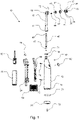
- Fig. 1 shows a perspective exploded view of a powered toothbrush 10 comprising a casing 12 with distal end 13 and a proximal end 14.
- the powered toothbrush 10 further comprises a head 16 with a distal end 17 and proximal end 18.
- the distal end 17 of the head 16 connects to the proximal end 14 of the casing 12.
- a driveshaft 46 comprising a distal end 47 and proximal end 48 is housed within the head 16 such that the distal end 47 of the driveshaft 46 is located near the distal end 17 of the head 16, and such that the proximal end 48 of the driveshaft 46 is located near the proximal end 18 of the head 16.
- the distal end 47 of the driveshaft 46 is connected to a motor 52, which is housed within the casing 12.
- the motor 52 is powered by a battery 50, which is also housed within the casing 12.
- the proximal end 48 of the driveshaft 46 is connected to a second bevel gear 44, which mates with a first bevel gear 42.
- the mating between the first bevel gear 42 and second bevel gear 44 may be in the manner in which bevel gears mate as known in the art of bevel gears.
- the first bevel gear 42 is attached to an outer gear 40.
- the first bevel gear 42 and outer gear 40 are shown as the same piece in Fig. 1 , such that the outer gear 40 comprises the first bevel gear 42 as the distal end of the outer gear 40.
- the outer gear comprises a plurality of rounded gear teeth 41 at the proximal end of the outer gear 40.
- the rounded gear teeth 41 are shown as a separate piece from the outer gear 40 in Fig. 1 .
- the piece that comprises the rounded gear teeth 41 may be attached to the outer gear 40 during assembly.
- the rounded gear teeth 41 and outer gear 40 are part of the same piece, which may also be the same piece as the first bevel gear 42.
- the rounded gear teeth 41 mate with a distal end 31 of a bristle head 30.
- the distal end 31 of the bristle head 30 may comprise rounded gear teeth similar to the rounded gear teeth 41 of the outer gear, such that rotation of the rounded gear teeth 41 of the outer gear causes rotation of the bristle head 30.
- the bristle head further comprises a proximal end 32, on which a plurality of bristles 34 are attached.
- the bristles each comprise a distal end 35 that is attached to the proximal end 32 of the bristle head, and a proximal end 36 that contacts a user's teeth when the user uses the powered toothbrush 10 to brush their teeth.
- the distal end 13 of the casing 12 is connected to a lid 20 which serves as a cover for the distal end 13 of the casing 12.
- the connection between the casing 12 and lid 20 is sealed with an o-ring 71, which is enclosed within the casing-lid connection when the powered toothbrush 10 is assembled.
- the powered toothbrush 10 also comprises another o-ring 71 that seals the connection between the casing 12 and the head 16.
- the invention may comprise any number of other o-rings not shown in Fig. 1 .
- the lid 20 may rest on or inside of a charger (not shown in Fig. 1 ) when the powered toothbrush 10 is charging.
- the charger may induce a magnetic field, which in turn induces an electrical current through an RX coil 54 located within the casing 12.
- the RX coil 54 may be connected to the battery 50 directly or via a circuit board 60.
- the charger may charge the battery 50 by means of induction, using the RX coil 54 to induce an electrical current.
- a plurality of screws 70 used to secure various components of the powered toothbrush 10 together.
- One of said screws 70 is located near the distal end 13 of the casing 13 and is used to secure the lid 20 to the casing 12.
- a retaining ring 72 is used to secure the bristle head 30 to the head 16.
- FIG. 1 Also shown in Fig. 1 is an inner frame 24 used to support other components of the powered toothbrush 10 within the casing 12.
- the inner frame 24 may serve as the structural component to support the circuit board 60.
- the circuit board 60 comprises an LED 64 that either protrudes through the casing 12 or shines light through the casing 12 by use of a lens or hole. The LED may be used to indicate various statues of the powered toothbrush 10 such as charging, low battery, in-use, etc.
- a button 62 is connected to the circuit board and protrudes through the casing 12 in order to be able to be pressed by a user. By pressing the button, the user may switch the motor 52 and/or other components of the powered toothbrush 10 on and off by means of actuating a switch on the circuit board 60.
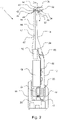
- Fig. 2 shows a right-side cross-sectional view of the powered toothbrush 10 from Fig. 1 .
- the casing 12 with its distal end 13 and proximal end 14 are shown in Fig. 2 .
- Also shown in Fig. 2 are the head 16 with its distal end 17 and proximal end 18, the lid 20, the inner frame 24, the battery 50, the motor 52, the RX coil 54, the circuit board 60, the button 62, and one of the plurality of screws 70.
- Fig. 2 shows a right-side cross-sectional view of the powered toothbrush 10 from Fig. 1 .
- the casing 12 with its distal end 13 and proximal end 14 are shown in Fig. 2 .
- Also shown in Fig. 2 are the head 16 with its distal end 17 and proximal end 18, the lid 20, the inner frame 24, the battery 50, the motor 52, the RX coil 54, the circuit board 60, the button 62, and one of the plurality of screws 70.
- the bristle head 30 with its distal end 31 and proximal end 32, the bristles 34 with their distal ends 35 and proximal ends 36, the outer gear 40 with its rounded gear teeth 41 and first bevel gear 42, the second bevel gear 44, and the driveshaft 46 with its distal end 47 and proximal end 48.
- the connections between said components are the same in Fig. 2 as described in Fig. 1 .
- the charger 22 on or in which the powered toothbrush 10 sits when it is charging.
- the charger comprises a receiving port 23 that exists as a recessed portion in which the distal end 13 of the casing 12 is placed when the powered toothbrush 10 is assembled. Placing the distal end 13 of the casing 12 inside of the receiving port 23 when the powered toothbrush 10 is assembled may cause the battery 50 to charge via induction as described previously herein.
- the charger 22 may further comprise a cord (not shown) to provide an electrical connection between the charger and an electrical outlet.
- Fig. 3 shows a top section view of the distal end 31 of the bristle head 30 mating with the rounded gear teeth 41 of the outer gear 40.
- the outer gear 40 comprises a plurality of rounded gear teeth 41 that interact with rounded gear teeth 33 of the bristle head 30. This interaction is such that when the outer gear 40 rotates in a clockwise direction, the rounded gear teeth 41 of the outer gear 40 interact with the rounded gear teeth 33 of the bristle head 30 to cause the bristle head to rotate in a clockwise direction.
- the bristle head 30 is sized appropriately so that the previously described interaction between the rounded gear teeth translates the bristle head 30 within the confines of the outer gear 40. This creates a unique bristle pattern shown and described in Fig. 4 .
- Fig. 4 shows a bristle pattern 74 comprising a plurality of bristle paths 75.
- the bristle paths 75 shown in Fig. 4 are ovular-shaped to show that the bristle head 30 may translate in a series of ovular paths while simultaneously rotating. This motion of simultaneous rotation and translation provides the benefit of enhanced teeth cleaning when the bristles 34 contact a user's teeth.
Landscapes
- Health & Medical Sciences (AREA)
- Dentistry (AREA)
- Epidemiology (AREA)
- Life Sciences & Earth Sciences (AREA)
- Animal Behavior & Ethology (AREA)
- General Health & Medical Sciences (AREA)
- Public Health (AREA)
- Veterinary Medicine (AREA)
- Brushes (AREA)
Applications Claiming Priority (2)
| Application Number | Priority Date | Filing Date | Title |
|---|---|---|---|
| US202063121191P | 2020-12-03 | 2020-12-03 | |
| US17/522,886 US12220292B2 (en) | 2020-12-03 | 2021-11-09 | Powered toothbrush with complex movement |
Publications (2)
| Publication Number | Publication Date |
|---|---|
| EP4008291A1 true EP4008291A1 (fr) | 2022-06-08 |
| EP4008291B1 EP4008291B1 (fr) | 2022-12-21 |
Family
ID=78821918
Family Applications (1)
| Application Number | Title | Priority Date | Filing Date |
|---|---|---|---|
| EP21212396.2A Active EP4008291B1 (fr) | 2020-12-03 | 2021-12-03 | Brosse à dents électrique à mouvement complexe |
Country Status (4)
| Country | Link |
|---|---|
| US (1) | US12220292B2 (fr) |
| EP (1) | EP4008291B1 (fr) |
| ES (1) | ES2937735T3 (fr) |
| PL (1) | PL4008291T3 (fr) |
Citations (3)
| Publication number | Priority date | Publication date | Assignee | Title |
|---|---|---|---|---|
| US5862558A (en) * | 1994-10-29 | 1999-01-26 | Braun Aktiengesellschaft | Brush section for an electric toothbrush |
| US5867856A (en) * | 1994-09-23 | 1999-02-09 | Braun Aktiengesellschaft | Brush section for an electric toothbrush |
| US20040231078A1 (en) * | 2003-05-23 | 2004-11-25 | Braun Phillip M. | Toothbrushes |
Family Cites Families (25)
| Publication number | Priority date | Publication date | Assignee | Title |
|---|---|---|---|---|
| US1483606A (en) * | 1923-04-02 | 1924-02-12 | Krohn John | Differential gearing |
| US1981688A (en) * | 1934-02-19 | 1934-11-20 | Conti Vincent | Electric brush for teeth and the like |
| US2960884A (en) * | 1954-11-30 | 1960-11-22 | Hill Entpr Inc | Rounded tooth tips for pointed rotoid teeth |
| US4010716A (en) * | 1974-07-12 | 1977-03-08 | Karlis Minka | Rotary engine |
| US4335480A (en) | 1980-07-30 | 1982-06-22 | Liu Poo Sung | Electric rotary toothbrush |
| US4603448A (en) | 1985-06-07 | 1986-08-05 | Mtv Associates | Rotary electric toothbrush |
| US4827552A (en) | 1988-03-14 | 1989-05-09 | Better Health Concepts, Inc. | Rotary electric toothbrush |
| JPH0685727B2 (ja) | 1989-02-18 | 1994-11-02 | パーク,サ・リョン | 回転式歯ブラシ |
| IL92720A (en) * | 1989-12-15 | 1993-02-21 | Neta Holland | Toothbrush |
| US5177826A (en) | 1990-03-16 | 1993-01-12 | Hagemann International | Rotary toothbrush |
| DE4239251A1 (de) | 1992-11-21 | 1994-05-26 | Braun Ag | Elektrische Zahnbürste mit drehbarem Borstenträger |
| US5500972A (en) * | 1994-11-07 | 1996-03-26 | Foster; David C. | Rotating back scrubber |
| US5687442A (en) * | 1996-06-07 | 1997-11-18 | Mclain; Scott S. | Random orbital power cleaner |
| DE19627752A1 (de) | 1996-07-10 | 1998-01-15 | Braun Ag | Elektrische Zahnbürste |
| US6584691B1 (en) * | 1999-10-08 | 2003-07-01 | Technology Innovations, Llc | Electric shaver having orbitally moving blades |
| DE10139286A1 (de) * | 2001-08-09 | 2003-02-27 | Lev B Levitin | Rotationskolbenmaschinen (RKM-1) mit einer Abtriebswelle |
| US6795993B2 (en) | 2002-06-03 | 2004-09-28 | Yuan Huang Lin | Rotary electric toothbrush with a swing head |
| US6813793B2 (en) | 2002-09-27 | 2004-11-09 | Colgate-Palmolive Company | Toothbrush with linear and rotary fields |
| EP2263604B1 (fr) * | 2002-10-31 | 2017-08-30 | Colgate-Palmolive Company | Brosse à dents à mouvement orbital aléatoire |
| US20110138563A1 (en) * | 2008-07-14 | 2011-06-16 | Rajinder Singh Phgura | Brush mechanism |
| US8316496B2 (en) * | 2009-09-24 | 2012-11-27 | Qasem Al-Qaffas | Dental hygiene device |
| US9138303B2 (en) | 2012-07-17 | 2015-09-22 | Hint Co., Ltd. | Rotary toothbrush |
| US8966698B2 (en) * | 2012-11-27 | 2015-03-03 | Techtronic Floor Care Technology Limited | Brush head for an electric toothbrush |
| US20160287035A1 (en) * | 2015-04-03 | 2016-10-06 | Water Pik, Inc. | Skin cleansing and massaging system |
| WO2019209970A1 (fr) * | 2018-04-24 | 2019-10-31 | Microcopy Ltd | Orbiteur de prophylaxie dentaire |
-
2021
- 2021-11-09 US US17/522,886 patent/US12220292B2/en active Active
- 2021-12-03 EP EP21212396.2A patent/EP4008291B1/fr active Active
- 2021-12-03 ES ES21212396T patent/ES2937735T3/es active Active
- 2021-12-03 PL PL21212396.2T patent/PL4008291T3/pl unknown
Patent Citations (3)
| Publication number | Priority date | Publication date | Assignee | Title |
|---|---|---|---|---|
| US5867856A (en) * | 1994-09-23 | 1999-02-09 | Braun Aktiengesellschaft | Brush section for an electric toothbrush |
| US5862558A (en) * | 1994-10-29 | 1999-01-26 | Braun Aktiengesellschaft | Brush section for an electric toothbrush |
| US20040231078A1 (en) * | 2003-05-23 | 2004-11-25 | Braun Phillip M. | Toothbrushes |
Also Published As
| Publication number | Publication date |
|---|---|
| PL4008291T3 (pl) | 2023-02-13 |
| US12220292B2 (en) | 2025-02-11 |
| EP4008291B1 (fr) | 2022-12-21 |
| US20220175505A1 (en) | 2022-06-09 |
| ES2937735T3 (es) | 2023-03-30 |
Similar Documents
| Publication | Publication Date | Title |
|---|---|---|
| US4432729A (en) | Personal health care device | |
| AU2002331978B2 (en) | Electric toothbrush with at least one brush head | |
| US6799346B2 (en) | Toothbrush with oppositely reciprocating brush heads | |
| EP0460610B1 (fr) | Brosse à dents motorisée | |
| RU2266079C2 (ru) | Электроприводная зубная щетка с трехмерным вращательным движением головки | |
| US5321865A (en) | Oral hygiene device | |
| US7266855B2 (en) | Electric toothbrush | |
| AU2002331978A1 (en) | Electric toothbrush with at least one brush head | |
| US3106732A (en) | Work-actuated rotary brush | |
| GB2352621A (en) | Electric toothbrush : drive to orbit head | |
| JPH07213343A (ja) | 個人衛生の目的で用いられるブラシ | |
| JP2009183753A (ja) | 歯ブラシ | |
| US12220292B2 (en) | Powered toothbrush with complex movement | |
| HUP0201345A2 (en) | Electric toothbrush | |
| US7331076B2 (en) | Electric tooth brush with a latitudely oscillating brush head | |
| EP4431055A1 (fr) | Appareil de nettoyage et de soins | |
| JPH07116023A (ja) | 電動歯ブラシ | |
| EP1509164B1 (fr) | Brosse a dents electrique | |
| JPS5822555A (ja) | 電気機械器具 | |
| WO2014178206A1 (fr) | Brosse à dents | |
| JPH0724128U (ja) | 電動歯ブラシの可動機構 |
Legal Events
| Date | Code | Title | Description |
|---|---|---|---|
| PUAI | Public reference made under article 153(3) epc to a published international application that has entered the european phase |
Free format text: ORIGINAL CODE: 0009012 |
|
| STAA | Information on the status of an ep patent application or granted ep patent |
Free format text: STATUS: THE APPLICATION HAS BEEN PUBLISHED |
|
| AK | Designated contracting states |
Kind code of ref document: A1 Designated state(s): AL AT BE BG CH CY CZ DE DK EE ES FI FR GB GR HR HU IE IS IT LI LT LU LV MC MK MT NL NO PL PT RO RS SE SI SK SM TR |
|
| STAA | Information on the status of an ep patent application or granted ep patent |
Free format text: STATUS: REQUEST FOR EXAMINATION WAS MADE |
|
| 17P | Request for examination filed |
Effective date: 20220603 |
|
| RBV | Designated contracting states (corrected) |
Designated state(s): AL AT BE BG CH CY CZ DE DK EE ES FI FR GB GR HR HU IE IS IT LI LT LU LV MC MK MT NL NO PL PT RO RS SE SI SK SM TR |
|
| GRAP | Despatch of communication of intention to grant a patent |
Free format text: ORIGINAL CODE: EPIDOSNIGR1 |
|
| STAA | Information on the status of an ep patent application or granted ep patent |
Free format text: STATUS: GRANT OF PATENT IS INTENDED |
|
| RIC1 | Information provided on ipc code assigned before grant |
Ipc: A61C 17/40 20060101ALI20220902BHEP Ipc: A61C 17/26 20060101ALI20220902BHEP Ipc: A61C 17/24 20060101ALI20220902BHEP Ipc: A61C 17/22 20060101AFI20220902BHEP |
|
| INTG | Intention to grant announced |
Effective date: 20221006 |
|
| GRAS | Grant fee paid |
Free format text: ORIGINAL CODE: EPIDOSNIGR3 |
|
| GRAA | (expected) grant |
Free format text: ORIGINAL CODE: 0009210 |
|
| STAA | Information on the status of an ep patent application or granted ep patent |
Free format text: STATUS: THE PATENT HAS BEEN GRANTED |
|
| AK | Designated contracting states |
Kind code of ref document: B1 Designated state(s): AL AT BE BG CH CY CZ DE DK EE ES FI FR GB GR HR HU IE IS IT LI LT LU LV MC MK MT NL NO PL PT RO RS SE SI SK SM TR |
|
| REG | Reference to a national code |
Ref country code: GB Ref legal event code: FG4D |
|
| REG | Reference to a national code |
Ref country code: CH Ref legal event code: EP |
|
| REG | Reference to a national code |
Ref country code: DE Ref legal event code: R096 Ref document number: 602021001038 Country of ref document: DE |
|
| REG | Reference to a national code |
Ref country code: AT Ref legal event code: REF Ref document number: 1538589 Country of ref document: AT Kind code of ref document: T Effective date: 20230115 |
|
| REG | Reference to a national code |
Ref country code: IE Ref legal event code: FG4D |
|
| REG | Reference to a national code |
Ref country code: NL Ref legal event code: FP |
|
| REG | Reference to a national code |
Ref country code: ES Ref legal event code: FG2A Ref document number: 2937735 Country of ref document: ES Kind code of ref document: T3 Effective date: 20230330 |
|
| REG | Reference to a national code |
Ref country code: SE Ref legal event code: TRGR Ref country code: LT Ref legal event code: MG9D |
|
| PG25 | Lapsed in a contracting state [announced via postgrant information from national office to epo] |
Ref country code: NO Free format text: LAPSE BECAUSE OF FAILURE TO SUBMIT A TRANSLATION OF THE DESCRIPTION OR TO PAY THE FEE WITHIN THE PRESCRIBED TIME-LIMIT Effective date: 20230321 Ref country code: LT Free format text: LAPSE BECAUSE OF FAILURE TO SUBMIT A TRANSLATION OF THE DESCRIPTION OR TO PAY THE FEE WITHIN THE PRESCRIBED TIME-LIMIT Effective date: 20221221 Ref country code: FI Free format text: LAPSE BECAUSE OF FAILURE TO SUBMIT A TRANSLATION OF THE DESCRIPTION OR TO PAY THE FEE WITHIN THE PRESCRIBED TIME-LIMIT Effective date: 20221221 |
|
| PG25 | Lapsed in a contracting state [announced via postgrant information from national office to epo] |
Ref country code: RS Free format text: LAPSE BECAUSE OF FAILURE TO SUBMIT A TRANSLATION OF THE DESCRIPTION OR TO PAY THE FEE WITHIN THE PRESCRIBED TIME-LIMIT Effective date: 20221221 Ref country code: LV Free format text: LAPSE BECAUSE OF FAILURE TO SUBMIT A TRANSLATION OF THE DESCRIPTION OR TO PAY THE FEE WITHIN THE PRESCRIBED TIME-LIMIT Effective date: 20221221 Ref country code: HR Free format text: LAPSE BECAUSE OF FAILURE TO SUBMIT A TRANSLATION OF THE DESCRIPTION OR TO PAY THE FEE WITHIN THE PRESCRIBED TIME-LIMIT Effective date: 20221221 Ref country code: GR Free format text: LAPSE BECAUSE OF FAILURE TO SUBMIT A TRANSLATION OF THE DESCRIPTION OR TO PAY THE FEE WITHIN THE PRESCRIBED TIME-LIMIT Effective date: 20230322 |
|
| PG25 | Lapsed in a contracting state [announced via postgrant information from national office to epo] |
Ref country code: SM Free format text: LAPSE BECAUSE OF FAILURE TO SUBMIT A TRANSLATION OF THE DESCRIPTION OR TO PAY THE FEE WITHIN THE PRESCRIBED TIME-LIMIT Effective date: 20221221 Ref country code: RO Free format text: LAPSE BECAUSE OF FAILURE TO SUBMIT A TRANSLATION OF THE DESCRIPTION OR TO PAY THE FEE WITHIN THE PRESCRIBED TIME-LIMIT Effective date: 20221221 Ref country code: PT Free format text: LAPSE BECAUSE OF FAILURE TO SUBMIT A TRANSLATION OF THE DESCRIPTION OR TO PAY THE FEE WITHIN THE PRESCRIBED TIME-LIMIT Effective date: 20230421 Ref country code: EE Free format text: LAPSE BECAUSE OF FAILURE TO SUBMIT A TRANSLATION OF THE DESCRIPTION OR TO PAY THE FEE WITHIN THE PRESCRIBED TIME-LIMIT Effective date: 20221221 Ref country code: CZ Free format text: LAPSE BECAUSE OF FAILURE TO SUBMIT A TRANSLATION OF THE DESCRIPTION OR TO PAY THE FEE WITHIN THE PRESCRIBED TIME-LIMIT Effective date: 20221221 |
|
| PG25 | Lapsed in a contracting state [announced via postgrant information from national office to epo] |
Ref country code: SK Free format text: LAPSE BECAUSE OF FAILURE TO SUBMIT A TRANSLATION OF THE DESCRIPTION OR TO PAY THE FEE WITHIN THE PRESCRIBED TIME-LIMIT Effective date: 20221221 Ref country code: IS Free format text: LAPSE BECAUSE OF FAILURE TO SUBMIT A TRANSLATION OF THE DESCRIPTION OR TO PAY THE FEE WITHIN THE PRESCRIBED TIME-LIMIT Effective date: 20230421 Ref country code: AL Free format text: LAPSE BECAUSE OF FAILURE TO SUBMIT A TRANSLATION OF THE DESCRIPTION OR TO PAY THE FEE WITHIN THE PRESCRIBED TIME-LIMIT Effective date: 20221221 |
|
| REG | Reference to a national code |
Ref country code: DE Ref legal event code: R097 Ref document number: 602021001038 Country of ref document: DE |
|
| PLBE | No opposition filed within time limit |
Free format text: ORIGINAL CODE: 0009261 |
|
| STAA | Information on the status of an ep patent application or granted ep patent |
Free format text: STATUS: NO OPPOSITION FILED WITHIN TIME LIMIT |
|
| PG25 | Lapsed in a contracting state [announced via postgrant information from national office to epo] |
Ref country code: DK Free format text: LAPSE BECAUSE OF FAILURE TO SUBMIT A TRANSLATION OF THE DESCRIPTION OR TO PAY THE FEE WITHIN THE PRESCRIBED TIME-LIMIT Effective date: 20221221 |
|
| 26N | No opposition filed |
Effective date: 20230922 |
|
| PG25 | Lapsed in a contracting state [announced via postgrant information from national office to epo] |
Ref country code: SI Free format text: LAPSE BECAUSE OF FAILURE TO SUBMIT A TRANSLATION OF THE DESCRIPTION OR TO PAY THE FEE WITHIN THE PRESCRIBED TIME-LIMIT Effective date: 20221221 |
|
| PG25 | Lapsed in a contracting state [announced via postgrant information from national office to epo] |
Ref country code: LU Free format text: LAPSE BECAUSE OF NON-PAYMENT OF DUE FEES Effective date: 20231203 |
|
| PG25 | Lapsed in a contracting state [announced via postgrant information from national office to epo] |
Ref country code: MC Free format text: LAPSE BECAUSE OF FAILURE TO SUBMIT A TRANSLATION OF THE DESCRIPTION OR TO PAY THE FEE WITHIN THE PRESCRIBED TIME-LIMIT Effective date: 20221221 |
|
| REG | Reference to a national code |
Ref country code: BE Ref legal event code: MM Effective date: 20231231 |
|
| PG25 | Lapsed in a contracting state [announced via postgrant information from national office to epo] |
Ref country code: MC Free format text: LAPSE BECAUSE OF FAILURE TO SUBMIT A TRANSLATION OF THE DESCRIPTION OR TO PAY THE FEE WITHIN THE PRESCRIBED TIME-LIMIT Effective date: 20221221 Ref country code: LU Free format text: LAPSE BECAUSE OF NON-PAYMENT OF DUE FEES Effective date: 20231203 |
|
| REG | Reference to a national code |
Ref country code: IE Ref legal event code: MM4A |
|
| PG25 | Lapsed in a contracting state [announced via postgrant information from national office to epo] |
Ref country code: IE Free format text: LAPSE BECAUSE OF NON-PAYMENT OF DUE FEES Effective date: 20231203 |
|
| PG25 | Lapsed in a contracting state [announced via postgrant information from national office to epo] |
Ref country code: BE Free format text: LAPSE BECAUSE OF NON-PAYMENT OF DUE FEES Effective date: 20231231 |
|
| PG25 | Lapsed in a contracting state [announced via postgrant information from national office to epo] |
Ref country code: IE Free format text: LAPSE BECAUSE OF NON-PAYMENT OF DUE FEES Effective date: 20231203 Ref country code: BE Free format text: LAPSE BECAUSE OF NON-PAYMENT OF DUE FEES Effective date: 20231231 |
|
| PG25 | Lapsed in a contracting state [announced via postgrant information from national office to epo] |
Ref country code: BG Free format text: LAPSE BECAUSE OF FAILURE TO SUBMIT A TRANSLATION OF THE DESCRIPTION OR TO PAY THE FEE WITHIN THE PRESCRIBED TIME-LIMIT Effective date: 20221221 |
|
| PG25 | Lapsed in a contracting state [announced via postgrant information from national office to epo] |
Ref country code: BG Free format text: LAPSE BECAUSE OF FAILURE TO SUBMIT A TRANSLATION OF THE DESCRIPTION OR TO PAY THE FEE WITHIN THE PRESCRIBED TIME-LIMIT Effective date: 20221221 |
|
| PG25 | Lapsed in a contracting state [announced via postgrant information from national office to epo] |
Ref country code: CY Free format text: LAPSE BECAUSE OF FAILURE TO SUBMIT A TRANSLATION OF THE DESCRIPTION OR TO PAY THE FEE WITHIN THE PRESCRIBED TIME-LIMIT; INVALID AB INITIO Effective date: 20211203 |
|
| REG | Reference to a national code |
Ref country code: CH Ref legal event code: PL |
|
| PG25 | Lapsed in a contracting state [announced via postgrant information from national office to epo] |
Ref country code: CH Free format text: LAPSE BECAUSE OF NON-PAYMENT OF DUE FEES Effective date: 20241231 |
|
| PGFP | Annual fee paid to national office [announced via postgrant information from national office to epo] |
Ref country code: NL Payment date: 20251027 Year of fee payment: 5 |
|
| PG25 | Lapsed in a contracting state [announced via postgrant information from national office to epo] |
Ref country code: TR Free format text: LAPSE BECAUSE OF FAILURE TO SUBMIT A TRANSLATION OF THE DESCRIPTION OR TO PAY THE FEE WITHIN THE PRESCRIBED TIME-LIMIT Effective date: 20221221 |
|
| PGFP | Annual fee paid to national office [announced via postgrant information from national office to epo] |
Ref country code: DE Payment date: 20251027 Year of fee payment: 5 |
|
| PGFP | Annual fee paid to national office [announced via postgrant information from national office to epo] |
Ref country code: GB Payment date: 20251021 Year of fee payment: 5 |
|
| PGFP | Annual fee paid to national office [announced via postgrant information from national office to epo] |
Ref country code: AT Payment date: 20260113 Year of fee payment: 5 |
|
| PGFP | Annual fee paid to national office [announced via postgrant information from national office to epo] |
Ref country code: IT Payment date: 20251027 Year of fee payment: 5 |
|
| PGFP | Annual fee paid to national office [announced via postgrant information from national office to epo] |
Ref country code: FR Payment date: 20251021 Year of fee payment: 5 |
|
| PGFP | Annual fee paid to national office [announced via postgrant information from national office to epo] |
Ref country code: SE Payment date: 20251020 Year of fee payment: 5 |
|
| PGFP | Annual fee paid to national office [announced via postgrant information from national office to epo] |
Ref country code: PL Payment date: 20251022 Year of fee payment: 5 |
|
| PGFP | Annual fee paid to national office [announced via postgrant information from national office to epo] |
Ref country code: ES Payment date: 20260113 Year of fee payment: 5 |