EP4008300A1 - Zugangsvorrichtung zu einer fahrerkabine eines fahrzeugs und fahrzeug mit einer solchen zugangsvorrichtung - Google Patents
Zugangsvorrichtung zu einer fahrerkabine eines fahrzeugs und fahrzeug mit einer solchen zugangsvorrichtung Download PDFInfo
- Publication number
- EP4008300A1 EP4008300A1 EP21212727.8A EP21212727A EP4008300A1 EP 4008300 A1 EP4008300 A1 EP 4008300A1 EP 21212727 A EP21212727 A EP 21212727A EP 4008300 A1 EP4008300 A1 EP 4008300A1
- Authority
- EP
- European Patent Office
- Prior art keywords
- mast
- platform
- access
- vehicle
- base
- Prior art date
- Legal status (The legal status is an assumption and is not a legal conclusion. Google has not performed a legal analysis and makes no representation as to the accuracy of the status listed.)
- Withdrawn
Links
- 238000000926 separation method Methods 0.000 claims abstract description 8
- 238000004891 communication Methods 0.000 claims description 10
- 238000006073 displacement reaction Methods 0.000 claims description 7
- 238000013461 design Methods 0.000 description 5
- 238000005096 rolling process Methods 0.000 description 4
- 238000012546 transfer Methods 0.000 description 4
- 230000008878 coupling Effects 0.000 description 2
- 238000010168 coupling process Methods 0.000 description 2
- 238000005859 coupling reaction Methods 0.000 description 2
- 230000006870 function Effects 0.000 description 2
- 238000000034 method Methods 0.000 description 2
- 230000009467 reduction Effects 0.000 description 2
- ZZGXRPGQPAPARK-UWVGGRQHSA-N 3-[(5r,6r)-1-azabicyclo[3.2.1]octan-6-yl]-4-propylsulfanyl-1,2,5-thiadiazole Chemical compound C1([C@H]2CN3C[C@@]2(CCC3)[H])=NSN=C1SCCC ZZGXRPGQPAPARK-UWVGGRQHSA-N 0.000 description 1
- 208000031968 Cadaver Diseases 0.000 description 1
- 101710092224 Phosphate propanoyltransferase Proteins 0.000 description 1
- 238000013459 approach Methods 0.000 description 1
- 238000003491 array Methods 0.000 description 1
- 230000004888 barrier function Effects 0.000 description 1
- 238000004590 computer program Methods 0.000 description 1
- 239000000470 constituent Substances 0.000 description 1
- 238000010276 construction Methods 0.000 description 1
- 230000000694 effects Effects 0.000 description 1
- 230000008569 process Effects 0.000 description 1
- 230000000284 resting effect Effects 0.000 description 1
- 230000001360 synchronised effect Effects 0.000 description 1
- 230000003936 working memory Effects 0.000 description 1
Images










Classifications
-
- A—HUMAN NECESSITIES
- A61—MEDICAL OR VETERINARY SCIENCE; HYGIENE
- A61G—TRANSPORT, PERSONAL CONVEYANCES, OR ACCOMMODATION SPECIALLY ADAPTED FOR PATIENTS OR DISABLED PERSONS; OPERATING TABLES OR CHAIRS; CHAIRS FOR DENTISTRY; FUNERAL DEVICES
- A61G3/00—Ambulance aspects of vehicles; Vehicles with special provisions for transporting patients or disabled persons, or their personal conveyances, e.g. for facilitating access of, or for loading, wheelchairs
- A61G3/02—Loading or unloading personal conveyances; Facilitating access of patients or disabled persons to, or exit from, vehicles
- A61G3/06—Transfer using ramps, lifts or the like
- A61G3/062—Transfer using ramps, lifts or the like using lifts connected to the vehicle
-
- A—HUMAN NECESSITIES
- A61—MEDICAL OR VETERINARY SCIENCE; HYGIENE
- A61G—TRANSPORT, PERSONAL CONVEYANCES, OR ACCOMMODATION SPECIALLY ADAPTED FOR PATIENTS OR DISABLED PERSONS; OPERATING TABLES OR CHAIRS; CHAIRS FOR DENTISTRY; FUNERAL DEVICES
- A61G2220/00—Adaptations of particular transporting means
-
- A—HUMAN NECESSITIES
- A61—MEDICAL OR VETERINARY SCIENCE; HYGIENE
- A61G—TRANSPORT, PERSONAL CONVEYANCES, OR ACCOMMODATION SPECIALLY ADAPTED FOR PATIENTS OR DISABLED PERSONS; OPERATING TABLES OR CHAIRS; CHAIRS FOR DENTISTRY; FUNERAL DEVICES
- A61G2220/00—Adaptations of particular transporting means
- A61G2220/14—Cars
- A61G2220/145—Cars driven by a patient sitting in a wheelchair
Definitions
- the present invention relates to a device for access to a cockpit of a vehicle, such as a heavy vehicle, in particular for a person with reduced mobility, as well as a vehicle, such as a heavy vehicle equipped with such an access device.
- a device for access to a so-called high cockpit of a vehicle such as a heavy vehicle, for a person with reduced mobility in a wheelchair, to allow the ascent or descent of said cockpit.
- said device comprising a base that can be positioned on the vehicle, a mast of adjustable length carried by the base and a platform carried by the mast.
- Some vehicles in particular heavy vehicles also called road tractor vehicles, such as road tractors or carrier vehicles, have the particularity of having a cockpit at height.
- This cabin is said to be high.
- high cabin it is meant that the floor of such a cockpit is spaced from the ground by a distance at least equal to 800 mm, generally between 850 and 1600 mm.
- 800 mm generally between 850 and 1600 mm.
- load handling vehicles This results in the impossibility for a driver whose mobility is reduced, in particular a driver in a wheelchair, to access the seat of the cockpit from the ground without the help of a third party.
- An object of the invention is to provide an access device of the aforementioned type whose design allows, for a person with reduced mobility, that is to say for a person traveling in a wheelchair, the ascent or descent from the cockpit located at the height of a vehicle without the help of a third party.
- the subject of the invention is a device for access to a cockpit of a vehicle, such as a heavy vehicle, said device comprising a base that can be positioned on the vehicle, a mast of adjustable length carried by the base and a platform carried by the mast, characterized in that the platform is a telescopic platform pivotally coupled to the mast by a pivot connection with a so-called horizontal axis extending transversely to the longitudinal axis of the mast for a pivoting movement of said platform between a folded position against the mast and a deployed position, called horizontal, in which it forms an angle close to 90° with the longitudinal axis of the mast, and in that the base comprises at least one fixed part and one part mobile mobile mounted in the direction of a rimpedement or a separation of the fixed part of the base, the mast being coupled to the mobile part of the base.
- the platform is therefore a platform that at least supports people.
- the platform makes it possible to support at least one person with reduced mobility in a wheelchair.
- This design makes it possible to have a compact device that can be positioned behind the cockpit inside the road gauge defined by the cockpit in the folded state of the platform against the mast and brought closer to the mast of the fixed part of the base. This design also allows for raising and lowering of the cockpit without external assistance for the driver of the vehicle.
- the mobile part of the base is, for its mobile mounting in the direction of bringing together or moving apart from the fixed part of the base, mounted mobile in a direction parallel to the axis of the pivot connection of the platform to the mast.
- the movable part of the base is, for its movable mounting in the direction of bringing the fixed part of the base closer to or moving apart, mounted movable in a direction orthogonal to the longitudinal axis of the mast. The mast thus moves parallel to itself during the movement of the mobile part of the base in the direction of a ratment or a separation of the fixed part of the base.
- the movable part and the fixed part of the base are connected to each other by a sliding interlocking connection.
- This sliding interlocking connection makes it possible to reduce the size of the device in the position close to the movable part of the fixed part of the base.
- the interlocking direction is a direction parallel to the pivot axis of the pivot connection of the platform to the mast.
- the telescopic platform comprises a platform forming a floor and a support for said platform, said platform being slidably mounted on the support for movement of the tray between a position in which it extends at least partially plumb and above the support and a position in which it extends at least partially cantilever -false with respect to the support.
- This arrangement makes it possible to limit the displacements of the mast and of the mobile part of the base to which the mast is coupled while allowing the user to approach as close as possible to the control station of the cabin in order to facilitate the transfer.
- the plate of the platform is slidably mounted on the support in a direction transverse to the axis of the pivot connection of the platform to the mast.
- the plate of the platform which has a so-called active load support face, is equipped with guardrails pivotally coupled to the plate around an axis perpendicular or parallel to the axis of the pivot connection of the platform to the mast for movement of said railings between a folded position bearing on the active load support face of the plate of the platform and a position of use in which they extend in the state erected projecting from the active load support face of said plate.
- the coupling of the guardrails to the platform ensures the safety of the person being carried whatever the position of the platform platform.
- the plate of the platform is delimited by so-called transverse edges extending transversely to the sliding direction of the plate on the support and longitudinal edges, and one of the transverse edges free of railing is equipped with an access ramp.
- This access ramp makes it easier for a wheelchair to climb onto the platform.
- the transverse edge of the deck of the platform without guardrails is the transverse edge of the deck farthest from the mast.
- the access ramp is mounted to move between a raised position in which it projects from the active load support face of the plate and forms a stopper along one of the transverse edges of the plate and a lowered position in which it forms, in the state positioned horizontally of the plate with the active face load support of the plate forming the face of the top of the plate, an inclined ramp with a downward slope from the face active load carrier of said tray.
- the access ramp also constitutes a safety device preventing undesired descent of the platform.
- the ramp is equipped with at least one return member in the raised position and the platform is equipped with a drive control member for moving the ramp from the raised position to the lowered position, this mounted control member movable between an inactive position in which the ramp is raised and an active position in which the ramp is lowered extending at least partially projecting from the so-called underside face opposite the active face supporting the tray load in inactive position.
- This control member is thus configured to move between an inactive position in which the ramp is raised and an active position in which the ramp is lowered by simple bearing contact with the ground in the state driven in movement of said platform in the direction of a lowering of said platform to a support position on the ground of said platform.
- the mast of adjustable length is a telescopic mast comprising a plurality of elements, such as frames, mounted in sliding interlocking.
- the adjustable length mast is coupled to the movable part of the base by the part of the mast which forms the upper part of the mast in the longest configuration of the mast.
- the mast can pass from the retracted position to the extended position by extending towards the ground in the upright state of the mast.
- said device comprises actuators configured at least to allow some, the driving in displacement of the mobile part of the base or of the platform, the others, the telescoping of the platform or the length adjustment of the mast, and an actuator control unit.
- the actuators can thus be controlled manually and/or automatically.
- the device comprises presence and/or position sensors and the control unit is configured to acquire data from different sensors and to control the actuators according to said data. It is thus possible to interrupt a movement at any time or, conversely, to automatically control a movement.
- the device comprises a preferably wireless communication system able to communicate with a remote terminal, and a control unit configured to acquire data from the communication system and to control the actuators according to at least of said data.
- the control of the access device can be done entirely remotely by the person having to access the cabin.
- the invention also relates to a heavy vehicle comprising a cockpit and an access device, characterized in that the access device is of the aforementioned type and is arranged behind the cockpit taken with respect to the direction progress of the vehicle and falls within the road gauge defined by the cockpit in the folded state of the platform against the mast and brought closer to the mast of the fixed part of the base.
- the pilot's cabin comprises an access door to the interior of the cabin and a system for opening/closing the door, said system for opening/closing the door being equipped with a remote control to allow remote control of said door opening/closing system.
- the subject of the invention is a device 1 for access to a cockpit 25 of a vehicle 24, such as a heavy vehicle for a person who may be a person with reduced mobility, in particular in wheelchair, as well as a vehicle 24, such as a heavy vehicle, equipped with such an access device 1, as illustrated in picture 2 .
- a vehicle 24 such as a heavy vehicle, equipped with such an access device 1, as illustrated in picture 2 .
- the invention can be applied to any type of vehicle, in particular load-handling vehicles, crane-type vehicles or the like, the invention will be described more particularly below in connection with a heavy vehicle.
- the invention tends to apply to any type of vehicle whose cabin is a high cabin. The height of the cabin makes access to this cabin difficult, in particular for a person with reduced mobility in a wheelchair.
- heavy vehicle 24 is meant here a tractor vehicle, such as a road tractor or a carrier vehicle comprising a cockpit 25 and a rolling chassis supporting the cockpit 25 .
- Carrier vehicle is understood to mean a vehicle comprising a pilot's cabin and a support frame for the cabin capable of receiving a load-carrying platform or a box.
- Road tractor means a vehicle comprising a cabin and a cabin support frame, said frame being provided with means for coupling to a trailer, or a semi-trailer. In all cases, a part of the rolling frame, supporting the cockpit, extends behind the cockpit.
- the cockpit 25 of the latter comprises a door 26 for access to the interior of the cockpit 25 and a system 27 for opening/closing the door 26.
- This system 27 of opening/closing of the door 26 can be equipped with a remote control 28 to allow remote control of said system 27 for opening/closing of the door 26 and movement of the door 26 between a closed position, in which the door 26 is closer to the cockpit and closes the enclosure delimited by said cockpit, and an open position, in which the door 26 is spaced from the cockpit and allows access to the enclosure delimited by said cabin piloting.
- the system 27 for opening/closing the door 26 may comprise an actuator, such as a cylinder, arranged between the door and the frame of the cockpit. This actuator causes the opening of the door during its passage from the retracted position to the extended position and the closing of the door during its passage from the extended position to the retracted position.
- the opening/closing of the door 26 can be manual.
- the access device 1, object of the invention is intended to be arranged behind the cockpit 25 of the vehicle 24, taken with respect to the direction of travel of the vehicle 24.
- this access device 1 fits, in at least one configuration, inside the road clearance defined by the cockpit 25 .
- the access device 1 does not project beyond the right and left side walls of the cockpit 25 on the back of which it is arranged.
- This access device 1 is positioned resting on the part of the chassis of the heavy vehicle behind the cockpit. Thus, this access device 1 is interposed between the back or rear face of the cockpit 25 and the trailer in front of the hearth hitched to the heavy vehicle 24 in the case of a road tractor, or between the rear face of the cabin 25 steering and the body or the active load-carrying surface of the platform in the case of a carrier vehicle.
- this access device 1 rests at least partially on the rolling chassis supporting the cockpit 25 of the heavy vehicle 24 .
- the access device 1 can be positioned above the counterweight.
- This access device 1 comprises, as illustrated for example in figure 2 , a base 2 that can be positioned on the heavy vehicle 24, a mast 5 of adjustable length carried by the base 2 and a platform 9 carried by the mast 5.
- the base 2 comprises at least one fixed part 3 and one mobile part 4 mounted mobile in the direction of a ratment or a separation of the fixed part 3 of the base 2.
- the mast 5 is coupled to the mobile part 4 of the base 2.
- the platform 9 is itself a telescopic platform pivotally coupled to the mast 5 by a pivot connection 12 of said horizontal axis YY' extending transversely to the longitudinal axis XX' of mast 5 for a pivoting movement of said platform 9 between a folded position against mast 5 and an extended position, called horizontal, in which it forms an angle close to 90°, that is to say within ⁇ 15°, with the longitudinal axis XX' of the mast 5.
- the telescopic platform 9 comprises a plate 10 forming a floor and a support 11 of said plate 10.
- the plate 10 is slidably mounted on the support 11 for movement of the plate 10 between a position in which it extends at the at least partially plumb and above the support 11 and a position in which it extends at least partially cantilevered with respect to the support 11.
- the extended position of the actuator 22, in particular of the rod of the cylinder corresponds to the cantilevered position of the plate 10 with respect to the support 11 while the retracted position of the actuator 22, in particular of the cylinder rod, corresponds to the position in which the plate 10 extends above and plumb with the support 11.
- the actuator when it consists of a jack, which can be an electric, hydraulic or pneumatic jack.
- the plate 10 of the platform is a quadrangular plate. This plate 10 is delimited by two so-called transverse edges, shown at 110 in the figures and extending transversely to the sliding direction of the plate 10 on the support 11 and longitudinal edges 120.
- This plate 10 of the platform 9 has a side 100 called active load carrier, which forms the top face of the plate 10, and an opposite bottom face, shown at 130 in the figures.
- the active load support face 100 of the platform 10 is intended to receive the person with reduced mobility in a wheelchair wishing to access or descend from the cockpit 25, as will be described below.
- This plate 10 of the platform is equipped with guardrails 14. These guardrails 14 are here produced in the form of a simple barrier with two uprights and crosspieces connecting said uprights together.
- guardrails 14 are pivotally coupled to the plate 10 around an axis perpendicular or parallel to the axis YY' of the pivot connection 12 of the platform 9 to the mast 5 for a movement of said guardrails 14 between a folded position bearing on the active load support face 100 of the plate 10 of the platform 9 and a position of use in which they extend in the upright state projecting from the active load support face 100 of the said plate 10.
- the plate 10 has two railings extending one along a transverse edge 110 of the plate 10 of the platform 9, the other along a longitudinal edge 120 of the plate 10 of the platform 9.
- the longitudinal edge of the plate equipped with a guardrail 14 is the longitudinal edge of the plate farthest from the heavy vehicle 24 in the deployed position of the platform is in the position separated from the movable part of the fixed part from the base.
- the transverse edge 110 of the plate 10 of the platform 9 equipped with a guardrail is the transverse edge 110 of the plate 10 closest to the mast 5 in the deployed position of the platform.
- the access device 1 understand, at each guardrail 14, an actuator, such as a jack shown at 29 in the figures.
- This actuator 29 is each time arranged between the plate 10 of the platform 9 and the guardrail 14.
- the retracted position of the actuator 29 corresponds to the folded position of the guardrail 14 while the extended position of the actuator 29 corresponds to the position of use of the guardrail 14.
- the transverse edge 110 of the plate 10, free of guardrail 14, is equipped with a ramp 15 for access.
- This transverse edge 110 of the plate 10 free of guardrails 14 is the transverse edge 110 of the plate 10 farthest from the mast in the deployed position of the platform.
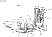
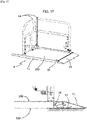
- This access ramp 15 is mounted to move between a raised position in which it projects from the active face 100 of the load support of the plate 10 and forms a stopper along one of the transverse edges 110 of the plate 10 and a lowered position in which it forms, in the horizontally positioned state of the plate 10 with the active face 100 of the load support of the plate 10 forming the top face of the plate 10, an inclined ramp with a downward slope from the face 100 active load support of said tray 10.
- the ramp 15 is equipped with at least one return member 16 in the raised position and the platform 9 is equipped with a drive control member 17 in movement of the ramp 15 from the raised position to the lowered position.
- This control member 17, which extends at least partially projecting from the so-called underside face 130 opposite the active load support face 100 of the plate 10, is configured to pass from an inactive position, in which the ramp 15 is raised, to an active position, in which the ramp 15 is lowered by simple bearing contact with the ground in the state driven in displacement of said platform 9 in the direction of a lowering of said platform 9 to a support position on the ground of said platform 9.
- This lowering of the platform 9 can be obtained by extending the mast and/or by pivoting movement of the platform in the direction of deployment.
- the control member 17 is here in the form of a pivoting lever connected by a linkage to the access ramp 15 .
- the return member 16 in the raised position of the ramp 15 is itself formed by a spring.
- the ramp 15 can be returned to the raised position under the effect of its own weight.
- the mast 5 of adjustable length and of longitudinal axis XX' is itself a telescopic mast comprising a plurality of elements 6 mounted in sliding interlocking in a direction parallel to the longitudinal axis of the mast. These elements 6 are here each formed by a frame. These frames are interconnected by actuators, such as cylinders shown at 23 in the figures or by chains shown at 8 in the figures. Again, extending or retracting the actuators makes it possible to vary the length of mast 5.
- the platform 9 is pivotally coupled to the lowermost element 6 of the mast 5 while the movable part of the base is coupled to the uppermost element of the mast in the extended position, that is to say of maximum length of the mast 5.
- the mast 5 comprises three elements mounted in sliding interlocking, namely an upper element coupled to the movable part 4 of the base 2, an intermediate element and a lower element to which the platform , in particular the support 11 of the platform 9, is pivotally connected.
- the mast therefore extends by displacement of the intermediate element and of the lower element relative to the upper element.
- the number of intermediate elements of the mast can vary between 0 and n, n being an integer.
- the mast therefore generally comprises at least two elements mounted in sliding interlocking, namely an upper element coupled to the movable part 4 of the base 2 and a lower element to which the platform, in particular the support 11 of the platform 9 , is pivotally connected, and from 0 to n intermediate elements.
- the mobile part 4 of the base 2 to which this mast 5 is coupled is for its part, for its mobile mounting in the direction of a rimpedement or a separation of the fixed part 3 of the base 2, mounted mobile according to a direction parallel to the YY' axis of the pivot connection 12 from the platform 9 to the mast 5.
- the mobile part 4 and the fixed part 3 of the base 2 are connected to each other by a connection 13 to sliding interlock.
- the fixed part 3 of the base 2 is in the form of a parallelepipedic block whose base is adapted to be fixed, for example by bolting on the part of the chassis arranged at the rear of the cockpit of the heavy vehicle.
- This parallelepipedal block is crossed by a section of hollow beam.
- the mobile part of the base 4 is formed by a U-shaped stirrup inside which one of the constituent frames of the mast 5 is inserted. This frame is formed by the frame forming the upper part of the mast in the extended position of the mast 5.
- the stirrup is also equipped with a section of beam.
- the beam section of the fixed part 3 of the base 2 and the beam section of the mobile part 4 of the base 2 fit one inside the other.
- the extension that is to say the extension of the rod of the actuator, causes a movement of the mobile part 4 of the base 2 in the direction of a spacing of the fixed part 3 of the base 2 while the retraction of the rod of the actuator causes a movement of the mobile part 4 of the base 2 in the direction of a rimpedement of the fixed part 3 of the base 2.
- the latter comprises a communication system 18 .
- This communication system 18 can communicate with a remote terminal 19 by wired or wireless link.
- the communication system 18 is a wireless communication system, such as a radio transmitter/receiver, configured to communicate with the remote terminal 19 which can form a single and same element with the remote control 28 of the system. 27 for opening/closing the door of the cockpit 25, as described above.
- This communication system 18 allows an exchange of information with the remote terminal 19 held by the user of the device 1 for access.
- the access device 1 also comprises a control unit 7 configured to acquire data from the communication system 18 and to control the actuators 20, 21, 22, 23 according to at least said data.
- Said control unit 7 is in the form of an electronic and computer system which comprises for example a microprocessor and a working memory.
- the control unit can take the form of a programmable automaton. That is, the described functions and steps can be implemented as a computer program or via hardware components (eg programmable gate arrays).
- the functions and steps performed by the control unit or its modules can be performed by instruction sets or computer modules implemented in a processor or controller or be performed by dedicated electronic components or components of the FPGA or ASIC. It is also possible to combine computer parts and electronic parts.
- the unit or means or modules of said unit are configured to carry out a given operation
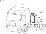
- the operation of the access device 1 is as follows. It is assumed that the fixed 3 and mobile 4 parts of the base 2 are close to each other and that the platform is in the folded position against the mast, as illustrated in figure 1 and 2 .
- the mobile part of the base is therefore movable in a direction transverse to the front/rear direction of the heavy vehicle.
- the platform In this position separated from the mobile part of the base where the mast is above the ground, the platform can be brought into the deployed position by pivoting towards the front of the heavy vehicle and the guardrails 14 in the position of use, as shown in figure 6 .
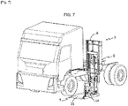
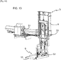
- the mast frames are then moved by sliding movement in the direction of an increase in the length of the mast towards the ground so that the lower end of the mast equipped with the platform comes to rest on the ground as illustrated in figure 7 .
- the ramp 15 for access to the platform 9 is in the lowered position and the wheelchair user can, by rolling his wheelchair, bring his wheelchair onto the platform 9 in a position in which he extends back to the mast in order to be able to exit forwards via the access ramp 15 of the platform 9.
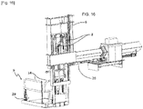
- the frames of the mast are driven in displacement in the direction of a reduction in the length of the mast to bring the platform 9 to the level of the floor of the cockpit, the opening of the cockpit having been previously ordered.
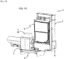
- the access ramp 15 is returned to the raised position to form a stop for the chair. This configuration is shown in figure 8 .
- the movement of the platform plate to a position in which the plate extends cantilevered relative to the support 11 is controlled to allow the user to come opposite the opening of the cabin of steering closed by the door. In this position, the user can transfer to the driver's seat of the cockpit before manually folding his wheelchair to store it in the cockpit. Once the transfer has been made, the user has the possibility of ordering an additional elevation of the platform to facilitate the dismantling of the chair. Subsequently, the plate 10 of the platform 9 is brought plumb and above the support 11 and the platform 9 is folded against the mast 5 before moving the movable part 4 of the base 2 and the associated mast in the meaning of bringing the fixed part closer to the base. The vehicle driven by the user can then move.
- the driving members of such a vehicle can be manually operated members suitable for a person in a wheelchair in a manner known per se.
- the access device 1 is arranged on the heavy vehicle so that, in the position separated from the mobile part of the base from the fixed part of the base, the movement of the platform plate from the position in which it extends plumb and above the support to a position in which it extends cantilevered relative to the support is effected by moving the platform in the direction of the front of the vehicle.
- the procedure is similar.
- the user controls, using his remote terminal, the deployment of the access device 1 for bringing the plate from the platform opposite the opening of the cockpit.
- the user can then transfer himself manually onto the plate of the platform after having positioned his wheelchair on said plate.
- the plate of the platform is then driven in sliding movement to a position in which it is arranged to plumb and above the platform support.
- the mast frames can then be moved in the direction of an elongation of the mast to bring the platform 9 in contact with the ground.
- the wheelchair user can then disembark from the platform 9.
- the frames of the mast can be driven in the direction of a reduction in the length of the mast 3, the platform 9 folded down along the mast and the mobile part of base 2 brought closer to the fixed part of base 2.
- the disembarkation process is complete.
- presence and/or position sensors can be provided at different locations of the access device 1 to allow synchronized control of the movements, as described above.
- the control unit 7 is also configured to acquire the data from these various sensors.
- the design of the access device 1, as described above, allows either the driving of such a heavy vehicle by a person in a wheelchair or by a person whose mobility is not reduced.
Landscapes
- Health & Medical Sciences (AREA)
- Public Health (AREA)
- Life Sciences & Earth Sciences (AREA)
- Animal Behavior & Ethology (AREA)
- General Health & Medical Sciences (AREA)
- Veterinary Medicine (AREA)
- Jib Cranes (AREA)
- Forklifts And Lifting Vehicles (AREA)
- Vehicle Step Arrangements And Article Storage (AREA)
Applications Claiming Priority (1)
| Application Number | Priority Date | Filing Date | Title |
|---|---|---|---|
| FR2012754A FR3117011B1 (fr) | 2020-12-07 | 2020-12-07 | Dispositif d’accès à une cabine de pilotage d’un véhicule lourd, et véhicule lourd équipé d’un tel dispositif d’accès |
Publications (1)
| Publication Number | Publication Date |
|---|---|
| EP4008300A1 true EP4008300A1 (de) | 2022-06-08 |
Family
ID=74347358
Family Applications (1)
| Application Number | Title | Priority Date | Filing Date |
|---|---|---|---|
| EP21212727.8A Withdrawn EP4008300A1 (de) | 2020-12-07 | 2021-12-07 | Zugangsvorrichtung zu einer fahrerkabine eines fahrzeugs und fahrzeug mit einer solchen zugangsvorrichtung |
Country Status (2)
| Country | Link |
|---|---|
| EP (1) | EP4008300A1 (de) |
| FR (1) | FR3117011B1 (de) |
Citations (3)
| Publication number | Priority date | Publication date | Assignee | Title |
|---|---|---|---|---|
| WO1992010422A1 (en) * | 1990-12-04 | 1992-06-25 | WALLACE, Gregory, Stewart | Elevating apparatus |
| US5431522A (en) * | 1994-06-14 | 1995-07-11 | Ross; Robert E. | Low profile scooter holder |
| WO2006135970A1 (en) * | 2005-06-21 | 2006-12-28 | Razorback Vehicles Corporation Limited | A wheelchair platform |
-
2020
- 2020-12-07 FR FR2012754A patent/FR3117011B1/fr active Active
-
2021
- 2021-12-07 EP EP21212727.8A patent/EP4008300A1/de not_active Withdrawn
Patent Citations (3)
| Publication number | Priority date | Publication date | Assignee | Title |
|---|---|---|---|---|
| WO1992010422A1 (en) * | 1990-12-04 | 1992-06-25 | WALLACE, Gregory, Stewart | Elevating apparatus |
| US5431522A (en) * | 1994-06-14 | 1995-07-11 | Ross; Robert E. | Low profile scooter holder |
| WO2006135970A1 (en) * | 2005-06-21 | 2006-12-28 | Razorback Vehicles Corporation Limited | A wheelchair platform |
Also Published As
| Publication number | Publication date |
|---|---|
| FR3117011B1 (fr) | 2023-05-19 |
| FR3117011A1 (fr) | 2022-06-10 |
Similar Documents
| Publication | Publication Date | Title |
|---|---|---|
| CA2790463C (fr) | Systeme d'acces a un habitacle | |
| CA2197034A1 (fr) | Remorque deployable en gradins | |
| EP3248836B1 (de) | Transport- und nutzfahrzeug, mobile logistikbasis, die ein solches fahrzeug umfasst, und zelle für ein solches fahrzeug | |
| EP2616279B1 (de) | Zugangsvorrichtung von bahnsteig ins fahrzeug | |
| EP1476343A1 (de) | Hebevorrichtung sowie sackkarre | |
| EP2917069B1 (de) | Anordnung zur formung einer zugangsrampe für personen mit eingeschränkter mobilität und damit ausgestattetes fahrzeug | |
| EP1995111A1 (de) | Hängegerüst für einen miIitärischen Fahrzeugsitz | |
| EP4008300A1 (de) | Zugangsvorrichtung zu einer fahrerkabine eines fahrzeugs und fahrzeug mit einer solchen zugangsvorrichtung | |
| EP4281360B1 (de) | Verfahren und anordnung der stabilisatorführung für fahrzeugtüren mit pleuelstangenschloss | |
| EP2450017B1 (de) | Verfahren zur Bettmontage | |
| WO2024047306A1 (fr) | Engin de manutention de charge | |
| FR2537121A1 (fr) | Dispositif elevateur pour personnes et objets a adapter a une voiture ferroviaire ou autre vehicule | |
| FR2999551A1 (fr) | Equipement de securite pour quai, systeme et procedes afferents | |
| WO1997032747A1 (fr) | Plate-forme repliable et unite mobile ainsi equipee | |
| EP0900692B1 (de) | Einheit aus abnehmbarer Karosseriebaugruppe und Trägerfahrzeug, Methode zum Kuppeln einer derartigen Einheit, sowie mit einer solchen Einheit ausgerüstetes Fahrzeug | |
| EP0377222B1 (de) | Ausziehleiter auf einem Fahrgestell | |
| FR3121166A1 (fr) | Dispositif d’accès en hauteur tel que plateforme avec stabilisateurs et pieds télescopiques | |
| EP3354831B1 (de) | Gehäuse für den transport und das ausschiffen eines roboters | |
| FR3043394B1 (fr) | Systeme d'embarquement d'un chariot elevateur sous une plateforme de chargement d'un vehicule de transport | |
| FR2918322A1 (fr) | Betaillere comprenant au moins un plancher mobile | |
| FR2904596A1 (fr) | Vehicule automobile a cabine amovible | |
| WO2024121502A1 (fr) | Engin pour le travail en elevation de personne | |
| EP4703318A1 (de) | Hebetisch zur reparatur und/oder wartung und/oder überwachung eines rollenden fahrzeugs | |
| FR3041949B1 (fr) | Procede et dispositif de preparation de receptacle e charge par chargement en charges dudit receptacle | |
| WO2012143623A1 (fr) | Dispositif de chargement/déchargement escamotable pour véhicule, notamment utilitaire. |
Legal Events
| Date | Code | Title | Description |
|---|---|---|---|
| PUAI | Public reference made under article 153(3) epc to a published international application that has entered the european phase |
Free format text: ORIGINAL CODE: 0009012 |
|
| STAA | Information on the status of an ep patent application or granted ep patent |
Free format text: STATUS: THE APPLICATION HAS BEEN PUBLISHED |
|
| AK | Designated contracting states |
Kind code of ref document: A1 Designated state(s): AL AT BE BG CH CY CZ DE DK EE ES FI FR GB GR HR HU IE IS IT LI LT LU LV MC MK MT NL NO PL PT RO RS SE SI SK SM TR |
|
| STAA | Information on the status of an ep patent application or granted ep patent |
Free format text: STATUS: THE APPLICATION IS DEEMED TO BE WITHDRAWN |
|
| 18D | Application deemed to be withdrawn |
Effective date: 20221209 |