EP4008480A1 - Spanneinrichtung - Google Patents
Spanneinrichtung Download PDFInfo
- Publication number
- EP4008480A1 EP4008480A1 EP21211949.9A EP21211949A EP4008480A1 EP 4008480 A1 EP4008480 A1 EP 4008480A1 EP 21211949 A EP21211949 A EP 21211949A EP 4008480 A1 EP4008480 A1 EP 4008480A1
- Authority
- EP
- European Patent Office
- Prior art keywords
- clamping
- connecting piece
- thread
- clamping element
- relative
- Prior art date
- Legal status (The legal status is an assumption and is not a legal conclusion. Google has not performed a legal analysis and makes no representation as to the accuracy of the status listed.)
- Granted
Links
Images

Classifications
-
- B—PERFORMING OPERATIONS; TRANSPORTING
- B25—HAND TOOLS; PORTABLE POWER-DRIVEN TOOLS; MANIPULATORS
- B25B—TOOLS OR BENCH DEVICES NOT OTHERWISE PROVIDED FOR, FOR FASTENING, CONNECTING, DISENGAGING, OR HOLDING
- B25B5/00—Clamps
- B25B5/06—Arrangements for positively actuating jaws
- B25B5/061—Arrangements for positively actuating jaws with fluid drive
-
- B—PERFORMING OPERATIONS; TRANSPORTING
- B25—HAND TOOLS; PORTABLE POWER-DRIVEN TOOLS; MANIPULATORS
- B25B—TOOLS OR BENCH DEVICES NOT OTHERWISE PROVIDED FOR, FOR FASTENING, CONNECTING, DISENGAGING, OR HOLDING
- B25B5/00—Clamps
- B25B5/16—Details, e.g. jaws, jaw attachments
Definitions
- the invention relates to a clamping device according to the preamble of claim 1.
- Such clamping devices are usually used in the form of vertical clamps for clamping workpieces and are, for example EP 3 593 946 A1 and DE 101 08 134 A1 known.
- the workpiece which can be a workpiece made of any material, in particular wood or wood substitutes or plastics or metals, is clamped between two clamping elements of the clamping device.
- the two clamping elements each have a clamping surface which, in the clamped state, rests on opposite sides of the workpiece. In the released state, the workpiece rests on one clamping surface due to gravity, while a gap is created between the other clamping surface and the workpiece. As a rule, this gap should be large enough to be able to insert a specific workpiece between the two clamping surfaces.
- this approach also gives rise to problems in practice. After the workpiece has been placed between the two clamping surfaces, these must then be clamped.
- this gap dimension known as the clamping stroke, which forms between one clamping surface and the workpiece in the released state, is to be dimensioned in such a way that, for example, a fingers cannot reach into this gap. There is therefore a need to be able to individually change a corresponding clamping stroke depending on the workpiece used.
- EP 3 593 946 A1 describes a vertical clamp in which the one clamping surface can be moved towards the other clamping surface by means of a piston and a piston rod guided therein for clamping onto the other clamping surface.
- the adjustment of the stroke can be read off a scale.
- WO 2016/071351 A1 is known to realize different strokes by introducing stepped spacers, which are introduced together with the workpiece between the clamping surfaces.
- the clamping stroke can only be set in discrete steps, since the spacer used has different steps.
- a piston rod has to be moved manually within a guide.
- the setting of a predefined clamping stroke is only possible with relative imprecision.
- the clamping device according to the invention which can be designed in particular as a vertical clamp, can be used to clamp workpieces, in particular those made of wood or wood substitutes, plastics or metals.
- the clamping device has a first clamping element with a first clamping surface and a second clamping element with a second clamping surface facing the first clamping surface.
- the first clamping element and the second clamping element can be moved relative to each other for clamping or releasing a workpiece between the clamping surfaces via a drive device.
- the first clamping element is fastened to a connecting piece having a first thread or is formed in one piece with the latter.
- the second clamping element is mounted on a bearing section.
- a clamping element that is movable relative to the bearing section is displaceably mounted in the bearing section.
- the tensioning element has a mating thread that matches the first thread.
- the clamping device thus enables a simple adjustment of the first clamping element relative to the second clamping element, in which both are connected to one another via the connecting piece and a thread.
- the first clamping element By turning the first clamping element, it can be displaced relative to the second clamping element, so that the position of the first clamping surface relative to the second clamping surface can be displaced. That's how he can desired clamping stroke can be continuously adjusted depending on the size of the workpiece.
- the tensioning device according to the invention comprises a cylinder in which the tensioning element is displaceably guided in the form of a piston.
- the piston can be displaced in different ways in order to clamp the clamping device and clamp the workpiece.
- the cylinder can be set up in such a way that the clamping element moves the first clamping surface towards the second clamping surface by evacuating or building up pressure in the cylinder.
- the clamping device according to the invention can be arranged, for example, on a suction traverse that evacuates the interior of the cylinder.
- the interior of the cylinder can also be filled with a fluid in order to activate the tensioning device.
- the axial direction of the thread and the mating thread preferably runs perpendicular to the clamping surfaces.
- the relative rotation between the connecting piece and the clamping element causes a change in the distance between the two clamping surfaces.
- a relative rotation between the connecting piece and the tensioning element only opens up the possibility that a relative adjustment of the clamping stroke is made possible. It is thus possible, for example, for a slight turning of the connecting piece relative to the clamping element to enable a relative axial displacement of the two clamping surfaces with respect to one another. The mutual twisting itself can therefore act to lock or cancel the distance between the two clamping surfaces.
- the connecting piece has a detachable first anti-rotation device which is designed to prevent relative rotation between the connecting piece and the tensioning element in the locked state and to enable such relative rotation in the released state.
- this anti-twist device ensures that, during normal operation of the clamping device, the clamping stroke is prevented from changing in an unintentional manner.
- the pulling element can be tightened or loosened by hand by one person.
- a preferred embodiment provides that the pulling element is coupled at the end facing away from the first clamping surface to a lock nut, the thread of which engages in the mating thread of the connecting piece.
- the lock nut ensures that the connector cannot be turned any further than is absolutely necessary.
- the lock nut and tension element are partially decoupled, so that the connecting piece can rotate relative to the tension element.
- the tension element tightens the lock nut so that relative rotation between the connecting piece and the tension element is no longer possible.
- the tension element can be designed as a tension screw which is rotatably coupled to the lock nut. This causes that when locking the The tension screw pulls the lock nut against the connecting piece, thus blocking the relative rotation between the connecting piece and the tensioning element.
- a second anti-twist device is effective according to a preferred embodiment of the invention between the named components, which prevents the relative turning of the lock nut and the connecting piece and only allows their axial displacement.
- Such an anti-twist device can, for example, be designed in such a way that the counter nut and connecting piece engage in one another via a tongue and groove connection.
- the lock nut can have a corresponding spring which engages in a groove provided in the connecting piece.
- tongue and groove are attached to the lock nut or the connecting piece.
- the clamping device 1 is preferably oriented as a vertical clamp, with the lifting movement for clamping or releasing a workpiece then taking place in the vertical direction Z.
- the workpiece is clamped between a first clamping element 2 with a first clamping surface 2a and a second clamping element 7 with an associated second clamping surface 7a.
- the two clamping surfaces 2a and 7a lie opposite one another in the stroke direction Z and can be moved relative to one another in this direction.
- a tensioning element 8 is provided for this relative movement, which is displaceable in the stroke direction Z relative to a bearing section 5 in which a plain bearing 5a for guiding the tensioning element 8 is located.
- the clamping element 8 is connected to the clamping element 2 via a connecting piece 10 .
- the bearing section 5 is fixedly arranged on a base section of the clamping device 1 .
- the entire clamping device 1 can preferably be connected to a substructure 12, not shown here.
- the substructure 12 can preferably have a suction device or compressed air device, via which the clamping device 1 can be actuated.
- the workpiece 4 is placed between the two clamping surfaces 2a and 7a.
- the workpiece itself has the height h in the stroke direction Z. This means that the two clamping surfaces 2a and 7a must be at least the distance h plus a clamping stroke d apart for inserting or removing the workpiece.
- the clamping stroke d If possible, do not reach the thickness of a human finger, so that it can be avoided that a finger can be pinched between the top of the workpiece 4 and the upper clamping surface 2a.
- the distance d+h between the two clamping surfaces 2a and 7a must therefore be adjusted.
- the connecting piece 10 is provided with an external thread 10a which is screwed into a corresponding internal thread 8a of the tensioning element 8 .
- the clamping element 8 itself is preferably designed as a piston, which is slidably mounted in a cylinder 9 in the direction of stroke Z.
- the clamping element 8 can be moved in the stroke direction Z, for example by evacuating the cubic capacity of the cylinder 9, so that the surface 2a moves towards the surface 7a and the workpiece 4 is clamped between the surfaces 2a and 7a.
- ventilation of the cubic capacity of the cylinder 9 ensures that the tension is released.
- it is also possible to move the clamping element in a different way for example to initiate the clamping process using compressed air and correspondingly release the clamping process by evacuation.
- other drives are also fundamentally conceivable.
- the clamping device according to the invention has a first Anti-twist device on. This is formed by a lock nut 6 which, like the connecting piece 10 , has an external thread 6a with which it is screwed into the internal thread 8a of the clamping element 8 .
- the lock nut 6 ensures that the connection piece 10 and the lock nut 6 can no longer be twisted relative to the clamping element 8 when it rests against the connecting piece 10 in a non-positive manner.
- This non-positive contact is produced via a clamping screw 3, which is passed through an opening 10c, which extends through the connecting piece 10 in the stroke direction Z.
- This clamping screw 3 is connected to the lock nut 6 at its free end. If the clamping screw 3 is turned in a first direction, the lock nut 6 and the connecting piece 10 are braced against one another in the axial direction (parallel to Z) and relative rotation between the connecting piece 10 and the clamping element 8 is not possible. Correspondingly, when turning the clamping screw 3 in the opposite direction, the axial tension between the lock nut 6 and the connecting piece 10 is released and play is created, which allows the connecting piece 10 and the lock nut 6 to rotate relative to the clamping element 8 .
- the lock nut 6 is also secured with a further anti-rotation device against rotation relative to the connecting piece 10 .
- the lock nut 6 has a projection 6b, which dips into a corresponding recess 10b in the connecting piece 10.
- the projection and recess could just as well be arranged on the respective other component. Since these two sections, the projection and the recess, engage in a form-fitting manner, there is a relative torsion between lock nut 6 and connecting piece 10 is no longer possible.
- the turnbuckle 3 is then passed through the opening 10c in the connector 10. This opening is aligned with a threaded hole 6c, which is designed as an internal thread of the lock nut 6.
- the clamping screw 3 engages in this threaded hole 6c.
- the clamping device 1 according to the invention can be adjusted particularly conveniently with regard to the clamping stroke to be set and fixed in any desired adjustment position.
Landscapes
- Engineering & Computer Science (AREA)
- Mechanical Engineering (AREA)
- Clamps And Clips (AREA)
- Jigs For Machine Tools (AREA)
Abstract
Description
- Die Erfindung betrifft eine Spanneinrichtung nach dem Oberbegriff des Anspruchs 1.
- Solche Spanneinrichtungen werden in der Regel in Form von Vertikalspannern zum Einspannen von Werkstücken verwendet und sind beispielsweise aus
EP 3 593 946 A1 undDE 101 08 134 A1 bekannt. - Das Werkstück, bei dem es sich um ein Werkstück aus einem beliebigen Material, insbesondere aus Holz oder Holzersatzstoffen oder Kunststoffen oder Metallen handeln kann, wird zwischen zwei Klemmelementen der Spanneinrichtung eingespannt. Die beiden Klemmelemente weisen jeweils eine Klemmfläche auf, die im gespannten Zustand an gegenüberliegenden Seiten des Werkstücks anliegen. Im gelösten Zustand liegt das Werkstück infolge der Schwerkraft auf der einen Klemmfläche auf, während zwischen der anderen Klemmfläche und dem Werkstück ein Spalt entsteht. Dieser Spalt sollte in der Regel groß genug sein, ein bestimmtes Werkstück zwischen die beiden Klemmflächen einbringen zu können. Allerdings ergeben sich aus dieser Vorgehensweise auch in der Praxis Probleme. Nachdem nämlich das Werkstück zwischen den beiden Klemmflächen platziert worden ist, müssen diese dann gespannt werden. Dabei ist aus Arbeitsschutzgründen darauf zu achten, dass der genannte Spalt zwischen der einen Klemmfläche und dem Werkstück lediglich so groß ist, dass eine Person sich beim Spannen der Spanneinrichtung nicht die Hand oder die Finger einklemmen kann. Demzufolge ist in der Regel abhängig vom Werkstück dieses als Klemmhub bezeichnete Spaltmaß, welches sich zwischen der einen Klemmfläche und dem Werkstück im gelösten Zustand ausbildet, so zu dimensionieren, dass beispielsweise ein Finger nicht in diesen Spalt hineinreichen kann. Es besteht also der Bedarf, einen entsprechenden Klemmhub abhängig von dem verwendeten Werkstück individuell verändern zu können.
- In der Vergangenheit sind insbesondere bei Vertikalspannern unterschiedliche Möglichkeiten eingerichtet worden, wie ein solcher Klemmhub veränderbar sein soll. In
EP 3 593 946 A1 wird ein Vertikalspanner beschrieben, bei dem sich die eine Klemmfläche auf die andere Klemmfläche mittels eines Kolbens und einer darin geführten Kolbenstange zum Spannen auf die andere Klemmfläche zu bewegen lässt. Zur Veränderung des maximalen Hubs wird vorgeschlagen, die Kolbenstange mittels einer Madenschraube relativ zum Kolben zu verstellen, wobei die Kolbenstange selbst dann mittels einer nicht näher definierten Verriegelungseinrichtung verriegelt werden kann. Über eine Skala lässt sich die Verstellung des Hubs ablesen. AusWO 2016/071351 A1 ist bekannt, unterschiedliche Hübe durch Einbringen von gestuften Distanzstücken zu realisieren, welche zusammen mit dem Werkstück zwischen den Klemmflächen eingebracht werden. - Im letztgenannten Verfahren lässt sich der Klemmhub nur in diskreten Schritten einstellen, da das verwendete Distanzstück unterschiedliche Stufen aufweist. In dem anderen geschilderten Fall, bei dem sich der Gesamthub des Kolbens verändern lässt, ist allerdings eine Kolbenstange innerhalb einer Führung händisch zu verschieben. Insoweit ist die Einstellung eines vordefinierten Klemmhubs nur verhältnismäßig unpräzise möglich.
- Aufgabe der vorliegenden Erfindung ist es daher, die eingangs genannte Spannvorrichtung dergestalt zu verbessern, dass mit ihr eine möglichst genaue Einstellung des Klemmhubs möglich ist.
- Gelöst wird diese Aufgabe durch eine Spanneinrichtung mit den Merkmalen des Anspruchs 1. Vorteilhafte Ausführungsformen finden sich in den Unteransprüchen.
- Die erfindungsgemäße Spanneinrichtung, die insbesondere als Vertikalspanner ausgebildet sein kann, kann zum Einspannen von Werkstücken, insbesondere solchen aus Holz oder Holzersatzstoffen, Kunststoffen oder Metallen eingesetzt werden. Die Spanneinrichtung weist dabei ein erstes Klemmelement mit einer ersten Klemmfläche und ein zweites Klemmelement mit einer der ersten Klemmfläche zugewandten zweiten Klemmfläche auf. Das erste Klemmelement und das zweite Klemmelement sind dabei relativ zueinander zum Einspannen oder Lösen eines Werkstücks zwischen den Klemmflächen über eine Antriebseinrichtung bewegbar. Dabei ist das erste Klemmelement an einem ein erstes Gewinde aufweisenden Verbindungsstück befestigt oder einstückig mit diesem ausgebildet. Das zweite Klemmelement ist an einem Lagerabschnitt gelagert. In dem Lagerabschnitt ist wiederum ein relativ zum Lagerabschnitt bewegliches Spannelement verschieblich gelagert. Das Spannelement weist dabei ein zum ersten Gewinde passendes Gegengewinde auf. Erfindungsgemäß ist nun vorgesehen, dass das Verbindungsstück und das Spannelement über das Gewinde und das Gegengewinde miteinander verbunden sind.
- Die erfindungsgemäße Spanneinrichtung ermöglicht so ein einfaches Verstellen des ersten Klemmelement relativ zum zweiten Klemmelement, in dem beide über das Verbindungsstück und ein Gewinde miteinander verbunden sind. Auf diese Weise lässt sich durch Drehen des ersten Klemmelements dieses gegenüber dem zweiten Klemmelement verschieben, sodass sich dabei die relative Lage der ersten Klemmfläche zur zweiten Klemmfläche verschieben lässt. So kann der angestrebte Klemmhub abhängig von der Größe des Werkstücks stufenlos eingestellt werden.
- Nach einer bevorzugten Ausführungsform der vorliegenden Erfindung ist vorgesehen, dass die erfindungsgemäße Spanneinrichtung einen Zylinder umfasst, in dem das Spannelement in Gestalt eines Kolbens verschieblich geführt ist. Die Verschiebung des Kolbens lässt sich auf unterschiedliche Weise bewerkstelligen, um die Spanneinrichtung zu spannen und das Werkstück einzuklemmen. Zum Beispiel kann dazu der Zylinder so eingerichtet sein, dass das Spannelement durch Evakuieren oder Druckaufbau des Zylinders die erste Klemmfläche auf die zweite Klemmfläche zubewegt. Im ersten Fall kann die erfindungsgemäße Spanneinrichtung beispielsweise auf einer Saugtraverse angeordnet sein, die den Innenraum des Zylinders evakuiert. Im zweiten Fall kann natürlich der Innenraum des Zylinders auch mit einem Fluid gefüllt werden, um die Spanneinrichtung zu aktivieren. Bevorzugt verläuft dabei die Axialrichtung des Gewindes und des Gegengewindes senkrecht zu den Klemmflächen.
- Zur Verstellung des Klemmhubs ist es besonders vorteilhaft, dass die Relativdrehung zwischen dem Verbindungsstück und dem Spannelement eine Änderung des Abstandes der beiden Klemmflächen bewirkt. Natürlich ist auch denkbar, dass eine Relativdrehung zwischen dem Verbindungsstück und dem Spannelement lediglich die Möglichkeit eröffnet, dass eine relative Verstellung des Klemmhubs ermöglicht wird. So ist es beispielsweise möglich, dass ein leichtes Drehen des Verbindungsstücks relativ zum Spannelement eine relative axiale Verschiebung der beiden Klemmflächen zueinander ermöglicht. Das gegenseitige Verdrehen selbst kann also eine Arretierung des Abstands der beiden Klemmflächen zueinander wirken bzw. aufheben.
- Nach einer bevorzugten Ausführungsform der vorliegenden Erfindung ist vorgesehen, dass das Verbindungsstück eine lösbare erste Verdrehsicherung aufweist, die dazu ausgelegt ist, im arretierten Zustand eine Relativdrehung zwischen dem Verbindungsstück und dem Spannelement zu verhindern und im gelösten Zustand eine solche Relativdrehung zu ermöglichen. Diese Verdrehsicherung stellt vor allem sicher, dass im Normalbetrieb der Spanneinrichtung verhindert wird, dass sich der Klemmhub in unbeabsichtigter Weise verändert. Bevorzugt kann vorgesehen sein, dass die erste Verdrehsicherung ein Zugelement umfasst, welches durch das Verbindungsstück geführt ist. Die Verdrehsicherung kann auf diese Weise unabhängig von dem Verbindungsstück und dem Spannelement erfolgen. Folglich ist die Arretierung auch hiervon entkoppelt. Das Zugelement kann dabei von Hand durch eine Person festgezogen oder gelockert werden. Auf diese Weise ist auch sichergestellt, dass die Verdrehsicherung bzw. die Aufhebung derselben haptisch erkennbar ist. Eine bevorzugte Ausführung sieht vor, dass das Zugelement am der ersten Klemmfläche abgewandten Ende mit einer Kontermutter gekoppelt ist, deren Gewinde in das Gegengewinde des Verbindungsstücks greift. Die Kontermutter stellt sicher, dass das Verbindungsstück nicht weiter gedreht werden kann, als unbedingt erforderlich. Im nicht arretierten Zustand sind Kontermutter und Zugelement teilweise entkoppelt, sodass ein relatives Verdrehen des Verbindungsstücks relativ zum Spannelement möglich ist. Im arretierten Zustand zieht das Zugelement die Kontermutter fest, sodass eine relative Verdrehung zwischen Verbindungsstück und Spannelement nicht mehr möglich ist.
- Auf bevorzugte Weise kann das Zugelement als Zugschraube ausgebildet sein, die mit der Kontermutter drehbar gekoppelt ist. Dadurch wird bewirkt, dass beim Arretieren die Zugschraube die Kontermutter gegen das Verbindungsstück zieht, und so die relative Verdrehung zwischen Verbindungsstück und Spannelement blockiert wird.
- Um die Verdrehsicherung zwischen der Kontermutter und dem Verbindungsstück sicherzustellen, ist erfindungsgemäß nach einer bevorzugten Ausführungsform eine zweite Verdrehsicherung zwischen den genannten Bauteilen wirksam, die das relative Verdrehen von der Kontermutter und dem Verbindungsstück verhindert und nur deren axiales Verschieben ermöglicht. Eine solche Verdrehsicherung kann beispielsweise dergestalt ausgebildet sein, dass Kontermutter und Verbindungsstück über eine Nut und Federverbindung ineinandergreifen. So kann beispielsweise die Kontermutter eine entsprechende Feder aufweisen, die in eine im Verbindungsstück vorgesehene Nut eingreift. Umgekehrt ist es natürlich möglich, dass Nut und Feder an der Kontermutter bzw. dem Verbindungsstück angebracht sind.
- Die Erfindung wird nachfolgend anhand der
Figuren 1 bis 4 näher erläutert. -
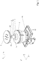
Figur 1 zeigt eine perspektivische Darstellung eines Ausführungsbeispiels einer erfindungsgemäßen Spanneinrichtung. -
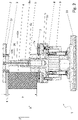
Figur 2 zeigt eine Schnittansicht durch die erfindungsgemäße Spanneinrichtung. -
Figur 3 zeigt eine Seitenansicht auf das Verbindungsstück und die Kontermutter. -
Figur 4 zeigt eine perspektivische Ansicht, die das Verbindungsstück und die Kontermutter zeigt. - Die in
Figur 1 gezeigte erfindungsgemäße Spanneinrichtung 1 ist bevorzugt als Vertikalspanner ausgerichtet, wobei die Hubbewegung zum Einklemmen bzw. Lösen eines Werkstücks dann in Vertikalrichtung Z erfolgt. Das Werkstück wird zwischen einem ersten Klemmelement 2 mit einer ersten Klemmfläche 2a und einem zweiten Klemmelement 7 mit einer zugehörigen zweiten Klemmfläche 7a gespannt. Die beiden Klemmflächen 2a bzw. 7a liegen in Hubrichtung Z einander gegenüber und lassen sich in dieser Richtung relativ zueinander bewegen. Im gezeigten Beispiel ist für diese Relativbewegung ein Spannelement 8 vorgesehen, welches gegenüber einem Lagerabschnitt 5, in dem sich ein Gleitlager 5a zur Führung des Spannelements 8 befindet, in Hubrichtung Z verschieblich ist. Das Spannelement 8 ist über ein Verbindungsstück 10 mit dem Klemmelement 2 verbunden. - Der Lagerabschnitt 5 ist auf einem Grundabschnitt der Spanneinrichtung 1 fest angeordnet. Die gesamte Spanneinrichtung 1 lässt sich bevorzugt mit einem hier nicht gezeigten Unterbau 12 verbinden. Bevorzugt kann der Unterbau 12 eine Saugeinrichtung oder Drucklufteinrichtung aufweisen, über die sich die Spanneinrichtung 1 betätigen lässt.
- Die Funktionsweise der erfindungsgemäßen Spanneinrichtung soll nun anhand der
Figuren 2 bis 4 etwas näher erläutert werden. - Wie man in dem Schnitt in
Figur 2 erkennen kann, wird das Werkstück 4 zwischen den beiden Klemmflächen 2a und 7a platziert. Das Werkstück selbst hat in Hubrichtung Z die Höhe h. Das bedeutet, dass die beiden Klemmflächen 2a und 7a zum Einführen oder Entfernen des Werkstücks mindestens um den Abstand h plus einem Klemmhub d auseinanderliegen müssen. Bei eingeschobenem Werkstück 4 darf der Klemmhub d möglichst die Dicke eines menschlichen Fingers nicht erreichen, sodass vermieden werden kann, dass zwischen der Oberseite des Werkstücks 4 und der oberen Klemmfläche 2a ein Finger eingeklemmt werden kann. Je nach Höhe h des Werkstücks 4 muss also der Abstand d + h zwischen den beiden Klemmflächen 2a und 7a angepasst werden. - Dazu ist das Verbindungsstück 10 mit einem Außengewinde 10a versehen, welches in ein entsprechendes Innengewinde 8a des Spannelements 8 eingeschraubt ist. Das Spannelement 8 selbst ist bevorzugt als Kolben ausgebildet, der in einem Zylinder 9 in Hubrichtung Z verschieblich gelagert ist. Das Spannelement 8 kann so beispielsweise durch Evakuieren des Hubraums des Zylinders 9 in Hubrichtung Z bewegt werden, sodass sich die Fläche 2a auf die Fläche 7a zubewegt und das Werkstück 4 zwischen den Flächen 2a und 7a eingespannt wird. Entsprechend sorgt eine Belüftung des Hubraums des Zylinders 9 für das Lösen der Spannung. Natürlich ist es auch möglich, das Spannelement auf andere Weise zu bewegen, beispielsweise über Druckluft den Spannvorgang einzuleiten und entsprechend durch Evakuieren den Spannvorgang aufzulösen. Natürlich sind auch andere Antriebe grundsätzlich denkbar.
- Unter bestimmten Voraussetzungen lässt sich durch den Eingriff der beiden Gewinde 10a und 8a der Abstand zwischen den beiden Klemmflächen 2a und 7a durch Verdrehen des Verbindungsstücks 10 gegenüber dem Spannelement 8 verändern. So lässt sich dann der gewünschte Klemmhub d abhängig von der Höhe h des Werkstücks 4 einstellen. Damit im laufenden Betrieb eine unbeabsichtigte Verstellung dieses Klemmhubs d nicht erfolgt, d. h. eine relative Verdrehung des Verbindungsstücks 10 und des Spannelements 8 nicht erfolgen kann, weist die erfindungsgemäße Spanneinrichtung eine erste Verdrehsicherung auf. Diese wird durch eine Kontermutter 6 gebildet, die ebenso wie das Verbindungsstück 10 ein Außengewinde 6a aufweist, mit welchem sie in das Innengewinde 8a des Spannelements 8 eingeschraubt ist. Die Kontermutter 6 sorgt bei kraftschlüssiger Anlage gegen das Verbindungsstück 10 dafür, dass sich Verbindungsstück 10 und Kontermutter 6 nicht mehr relativ zum Spannelement 8 verdrehen lassen. Diese kraftschlüssige Anlage wird über eine Spannschraube 3 hergestellt, welche durch eine Öffnung 10c, die sich in Hubrichtung Z durch das Verbindungsstück 10 erstreckt, hindurchgeführt ist. Diese Spannschraube 3 ist an ihrem freien Ende mit der Kontermutter 6 verbunden. Wird die Spannschraube 3 in eine erste Richtung gedreht, werden Kontermutter 6 und Verbindungsstück 10 in axialer Richtung (parallel zu Z) gegeneinander verspannt und eine relative Verdrehung zwischen Verbindungsstück 10 und Spannelement 8 ist nicht möglich. Entsprechend gilt beim Drehen der Spannschraube 3 in die entgegengesetzte Richtung, dass die axiale Verspannung zwischen Kontermutter 6 und Verbindungsstück 10 aufgehoben wird und ein Spiel entsteht, welches eine Verdrehung von Verbindungsstück 10 und Kontermutter 6 relativ zum Spannelement 8 ermöglicht.
- In einer bevorzugten Ausführungsform, die in den
Figuren 3 und 4 dargestellt ist, ist auch die Kontermutter 6 mit einer weiteren Verdrehsicherung gegen Verdrehen relativ zum Verbindungsstück 10 gesichert. - Dazu weist die Kontermutter 6 einen Vorsprung 6b auf, der in einen entsprechenden Rücksprung 10b im Verbindungsstück 10 eintaucht. Genauso gut könnten aber Vorsprung und Rücksprung auch am jeweils anderen Bauteil angeordnet werden. Da diese beiden Abschnitte, Vorsprung und Rücksprung, formschlüssig ineinandergreifen, ist eine relative Verdrehung zwischen Kontermutter 6 und Verbindungsstück 10 nicht mehr möglich. Die Spannschraube 3 wird dann durch die Öffnung 10c im Verbindungsstück 10 geführt. Diese Öffnung fluchtet mit einem Gewindeloch 6c, welches als Innengewinde der Kontermutter 6 ausgebildet ist. In dieses Gewindeloch 6c greift die Spannschraube 3 ein.
- Mit der dargestellten Konstruktion lässt sich die erfindungsgemäße Spanneinrichtung 1 besonders komfortabel hinsichtlich des einzustellenden Klemmhubs verstellen und in jeder gewünschten Verstelllage fixieren.
Claims (10)
- Spanneinrichtung (1), insbesondere Vertikalspanner, zum Einspannen von Werkstücken (4), insbesondere solchen aus Holz oder Holzersatzstoffen, Kunststoffen oder Metallen, aufweisend:ein erstes Klemmelement (2) mit einer ersten Klemmfläche (2a),ein zweites Klemmelement (7) mit einer der ersten Klemmfläche (2a) zugewandten zweiten Klemmfläche (7a),wobei das erste Klemmelement (2) und das zweite Klemmelement (7) relativ zueinander zum Einspannen oder Lösen eines Werkstücks (4) zwischen den Klemmflächen (2a, 7a) über eine Antriebseinrichtung bewegbar sind,wobei das erste Klemmelement (2) an einem ein erstes Gewinde (10a) aufweisenden Verbindungsstück (10) befestigt oder einstückig mit diesem ausgebildet ist und das zweite Klemmelement (7) an einem Lagerabschnitt (5) gelagert ist, in welchem ein relativ zum Lagerabschnitt (5) bewegliches Spannelement (8) verschieblich gelagert ist, das ein zum ersten Gewinde (10a) passendes Gegengewinde (8a) aufweist,wobei das Verbindungsstück (10) und das Spannelement (8) über das Gewinde (10a) und das Gegengewinde (8a) miteinander verbunden sind.
- Spanneinrichtung (1) nach Anspruch 1,
dadurch gekennzeichnet,
dass sie einen Zylinder (9) umfasst, in dem das Spannelement (8) in Gestalt eines Kolbens verschieblich geführt ist. - Spanneinrichtung (1) nach Anspruch 2,
dadurch gekennzeichnet,
dass der Zylinder so eingerichtet ist, dass das Spannelement (8) durch Evakuieren oder Druckaufbau des Zylinders (9) die erste Klemmfläche (2a) auf die zweite Klemmfläche zubewegt. - Spanneinrichtung (1) nach einem der vorigen Ansprüche,
dadurch gekennzeichnet,
dass die Axialrichtung (Z) des Gewindes (10a) und des Gegengewindes (8a) senkrecht zu den Klemmflächen (2a, 7a) verläuft. - Spanneinrichtung (1) nach einem der vorigen Ansprüche,
dadurch gekennzeichnet,
dass eine Relativdrehung zwischen dem Verbindungsstück (10) und dem Spannelement (8) eine Änderung des Abstandes (h+d) der beiden Klemmflächen (2a, 7a) bewirkt. - Spanneinrichtung (1) nach einem der vorigen Ansprüche,
dadurch gekennzeichnet,
dass das Verbindungsstück (10) eine lösbare erste Verdrehsicherung aufweist, die dazu ausgelegt ist, im arretierten Zustand eine Relativdrehung zwischen dem Verbindungsstück (10) und dem Spannelement (8) zu verhindern und im gelösten Zustand eine solche Relativdrehung zu ermöglichen. - Spanneinrichtung (1) nach Anspruch 6,
dadurch gekennzeichnet,
dass die erste Verdrehsicherung ein Zugelement (3) umfasst, welches durch das Verbindungsstück (10) geführt ist. - Spanneinrichtung (1) nach Anspruch 7,
dadurch gekennzeichnet,
dass das Zugelement (3) am der ersten Klemmfläche (2a) abgewandten Ende mit einer Kontermutter (6) gekoppelt ist, deren Gewinde in das Gegengewinde (8a) des Verbindungsstücks (10) greift. - Spanneinrichtung (1) nach Anspruch 8,
dadurch gekennzeichnet,
dass das Zugelement (3) eine Zugschraube ist, die mit der Kontermutter (6) drehbar gekoppelt ist. - Spanneinrichtung (1) nach einem der Ansprüche 8 oder 9,
dadurch gekennzeichnet,
dass zwischen der Kontermutter (6) und dem Verbindungsstück (10) eine zweite Verdrehsicherung (10b, 6b) wirksam ist, die das relative Verdrehen von der Kontermutter (6) und dem Verbindungsstück (10) verhindert und nur deren axiales Verschieben ermöglicht.
Applications Claiming Priority (1)
| Application Number | Priority Date | Filing Date | Title |
|---|---|---|---|
| DE102020132390.5A DE102020132390A1 (de) | 2020-12-07 | 2020-12-07 | Spanneinrichtung |
Publications (3)
| Publication Number | Publication Date |
|---|---|
| EP4008480A1 true EP4008480A1 (de) | 2022-06-08 |
| EP4008480C0 EP4008480C0 (de) | 2024-02-07 |
| EP4008480B1 EP4008480B1 (de) | 2024-02-07 |
Family
ID=78821531
Family Applications (1)
| Application Number | Title | Priority Date | Filing Date |
|---|---|---|---|
| EP21211949.9A Active EP4008480B1 (de) | 2020-12-07 | 2021-12-02 | Spanneinrichtung |
Country Status (3)
| Country | Link |
|---|---|
| EP (1) | EP4008480B1 (de) |
| DE (1) | DE102020132390A1 (de) |
| PL (1) | PL4008480T3 (de) |
Cited By (1)
| Publication number | Priority date | Publication date | Assignee | Title |
|---|---|---|---|---|
| CN118977120A (zh) * | 2024-10-22 | 2024-11-19 | 成都和鸿科技股份有限公司 | 一种磨粒流去除榫槽毛刺加工夹具及方法 |
Families Citing this family (1)
| Publication number | Priority date | Publication date | Assignee | Title |
|---|---|---|---|---|
| DE102023118806A1 (de) * | 2023-07-17 | 2025-01-23 | J.Schmalz Gmbh | Spannvorrichtung sowie Spannsystem umfassend eine Spannvorrichtung und eine Konsole |
Citations (5)
| Publication number | Priority date | Publication date | Assignee | Title |
|---|---|---|---|---|
| US4620695A (en) * | 1984-08-28 | 1986-11-04 | Davan Industries | Power clamping apparatus |
| DE10108134A1 (de) | 2000-02-22 | 2001-09-06 | Biesse Spa | Maschine zum Bearbeiten von Tafeln aus Holz oder dergleichen |
| DE102011012739A1 (de) * | 2011-02-24 | 2012-08-30 | Michael Weinig Ag | Spanneinrichtung für Werkstücke aus Holz, Kunststoff und dergleichen |
| WO2016071351A1 (de) | 2014-11-03 | 2016-05-12 | Homag Holzbearbeitungssysteme Gmbh | Spannvorrichtung |
| EP3593946A1 (de) | 2018-07-13 | 2020-01-15 | HOMAG GmbH | Werkstückspanner, bearbeitungsvorrichtung und spannverfahren |
-
2020
- 2020-12-07 DE DE102020132390.5A patent/DE102020132390A1/de not_active Withdrawn
-
2021
- 2021-12-02 EP EP21211949.9A patent/EP4008480B1/de active Active
- 2021-12-02 PL PL21211949.9T patent/PL4008480T3/pl unknown
Patent Citations (5)
| Publication number | Priority date | Publication date | Assignee | Title |
|---|---|---|---|---|
| US4620695A (en) * | 1984-08-28 | 1986-11-04 | Davan Industries | Power clamping apparatus |
| DE10108134A1 (de) | 2000-02-22 | 2001-09-06 | Biesse Spa | Maschine zum Bearbeiten von Tafeln aus Holz oder dergleichen |
| DE102011012739A1 (de) * | 2011-02-24 | 2012-08-30 | Michael Weinig Ag | Spanneinrichtung für Werkstücke aus Holz, Kunststoff und dergleichen |
| WO2016071351A1 (de) | 2014-11-03 | 2016-05-12 | Homag Holzbearbeitungssysteme Gmbh | Spannvorrichtung |
| EP3593946A1 (de) | 2018-07-13 | 2020-01-15 | HOMAG GmbH | Werkstückspanner, bearbeitungsvorrichtung und spannverfahren |
Cited By (1)
| Publication number | Priority date | Publication date | Assignee | Title |
|---|---|---|---|---|
| CN118977120A (zh) * | 2024-10-22 | 2024-11-19 | 成都和鸿科技股份有限公司 | 一种磨粒流去除榫槽毛刺加工夹具及方法 |
Also Published As
| Publication number | Publication date |
|---|---|
| EP4008480C0 (de) | 2024-02-07 |
| DE102020132390A1 (de) | 2022-06-09 |
| EP4008480B1 (de) | 2024-02-07 |
| PL4008480T3 (pl) | 2024-06-10 |
Similar Documents
| Publication | Publication Date | Title |
|---|---|---|
| DE4439644C2 (de) | Verriegelungssystem für Beschläge von Fahrzeugsitzen mit freischwenkbarer Rückenlehne | |
| EP0369197A1 (de) | Klammer zum Verbinden von Schaltafeln | |
| DE112013007025B4 (de) | Verriegelungsvorrichtung für teleskopierbare Möbelsäule, Möbel und Verfahren | |
| DE3144022A1 (de) | Spannfutter fuer die vorschubeinrichtung einer rohrreinigungsmaschine | |
| DE102008024314A1 (de) | Förderband | |
| EP4008480B1 (de) | Spanneinrichtung | |
| EP1995024A1 (de) | Handgeführtes Arbeitsgerät | |
| EP1809441B1 (de) | Spann- oder greifvorrichtung insbesondere linear- oder zentrischgreifer | |
| DE102012211438A1 (de) | Befestigungseinrichtung zum Befestigen von Zubehörteilen an medizinischen Einrichtungen | |
| EP3175961B1 (de) | Andruckvorrichtung für eine werkzeugmaschine zur bearbeitung von werkstücken aus holz, kunststoff und dergleichen sowie eine werkzeugmaschine mit wenigstens einer andruckvorrichtung | |
| EP0336017B1 (de) | Matrizen-Schnellspanner für Dentalzwecke | |
| DE3309513A1 (de) | Schraubstock | |
| DE102013103913A1 (de) | Spanner | |
| DE8706196U1 (de) | Winkelschraubstock | |
| EP4100207A1 (de) | Schraubzwinge | |
| DE2656543C2 (de) | Verstellbares Scharnier | |
| DE8812523U1 (de) | Schraubstock mit Leerlaufverschiebung | |
| DE1197283B (de) | Schnellverschluss | |
| EP0611623B1 (de) | Aufspannvorrichtung | |
| DE202012103126U1 (de) | Spannwerkzeug | |
| EP2578891A1 (de) | Adapter | |
| DE10052610A1 (de) | Vorrichtung zur Einstellung der Schnitttiefe eines handgeführten Elektrowerkzeugs, Schutzhaube für ein handgeführtes Elektrowerkzeug sowie handgeführtes Elektrowerkzeug | |
| DE20211968U1 (de) | Vorrichtung zur Höheneinstellung von Möbeln oder Möbelteilen, insbesondere Tischplatten | |
| DE1917085A1 (de) | Schlitzfoerderer | |
| DE10139714A1 (de) | Gelenkanordnung |
Legal Events
| Date | Code | Title | Description |
|---|---|---|---|
| PUAI | Public reference made under article 153(3) epc to a published international application that has entered the european phase |
Free format text: ORIGINAL CODE: 0009012 |
|
| STAA | Information on the status of an ep patent application or granted ep patent |
Free format text: STATUS: THE APPLICATION HAS BEEN PUBLISHED |
|
| AK | Designated contracting states |
Kind code of ref document: A1 Designated state(s): AL AT BE BG CH CY CZ DE DK EE ES FI FR GB GR HR HU IE IS IT LI LT LU LV MC MK MT NL NO PL PT RO RS SE SI SK SM TR |
|
| STAA | Information on the status of an ep patent application or granted ep patent |
Free format text: STATUS: REQUEST FOR EXAMINATION WAS MADE |
|
| 17P | Request for examination filed |
Effective date: 20221206 |
|
| RBV | Designated contracting states (corrected) |
Designated state(s): AL AT BE BG CH CY CZ DE DK EE ES FI FR GB GR HR HU IE IS IT LI LT LU LV MC MK MT NL NO PL PT RO RS SE SI SK SM TR |
|
| GRAP | Despatch of communication of intention to grant a patent |
Free format text: ORIGINAL CODE: EPIDOSNIGR1 |
|
| STAA | Information on the status of an ep patent application or granted ep patent |
Free format text: STATUS: GRANT OF PATENT IS INTENDED |
|
| INTG | Intention to grant announced |
Effective date: 20230828 |
|
| GRAS | Grant fee paid |
Free format text: ORIGINAL CODE: EPIDOSNIGR3 |
|
| GRAA | (expected) grant |
Free format text: ORIGINAL CODE: 0009210 |
|
| STAA | Information on the status of an ep patent application or granted ep patent |
Free format text: STATUS: THE PATENT HAS BEEN GRANTED |
|
| AK | Designated contracting states |
Kind code of ref document: B1 Designated state(s): AL AT BE BG CH CY CZ DE DK EE ES FI FR GB GR HR HU IE IS IT LI LT LU LV MC MK MT NL NO PL PT RO RS SE SI SK SM TR |
|
| REG | Reference to a national code |
Ref country code: GB Ref legal event code: FG4D Free format text: NOT ENGLISH |
|
| REG | Reference to a national code |
Ref country code: CH Ref legal event code: EP |
|
| REG | Reference to a national code |
Ref country code: IE Ref legal event code: FG4D Free format text: LANGUAGE OF EP DOCUMENT: GERMAN |
|
| REG | Reference to a national code |
Ref country code: DE Ref legal event code: R096 Ref document number: 502021002636 Country of ref document: DE |
|
| U01 | Request for unitary effect filed |
Effective date: 20240212 |
|
| U07 | Unitary effect registered |
Designated state(s): AT BE BG DE DK EE FI FR IT LT LU LV MT NL PT SE SI Effective date: 20240221 |
|
| PG25 | Lapsed in a contracting state [announced via postgrant information from national office to epo] |
Ref country code: IS Free format text: LAPSE BECAUSE OF FAILURE TO SUBMIT A TRANSLATION OF THE DESCRIPTION OR TO PAY THE FEE WITHIN THE PRESCRIBED TIME-LIMIT Effective date: 20240607 |
|
| PG25 | Lapsed in a contracting state [announced via postgrant information from national office to epo] |
Ref country code: GR Free format text: LAPSE BECAUSE OF FAILURE TO SUBMIT A TRANSLATION OF THE DESCRIPTION OR TO PAY THE FEE WITHIN THE PRESCRIBED TIME-LIMIT Effective date: 20240508 |
|
| PG25 | Lapsed in a contracting state [announced via postgrant information from national office to epo] |
Ref country code: HR Free format text: LAPSE BECAUSE OF FAILURE TO SUBMIT A TRANSLATION OF THE DESCRIPTION OR TO PAY THE FEE WITHIN THE PRESCRIBED TIME-LIMIT Effective date: 20240207 Ref country code: RS Free format text: LAPSE BECAUSE OF FAILURE TO SUBMIT A TRANSLATION OF THE DESCRIPTION OR TO PAY THE FEE WITHIN THE PRESCRIBED TIME-LIMIT Effective date: 20240507 |
|
| PG25 | Lapsed in a contracting state [announced via postgrant information from national office to epo] |
Ref country code: ES Free format text: LAPSE BECAUSE OF FAILURE TO SUBMIT A TRANSLATION OF THE DESCRIPTION OR TO PAY THE FEE WITHIN THE PRESCRIBED TIME-LIMIT Effective date: 20240207 |
|
| PG25 | Lapsed in a contracting state [announced via postgrant information from national office to epo] |
Ref country code: RS Free format text: LAPSE BECAUSE OF FAILURE TO SUBMIT A TRANSLATION OF THE DESCRIPTION OR TO PAY THE FEE WITHIN THE PRESCRIBED TIME-LIMIT Effective date: 20240507 Ref country code: NO Free format text: LAPSE BECAUSE OF FAILURE TO SUBMIT A TRANSLATION OF THE DESCRIPTION OR TO PAY THE FEE WITHIN THE PRESCRIBED TIME-LIMIT Effective date: 20240507 Ref country code: IS Free format text: LAPSE BECAUSE OF FAILURE TO SUBMIT A TRANSLATION OF THE DESCRIPTION OR TO PAY THE FEE WITHIN THE PRESCRIBED TIME-LIMIT Effective date: 20240607 Ref country code: HR Free format text: LAPSE BECAUSE OF FAILURE TO SUBMIT A TRANSLATION OF THE DESCRIPTION OR TO PAY THE FEE WITHIN THE PRESCRIBED TIME-LIMIT Effective date: 20240207 Ref country code: GR Free format text: LAPSE BECAUSE OF FAILURE TO SUBMIT A TRANSLATION OF THE DESCRIPTION OR TO PAY THE FEE WITHIN THE PRESCRIBED TIME-LIMIT Effective date: 20240508 Ref country code: ES Free format text: LAPSE BECAUSE OF FAILURE TO SUBMIT A TRANSLATION OF THE DESCRIPTION OR TO PAY THE FEE WITHIN THE PRESCRIBED TIME-LIMIT Effective date: 20240207 |
|
| PG25 | Lapsed in a contracting state [announced via postgrant information from national office to epo] |
Ref country code: SM Free format text: LAPSE BECAUSE OF FAILURE TO SUBMIT A TRANSLATION OF THE DESCRIPTION OR TO PAY THE FEE WITHIN THE PRESCRIBED TIME-LIMIT Effective date: 20240207 |
|
| PG25 | Lapsed in a contracting state [announced via postgrant information from national office to epo] |
Ref country code: CZ Free format text: LAPSE BECAUSE OF FAILURE TO SUBMIT A TRANSLATION OF THE DESCRIPTION OR TO PAY THE FEE WITHIN THE PRESCRIBED TIME-LIMIT Effective date: 20240207 |
|
| PG25 | Lapsed in a contracting state [announced via postgrant information from national office to epo] |
Ref country code: SK Free format text: LAPSE BECAUSE OF FAILURE TO SUBMIT A TRANSLATION OF THE DESCRIPTION OR TO PAY THE FEE WITHIN THE PRESCRIBED TIME-LIMIT Effective date: 20240207 |
|
| PG25 | Lapsed in a contracting state [announced via postgrant information from national office to epo] |
Ref country code: SM Free format text: LAPSE BECAUSE OF FAILURE TO SUBMIT A TRANSLATION OF THE DESCRIPTION OR TO PAY THE FEE WITHIN THE PRESCRIBED TIME-LIMIT Effective date: 20240207 Ref country code: SK Free format text: LAPSE BECAUSE OF FAILURE TO SUBMIT A TRANSLATION OF THE DESCRIPTION OR TO PAY THE FEE WITHIN THE PRESCRIBED TIME-LIMIT Effective date: 20240207 Ref country code: RO Free format text: LAPSE BECAUSE OF FAILURE TO SUBMIT A TRANSLATION OF THE DESCRIPTION OR TO PAY THE FEE WITHIN THE PRESCRIBED TIME-LIMIT Effective date: 20240207 Ref country code: CZ Free format text: LAPSE BECAUSE OF FAILURE TO SUBMIT A TRANSLATION OF THE DESCRIPTION OR TO PAY THE FEE WITHIN THE PRESCRIBED TIME-LIMIT Effective date: 20240207 |
|
| REG | Reference to a national code |
Ref country code: DE Ref legal event code: R097 Ref document number: 502021002636 Country of ref document: DE |
|
| PLBE | No opposition filed within time limit |
Free format text: ORIGINAL CODE: 0009261 |
|
| STAA | Information on the status of an ep patent application or granted ep patent |
Free format text: STATUS: NO OPPOSITION FILED WITHIN TIME LIMIT |
|
| 26N | No opposition filed |
Effective date: 20241108 |
|
| U20 | Renewal fee for the european patent with unitary effect paid |
Year of fee payment: 4 Effective date: 20241223 |
|
| PG25 | Lapsed in a contracting state [announced via postgrant information from national office to epo] |
Ref country code: MC Free format text: LAPSE BECAUSE OF FAILURE TO SUBMIT A TRANSLATION OF THE DESCRIPTION OR TO PAY THE FEE WITHIN THE PRESCRIBED TIME-LIMIT Effective date: 20240207 |
|
| REG | Reference to a national code |
Ref country code: CH Ref legal event code: PL |
|
| PG25 | Lapsed in a contracting state [announced via postgrant information from national office to epo] |
Ref country code: CH Free format text: LAPSE BECAUSE OF NON-PAYMENT OF DUE FEES Effective date: 20241231 |
|
| PG25 | Lapsed in a contracting state [announced via postgrant information from national office to epo] |
Ref country code: IE Free format text: LAPSE BECAUSE OF NON-PAYMENT OF DUE FEES Effective date: 20241202 |
|
| U20 | Renewal fee for the european patent with unitary effect paid |
Year of fee payment: 5 Effective date: 20251216 |
|
| PGFP | Annual fee paid to national office [announced via postgrant information from national office to epo] |
Ref country code: PL Payment date: 20251126 Year of fee payment: 5 |
|
| PG25 | Lapsed in a contracting state [announced via postgrant information from national office to epo] |
Ref country code: CY Free format text: LAPSE BECAUSE OF FAILURE TO SUBMIT A TRANSLATION OF THE DESCRIPTION OR TO PAY THE FEE WITHIN THE PRESCRIBED TIME-LIMIT; INVALID AB INITIO Effective date: 20211202 |