EP4008484B1 - Dispositif de retrait d'agrafes - Google Patents
Dispositif de retrait d'agrafes Download PDFInfo
- Publication number
- EP4008484B1 EP4008484B1 EP20847620.0A EP20847620A EP4008484B1 EP 4008484 B1 EP4008484 B1 EP 4008484B1 EP 20847620 A EP20847620 A EP 20847620A EP 4008484 B1 EP4008484 B1 EP 4008484B1
- Authority
- EP
- European Patent Office
- Prior art keywords
- staple
- motor
- sheet bundle
- placing table
- removing device
- Prior art date
- Legal status (The legal status is an assumption and is not a legal conclusion. Google has not performed a legal analysis and makes no representation as to the accuracy of the status listed.)
- Active
Links
Images


Classifications
-
- B—PERFORMING OPERATIONS; TRANSPORTING
- B25—HAND TOOLS; PORTABLE POWER-DRIVEN TOOLS; MANIPULATORS
- B25C—HAND-HELD NAILING OR STAPLING TOOLS; MANUALLY OPERATED PORTABLE STAPLING TOOLS
- B25C11/00—Nail, spike, and staple extractors
Definitions
- the present invention relates to a staple removing device according to the preamble of claim 1.
- a technology relating to a staple removing device configured to remove a staple from a sheet bundle (PTLs 1 and 2).
- This type of the staple removing device is configured to remove the staple from the sheet bundle by inserting a wedge-shaped plate between the sheet bundle and a crown portion of the staple.
- PTL 1 discloses a sheet processing device configured to remove a staple from a sheet bundle by inserting a pullout pin between the sheet bundle and the staple, and then raising the pullout pin.
- PTL 2 discloses a binding member removing device configured to insert a cutting means between a document bundle and a staple needle, to cut both leg portions of the staple needle and then to remove the staple needle from the document bundle.
- a pullout motor for operating the pullout pin and a drive motor for raising the pullout pin are respectively arranged above the pullout pin. For this reason, there is a problem that a dimension in a height direction of the device becomes large.
- an electric motor for driving the cutting means is arranged on a side of the cutting means. For this reason, there is a problem that a dimension in a width direction of the device becomes large.
- a staple removing device is to suppress dimensions in a height direction and a width direction of the device and to miniaturize the entire device.
- the present invention is defined in the independent claim 1.
- the accommodation part is arranged below the removing part when the removing part is at the second position, so that an empty space occurs below the removing part when the removing part is at the first position.
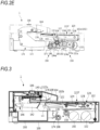
- FIG. 1A is a front perspective view of a staple removing device 1
- FIG. 1B is a rear perspective view of the staple removing device 1.
- FIG. 2A is a right front left rear perspective view of an inside of the staple removing device 1
- FIG. 2B is a left front right rear perspective view of the inside of the staple removing device 1.
- the staple removing device 1 is a device for automatically removing a staple from a sheet bundle bound by the staple, and includes a housing 100 having a substantially cuboid shape, a placing table 102 on which the sheet bundle is placed, a removing part 120 located below the placing table 102 (inside the housing 100 with respect to the placing table 102) and configured to remove the staple from the sheet bundle placed on the placing table 102, a first motor 152 configured to drive the removing part 120, and an accommodation part 200 configured to accommodate the staple removed by the removing part 120.
- a cover part 104 configured to cover a part of the placing table 102 is provided above the placing table 102 (a side on which the sheet bundle is placed with respect to the placing table 102).
- a predetermined gap is formed between the cover part 104 and the placing table 102, and the sheet bundle is inserted into the gap.
- a start switch 106 for operating the staple removal device 1 is provided on an upper surface of the cover part 104.Note that, in the present embodiment, a side on which the accommodation part 200 is provided is referred to as a rear side of the staple removing device 1, and an opposite side is referred to as a front side of the staple removing device 1.
- the housing 100 is a substantially cuboid box body whose upper side is open, and is provided therein with the removing part 120, the first motor 152, the accommodation part 200, and the like.
- the placing table 102 is provided to cover the upper opening of the housing 100, and has a placing surface 102a for placing a sheet bundle.
- the placing surface 102a is formed with an opening portion 102b so that a portion of the removing part 120 can protrude.
- the removing part 120 has a predetermined length from a tip end portion 122s to a base end portion 122k.
- the removing part 120 has a wedge plate main body 122a, which is a first part including a tip end portion 122s that can be inserted between a sheet bundle and (a crown portion Sa of) a staple and configured to remove the staple from the sheet bundle, a wedge plate base portion 122f, which is a second part configured to drive by a drive force of the first motor 152 received by racks 130 and 131, and a narrowed portion 122c, which is a third part located between the first part and the second part.
- the wedge plate main body 122a is constituted by an elongated plate-shaped member, and at least the tip end portion 122s thereof is formed in a wedge shape so as to be easily inserted between the sheet bundle and the staple and to easily pull out the staple from the sheet bundle.
- the wedge plate main body 122a has a tapered shape from the base end portion 122k toward the tip end portion 122s.
- the wedge plate main body is configured so that a plate thickness gradually decreases from the base end portion 122k toward the tip end portion 122s, in side view, and is also configured so that a plate width gradually decreases toward the tip end portion 122s, in plan view.
- the wedge plate base portion 122f has roles of supporting the wedge plate main body 122a via the narrowed portion 122c, and receiving power from the first motor 152 by the racks 130 and 131 and transmitting the power to the wedge plate main body 122a.
- the wedge plate base portion 122f has a plate holder 124 constituted by a flat plate having a substantially U-shaped section, and a pair of racks 130 and 131 attached to side surfaces of the plate holder 124.
- the wedge plate main body 122a and an attaching portion 122b extending from the wedge plate base portion 122f are attached to an upper surface of the plate holder 124.
- Each of the racks 130 and 131 is a plate-shaped member having substantially the same length as a longitudinal direction of the plate holder 124, is formed on its lower surface with a plurality of teeth (rack) in mesh with a pinion 158, which will be described later, and is configured to receive a drive force of the first motor 152.
- a sheet bundle insertion opening 108 for setting a sheet bundle in the cover part 104 is provided between the placing table 102 and the cover part 104.
- the start switch 106 is provided on the upper surface of the cover part 104 so as for a user to easily operate, and is constituted by a button for operating the staple removing device 1.
- the accommodation part 200 is a box body whose upper side is open, and is configured to be insertable/removable with respect to an opening portion 100a formed on a rear end surface of the housing 100.
- the accommodation part 200 is arranged in a space part behind and below a central part in the housing 100.
- the staple S has a crown portion Sa and a pair of leg portions Sb and Sb formed by bending both end portions in a longitudinal direction of the crown portion Sa.
- a sheet bundle P is bound by causing the pair of leg portions Sb and Sb of the staple S to penetrate a plurality of stacked sheets from the lowermost sheet toward the uppermost sheet and bending inwardly the penetrating leg portions Sb and Sb.
- a binding position of the staple S is, for example, a corner portion or an edge portion of the sheet. In the present embodiment, the staple S is removed from such sheet bundle P.
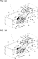
- FIG. 2A is a right front perspective view of an inside of the staple removing device 1 when the removing part 120 is at a standby position
- FIG. 2B is a left front perspective view of the inside of the staple removing device 1 when the removing part 120 is at the standby position
- FIG. 2C is a plan view of the inside of the staple removing device 1 when the removing part 120 is at the standby position
- FIG. 2D is a plan view of a first drive unit 150 and the like in the staple removing device 1
- FIG. 2E is a side view of the inside of the staple removing device 1 when the removing part 120 is at the standby position.
- FIG. 2A is a right front perspective view of an inside of the staple removing device 1 when the removing part 120 is at a standby position
- FIG. 2B is a left front perspective view of the inside of the staple removing device 1 when the removing part 120 is at the standby position
- FIG. 2C is a plan view of the inside of the staple removing
- FIG. 3 is a side cross-sectional view of the inside of the staple removing device 1 when the removing part 120 is at the standby position.
- FIG. 4 is an exploded perspective view of a staple pullout mechanism 110.
- FIG. 5A is a plan view of the removing part 120
- FIG. 5B is a side view of the removing part 120
- FIG. 5C is a cross-sectional view taken along an A-A line of the removing part 120.
- FIG. 6 is an exploded perspective view of a sheet pressing mechanism 160.
- the staple removing device 1 includes a staple pullout mechanism 110 configured to remove the staple S from the sheet bundle P, a sheet pressing mechanism 160 configured to press against the sheet bundle P placed on the placing table 102, and the above-described accommodation part 200.
- the staple pullout mechanism 110 includes the removing part 120 arranged inside the housing 100 below the placing surface 102a of the placing table 102 and configured to remove the staple S from the sheet bundle P by being inserted between the sheet bundle P and the staple, a pressing portion 140, and a first drive unit 150 configured to drive the removing part 120.
- the removing part 120 has the wedge plate 122 configured to be inserted between the crown portion Sa of the staple S and the sheet bundle P, and the racks 130 and 131 configured to move the wedge plate 122 between the crown portion Sa and the sheet bundle P.
- the removing part includes the plate holder 124 to which the wedge plate 122 is attached, a crown holder 126 configured to support the crown portion Sa of the staple S, and a holder 128 configured to restrict a position of the wedge plate 122.
- the wedge plate 122 is constituted by an elongated plate-shaped member, and includes the wedge plate main body 122a, the attaching portion 122b, and the narrowed portion 122c.
- the tip end portion 122s is configured to be movable along a plane of the placing table 102 between a standby position L1 and a removal position L2, and when the tip end portion 122s moves to the removal position L2, the tip end portion 122s is inserted between the sheet bundle P and the staple.
- the standby position L1 of the removing part 120 means a position where the removing part 120 is stopped before a removing operation is started.
- the removal position L2 of the removing part 120 means a position where the removing part 120 starts a removing operation, the removing part 120 is inserted between the crown portion Sa of the staple S and the sheet bundle P, and the staple S is removed from the sheet bundle P.
- the attaching portion 122b is integrally formed on the base end portion 122k-side of the wedge plate main body 122a, and is attached to an upper surface of the plate holder 124.
- the narrowed portion 122c is a substantially central portion in a longitudinal direction of the wedge plate 122, and is formed between the wedge plate main body 122a and the attaching portion 122b.
- a dimension D1 in the width direction of at least a part of the narrowed portion 122c is narrower than a dimension D2 in the width direction of the base end portion 122k of the wedge plate main body 122a, and is also configured to be narrower than a dimension D3 in the width direction (refer to FIG.
- the 'width direction' is, in the present embodiment, a right and left direction, and may also be a direction perpendicular to a thickness direction (height direction) and a longitudinal direction (moving direction of the removing part 120) of the wedge plate 122.
- the plate holder 124 is constituted by a flat plate having a substantially U-shaped section, has an upper surface to which the attaching portion 122b is attached, and is arranged overlapped over the crown holder 126.
- the crown holder 126 is arranged below the wedge plate 122 with the plate holder 124 being interposed therebetween, and is configured to support the crown portion Sa of the staple S removed from the sheet bundle P.
- the crown holder 126 has a groove portion 126a for preventing contact with the pressing portion 140 when the wedge plate 122 moves rearward from the front, and an opening portion 126b for dropping the staple S removed from the sheet bundle P into the accommodation part 200.
- the opening portion 126b of the crown holder 126 and the narrowed portion 122c of the wedge plate 122 attached to the plate holder 124 are arranged to be at the same position, in plan view.
- the groove portion 126a is cut out from a tip end portion to a substantially central portion of the crown holder 126, and has a width slightly wider than a width of the pressing portion 140.
- the opening portion 126b is formed at a substantially central portion in the longitudinal direction of the crown holder 126 and continuously on a base end-side of the groove portion 126a, and has a width wider than at least a length of the crown portion Sa of the staple S.
- a spring 125 is arranged between a lower surface on the other end-side of the plate holder 124 and an upper surface on the other end-side of the crown holder 126, and one end-side of the wedge plate 122 and one end-side of the crown holder 126 are urged in a direction of coming close to each other by an elastic force of the spring 125.
- one end-side indicates the rear of the staple removing device 1
- the other end-side indicates the front of the staple removing device 1.
- the holder 128 is constituted by a flat plate having a substantially U-shaped section, and is arranged overlapped on the upper surface of the plate holder 124.
- the holder 128 includes an opening portion 128a for exposing the wedge plate 122, and a support portion 128b configured to regulate the pressing portion 140 to be located below the placing table 102 at least when the removing part 120 is stopped at the standby position L1.
- a plate-shaped rack 130 having substantially the same length as the longitudinal direction of the plate holder 124 is arranged.
- the rack 130 is configured to receive a drive force of the first motor 152.
- a lower surface of the rack 130 is formed with a plurality of teeth in mesh with a pinion 158, which will be described later.
- a plate-shaped rack 131 having substantially the same length as the longitudinal direction of the plate holder 124 is arranged.
- the rack 131 is configured to receive a drive force of the first motor 152.
- a lower surface of the rack 131 is formed with a plurality of teeth in mesh with a pinion 159, which will be described later.
- a sensor 134 configured to detect a position of the removing part 120 is provided and a flag attaching plate 132 for detecting a position of the removing part 120 in a front and rear direction is provided.
- a rear end portion of the flag attaching plate 132 is provided with a first flag 132a for detecting movement of the wedge plate 122 from the standby position L1 to the removal position L2.
- a front end portion of the flag attaching plate 132 is provided with a second flag 132b for detecting arrival of the wedge plate 122 at the removal position L2.
- the sensor 134 is constituted by a transmission-type sensor and is configured to detect the first flag 132a and the second flag 132b of the rack 130 moving in the front and rear direction.
- a detection signal detected by the sensor 134 is supplied to a control unit (not shown), and the control unit is configured to control operations of the first motor 152 and a second motor 192, based on the detection signal supplied from the sensor 134.
- a first drive shaft 136 is inserted into opening portions formed in each of the flag attaching plate 132, the rack 130, the plate holder 124, the crown holder 126 and the rack 131 from the left side toward the left right side of the housing 100.
- a second drive shaft 138 is inserted into opening portions formed in each of the flag attaching plate 132, the rack 130, the plate holder 124 and the rack 131 from the left side toward the right side of the housing 100.
- the wedge plate 122, the plate holder 124, the crown holder 126, the holder 128, the racks 130, 131, and the flag attaching plate 132 are attached by the first drive shaft 136 and the second drive shaft 138, so that they constitute the removing part 120 and can integrally move forward and rearward as the removing part 120.
- the pressing portion 140 configured to restrict movement of the sheet bundle P and the staple S in an insertion direction is arranged behind the crown portion Sa located at the removal position L2 and is configured to be able to come into contact with the crown portion Sa pushed by the wedge plate 122.
- a width of the pressing portion 140 is selected to be, for example, a length in which it can support the crown portion Sa moving rearward from the front by a pushing force of the wedge plate 122 and can be inserted into the groove portion 126a of the crown holder 126.
- the pressing holder 142 configured to support the pressing portion 140 is constituted by a flat plate processed into a substantial U-shape in plan view, and a rear end-side of the pressing holder 142 is rotatably supported by a shaft 146.
- One end portion of a tension spring 144 is attached to the further rear of the pressing holder 142 than the shaft 146.
- the other end portion of the tension spring 144 is attached to a left frame 112.
- An upper end portion on the rear side of the pressing holder 142 is provided with a convex portion 142a capable of coming into contact with the support portion 128b of the holder 128.
- the first drive unit 150 includes the first motor 152, a gear 153a and the like connected to an output shaft 152a of the first motor 152, and a pair of pinions 158 and 159 respectively provided at both ends of a shaft 156, which are a first pinion part arranged at a predetermined interval in the width direction of the housing 100 and configured to mesh with the racks 130 and 131.
- a plurality of gears 153a, 153b, 154a, 154b and 155 constitutes a speed reduction mechanism.
- the width direction of the housing 100 is, in the present embodiment, the right and left direction, and may also be a direction perpendicular to both the moving direction (front and rear direction) and the height direction of the removing part 120.
- the first motor 152 has the output shaft 152a and a motor main body 152b, and is constituted by, for example, a DC motor, a DC brushless motor or the like.
- the first motor 152 is configured to drive based on an instruction from the control unit (not shown), thereby transmitting a drive force of the first motor 152 to the removing part 120 via the speed reduction mechanism and moving the removing part 120 forward or rearward. As shown in FIGS.
- the first motor 152 is arranged below the removing part 120, in the present embodiment, a second part when the tip end portion 122s of the wedge plate main body 122a (first part) of the removing part 120 is at the standby position L1.
- the lower of the removing part 120 means that at least a part of the first motor 152 including the output shaft 152a is located directly under the removing part 120.
- the first motor 152 is arranged so that the output shaft 152a is parallel to the placing surface 102a of the placing table 102.
- the output shaft is arranged to be orthogonal to the moving direction (longitudinal direction of the housing 100) of the wedge plate 122 from the front to the rear.
- the description 'the output shaft 152a is parallel to the placing surface 102a of the placing table 102' means not only a case of being perfectly parallel but also a range slightly deviating from the perfect parallelism.
- the range may be, for example, within ⁇ 5°, but may also be within ⁇ 10° depending on the required accuracy.
- 'parallel' which will be described later, includes a case of being perfectly parallel and a slightly deviating range.
- the gears 153a and 153b are two-stage drive gears, and a diameter of the gear 153a is larger than a diameter of the gear 153b.
- the gear 153a is connected to the output shaft 152a of the first motor 152.
- the gear 153b is in mesh with the gear 154a.
- the gears 154a and 154b are two-stage drive gears, and a diameter of the gear 154a is larger than a diameter of the gear 154b.
- the gear 154a is in mesh with the gear 153b, and the gear 154b is in mesh with the gear 155.
- a right end portion of the shaft 156 extending in the width direction of the housing 100 is attached to a center of the gear 155.
- the pinion 159 in mesh with the rack 131 is attached to a left and right end-side of the shaft 156 on the gear 155-side, and the pinion 158 in mesh with the rack 130 is attached to the left end-side on an opposite side.
- the sheet pressing mechanism 160 configured to press against the sheet bundle P placed on the placing table 102 includes a sheet pressing part 170 having at least a part located above the placing table 102 and configured to be movable, and a second motor 192 configured to drive the sheet pressing part 170.
- the sheet pressing part 170 has a hold lever 172 to which components constituting the sheet pressing part are attached, a pair of sheet pressing racks 174 and 175 extending in a traveling direction at a predetermined interval in the width direction of the housing 100, and a sheet pressing plate 176 configured to press the sheet bundle P placed on the placing table 102.
- the hold lever 172 has a pair of flat plates 172a and 172b arranged on the rear and front sides of the housing 100 and arranged at a predetermined interval in the width direction. Lower sides of the flat plates 172a and 172b are arranged in the housing 100, and upper sides thereof are arranged to be exposed from the placing table 102 and are covered with the cover part 104.
- a boss 178 protruding outward is attached to an outer surface of the flat plate 172a.
- One end portion of a return spring 180 constituted by a tension spring is attached to the boss 178, and the other end portion of the return spring 180 is attached to the left frame 112.
- a boss (not shown) is attached to an outer surface of the flat plate 172b, and one end portion of a return spring 181 is attached to the boss, and the other end portion of the return spring 181 is attached to a right frame 114.
- the sheet pressing rack 174 is provided at a lower front rear end portion of the flat plate 172a of the hold lever 172.
- the sheet pressing rack 174 has a substantial fan shape and is in mesh with a sheet pressing pinion 198.
- the sheet pressing rack 175 is provided at a lower front rear end portion of the flat plate 172b of the hold lever 172.
- the sheet pressing rack 175 has a substantial fan shape and is in mesh with a sheet pressing pinion 199 of a second drive unit 190.
- the sheet pressing racks 174 and 175 are configured to convert rotational motions of the sheet pressing pinions 198 and 199 into substantially linear motions.
- the sheet pressing plate 176 is configured to move toward the placing surface 102a so that the sheet bundle P does not deviate from the removing position L2 of the placing table 102 during a removing operation of the staple S, thereby pressing the sheet bundle P placed on the placing table 102.
- the sheet pressing plate 176 is attached to the flat plates 172a and 172b so as to be parallel to the placing table 102. Specifically, a left side surface of the sheet pressing plate 176 is supported by a shaft 186, and a right left side surface of the sheet pressing plate 176 is supported by a shaft 187.
- the second drive unit 190 includes the second motor 192, a gear 193a and the like connected to an output shaft 192a of the second motor 192, and a pair of sheet pressing pinions 198 and 199 respectively provided at both ends of a shaft 196, which are a second pinion part arranged at a predetermined interval in the width direction of the housing 100 so as to mesh with the racks 174 and 175.
- a plurality of gears 193a, 193b, 194a, 194b and 195 constitutes a speed reduction mechanism.
- the second motor 192 is arranged below the removing part 120 when the removing part is located at the standby position L1.
- the second motor 192 has the output shaft 192a and a motor main body 192b, and is constituted by, for example, a DC motor, a DC brushless motor or the like.
- the second motor 192 is configured to drive based on an instruction from the control unit (not shown), thereby transmitting a drive force of the second motor 192 to the sheet pressing part 170 via the speed reduction mechanism and operating the sheet pressing part 170. As shown in FIGS.
- the second motor 192 is arranged ahead of and behind the first motor 152 and below the removing part 120, in the present embodiment, the second part when the tip end portion 122s of the wedge plate 122 of the removing part 120 is at the standby position L1.
- the lower of the removing part 120 means that at least a part of the second motor 192 including the output shaft 192a is located directly under the removing part 120.
- the output shaft 192a of the second motor 192 is arranged to be parallel to the placing surface 102a of the placing table 102.
- the output shaft is arranged to be orthogonal to the moving direction (longitudinal direction of the housing 100) of the wedge plate 122 from the front to the rear.
- the output shaft 192a of the second motor 192 is arranged to face toward an opposite side to the output shaft 152a of the first motor 152, preferably, to face toward an opposite direction to the output shaft 152a of the first motor 152.
- the output shaft 152a of the first motor 152 is arranged to face rightward
- the output shaft 192a of the second motor 192 is arranged to face leftward on the opposite side thereto.
- the opposite direction means not only a case where the output shafts 152a and 192a are oriented in the opposite directions of 180 degrees but also a case where the output shafts are oriented in a range slightly deviating from the opposite directions of 180 degrees. The range may be, for example, within ⁇ 5°, but may also be within ⁇ 10° depending on the required accuracy.
- the description 'the output shaft 192a is parallel to the placing surface 102a of the placing table 102' means not only a case of being perfectly parallel but also a case of slightly deviating from the perfect parallelism.
- the range may be, for example, within ⁇ 5°, but may also be within ⁇ 10° depending on the required accuracy.
- the gears 193a and 193b are two-stage drive gears, and a diameter of the gear 193a is larger than a diameter of the gear 193b.
- the gear 193a is connected to the output shaft 192a of the second motor 192.
- the gear 193b is in mesh with the gear 194a.
- the gears 194a and 194b are two-stage drive gears, and a diameter of the gear 194a is larger than a diameter of the gear 194b.
- the gear 194a is in mesh with the gear 193b, and the gear 194b is in mesh with the gear 195.
- a left end portion of the shaft 196 extending in the width direction of the housing 100 is attached to a center of the gear 195.
- the sheet pressing pinion 198 in mesh with the sheet pressing rack 174 is attached to a left end-side of the shaft 196 on the gear 195-side, and the sheet pressing pinion 199 in mesh with the sheet pressing rack 175 is attached to a right end-side on an opposite side.
- the accommodation part 200 is located below the removing part 120 when the tip end portion 122s of the wedge plate 122 constituting the removing part 120 is at the removal position L2, so as to be able to accommodate the staple S dropping from the sheet bundle P.
- the accommodation part 200 is arranged in an empty space part between the flat plates 172a and 172b of the hold lever 172 constituting the sheet pressing mechanism 160 and below the pressing holder 142 constituting the staple pullout mechanism 110. At least a portion of the accommodation part 200 and a portion of the first motor 152 are arranged at the same height.
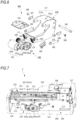
- FIG. 7 shows an internal configuration of the staple removing device 1 including a left frame 112, a right frame 114, a front frame 116 and a rear frame 117.
- FIG. 8 is an exploded perspective view of the staple removing device 1 shown in FIG. 7 .
- the left frame 112, the right frame 114, the front frame 116 and the rear frame 117 are erected on outer peripheral parts of the staple pulling mechanism 110 and the sheet pressing mechanism 160 so as to surround the same.
- the left frame 112 is erected on a left side of the staple pullout mechanism 110.
- a guide groove 113 extending along the moving direction (longitudinal direction of the housing 100) ahead of or behind the removing part 120 is formed in an upper portion of the left frame 112.
- the guide groove 113 includes a first groove 113a for locating, below the placing table 102, the tip end portion 122s of the wedge plate 122 of the removing part 120 standing by at the standby position L1, and a second groove 113b for moving the tip end portion 122s of the wedge plate 122 of the removing part 120 in a state of protruding from the placing table 102 until passing through the removal position L2 from a front of the removal position L2.
- the second groove 113b is formed at a position slightly lower than the first groove 113a via a step portion 113c.
- the left end portions of the first drive shaft 136 and the second drive shaft 138 of the removing part 120 are inserted in the guide groove 113. Thereby, the removing part 120 can move along the guide groove 113, and can move forward and rearward along the placing table 102.
- the right frame 114 is erected on a right side of the staple pullout mechanism 110.
- a guide groove 115 extending along the moving direction (longitudinal direction of the housing 100) ahead of or behind the removing part 120 is formed in an upper portion of the right frame 114.
- the guide groove 115 includes a first groove 115a for locating, below the placing table 102, the tip end portion 122s of the wedge plate 122 of the removing part 120 standing by at the standby position L1, and a second groove 115b for moving the tip end portion 122s of the wedge plate 122 of the removing part 120 in a state of protruding from the placing table 102 until passing through the removal position L2 from a front of the removal position L2.
- the second groove 115b is formed at a position slightly lower than the first groove 115a via a step portion 115c.
- the right end portions of the first drive shaft 136 and the second drive shaft 138 of the removing part 120 are inserted in the guide groove 115. Thereby, the removing part 120 can move along the guide groove 115, and can move forward and rearward along the placing table 102.
- the front frame 116 is erected on a front side of the staple pulling mechanism 110, and the rear frame 117 is erected on a rear side of the sheet pressing mechanism 160.
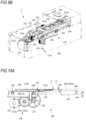
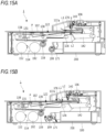
- FIG. 9A is a perspective view showing an operation of the staple pullout mechanism 110 located at the standby position L1
- FIG. 9B is a perspective view showing an operation of the staple pullout mechanism 110 moving to the removal position L2.
- FIG. 10A is a side view of main parts showing the operation of the staple pullout mechanism 110 located at the standby position L1
- FIG. 10B is a side view of main parts showing the operation of the staple pullout mechanism moving to the removal position L2.
- FIG. 11A is a side view showing the operation of the staple pullout mechanism 110 located at the standby position L1
- FIG. 11B is a side view of main parts showing the operation of the staple pullout mechanism 110 shown in FIG. 11A .
- FIG. 11A is a side view showing the operation of the staple pullout mechanism 110 located at the standby position L1
- FIG. 11B is a side view of main parts showing the operation of the staple pullout mechanism 110 shown in FIG. 11A .
- FIG. 12A is a side view showing the operation of the staple pullout mechanism 110 moving to the removal position L2
- FIG. 12B is a side view of main parts showing the operation of the staple pullout mechanism 110 shown in FIG. 12A .
- the wedge plate 122 When the staple removing device 1 is in a standby state, the wedge plate 122 is stopped at the standby position L1 of the housing 100, as shown in FIGS. 9A , 10A and 11A .
- the second drive shaft 138 is located in the first groove 113a of the guide groove 113 of the left frame 112, and the first drive shaft 136 is located in the second groove 113b of the guide groove 113 of the left frame 112.
- the attaching portion 122b-side of the wedge plate 122 is in a lifted state, and the wedge plate main body 122a-side including the tip end portion 122s of the wedge plate 122 is at a position lower than the attaching portion 122b-side.
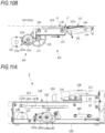
- the first motor 152 When the start switch 106 of the staple removing device 1 is operated, as shown in FIGS. 9B and 10B , the first motor 152 is driven, and the drive force of the first motor 152 is transmitted to the pinions 158 and 159 via the plurality of gears 153a, 153b, 154a, 154b and 155.
- the pinions 158 and 159 rotate in a clockwise direction in FIG. 10B , and the racks 130 and 131 in mesh with the pinions 158 and 159 move rearward from the front along the placing table 102, so that the wedge plate 122 moves rearward from the front.
- the second drive shaft 138 moves from the first groove 113a of the guide groove 113 of the left frame 112 to the second groove 113b. For this reason, the position of the wedge plate 122 on the attaching portion 122b-side is lowered, so that the wedge plate main body 122a-side of the wedge plate 122 is lifted with the first drive shaft 136 as a fulcrum.
- the tip end portion 122s of the wedge plate 122 is located above the placing surface 102a of the placing table 102.
- the wedge plate 122 moves while maintaining the state of protruding from the placing surface 102a of the placing table 102 via the opening portion 102b of the placing table 102 until passing through the removal position L2 from the front of the removal position L2. Thereby, the tip end portion 122s of the wedge plate main body 122a is surely pushed between the sheet bundle P and the crown portion Sa.
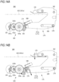
- FIG. 13A is a perspective view showing an operation of the sheet pressing mechanism 160 located at the standby position
- FIG. 13B is a perspective view showing an operation of the sheet pressing mechanism 160 moving to a pressing position
- FIG. 14A is a side view of main parts showing the operation of the sheet pressing mechanism 160 located at the standby position
- FIG. 14B is a side view of main parts showing the operation of the sheet pressing mechanism 160 moving to the pressing position.
- the sheet pressing plate 176 is stopped at a position at a certain interval from the placing surface 102a of the placing table 102.
- the certain interval is an interval at which the lower surface of the sheet pressing plate 176 does not come into contact with the uppermost sheet of the sheet bundle P placed on the placing table 102.
- the second motor 192 When the start switch of the staple removing device 1 becomes on, the second motor 192 is driven. The drive force of the second motor 192 is transmitted to the sheet pressing pinions 198 and 199 via the gears 193a, 193b, 194a, 194b and 195. Along with this, as shown in FIGS. 13B and 14B , the sheet pressing pinions 198 and 199 rotate in the clockwise direction, and the sheet pressing racks 174 and 175 in mesh with the sheet pressing pinions 198 and 199 move substantially downward.
- the hold lever 172 rotates in a counterclockwise direction with the hold lever shaft 182 as a fulcrum against the elastic force of the return spring 180, and the sheet pressing plate 176 moves (descends) in a direction toward the placing table 102.
- the sheet bundle P placed on the placing table 102 is pressed with a certain pressing force by the sheet pressing plate 176.
- the second motor 192 When the operation of removing the staple S from the sheet bundle P is over, the second motor 192 is driven in reverse rotation. Thereby, the sheet pressing plate 176 moves (ascends) in a direction away from the sheet bundle P and returns to the standby position shown in FIG. 14A and the like.
- FIGS. 15A to 15G are side views showing an example of an operation of the staple removing device 1 that is performed when pulling out the staple S from the sheet bundle Pare described.
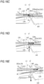
- FIGS. 16A to 16E are enlarged views of main parts showing an example of an operation of the wedge plate 122 when pulling out the staple S from the sheet bundle P.
- FIGS. 17A to 17E show states of the wedge plate 122 and the staple S when pulling out the staple S from the sheet bundle P. Note that, in the descriptions of FIG. 15A and the like, for convenience, only an operation on the right side of the staple removing device 1 is described. However, it is assumed that the left side on an opposite side can also adopt the similar operation to that of the right side.
- the sheet bundle P bound by the staple S is first placed on the placing table 102.
- a user aligns the sheet bundle P with a mark indicating the removal position L2 provided on the placing table 102, and places the crown portion Sa-side of the staple S toward the placing table.
- the sheet bundle P is bound by the staple S.
- the leg portions Sb and Sb of the staple S penetrate the sheet bundle P in the thickness direction of the sheet, are bent inwardly, and are bitten into the sheet surface.
- the second motor 192 is started to drive.
- the sheet pressing plate 176 moves (descends) in the direction toward the placing table 102, and the sheet bundle P is pressed with a certain pressing force by the sheet pressing plate 176.
- the first motor 152 is driven.
- the pinion 159 rotates in the clockwise direction, so that the removing part 120 including the rack 131 and the wedge plate 122 moves rearward from the front.
- the tip end portion 122s of the wedge plate main body 122a is located below the placing surface 102a of the placing table 102, as shown in FIG. 16A , similar to the standby position L1.
- the tip end-side of the removing part 120 moves rearward from the front ahead of the removal position L2
- the second drive shaft 138 of the removing part 120 moves to the second groove 115b of the guide groove 115. Therefore, as shown in FIG. 16B , the tip end portion 122s of the wedge plate 122 protrudes from the placing surface 102a via the opening portion 102b of the placing table 102.
- the wedge plate 122 moves rearward from the front in a state where the upper surface of the wedge plate comes into contact with a back surface of the lowermost sheet of the sheet bundle P and presses the sheet bundle P.
- the pressing portion 140 ascends due to the urging of the tension spring 144, and comes into contact with the crown portion Sa on the sheet bundle P moving rearward from the front by the pushing force of the wedge plate 122, thereby restricting the forward movement of the staple S.
- the narrowed portion 122c of the wedge plate 122 is located at the removal position L2.
- the dimension D1 in the width direction of the narrowed portion 122c of the wedge plate 122 is narrower than the dimension D3 in the width direction between the leg portions Sb and Sb of the staple S that springs back, the leg portions Sb and Sb of the staple S are separated from the side surface of the wedge plate 122, and the staple S drops into the accommodation part 200.
- the first motor 152 is driven in reverse rotation.
- the pinion 159 reversely rotates in the counterclockwise direction
- the removing part 120 including the rack 131 and the wedge plate 122 moves forward from the rear along the placing table 102, and the removing part 120 returns from the removal position L2 to the standby position L1.
- the second motor 192 is driven in reverse rotation.
- the sheet pressing pinion 199 rotates in the counterclockwise direction and the sheet pressing rack 175 moves substantially upward, so that the sheet pressing plate 176 moves in the direction away from the placing table 102 via the hold lever 172 and returns to the standby position.
- the first motor 152 and the second motor 192 are arranged directly under the removing part 120 when the wedge plate 122 of the removing part 120 is at the standby position L1.
- the part directly under the removing part 120 is a space part, specifically, an empty space part behind the accommodation part 200 formed by arranging the accommodation part 200 directly under the removing part 120 when the wedge plate 122 of the removing part 120 is at the removal position L2. For this reason, by effectively utilizing the space part behind the accommodation unit 200 and centrally arranging the first drive unit 150 including the first motor 152 and the second drive unit 190 including the second motor 192 in the space part, it is possible to suppress dimensions in the height direction and the width direction of the staple removing device 1, thereby miniaturizing the staple removing device 1.
- the accommodation part 200 is arranged directly under the removing part 120 when the wedge plate 122 of the removing part 120 is at the removal position L2. Therefore, the removed staple S can be dropped into the accommodation part 200, as it is. For this reason, it is not necessary to provide a mechanism such as a guide portion for guiding the removed staple S into the accommodation part 200, so that it is possible to simplify a structure of the staple removing device 1.
- the layout of the staple removing device 1 of the present embodiment is the most economical and optimized layout, the configuration is simple and the device can be miniaturized.
- the staple removing device 1 of the present embodiment can be mounted on an image forming apparatus configured to form an image on a sheet.
- the staple removing device 1 of the present embodiment may be arranged at a position adjacent to an operation panel of the image forming apparatus, or may be arranged inside the image forming apparatus or a post-processing apparatus connected to the image forming apparatus.
Landscapes
- Engineering & Computer Science (AREA)
- Mechanical Engineering (AREA)
- Portable Nailing Machines And Staplers (AREA)
Claims (9)
- Dispositif de dégrafage (1) comprenant :une table de placement (102) sur laquelle une liasse de feuilles (P) liées par une agrafe (S) est placée ;une partie de retrait (120) située au-dessous de la table de placement (102), configurée pour retirer l'agrafe (S) de la liasse de feuilles (P) placée sur la table de placement (102), et comportant une partie d'extrémité de pointe (1225) qui peut être insérée entre la liasse de feuilles (P) et l'agrafe (S) et est configurée pour être mobile le long de la table de placement (102) entre une première position (L1) et une deuxième position (L2) et pour être insérée entre la liasse de feuilles (P) et l'agrafe (S) lorsque la partie d'extrémité de pointe se déplace vers la deuxième position ;un premier moteur (152) configuré pour déplacer la partie de retrait (120) ; etune partie de logement (200) configurée pour loger l'agrafe (S) retirée par la partie de retrait (120),dans lequel le premier moteur (152) est situé au-dessous de la partie de retrait (120) lorsque la partie d'extrémité de pointe (1225) est à la première position (L1), etdans lequel la partie de logement (200) est située au-dessous de la partie de retrait (120) lorsque la partie d'extrémité de pointe (1225) est à la deuxième position,caractérisé en ce quele premier moteur (152) est situé directement sous la partie de retrait (120) lorsque la partie d'extrémité de pointe (1225) est à la première position (L1).
- Dispositif de dégrafage selon la revendication 1, dans lequel le premier moteur (152) est agencé de sorte qu'un arbre de sortie soit parallèle à la table de placement (102).
- Dispositif de dégrafage selon la revendication 1 ou 2, comprenant :une partie de pression de feuilles présentant au moins une partie située au-dessus de la table de placement (102) et configurée pour être mobile vers la table de placement (102) et pour presser la liasse de feuilles placée sur la table de placement, etun deuxième moteur (192) configuré pour déplacer la partie de pression de feuilles,dans lequel le deuxième moteur (192) est situé au-dessous de la partie de retrait (120) lorsque la partie d'extrémité de pointe (1225) est à la première position.
- Dispositif de dégrafage selon la revendication 3, dans lequel le deuxième moteur (192) est agencé de sorte qu'un arbre de sortie soit parallèle à la table de placement (102).
- Dispositif de dégrafage selon la revendication 3 ou 4, dans lequel un arbre de sortie (152a) du premier moteur (152) est agencé pour faire face à un côté opposé à un arbre de sortie (192a) du deuxième moteur (192).
- Dispositif de dégrafage selon l'une quelconque des revendications 1 à 5, dans lequel la partie de retrait (120) comporte la partie d'extrémité de pointe et présente une première partie configurée pour retirer l'agrafe (S) de la liasse de feuilles (P), une deuxième partie configurée pour recevoir une puissance du premier moteur, et une troisième partie située entre la première partie et la deuxième partie, et
dans lequel une dimension dans une direction de largeur d'au moins une partie de la troisième partie est configurée pour être inférieure à une dimension dans la direction de largeur d'une partie d'extrémité de base de la première partie. - Dispositif de dégrafage selon la revendication 6, comprenant :un boîtier dans lequel la partie de retrait (120), le premier moteur (152) et la partie de logement (200) sont prévus, etune première partie de pignons présentant une paire de pignons reliés à un arbre de sortie du premier moteur (152) via au moins un ou plusieurs engrenages et agencés à un intervalle prédéterminé dans une direction de largeur du boîtier,dans lequel la deuxième partie comprend une paire de crémaillères s'étendant dans une direction de déplacement à l'intervalle prédéterminé dans la direction de largeur et configurées pour se mettre en prise avec la paire de pignons.
- Dispositif de dégrafage selon la revendication 7, comprenant une deuxième partie de pignons présentant une paire de pignons reliés à un arbre de sortie du deuxième moteur (192) via au moins un ou plusieurs engrenages et agencés à un intervalle prédéterminé dans la direction de largeur,
dans lequel la partie de pression de feuilles comprend une paire de crémaillères (174, 175) s'étendant dans une direction de hauteur à l'intervalle prédéterminé dans la direction de largeur et configurées pour se mettre en prise avec la paire de pignons. - Dispositif de dégrafage selon l'une quelconque des revendications 3 à 8, dans lequel le deuxième moteur (192) est situé directement sous la partie de retrait (120) lorsque la partie d'extrémité de pointe (1225) est à la première position (L1).
Applications Claiming Priority (2)
| Application Number | Priority Date | Filing Date | Title |
|---|---|---|---|
| JP2019142573A JP7207220B2 (ja) | 2019-08-01 | 2019-08-01 | ステープル取り外し装置 |
| PCT/JP2020/029514 WO2021020572A1 (fr) | 2019-08-01 | 2020-07-31 | Dispositif de retrait d'agrafes |
Publications (3)
| Publication Number | Publication Date |
|---|---|
| EP4008484A1 EP4008484A1 (fr) | 2022-06-08 |
| EP4008484A4 EP4008484A4 (fr) | 2023-09-06 |
| EP4008484B1 true EP4008484B1 (fr) | 2024-11-20 |
Family
ID=74228908
Family Applications (1)
| Application Number | Title | Priority Date | Filing Date |
|---|---|---|---|
| EP20847620.0A Active EP4008484B1 (fr) | 2019-08-01 | 2020-07-31 | Dispositif de retrait d'agrafes |
Country Status (6)
| Country | Link |
|---|---|
| US (1) | US12179328B2 (fr) |
| EP (1) | EP4008484B1 (fr) |
| JP (1) | JP7207220B2 (fr) |
| CN (1) | CN114173999B (fr) |
| TW (1) | TWI833977B (fr) |
| WO (1) | WO2021020572A1 (fr) |
Families Citing this family (5)
| Publication number | Priority date | Publication date | Assignee | Title |
|---|---|---|---|---|
| TWI833978B (zh) * | 2019-08-01 | 2024-03-01 | 日商美克司股份有限公司 | 訂書針移除裝置 |
| JP7207220B2 (ja) * | 2019-08-01 | 2023-01-18 | マックス株式会社 | ステープル取り外し装置 |
| CN113858128B (zh) * | 2021-08-11 | 2024-07-12 | 安徽省无为县君睿印务有限责任公司 | 一种练习簿装订加工中质检用手动修正工装 |
| JP2024033856A (ja) | 2022-08-31 | 2024-03-13 | マックス株式会社 | ステープル取り外し装置 |
| EP4516456A1 (fr) | 2023-08-31 | 2025-03-05 | Max Co., Ltd. | Dispositif d'enlèvement d'agrafes |
Family Cites Families (23)
| Publication number | Priority date | Publication date | Assignee | Title |
|---|---|---|---|---|
| US3528643A (en) * | 1969-04-07 | 1970-09-15 | Whitney K Munson | Staple locating and removing device |
| JP2000131894A (ja) | 1998-10-22 | 2000-05-12 | Minolta Co Ltd | 綴じ部材除去装置およびこれを用いた自動原稿搬送装置 |
| JP2000210883A (ja) * | 1999-01-19 | 2000-08-02 | Mitsuo Osame | リム―バ付きホチキス |
| JP5218223B2 (ja) * | 2009-04-01 | 2013-06-26 | マックス株式会社 | 中綴じステープラ搭載フィニッシャにおける綴じ位置の位置決め機構 |
| JP5565180B2 (ja) | 2010-08-04 | 2014-08-06 | 株式会社リコー | 綴じ針除去装置および画像形成装置 |
| JP5785418B2 (ja) | 2011-03-30 | 2015-09-30 | 株式会社東芝 | 供給装置及び供給方法、画像形成装置 |
| JP5485248B2 (ja) * | 2011-11-17 | 2014-05-07 | シャープ株式会社 | 給紙装置、及びそれを備えた画像形成装置 |
| JP5861486B2 (ja) * | 2012-02-15 | 2016-02-16 | マックス株式会社 | ステープラ |
| CN203371496U (zh) * | 2013-07-10 | 2014-01-01 | 黄河科技学院 | 订书钉起钉机 |
| CN203600189U (zh) * | 2013-11-19 | 2014-05-21 | 吴江市信港纸箱厂 | 纸箱拆钉机 |
| JP5571264B1 (ja) * | 2014-02-07 | 2014-08-13 | 侑佑 ▲高▼橋 | ステープル針用リムーバ |
| JP2016101653A (ja) | 2014-11-17 | 2016-06-02 | グラドコR&D株式会社 | シート処理装置 |
| CN104589284B (zh) * | 2014-12-04 | 2016-01-20 | 同济大学 | 可回收利用订书钉的起钉器和订书机合为一体的装置 |
| JP6834292B2 (ja) * | 2016-09-23 | 2021-02-24 | マックス株式会社 | ステープル取り外し装置 |
| JP6908815B2 (ja) * | 2017-05-17 | 2021-07-28 | グラドコジャパン株式会社 | ステープル除去装置 |
| JP7058441B2 (ja) * | 2017-06-16 | 2022-04-22 | グラドコジャパン株式会社 | ステープル除去装置及び周辺機器または画像形成装置 |
| JP2019142573A (ja) | 2018-02-23 | 2019-08-29 | 凸版印刷株式会社 | 包装袋 |
| CN108855498B (zh) * | 2018-09-18 | 2023-08-08 | 上海震旦办公设备有限公司 | 一种具有剃钉结构的自动碎纸机及其剃钉方法 |
| TWI812809B (zh) * | 2018-11-13 | 2023-08-21 | 日商美克司股份有限公司 | 肘釘拆除裝置 |
| TWI833978B (zh) * | 2019-08-01 | 2024-03-01 | 日商美克司股份有限公司 | 訂書針移除裝置 |
| JP7207220B2 (ja) * | 2019-08-01 | 2023-01-18 | マックス株式会社 | ステープル取り外し装置 |
| JP7467871B2 (ja) | 2019-10-07 | 2024-04-16 | マックス株式会社 | ステープル取り外し装置 |
| US11981534B2 (en) * | 2022-01-31 | 2024-05-14 | Hewlett-Packard Development Company, L.P. | Shared media paths |
-
2019
- 2019-08-01 JP JP2019142573A patent/JP7207220B2/ja active Active
-
2020
- 2020-07-31 US US17/631,185 patent/US12179328B2/en active Active
- 2020-07-31 TW TW109125961A patent/TWI833977B/zh active
- 2020-07-31 CN CN202080055426.0A patent/CN114173999B/zh active Active
- 2020-07-31 EP EP20847620.0A patent/EP4008484B1/fr active Active
- 2020-07-31 WO PCT/JP2020/029514 patent/WO2021020572A1/fr not_active Ceased
Also Published As
| Publication number | Publication date |
|---|---|
| JP7207220B2 (ja) | 2023-01-18 |
| CN114173999A (zh) | 2022-03-11 |
| EP4008484A4 (fr) | 2023-09-06 |
| JP2021024017A (ja) | 2021-02-22 |
| EP4008484A1 (fr) | 2022-06-08 |
| TWI833977B (zh) | 2024-03-01 |
| US20220176533A1 (en) | 2022-06-09 |
| CN114173999B (zh) | 2024-09-24 |
| WO2021020572A1 (fr) | 2021-02-04 |
| US12179328B2 (en) | 2024-12-31 |
| TW202112504A (zh) | 2021-04-01 |
Similar Documents
| Publication | Publication Date | Title |
|---|---|---|
| EP4008484B1 (fr) | Dispositif de retrait d'agrafes | |
| US20130045065A1 (en) | Sheet binding device, post-processing device and image forming apparatus | |
| JP2003334770A (ja) | 電動ステープラ | |
| US12138765B2 (en) | Staple removal device | |
| EP2930133A1 (fr) | Dispositif de post-traitement de papier | |
| US7014084B2 (en) | Stapling apparatus with interconnected feeding and clinching | |
| JP5287468B2 (ja) | 挿抜機構及びブレードサーバ | |
| JP7622369B2 (ja) | ステープル取り外し装置 | |
| JP7207221B2 (ja) | ステープル取り外し装置 | |
| JP2005119246A (ja) | ステープラーのステープル脚切断機構 | |
| CN112621671A (zh) | 拆钉装置 | |
| JP2004025548A (ja) | 電動ホッチキスにおけるテーブルのロック機構 | |
| US20040134963A1 (en) | Stapler device | |
| US6918524B1 (en) | Staple attracting member for attracting jammed staples | |
| JP7351174B2 (ja) | ステープル取り外し装置 | |
| JP4029846B2 (ja) | ステープル送り装置 | |
| US20090148216A1 (en) | Finisher and image forming apparatus | |
| TWM625108U (zh) | 條碼列印機 | |
| WO2021020573A1 (fr) | Dispositif de retrait d'agrafes | |
| JP2004114354A (ja) | 電動ステープラーのセンサ装置 | |
| JP2019034507A (ja) | シート束処理装置 | |
| JP2002293074A (ja) | 補強シールの貼り付け装置 | |
| JPH01176741A (ja) | 給紙装置 |
Legal Events
| Date | Code | Title | Description |
|---|---|---|---|
| STAA | Information on the status of an ep patent application or granted ep patent |
Free format text: STATUS: THE INTERNATIONAL PUBLICATION HAS BEEN MADE |
|
| PUAI | Public reference made under article 153(3) epc to a published international application that has entered the european phase |
Free format text: ORIGINAL CODE: 0009012 |
|
| STAA | Information on the status of an ep patent application or granted ep patent |
Free format text: STATUS: REQUEST FOR EXAMINATION WAS MADE |
|
| 17P | Request for examination filed |
Effective date: 20220131 |
|
| AK | Designated contracting states |
Kind code of ref document: A1 Designated state(s): AL AT BE BG CH CY CZ DE DK EE ES FI FR GB GR HR HU IE IS IT LI LT LU LV MC MK MT NL NO PL PT RO RS SE SI SK SM TR |
|
| DAV | Request for validation of the european patent (deleted) | ||
| DAX | Request for extension of the european patent (deleted) | ||
| RIC1 | Information provided on ipc code assigned before grant |
Ipc: B25C 11/00 20060101AFI20230717BHEP |
|
| RIC1 | Information provided on ipc code assigned before grant |
Ipc: B25C 11/00 20060101AFI20230727BHEP |
|
| A4 | Supplementary search report drawn up and despatched |
Effective date: 20230803 |
|
| RIC1 | Information provided on ipc code assigned before grant |
Ipc: B25C 11/00 20060101AFI20230728BHEP |
|
| GRAP | Despatch of communication of intention to grant a patent |
Free format text: ORIGINAL CODE: EPIDOSNIGR1 |
|
| STAA | Information on the status of an ep patent application or granted ep patent |
Free format text: STATUS: GRANT OF PATENT IS INTENDED |
|
| INTG | Intention to grant announced |
Effective date: 20240712 |
|
| GRAS | Grant fee paid |
Free format text: ORIGINAL CODE: EPIDOSNIGR3 |
|
| GRAA | (expected) grant |
Free format text: ORIGINAL CODE: 0009210 |
|
| STAA | Information on the status of an ep patent application or granted ep patent |
Free format text: STATUS: THE PATENT HAS BEEN GRANTED |
|
| AK | Designated contracting states |
Kind code of ref document: B1 Designated state(s): AL AT BE BG CH CY CZ DE DK EE ES FI FR GB GR HR HU IE IS IT LI LT LU LV MC MK MT NL NO PL PT RO RS SE SI SK SM TR |
|
| REG | Reference to a national code |
Ref country code: GB Ref legal event code: FG4D |
|
| REG | Reference to a national code |
Ref country code: CH Ref legal event code: EP |
|
| REG | Reference to a national code |
Ref country code: DE Ref legal event code: R096 Ref document number: 602020041812 Country of ref document: DE |
|
| REG | Reference to a national code |
Ref country code: IE Ref legal event code: FG4D |
|
| REG | Reference to a national code |
Ref country code: LT Ref legal event code: MG9D |
|
| REG | Reference to a national code |
Ref country code: NL Ref legal event code: MP Effective date: 20241120 |
|
| PG25 | Lapsed in a contracting state [announced via postgrant information from national office to epo] |
Ref country code: PT Free format text: LAPSE BECAUSE OF FAILURE TO SUBMIT A TRANSLATION OF THE DESCRIPTION OR TO PAY THE FEE WITHIN THE PRESCRIBED TIME-LIMIT Effective date: 20250320 Ref country code: IS Free format text: LAPSE BECAUSE OF FAILURE TO SUBMIT A TRANSLATION OF THE DESCRIPTION OR TO PAY THE FEE WITHIN THE PRESCRIBED TIME-LIMIT Effective date: 20250320 Ref country code: HR Free format text: LAPSE BECAUSE OF FAILURE TO SUBMIT A TRANSLATION OF THE DESCRIPTION OR TO PAY THE FEE WITHIN THE PRESCRIBED TIME-LIMIT Effective date: 20241120 |
|
| PG25 | Lapsed in a contracting state [announced via postgrant information from national office to epo] |
Ref country code: FI Free format text: LAPSE BECAUSE OF FAILURE TO SUBMIT A TRANSLATION OF THE DESCRIPTION OR TO PAY THE FEE WITHIN THE PRESCRIBED TIME-LIMIT Effective date: 20241120 Ref country code: NL Free format text: LAPSE BECAUSE OF FAILURE TO SUBMIT A TRANSLATION OF THE DESCRIPTION OR TO PAY THE FEE WITHIN THE PRESCRIBED TIME-LIMIT Effective date: 20241120 |
|
| REG | Reference to a national code |
Ref country code: AT Ref legal event code: MK05 Ref document number: 1743167 Country of ref document: AT Kind code of ref document: T Effective date: 20241120 |
|
| PG25 | Lapsed in a contracting state [announced via postgrant information from national office to epo] |
Ref country code: BG Free format text: LAPSE BECAUSE OF FAILURE TO SUBMIT A TRANSLATION OF THE DESCRIPTION OR TO PAY THE FEE WITHIN THE PRESCRIBED TIME-LIMIT Effective date: 20241120 |
|
| PG25 | Lapsed in a contracting state [announced via postgrant information from national office to epo] |
Ref country code: ES Free format text: LAPSE BECAUSE OF FAILURE TO SUBMIT A TRANSLATION OF THE DESCRIPTION OR TO PAY THE FEE WITHIN THE PRESCRIBED TIME-LIMIT Effective date: 20241120 |
|
| PG25 | Lapsed in a contracting state [announced via postgrant information from national office to epo] |
Ref country code: NO Free format text: LAPSE BECAUSE OF FAILURE TO SUBMIT A TRANSLATION OF THE DESCRIPTION OR TO PAY THE FEE WITHIN THE PRESCRIBED TIME-LIMIT Effective date: 20250220 |
|
| PG25 | Lapsed in a contracting state [announced via postgrant information from national office to epo] |
Ref country code: AT Free format text: LAPSE BECAUSE OF FAILURE TO SUBMIT A TRANSLATION OF THE DESCRIPTION OR TO PAY THE FEE WITHIN THE PRESCRIBED TIME-LIMIT Effective date: 20241120 Ref country code: LV Free format text: LAPSE BECAUSE OF FAILURE TO SUBMIT A TRANSLATION OF THE DESCRIPTION OR TO PAY THE FEE WITHIN THE PRESCRIBED TIME-LIMIT Effective date: 20241120 Ref country code: GR Free format text: LAPSE BECAUSE OF FAILURE TO SUBMIT A TRANSLATION OF THE DESCRIPTION OR TO PAY THE FEE WITHIN THE PRESCRIBED TIME-LIMIT Effective date: 20250221 |
|
| PG25 | Lapsed in a contracting state [announced via postgrant information from national office to epo] |
Ref country code: PL Free format text: LAPSE BECAUSE OF FAILURE TO SUBMIT A TRANSLATION OF THE DESCRIPTION OR TO PAY THE FEE WITHIN THE PRESCRIBED TIME-LIMIT Effective date: 20241120 |
|
| PG25 | Lapsed in a contracting state [announced via postgrant information from national office to epo] |
Ref country code: RS Free format text: LAPSE BECAUSE OF FAILURE TO SUBMIT A TRANSLATION OF THE DESCRIPTION OR TO PAY THE FEE WITHIN THE PRESCRIBED TIME-LIMIT Effective date: 20250220 |
|
| PG25 | Lapsed in a contracting state [announced via postgrant information from national office to epo] |
Ref country code: SM Free format text: LAPSE BECAUSE OF FAILURE TO SUBMIT A TRANSLATION OF THE DESCRIPTION OR TO PAY THE FEE WITHIN THE PRESCRIBED TIME-LIMIT Effective date: 20241120 |
|
| PG25 | Lapsed in a contracting state [announced via postgrant information from national office to epo] |
Ref country code: DK Free format text: LAPSE BECAUSE OF FAILURE TO SUBMIT A TRANSLATION OF THE DESCRIPTION OR TO PAY THE FEE WITHIN THE PRESCRIBED TIME-LIMIT Effective date: 20241120 |
|
| PGFP | Annual fee paid to national office [announced via postgrant information from national office to epo] |
Ref country code: GB Payment date: 20250612 Year of fee payment: 6 |
|
| PG25 | Lapsed in a contracting state [announced via postgrant information from national office to epo] |
Ref country code: EE Free format text: LAPSE BECAUSE OF FAILURE TO SUBMIT A TRANSLATION OF THE DESCRIPTION OR TO PAY THE FEE WITHIN THE PRESCRIBED TIME-LIMIT Effective date: 20241120 |
|
| PGFP | Annual fee paid to national office [announced via postgrant information from national office to epo] |
Ref country code: FR Payment date: 20250610 Year of fee payment: 6 |
|
| PG25 | Lapsed in a contracting state [announced via postgrant information from national office to epo] |
Ref country code: RO Free format text: LAPSE BECAUSE OF FAILURE TO SUBMIT A TRANSLATION OF THE DESCRIPTION OR TO PAY THE FEE WITHIN THE PRESCRIBED TIME-LIMIT Effective date: 20241120 |
|
| PG25 | Lapsed in a contracting state [announced via postgrant information from national office to epo] |
Ref country code: SK Free format text: LAPSE BECAUSE OF FAILURE TO SUBMIT A TRANSLATION OF THE DESCRIPTION OR TO PAY THE FEE WITHIN THE PRESCRIBED TIME-LIMIT Effective date: 20241120 |
|
| PG25 | Lapsed in a contracting state [announced via postgrant information from national office to epo] |
Ref country code: CZ Free format text: LAPSE BECAUSE OF FAILURE TO SUBMIT A TRANSLATION OF THE DESCRIPTION OR TO PAY THE FEE WITHIN THE PRESCRIBED TIME-LIMIT Effective date: 20241120 |
|
| PG25 | Lapsed in a contracting state [announced via postgrant information from national office to epo] |
Ref country code: IT Free format text: LAPSE BECAUSE OF FAILURE TO SUBMIT A TRANSLATION OF THE DESCRIPTION OR TO PAY THE FEE WITHIN THE PRESCRIBED TIME-LIMIT Effective date: 20241120 |
|
| REG | Reference to a national code |
Ref country code: DE Ref legal event code: R097 Ref document number: 602020041812 Country of ref document: DE |
|
| PG25 | Lapsed in a contracting state [announced via postgrant information from national office to epo] |
Ref country code: SE Free format text: LAPSE BECAUSE OF FAILURE TO SUBMIT A TRANSLATION OF THE DESCRIPTION OR TO PAY THE FEE WITHIN THE PRESCRIBED TIME-LIMIT Effective date: 20241120 |
|
| PLBE | No opposition filed within time limit |
Free format text: ORIGINAL CODE: 0009261 |
|
| STAA | Information on the status of an ep patent application or granted ep patent |
Free format text: STATUS: NO OPPOSITION FILED WITHIN TIME LIMIT |
|
| PGFP | Annual fee paid to national office [announced via postgrant information from national office to epo] |
Ref country code: DE Payment date: 20250604 Year of fee payment: 6 |
|
| 26N | No opposition filed |
Effective date: 20250821 |
|
| REG | Reference to a national code |
Ref country code: CH Ref legal event code: H13 Free format text: ST27 STATUS EVENT CODE: U-0-0-H10-H13 (AS PROVIDED BY THE NATIONAL OFFICE) Effective date: 20260224 |
|
| PG25 | Lapsed in a contracting state [announced via postgrant information from national office to epo] |
Ref country code: LU Free format text: LAPSE BECAUSE OF NON-PAYMENT OF DUE FEES Effective date: 20250731 |
|
| REG | Reference to a national code |
Ref country code: BE Ref legal event code: MM Effective date: 20250731 |
|
| PG25 | Lapsed in a contracting state [announced via postgrant information from national office to epo] |
Ref country code: BE Free format text: LAPSE BECAUSE OF NON-PAYMENT OF DUE FEES Effective date: 20250731 |
|
| PG25 | Lapsed in a contracting state [announced via postgrant information from national office to epo] |
Ref country code: CH Free format text: LAPSE BECAUSE OF NON-PAYMENT OF DUE FEES Effective date: 20250731 |