EP4008488A1 - Dispositif de machine-outil à main - Google Patents
Dispositif de machine-outil à main Download PDFInfo
- Publication number
- EP4008488A1 EP4008488A1 EP21216030.3A EP21216030A EP4008488A1 EP 4008488 A1 EP4008488 A1 EP 4008488A1 EP 21216030 A EP21216030 A EP 21216030A EP 4008488 A1 EP4008488 A1 EP 4008488A1
- Authority
- EP
- European Patent Office
- Prior art keywords
- power tool
- intermediate shaft
- hand
- bearing
- held power
- Prior art date
- Legal status (The legal status is an assumption and is not a legal conclusion. Google has not performed a legal analysis and makes no representation as to the accuracy of the status listed.)
- Granted
Links
Images


Classifications
-
- B—PERFORMING OPERATIONS; TRANSPORTING
- B25—HAND TOOLS; PORTABLE POWER-DRIVEN TOOLS; MANIPULATORS
- B25F—COMBINATION OR MULTI-PURPOSE TOOLS NOT OTHERWISE PROVIDED FOR; DETAILS OR COMPONENTS OF PORTABLE POWER-DRIVEN TOOLS NOT PARTICULARLY RELATED TO THE OPERATIONS PERFORMED AND NOT OTHERWISE PROVIDED FOR
- B25F5/00—Details or components of portable power-driven tools not particularly related to the operations performed and not otherwise provided for
- B25F5/001—Gearings, speed selectors, clutches or the like specially adapted for rotary tools
-
- B—PERFORMING OPERATIONS; TRANSPORTING
- B25—HAND TOOLS; PORTABLE POWER-DRIVEN TOOLS; MANIPULATORS
- B25B—TOOLS OR BENCH DEVICES NOT OTHERWISE PROVIDED FOR, FOR FASTENING, CONNECTING, DISENGAGING, OR HOLDING
- B25B21/00—Portable power-driven screw or nut setting or loosening tools; Attachments for drilling apparatus serving the same purpose
-
- B—PERFORMING OPERATIONS; TRANSPORTING
- B25—HAND TOOLS; PORTABLE POWER-DRIVEN TOOLS; MANIPULATORS
- B25B—TOOLS OR BENCH DEVICES NOT OTHERWISE PROVIDED FOR, FOR FASTENING, CONNECTING, DISENGAGING, OR HOLDING
- B25B21/00—Portable power-driven screw or nut setting or loosening tools; Attachments for drilling apparatus serving the same purpose
- B25B21/02—Portable power-driven screw or nut setting or loosening tools; Attachments for drilling apparatus serving the same purpose with means for imparting impact to screwdriver blade or nut socket
-
- B—PERFORMING OPERATIONS; TRANSPORTING
- B25—HAND TOOLS; PORTABLE POWER-DRIVEN TOOLS; MANIPULATORS
- B25F—COMBINATION OR MULTI-PURPOSE TOOLS NOT OTHERWISE PROVIDED FOR; DETAILS OR COMPONENTS OF PORTABLE POWER-DRIVEN TOOLS NOT PARTICULARLY RELATED TO THE OPERATIONS PERFORMED AND NOT OTHERWISE PROVIDED FOR
- B25F5/00—Details or components of portable power-driven tools not particularly related to the operations performed and not otherwise provided for
-
- B—PERFORMING OPERATIONS; TRANSPORTING
- B25—HAND TOOLS; PORTABLE POWER-DRIVEN TOOLS; MANIPULATORS
- B25F—COMBINATION OR MULTI-PURPOSE TOOLS NOT OTHERWISE PROVIDED FOR; DETAILS OR COMPONENTS OF PORTABLE POWER-DRIVEN TOOLS NOT PARTICULARLY RELATED TO THE OPERATIONS PERFORMED AND NOT OTHERWISE PROVIDED FOR
- B25F5/00—Details or components of portable power-driven tools not particularly related to the operations performed and not otherwise provided for
- B25F5/02—Construction of casings, bodies or handles
Definitions
- a handheld power tool device with a drive unit which has at least one drive shaft, and with at least one rotary percussion mechanism, which has at least one intermediate shaft aligned at least substantially in alignment with the drive shaft, and with at least one bearing for mounting the drive shaft, has already been proposed.
- the invention is based on a hand-held power tool device with a drive unit, which has at least one drive shaft, and with at least one rotary percussion mechanism, which has at least one intermediate shaft aligned at least substantially in alignment with the drive shaft, and with at least one bearing for mounting the drive shaft.
- the bearing is arranged at least partially in a plane that intersects the intermediate shaft and runs at least essentially perpendicularly to the intermediate shaft.
- a “handheld power tool device” is to be understood in particular as at least a part, in particular a subassembly, of a handheld power tool.
- the hand-held power tool device can also include the entire hand-held power tool.
- the hand-held power tool can be designed as any machine, advantageously an electric machine, but advantageously as a rotary impact wrench.
- a "drive unit” is to be understood in particular as a unit that is provided for this purpose, in particular to convert electrical energy into kinetic energy, in particular rotational energy.
- the drive unit has in particular at least one housingless electric motor.
- the drive shaft is in particular at least partially formed by an armature shaft of the caseless electric motor.
- “Provided” should be understood to mean, in particular, specially programmed, designed and/or equipped. The fact that an object is provided for a specific function is to be understood in particular to mean that the object fulfills and/or executes this specific function in at least one application and/or operating state.
- a “rotary percussion mechanism” should be understood to mean, in particular, a percussion mechanism that is provided to convert an at least essentially continuous power output from a drive unit into an impact-shaped angular momentum.
- the rotary percussion mechanism can be designed in particular as a cam rotary percussion mechanism or as a V-groove rotary percussion mechanism.
- the rotary percussion mechanism has a planetary gear.
- a "planetary gear” is to be understood in particular as a gear which has at least one planet connected to a planet carrier, which is coupled to a ring gear in the radially outward direction and/or to a sun gear in the radially inward direction.
- the sun gear, the planet and/or the ring gear can be formed in particular by round gears or by non-round gears that are matched to one another.
- Several planetary gears can be connected in series and/or several stages can be interposed between the planet wheel and ring gear.
- a “hollow gear” is to be understood in particular as meaning a gear wheel which has a rim which is designed in the form of a cylinder jacket or in the form of an interrupted cylinder jacket.
- the rotary percussion mechanism has, in particular, a percussion mechanism cover.
- a “percussion mechanism cover” is to be understood in particular as a cover element which is intended to close the rotary percussion mechanism at least to a large extent in the direction of at least one further hand-held power tool unit, in particular in the direction of a drive unit.
- “at least to a large extent” is to be understood in particular as at least 51%, preferably at least 65% and particularly preferably at least 75%.
- the hammer mechanism cover has at least one feed-through recess, which is provided for at least a partial feed-through of at least one shaft, in particular a drive shaft.
- intermediate shaft should be understood in particular a shaft of a drive train, which in particular is arranged between a drive unit and an output shaft, in particular a hand-held power tool.
- the at least one intermediate shaft is provided for directly and/or indirectly transmitting a force and/or movement generated by the drive unit to the output shaft.
- the intermediate shaft is at least partially designed as a planet carrier of the planetary gear.
- a “bearing” is to be understood in particular as a radial bearing which is provided for supporting the drive shaft so that it can rotate relative to the intermediate shaft.
- the expression "essentially perpendicular” is intended here to define in particular an orientation of a direction relative to a reference direction, with the direction and the reference direction, viewed in particular in one plane, enclosing an angle of 90° and the angle has a maximum deviation of, in particular, less than 8 °, advantageously less than 5° and particularly advantageously less than 2°.
- the plane intersects both the intermediate shaft and the drive shaft at least essentially perpendicularly.
- the drive shaft is preferably mounted at least partially within the intermediate shaft.
- a configuration of this type makes it possible to provide a generic handheld power tool device with advantageous design properties.
- an advantageously compact design in particular an advantageously short overall length, of the rotary percussion mechanism can be achieved.
- a length of the hand-held power tool device is, for example, a maximum of 200 mm, in particular a maximum of 160 mm, in particular a maximum of 140 mm, particularly preferably a maximum of 130 mm.
- the length of the hand-held power tool device includes, in particular, the drive unit and the rotary percussion mechanism, as well as a tool holder.
- the intermediate shaft has at least one receiving recess which is provided for at least partially receiving the drive shaft.
- the receiving recess extends along an axis of rotation of the intermediate shaft.
- the drive shaft protrudes at least partially into the intermediate shaft, in particular into the receiving recess of the intermediate shaft.
- the bearing can be designed as a plain bearing and/or a roller bearing.
- the bearing is preferably designed at least partially as a roller bearing, for example as a ball bearing, roller bearing or needle bearing.
- the bearing is preferably arranged at least partially, advantageously completely, within the exceptional recess. In this way, an advantageously low-friction mounting of the drive shaft can be achieved. Furthermore, by arranging the bearing within the receiving recess, an advantageously small overall length of the rotary percussion mechanism can be achieved.
- the intermediate shaft has at least one sealing element receptacle.
- the sealing element receptacle is arranged directly on an insertion opening of the receiving recess of the intermediate shaft, which is provided for inserting a drive shaft into the intermediate shaft.
- the sealing element receptacle is provided in particular for at least partially accommodating a sealing element, in particular a sealing ring and/or a shaft sealing ring.
- the intermediate shaft has at least one sealing element arranged in the sealing element receptacle.
- the sealing element is in particular designed as a shaft sealing ring, in particular as a radial shaft sealing ring.
- the sealing element is provided in particular to seal off the rotary percussion mechanism, in particular the planetary gear of the rotary percussion mechanism, at least essentially from the environment. In this way, an advantageously reliable sealing of the rotary percussion mechanism can be achieved.
- a hand-held power tool in particular a rotary impact wrench, with at least one hand-held power tool device according to the invention is proposed.
- an advantageously compact hand-held power tool in particular an advantageously compact rotary impact wrench, can be provided.
- the hand-held power tool can have an advantageously short overall length.
- the handheld power tool device according to the invention should not be limited to the application and embodiment described above.
- the hand-held power tool device according to the invention can have a number of individual elements, components and units that differs from the number specified here in order to fulfill a function described herein.
- FIG 1 shows a handheld power tool 34a, which is designed as a rotary impact wrench, in a schematic partial sectional view.
- the hand-held power tool 34a is designed as a cordless impact wrench.
- the hand-held power tool 34a includes a handle 80 which extends perpendicularly to an axis of rotation 84a of a tool receptacle 86a of the hand-held power tool 34a provided for receiving an insert tool (not shown here).
- the handle 80a includes a battery receptacle 90a on a side 88a facing away from the hand-held power tool 34a.
- the battery receptacle 90a is intended to accommodate a battery unit 92a for supplying power to the hand-held power tool 34a.
- the hand-held power tool 34a has a hand-held power tool device 10a with a drive unit 12a and a rotary percussion mechanism 16a.
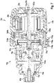
- figure 2 shows the handheld power tool device 10 in a sectional view.
- the hand-held power tool device 10a has a drive housing 72a and an impact mechanism housing 74a (cf. figure 1 ).
- the drive housing 72a encloses the drive unit 12a at least substantially completely.
- Impact mechanism housing 74a at least substantially completely encloses rotary impact mechanism 16a (cf. figure 1 ).
- the drive unit 12a is designed as an electric drive unit, which is supplied with electric energy by means of the rechargeable battery unit 92a.
- the drive unit 12a has a housingless electric motor 26a, which is intended to convert the electrical energy provided by the battery unit 92a into rotational energy.
- the electric motor 26a is designed as an open-frame motor, in which components of the electric motor 26a are mounted individually in the drive housing 72a.
- the drive unit 12a has a drive shaft 14a, which is intended to transmit the rotational energy to the rotary percussion mechanism 16a.
- the drive shaft 14a is formed entirely by an armature shaft 28a of the caseless electric motor 26a.
- the armature shaft 28a is made in one piece.
- the rotary percussion mechanism 16a is designed as a V-groove rotary percussion mechanism.
- the rotary percussion mechanism 16a is provided to convert a continuous output of power from the drive unit 12a into an impact-shaped angular momentum.
- the power of the drive unit 12a is passed on to the insert tool by means of an impact of a hammer 96a of the rotary percussion mechanism 16a on a corresponding anvil 100a of a driven spindle 15a by means of a pulse of high power intensity.
- the anvil 100a is formed in one piece with the output spindle 15a and the tool holder 86a.
- the beater 96a is mounted in such a way that an axial movement and radial movement is possible.
- the axial movement is controlled by V-shaped grooves 98a (cf. figure 3 ) and driver balls 97a (cf. figure 1 ).
- a spring 138a provides for the return movement of the striker 96a.
- the rotary percussion mechanism 16a has an intermediate shaft 18a, which is aligned at least essentially in alignment with the drive shaft 14a. Furthermore, the Hand tool device 10a at least one bearing 20a for supporting the drive shaft 14a. The bearing 20a is at least partially arranged in a plane 22a that intersects the intermediate shaft 18a and runs at least substantially perpendicularly to the intermediate shaft 18a. The drive shaft 14a is at least partially mounted within the intermediate shaft 18a.
- the intermediate shaft 18a has a receiving recess 24a, which is provided for at least partially receiving the drive shaft 14a. The receiving recess 24a extends at least essentially along a rotation axis 108a of the intermediate shaft 18a.
- the drive shaft 14a projects at least partially into the intermediate shaft 18a, in particular into the receiving recess 24a of the intermediate shaft 18a.
- the bearing 20a for supporting the drive shaft 14a is arranged within the receiving recess 24a.
- the bearing 20a for supporting the drive shaft 14a is designed as a roller bearing.
- the intermediate shaft 18a also has a sealing element receptacle 30a.
- the sealing element receptacle 30a is arranged directly on an insertion opening 136a of the receiving recess 24a of the intermediate shaft 18a, which is provided for inserting the drive shaft 14a into the intermediate shaft 18a.
- the intermediate shaft 18a has at least one sealing element 32a arranged in the sealing element receptacle 30a.
- the sealing element 32a is designed as a shaft sealing ring, in particular as a radial shaft sealing ring, which is arranged in a mounted state between the drive shaft 14a and the intermediate shaft 18a.
- the sealing element receptacle 30a is designed as a shaft sealing ring receptacle.
- Another bearing 102a for mounting the drive shaft 14a is arranged on a side 104a of the electric motor 26a facing away from the tool holder 86a in the drive housing 72a.
- the hand-held power tool device 10a has a cooling air unit 36a, which includes at least one fan wheel 38a arranged between the drive unit 12a and the rotary percussion mechanism 16a.
- the fan wheel 38a is provided in particular for generating a cooling air flow for cooling the rotary percussion mechanism 16a and/or the drive unit 12a.
- the fan wheel 38a is arranged in a torque-proof manner on the drive shaft 14a of the drive unit 12a.
- the drive unit 12a is provided to set the fan wheel 38a into a rotational movement during operation of the hand-held power tool 34a.
- the fan wheel 38a and the rotary impact mechanism 16a overlap at least partially in the axial direction 40a.
- the fan wheel 38a preferably protrudes at least partially beyond the rotary percussion mechanism 16a in the axial direction 40a.
- the fan wheel 38a has a plurality of fan wheel blades 110a arranged in the circumferential direction, which overlap at least part of the rotary percussion mechanism 16a in the circumferential direction.
- the fan wheel blades 110a extend at least essentially in the axial direction 40a.
- the rotary percussion mechanism 16a has at least one gear unit 42a designed as a single-stage planetary gear 50a.
- the bearing 20a for supporting the drive shaft 14a is arranged on a side of the planetary gear 50a facing away from the drive unit 12a.
- a toothing 144a between the drive shaft 14a and the planetary gear 50a is arranged between the bearing 20a and the bearing 102a.
- the gear unit 42a can be designed as a multi-stage planetary gear.
- the fan wheel 38a and at least the gear unit 42a preferably overlap at least partially in the axial direction 40a.
- the planetary gear 50a includes at least one ring gear 46a.
- the rotary percussion mechanism 16a includes a percussion mechanism cover 44a. Impact mechanism cover 44a is arranged between drive unit 12a and planetary gear 50a.
- the percussion mechanism cover 44a is provided to close the rotary percussion mechanism 16a in the direction of the drive unit 12a, at least to a large extent.
- Impact mechanism cover 44a has a feed-through recess 106a, which is provided for at least partial feed-through of at least drive shaft 14a.
- Impact mechanism cover 44a is formed in one piece with ring gear 46a.
- Impact mechanism cover 44a and ring gear 46a consist at least essentially of a metal material, in particular a metal sintered material.
- Fan wheel 38a and at least impact mechanism cover 44a preferably overlap at least partially in axial direction 40a.
- the hand-held power tool device 10 also has an intermediate shaft bearing 48a for supporting the intermediate shaft 18a.
- the intermediate shaft bearing 48a is designed as a roller bearing. Alternatively, the intermediate shaft bearing 48a can be designed as a slide bearing.
- the intermediate shaft bearing 48a is designed as a radial bearing, which is intended to support the intermediate shaft 18a rotatably in the hammer mechanism cover 44a.
- the intermediate shaft bearing 48a is at least partially arranged within a percussion mechanism cover 44a of the rotary percussion mechanism 16a.
- the intermediate shaft bearing 48a is arranged directly on the feed-through recess 106a of the hammer mechanism cover 44a.
- the intermediate shaft bearing 48a is arranged on the side of the impact mechanism cover 44a facing the tool holder 86a.
- Impact mechanism cover 44a has at least one bearing mount 52a, which is used to hold the Intermediate shaft bearing 48a is provided.
- the bearing mount 52a is formed in one piece with the percussion mechanism cover 44a.
- the bearing mount 52a is arranged in the area of the lead-through recess 106a of the percussion mechanism cover 44a.
- the bearing mount 52a is at least essentially designed as a hollow cylinder.
- the bearing receptacle 52a has an at least essentially ring-shaped stop element 112a for the intermediate shaft bearing 48a on an end facing away from the hammer mechanism cover 44a.
- the stop element 112a is formed in one piece with the bearing mount 52a.
- An inner diameter of the bearing seat 52a corresponds at least essentially to an outer diameter of the intermediate shaft bearing 48a.
- the intermediate shaft bearing 48a is preferably fixed in the bearing receptacle 52a by a press fit.
- the fan wheel 38a and at least the intermediate shaft bearing 48a and/or the intermediate shaft 18a preferably overlap
- FIG 3 shows the intermediate shaft 18a in a perspective view.
- figure 4 shows the intermediate shaft 18a in a sectional view along the sectional plane III-III.
- the intermediate shaft 18a is designed as a planet carrier 94a of the planetary gear 50a.
- the intermediate shaft 18a has a plurality of planet gear receptacles 54a, 56a, 58a and planet gear bearing points 60a, 62a, 64a arranged in the circumferential direction.
- a planetary gear 130a is arranged, which is rotatably mounted by means of a pin 132a.
- the intermediate shaft 18a has at least one material recess 66a, 68a, 70a on its outer circumference, at least in the area of at least one planetary wheel bearing point 60a, 62a, 64a.
- a number of material recesses 66a, 68a, 70a corresponds to a number of planet gear seats 54a, 56a, 58a.
- Exactly one material recess 66a, 68a, 70a is assigned to each planetary gear mount 54a, 56a, 58a.
- the intermediate shaft 18a has three planetary wheel mounts 54a, 56a, 58a, each with a planetary wheel bearing point 60a, 62a, 64a.
- the planetary gear bearing points 60a, 62a, 64a are arranged at least essentially offset by 120° to one another in the circumferential direction on the intermediate shaft 18a.
- the planet gear receptacles 54a, 56a, 58a are separated from one another by webs 124a extending radially to a direction of longitudinal extension 122a of the intermediate shaft 18a.
- the planetary wheel mounts 54a, 56a, 58a are delimited by two disk-shaped wall elements 126a, 128a, which are arranged at least essentially perpendicularly to the direction of longitudinal extent 122a.
- the wall elements 126a, 128a are at least essentially circular.
- the wall elements 126a, 128a are formed in one piece with the intermediate shaft 18a.
- the material recesses 66a, 68a, 70a are formed at least essentially in the shape of a segment of a circle.
- the planet wheel mounts 54a, 56a, 58a are at least essentially in the form of a cylinder segment.
- the material recesses 66a, 68a, 70a are introduced into one of the wall elements 126a, 128a.
- the material recesses 66a, 68a, 70a are introduced into the wall element 126a, which is arranged in a mounted state of the intermediate shaft 18a in the direction of a drive unit 12a.
- the wall elements 126a, 128a have an at least essentially identical radius. Alternatively, one of the wall elements 126a, 128a can have a smaller radius.
- the material recesses 66a, 68a, 70a are provided during manufacture of the intermediate shaft 18a to temporarily at least partially accommodate a milling head spindle 78a (cf. figure 5 ).
- the planet wheel mounts 54a, 56a, 58a are introduced into a blank of the intermediate shaft 18a by means of a side milling cutter 134a.
- a milling head spindle 78a of the side milling cutter 134a is at least partially inserted into a material recess 66a, 68a, 70a.
- the planet wheel mounts 54a, 56a, 58a are preferably introduced into the intermediate shaft 18a at least substantially simultaneously in a common method step, in particular by means of a plurality of identical disc milling cutters 134a.
- the side milling cutters 134a are brought up to the intermediate shaft 18a in such a way that the milling head spindles 78a run at all times at least essentially parallel to a longitudinal extension direction 122a of the intermediate shaft 18a.
- FIG 6 shows the handheld power tool 34a in a front view.
- figure 7 shows a sectional view of the handheld power tool 34a along the section line VI-VI.
- Ring gear 46a of planetary gear 50a is clamped between drive housing 72a and impact mechanism housing 74a.
- the drive housing 72a and the hammer mechanism housing 74a have a clamping surface 114a which, in a mounted state, rests on at least one surface 116a of the ring gear 46a from opposite sides and which each exert a clamping force on the ring gear 46a.
- Ring gear 46a is fixed to drive housing 72a by means of at least one screw element 76a, preferably by means of at least one screw.
- the ring gear 46a is fixed with four screw elements 76a, for example.
- Ring gear 46a has recesses 118a on an outer circumference, which are provided for passing screw elements 76a through.
- the drive housing 72a has a number of threaded recesses 120a corresponding to the number of screw elements 76a, which have a thread corresponding to a thread of the screw elements 76a.
- the drive housing 72a, the hammer mechanism housing 74a and the ring gear 46a are connected to one another in an assembled state by means of the screw elements 76a, with the ring gear 46a being arranged between the drive housing 72a and the hammer mechanism housing 74a.
- ring gear 46a can be fixed to impact mechanism housing 74a by means of at least one screw element 76a.
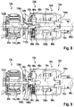
- FIG 8 shows an alternative embodiment of the handheld power tool device 10b in a sectional view.
- the hand-held power tool device 10b has a drive unit 12b and a rotary percussion mechanism 16b with a planetary gear 50b.
- the drive unit 12b has a housingless electric motor 26b, which is intended to convert electrical energy into rotational energy.
- the electric motor 26b is designed as an open-frame motor.
- the drive unit 12b has a drive shaft 14b, which is intended to transmit the rotational energy to the rotary percussion mechanism 16b.
- the drive shaft 14b is partially formed by an armature shaft 28b of the caseless electric motor 26b.
- the rotary percussion mechanism 16b has an intermediate shaft 18b which is aligned at least essentially in alignment with the drive shaft 14b. Furthermore, the hand-held power tool device 10b has at least one bearing 20b for supporting the drive shaft 14b.
- the drive shaft 14b is at least partially within the intermediate shaft 18b stored.
- the intermediate shaft 18b has a receiving recess 24b which is provided for at least partially receiving the drive shaft 14b.
- the bearing 20b is arranged directly on an insertion opening 136b of the receiving recess 24b of the intermediate shaft 18b, which is provided for inserting the drive shaft 14b into the intermediate shaft 18b.
- the bearing 20b for supporting the drive shaft 14b is arranged on a side of the planetary gear 50b facing the drive unit 12b.
- the bearing 20b is designed as a roller bearing.
- FIG 9 shows a further alternative embodiment of the handheld power tool device 10c in a sectional view.
- the hand-held power tool device 10c has a drive unit 12c and a rotary percussion mechanism 16c with a planetary gear 50c.
- the drive unit 12c has a housingless electric motor 26c, which is intended to convert electrical energy into rotational energy.
- the electric motor 26c is designed as an open-frame motor.
- the drive unit 12c has a drive shaft 14b, which is intended to transmit the rotational energy to the rotary percussion mechanism 16c.
- the drive shaft 14c is partially formed by an armature shaft 28c of the caseless electric motor 26c.
- the rotary percussion mechanism 16c has an intermediate shaft 18c, which is aligned at least essentially in alignment with the drive shaft 14c. Furthermore, the hand-held power tool device 10c has at least one bearing 20c for mounting the drive shaft 14c.
- the drive shaft 14c is at least partially mounted within the intermediate shaft 18c.
- the intermediate shaft 18c has a receiving recess 24c, which is provided for at least partially receiving the drive shaft 14c.
- the bearing 20c is arranged directly at an insertion opening 136c of the receiving recess 24c of the intermediate shaft 18c, which is provided for inserting the drive shaft 14c into the intermediate shaft 18c.
- the bearing 20c for supporting the drive shaft 14c is arranged on a side of the planetary gear 50c facing the drive unit 12c.
- the bearing 20c is designed as a ball bearing. Furthermore, the hand-held power tool device 10c has a sealing ring 140c, which encloses the bearing 20c in the circumferential direction and which is arranged between the bearing 20c and an inner diameter receiving recess 24c of the intermediate shaft 18c.
- the intermediate shaft 18c has a groove 142c which is provided for receiving the sealing ring 140c.
Landscapes
- Engineering & Computer Science (AREA)
- Mechanical Engineering (AREA)
- Drilling And Boring (AREA)
- Portable Power Tools In General (AREA)
- Shafts, Cranks, Connecting Bars, And Related Bearings (AREA)
- Retarders (AREA)
Applications Claiming Priority (4)
| Application Number | Priority Date | Filing Date | Title |
|---|---|---|---|
| DE102016212607 | 2016-07-11 | ||
| DE102017211772.9A DE102017211772A1 (de) | 2016-07-11 | 2017-07-10 | Handwerkzeugmaschinenvorrichtung |
| PCT/EP2017/067398 WO2018011203A1 (fr) | 2016-07-11 | 2017-07-11 | Système de machine-outil portative |
| EP17739956.5A EP3481593B1 (fr) | 2016-07-11 | 2017-07-11 | Système de machine-outil portative |
Related Parent Applications (2)
| Application Number | Title | Priority Date | Filing Date |
|---|---|---|---|
| EP17739956.5A Division-Into EP3481593B1 (fr) | 2016-07-11 | 2017-07-11 | Système de machine-outil portative |
| EP17739956.5A Division EP3481593B1 (fr) | 2016-07-11 | 2017-07-11 | Système de machine-outil portative |
Publications (2)
| Publication Number | Publication Date |
|---|---|
| EP4008488A1 true EP4008488A1 (fr) | 2022-06-08 |
| EP4008488B1 EP4008488B1 (fr) | 2025-05-14 |
Family
ID=60676436
Family Applications (2)
| Application Number | Title | Priority Date | Filing Date |
|---|---|---|---|
| EP21216030.3A Active EP4008488B1 (fr) | 2016-07-11 | 2017-07-11 | Dispositif de machine-outil à main |
| EP17739956.5A Active EP3481593B1 (fr) | 2016-07-11 | 2017-07-11 | Système de machine-outil portative |
Family Applications After (1)
| Application Number | Title | Priority Date | Filing Date |
|---|---|---|---|
| EP17739956.5A Active EP3481593B1 (fr) | 2016-07-11 | 2017-07-11 | Système de machine-outil portative |
Country Status (6)
| Country | Link |
|---|---|
| US (1) | US11148275B2 (fr) |
| EP (2) | EP4008488B1 (fr) |
| JP (1) | JP6916819B2 (fr) |
| CN (1) | CN109476006B (fr) |
| DE (1) | DE102017211772A1 (fr) |
| WO (1) | WO2018011203A1 (fr) |
Families Citing this family (5)
| Publication number | Priority date | Publication date | Assignee | Title |
|---|---|---|---|---|
| US20250042004A1 (en) * | 2021-12-01 | 2025-02-06 | Milwaukee Electric Tool Corporation | Rotary impact tool |
| JP7820242B2 (ja) * | 2022-06-07 | 2026-02-25 | 株式会社マキタ | インパクト工具 |
| EP4302926B1 (fr) | 2022-06-16 | 2025-08-06 | Milwaukee Electric Tool Corporation | Outil compact à percussion |
| EP4410489A1 (fr) | 2022-11-21 | 2024-08-07 | Milwaukee Electric Tool Corporation | Outil électrique à carter d'engrenage intégré |
| USD1090213S1 (en) | 2023-10-26 | 2025-08-26 | Snap-On Incorporated | Tool housing |
Citations (6)
| Publication number | Priority date | Publication date | Assignee | Title |
|---|---|---|---|---|
| EP0329852A2 (fr) * | 1988-01-23 | 1989-08-30 | Wagner, Paul-Heinz | Clé à écrous à moteur |
| DE4239799A1 (en) * | 1991-11-29 | 1993-06-03 | Ryobi Ltd | Power driven machine tool - comprises trigger operated electric motor to drive tool holder encased in housing together with heat radiation sensor |
| EP1256420A2 (fr) * | 2001-05-11 | 2002-11-13 | Johnson Electric S.A. | Motoréducteur pour outil à main |
| JP2005066804A (ja) * | 2003-08-27 | 2005-03-17 | Ryobi Ltd | 電動工具 |
| EP2368670A2 (fr) * | 2010-03-23 | 2011-09-28 | Stanley Black & Decker, Inc. | Agencement d'axe de roulement pour outil électrique |
| US20150352699A1 (en) * | 2013-01-24 | 2015-12-10 | Hitachi Koki Co., Ltd. | Power Tool |
Family Cites Families (21)
| Publication number | Priority date | Publication date | Assignee | Title |
|---|---|---|---|---|
| US2662434A (en) * | 1952-02-28 | 1953-12-15 | Millers Falis Company | Power-operated rotary impact wrench |
| US5136197A (en) | 1991-06-25 | 1992-08-04 | Clarence Hallett | Reaction containment drive for power tool |
| US5897454A (en) * | 1996-01-31 | 1999-04-27 | Black & Decker Inc. | Automatic variable transmission for power tool |
| JP2005066790A (ja) * | 2003-08-26 | 2005-03-17 | Ryobi Ltd | 電動工具 |
| JP4291173B2 (ja) * | 2004-02-10 | 2009-07-08 | 株式会社マキタ | インパクトドライバ |
| JP4405900B2 (ja) * | 2004-03-10 | 2010-01-27 | 株式会社マキタ | インパクトドライバ |
| US7308948B2 (en) * | 2004-10-28 | 2007-12-18 | Makita Corporation | Electric power tool |
| US20060237205A1 (en) * | 2005-04-21 | 2006-10-26 | Eastway Fair Company Limited | Mode selector mechanism for an impact driver |
| US8627900B2 (en) * | 2008-05-29 | 2014-01-14 | Hitachi Koki Co., Ltd. | Electric power tool |
| EP2674259B1 (fr) * | 2009-12-18 | 2017-11-01 | Techtronic Power Tools Technology Limited | Système d'outil multifonction |
| DE102011007691A1 (de) * | 2010-11-29 | 2012-05-31 | Robert Bosch Gmbh | Hammerschlagwerk |
| CN103009349A (zh) * | 2010-11-30 | 2013-04-03 | 日立工机株式会社 | 冲击工具 |
| JP5744639B2 (ja) * | 2011-06-17 | 2015-07-08 | 株式会社マキタ | 電動工具 |
| JP5744669B2 (ja) * | 2011-08-05 | 2015-07-08 | 株式会社マキタ | 電動工具 |
| DE102012208031A1 (de) | 2012-05-14 | 2013-11-14 | Robert Bosch Gmbh | +Hybrid integriertes Bauteil und Verfahren zu dessen Herstellung |
| JP6050110B2 (ja) * | 2012-12-27 | 2016-12-21 | 株式会社マキタ | インパクト工具 |
| JP6198515B2 (ja) * | 2013-08-08 | 2017-09-20 | 株式会社マキタ | インパクト工具 |
| DE102014217350B4 (de) * | 2014-08-29 | 2022-03-24 | Seg Automotive Germany Gmbh | Elektrische Maschine mit einem als Antriebslager ausgebildeten Gehäuse und darin gelagertem Hohlrad |
| JP6526533B2 (ja) | 2015-09-24 | 2019-06-05 | 株式会社マキタ | 回転打撃工具 |
| DE202016103701U1 (de) | 2016-07-11 | 2016-07-25 | Robert Bosch Gmbh | Handwerkzeugmaschinenvorrichtung |
| CN206200848U (zh) | 2016-11-04 | 2017-05-31 | 浙江意达电器有限公司 | 一种双重密封冲击扳手 |
-
2017
- 2017-07-10 DE DE102017211772.9A patent/DE102017211772A1/de not_active Withdrawn
- 2017-07-11 EP EP21216030.3A patent/EP4008488B1/fr active Active
- 2017-07-11 US US16/316,835 patent/US11148275B2/en active Active
- 2017-07-11 WO PCT/EP2017/067398 patent/WO2018011203A1/fr not_active Ceased
- 2017-07-11 CN CN201780043155.5A patent/CN109476006B/zh active Active
- 2017-07-11 EP EP17739956.5A patent/EP3481593B1/fr active Active
- 2017-07-11 JP JP2018564952A patent/JP6916819B2/ja active Active
Patent Citations (6)
| Publication number | Priority date | Publication date | Assignee | Title |
|---|---|---|---|---|
| EP0329852A2 (fr) * | 1988-01-23 | 1989-08-30 | Wagner, Paul-Heinz | Clé à écrous à moteur |
| DE4239799A1 (en) * | 1991-11-29 | 1993-06-03 | Ryobi Ltd | Power driven machine tool - comprises trigger operated electric motor to drive tool holder encased in housing together with heat radiation sensor |
| EP1256420A2 (fr) * | 2001-05-11 | 2002-11-13 | Johnson Electric S.A. | Motoréducteur pour outil à main |
| JP2005066804A (ja) * | 2003-08-27 | 2005-03-17 | Ryobi Ltd | 電動工具 |
| EP2368670A2 (fr) * | 2010-03-23 | 2011-09-28 | Stanley Black & Decker, Inc. | Agencement d'axe de roulement pour outil électrique |
| US20150352699A1 (en) * | 2013-01-24 | 2015-12-10 | Hitachi Koki Co., Ltd. | Power Tool |
Also Published As
| Publication number | Publication date |
|---|---|
| DE102017211772A1 (de) | 2018-01-11 |
| CN109476006A (zh) | 2019-03-15 |
| EP3481593B1 (fr) | 2022-01-26 |
| JP2019524457A (ja) | 2019-09-05 |
| WO2018011203A1 (fr) | 2018-01-18 |
| CN109476006B (zh) | 2022-08-30 |
| US11148275B2 (en) | 2021-10-19 |
| US20190291259A1 (en) | 2019-09-26 |
| EP4008488B1 (fr) | 2025-05-14 |
| JP6916819B2 (ja) | 2021-08-11 |
| EP3481593A1 (fr) | 2019-05-15 |
Similar Documents
| Publication | Publication Date | Title |
|---|---|---|
| EP3481594B1 (fr) | Système de machine-outil portative | |
| EP3481591B1 (fr) | Système de machine-outil portative | |
| EP3481593B1 (fr) | Système de machine-outil portative | |
| EP3481590B1 (fr) | Système de machine-outil portative | |
| EP3829819B1 (fr) | Machine-outil portative, en particulier clé à choc | |
| DE102016223678B4 (de) | Handwerkzeugmaschinenvorrichtung | |
| EP3053708B1 (fr) | Dispositif auxiliaire | |
| EP2612730B1 (fr) | Dispositif d'outil manuel | |
| DE202016103701U1 (de) | Handwerkzeugmaschinenvorrichtung | |
| DE102016214616A1 (de) | Vorsatzvorrichtung | |
| EP3332918B1 (fr) | Dispositif formant machine-outil à main | |
| EP3481596B1 (fr) | Dispositif de machine-outil portative | |
| DE102022212839A1 (de) | Handwerkzeugmaschine | |
| EP4076858A1 (fr) | Machine-outil à main comprenant une boîte de vitesses à trains planétaires | |
| EP2415558B1 (fr) | Machine de polissage tenue manuellement | |
| EP4389356A1 (fr) | Outil à main | |
| DE102022213865A1 (de) | Handwerkzeugmaschine | |
| DE102023212304A1 (de) | Handwerkzeugmaschine | |
| DE102021214919A1 (de) | Handwerkzeugmaschine | |
| DE102023212306A1 (de) | Handwerkzeugmaschine | |
| DE102022212845A1 (de) | Handwerkzeugmaschine |
Legal Events
| Date | Code | Title | Description |
|---|---|---|---|
| PUAI | Public reference made under article 153(3) epc to a published international application that has entered the european phase |
Free format text: ORIGINAL CODE: 0009012 |
|
| STAA | Information on the status of an ep patent application or granted ep patent |
Free format text: STATUS: THE APPLICATION HAS BEEN PUBLISHED |
|
| AC | Divisional application: reference to earlier application |
Ref document number: 3481593 Country of ref document: EP Kind code of ref document: P |
|
| AK | Designated contracting states |
Kind code of ref document: A1 Designated state(s): AL AT BE BG CH CY CZ DE DK EE ES FI FR GB GR HR HU IE IS IT LI LT LU LV MC MK MT NL NO PL PT RO RS SE SI SK SM TR |
|
| STAA | Information on the status of an ep patent application or granted ep patent |
Free format text: STATUS: REQUEST FOR EXAMINATION WAS MADE |
|
| 17P | Request for examination filed |
Effective date: 20221208 |
|
| RBV | Designated contracting states (corrected) |
Designated state(s): AL AT BE BG CH CY CZ DE DK EE ES FI FR GB GR HR HU IE IS IT LI LT LU LV MC MK MT NL NO PL PT RO RS SE SI SK SM TR |
|
| P01 | Opt-out of the competence of the unified patent court (upc) registered |
Effective date: 20230509 |
|
| GRAP | Despatch of communication of intention to grant a patent |
Free format text: ORIGINAL CODE: EPIDOSNIGR1 |
|
| STAA | Information on the status of an ep patent application or granted ep patent |
Free format text: STATUS: GRANT OF PATENT IS INTENDED |
|
| INTG | Intention to grant announced |
Effective date: 20250123 |
|
| GRAS | Grant fee paid |
Free format text: ORIGINAL CODE: EPIDOSNIGR3 |
|
| GRAA | (expected) grant |
Free format text: ORIGINAL CODE: 0009210 |
|
| STAA | Information on the status of an ep patent application or granted ep patent |
Free format text: STATUS: THE PATENT HAS BEEN GRANTED |
|
| AC | Divisional application: reference to earlier application |
Ref document number: 3481593 Country of ref document: EP Kind code of ref document: P |
|
| AK | Designated contracting states |
Kind code of ref document: B1 Designated state(s): AL AT BE BG CH CY CZ DE DK EE ES FI FR GB GR HR HU IE IS IT LI LT LU LV MC MK MT NL NO PL PT RO RS SE SI SK SM TR |
|
| REG | Reference to a national code |
Ref country code: GB Ref legal event code: FG4D Free format text: NOT ENGLISH |
|
| REG | Reference to a national code |
Ref country code: CH Ref legal event code: EP |
|
| REG | Reference to a national code |
Ref country code: IE Ref legal event code: FG4D Free format text: LANGUAGE OF EP DOCUMENT: GERMAN |
|
| REG | Reference to a national code |
Ref country code: DE Ref legal event code: R096 Ref document number: 502017016857 Country of ref document: DE |
|
| REG | Reference to a national code |
Ref country code: NL Ref legal event code: MP Effective date: 20250514 |
|
| PG25 | Lapsed in a contracting state [announced via postgrant information from national office to epo] |
Ref country code: PT Free format text: LAPSE BECAUSE OF FAILURE TO SUBMIT A TRANSLATION OF THE DESCRIPTION OR TO PAY THE FEE WITHIN THE PRESCRIBED TIME-LIMIT Effective date: 20250915 Ref country code: FI Free format text: LAPSE BECAUSE OF FAILURE TO SUBMIT A TRANSLATION OF THE DESCRIPTION OR TO PAY THE FEE WITHIN THE PRESCRIBED TIME-LIMIT Effective date: 20250514 Ref country code: ES Free format text: LAPSE BECAUSE OF FAILURE TO SUBMIT A TRANSLATION OF THE DESCRIPTION OR TO PAY THE FEE WITHIN THE PRESCRIBED TIME-LIMIT Effective date: 20250514 |
|
| PGFP | Annual fee paid to national office [announced via postgrant information from national office to epo] |
Ref country code: DE Payment date: 20250924 Year of fee payment: 9 |
|
| REG | Reference to a national code |
Ref country code: LT Ref legal event code: MG9D |
|
| PG25 | Lapsed in a contracting state [announced via postgrant information from national office to epo] |
Ref country code: GR Free format text: LAPSE BECAUSE OF FAILURE TO SUBMIT A TRANSLATION OF THE DESCRIPTION OR TO PAY THE FEE WITHIN THE PRESCRIBED TIME-LIMIT Effective date: 20250815 Ref country code: NO Free format text: LAPSE BECAUSE OF FAILURE TO SUBMIT A TRANSLATION OF THE DESCRIPTION OR TO PAY THE FEE WITHIN THE PRESCRIBED TIME-LIMIT Effective date: 20250814 |
|
| PG25 | Lapsed in a contracting state [announced via postgrant information from national office to epo] |
Ref country code: NL Free format text: LAPSE BECAUSE OF FAILURE TO SUBMIT A TRANSLATION OF THE DESCRIPTION OR TO PAY THE FEE WITHIN THE PRESCRIBED TIME-LIMIT Effective date: 20250514 Ref country code: PL Free format text: LAPSE BECAUSE OF FAILURE TO SUBMIT A TRANSLATION OF THE DESCRIPTION OR TO PAY THE FEE WITHIN THE PRESCRIBED TIME-LIMIT Effective date: 20250514 |
|
| PG25 | Lapsed in a contracting state [announced via postgrant information from national office to epo] |
Ref country code: BG Free format text: LAPSE BECAUSE OF FAILURE TO SUBMIT A TRANSLATION OF THE DESCRIPTION OR TO PAY THE FEE WITHIN THE PRESCRIBED TIME-LIMIT Effective date: 20250514 |
|
| PGFP | Annual fee paid to national office [announced via postgrant information from national office to epo] |
Ref country code: GB Payment date: 20250724 Year of fee payment: 9 |
|
| PG25 | Lapsed in a contracting state [announced via postgrant information from national office to epo] |
Ref country code: HR Free format text: LAPSE BECAUSE OF FAILURE TO SUBMIT A TRANSLATION OF THE DESCRIPTION OR TO PAY THE FEE WITHIN THE PRESCRIBED TIME-LIMIT Effective date: 20250514 |
|
| PGFP | Annual fee paid to national office [announced via postgrant information from national office to epo] |
Ref country code: FR Payment date: 20250723 Year of fee payment: 9 |
|
| PG25 | Lapsed in a contracting state [announced via postgrant information from national office to epo] |
Ref country code: RS Free format text: LAPSE BECAUSE OF FAILURE TO SUBMIT A TRANSLATION OF THE DESCRIPTION OR TO PAY THE FEE WITHIN THE PRESCRIBED TIME-LIMIT Effective date: 20250814 |
|
| PG25 | Lapsed in a contracting state [announced via postgrant information from national office to epo] |
Ref country code: IS Free format text: LAPSE BECAUSE OF FAILURE TO SUBMIT A TRANSLATION OF THE DESCRIPTION OR TO PAY THE FEE WITHIN THE PRESCRIBED TIME-LIMIT Effective date: 20250914 |
|
| PG25 | Lapsed in a contracting state [announced via postgrant information from national office to epo] |
Ref country code: LV Free format text: LAPSE BECAUSE OF FAILURE TO SUBMIT A TRANSLATION OF THE DESCRIPTION OR TO PAY THE FEE WITHIN THE PRESCRIBED TIME-LIMIT Effective date: 20250514 |
|
| PG25 | Lapsed in a contracting state [announced via postgrant information from national office to epo] |
Ref country code: DK Free format text: LAPSE BECAUSE OF FAILURE TO SUBMIT A TRANSLATION OF THE DESCRIPTION OR TO PAY THE FEE WITHIN THE PRESCRIBED TIME-LIMIT Effective date: 20250514 Ref country code: SM Free format text: LAPSE BECAUSE OF FAILURE TO SUBMIT A TRANSLATION OF THE DESCRIPTION OR TO PAY THE FEE WITHIN THE PRESCRIBED TIME-LIMIT Effective date: 20250514 |
|
| PG25 | Lapsed in a contracting state [announced via postgrant information from national office to epo] |
Ref country code: CZ Free format text: LAPSE BECAUSE OF FAILURE TO SUBMIT A TRANSLATION OF THE DESCRIPTION OR TO PAY THE FEE WITHIN THE PRESCRIBED TIME-LIMIT Effective date: 20250514 |
|
| PG25 | Lapsed in a contracting state [announced via postgrant information from national office to epo] |
Ref country code: EE Free format text: LAPSE BECAUSE OF FAILURE TO SUBMIT A TRANSLATION OF THE DESCRIPTION OR TO PAY THE FEE WITHIN THE PRESCRIBED TIME-LIMIT Effective date: 20250514 |
|
| PG25 | Lapsed in a contracting state [announced via postgrant information from national office to epo] |
Ref country code: SK Free format text: LAPSE BECAUSE OF FAILURE TO SUBMIT A TRANSLATION OF THE DESCRIPTION OR TO PAY THE FEE WITHIN THE PRESCRIBED TIME-LIMIT Effective date: 20250514 Ref country code: RO Free format text: LAPSE BECAUSE OF FAILURE TO SUBMIT A TRANSLATION OF THE DESCRIPTION OR TO PAY THE FEE WITHIN THE PRESCRIBED TIME-LIMIT Effective date: 20250514 |
|
| PG25 | Lapsed in a contracting state [announced via postgrant information from national office to epo] |
Ref country code: IT Free format text: LAPSE BECAUSE OF FAILURE TO SUBMIT A TRANSLATION OF THE DESCRIPTION OR TO PAY THE FEE WITHIN THE PRESCRIBED TIME-LIMIT Effective date: 20250514 |
|
| REG | Reference to a national code |
Ref country code: DE Ref legal event code: R097 Ref document number: 502017016857 Country of ref document: DE |
|
| REG | Reference to a national code |
Ref country code: CH Ref legal event code: H13 Free format text: ST27 STATUS EVENT CODE: U-0-0-H10-H13 (AS PROVIDED BY THE NATIONAL OFFICE) Effective date: 20260224 |
|
| PG25 | Lapsed in a contracting state [announced via postgrant information from national office to epo] |
Ref country code: LU Free format text: LAPSE BECAUSE OF NON-PAYMENT OF DUE FEES Effective date: 20250711 |
|
| PLBE | No opposition filed within time limit |
Free format text: ORIGINAL CODE: 0009261 |
|
| STAA | Information on the status of an ep patent application or granted ep patent |
Free format text: STATUS: NO OPPOSITION FILED WITHIN TIME LIMIT |
|
| REG | Reference to a national code |
Ref country code: CH Ref legal event code: L10 Free format text: ST27 STATUS EVENT CODE: U-0-0-L10-L00 (AS PROVIDED BY THE NATIONAL OFFICE) Effective date: 20260325 |
|
| REG | Reference to a national code |
Ref country code: BE Ref legal event code: MM Effective date: 20250731 |
|
| PG25 | Lapsed in a contracting state [announced via postgrant information from national office to epo] |
Ref country code: BE Free format text: LAPSE BECAUSE OF NON-PAYMENT OF DUE FEES Effective date: 20250731 |
|
| 26N | No opposition filed |
Effective date: 20260217 |
|
| PG25 | Lapsed in a contracting state [announced via postgrant information from national office to epo] |
Ref country code: CH Free format text: LAPSE BECAUSE OF NON-PAYMENT OF DUE FEES Effective date: 20250731 |