EP4008510A1 - Procédé de pulvérisation d'un liant liquide et dispositif de collage - Google Patents
Procédé de pulvérisation d'un liant liquide et dispositif de collage Download PDFInfo
- Publication number
- EP4008510A1 EP4008510A1 EP21206932.2A EP21206932A EP4008510A1 EP 4008510 A1 EP4008510 A1 EP 4008510A1 EP 21206932 A EP21206932 A EP 21206932A EP 4008510 A1 EP4008510 A1 EP 4008510A1
- Authority
- EP
- European Patent Office
- Prior art keywords
- component
- hardener
- nozzle
- inlet
- binder
- Prior art date
- Legal status (The legal status is an assumption and is not a legal conclusion. Google has not performed a legal analysis and makes no representation as to the accuracy of the status listed.)
- Granted
Links
Images

Classifications
-
- B—PERFORMING OPERATIONS; TRANSPORTING
- B05—SPRAYING OR ATOMISING IN GENERAL; APPLYING FLUENT MATERIALS TO SURFACES, IN GENERAL
- B05B—SPRAYING APPARATUS; ATOMISING APPARATUS; NOZZLES
- B05B7/00—Spraying apparatus for discharge of liquids or other fluent materials from two or more sources, e.g. of liquid and air, of powder and gas
- B05B7/02—Spray pistols; Apparatus for discharge
- B05B7/06—Spray pistols; Apparatus for discharge with at least one outlet orifice surrounding another approximately in the same plane
- B05B7/062—Spray pistols; Apparatus for discharge with at least one outlet orifice surrounding another approximately in the same plane with only one liquid outlet and at least one gas outlet
- B05B7/066—Spray pistols; Apparatus for discharge with at least one outlet orifice surrounding another approximately in the same plane with only one liquid outlet and at least one gas outlet with an inner liquid outlet surrounded by at least one annular gas outlet
-
- B—PERFORMING OPERATIONS; TRANSPORTING
- B05—SPRAYING OR ATOMISING IN GENERAL; APPLYING FLUENT MATERIALS TO SURFACES, IN GENERAL
- B05B—SPRAYING APPARATUS; ATOMISING APPARATUS; NOZZLES
- B05B7/00—Spraying apparatus for discharge of liquids or other fluent materials from two or more sources, e.g. of liquid and air, of powder and gas
- B05B7/02—Spray pistols; Apparatus for discharge
- B05B7/08—Spray pistols; Apparatus for discharge with separate outlet orifices, e.g. to form parallel jets, i.e. the axis of the jets being parallel, to form intersecting jets, i.e. the axis of the jets converging but not necessarily intersecting at a point
-
- B—PERFORMING OPERATIONS; TRANSPORTING
- B27—WORKING OR PRESERVING WOOD OR SIMILAR MATERIAL; NAILING OR STAPLING MACHINES IN GENERAL
- B27N—MANUFACTURE BY DRY PROCESSES OF ARTICLES, WITH OR WITHOUT ORGANIC BINDING AGENTS, MADE FROM PARTICLES OR FIBRES CONSISTING OF WOOD OR OTHER LIGNOCELLULOSIC OR LIKE ORGANIC MATERIAL
- B27N1/00—Pretreatment of moulding material
- B27N1/02—Mixing the material with binding agent
-
- B—PERFORMING OPERATIONS; TRANSPORTING
- B27—WORKING OR PRESERVING WOOD OR SIMILAR MATERIAL; NAILING OR STAPLING MACHINES IN GENERAL
- B27N—MANUFACTURE BY DRY PROCESSES OF ARTICLES, WITH OR WITHOUT ORGANIC BINDING AGENTS, MADE FROM PARTICLES OR FIBRES CONSISTING OF WOOD OR OTHER LIGNOCELLULOSIC OR LIKE ORGANIC MATERIAL
- B27N1/00—Pretreatment of moulding material
- B27N1/02—Mixing the material with binding agent
- B27N1/029—Feeding; Proportioning; Controlling
-
- B—PERFORMING OPERATIONS; TRANSPORTING
- B27—WORKING OR PRESERVING WOOD OR SIMILAR MATERIAL; NAILING OR STAPLING MACHINES IN GENERAL
- B27N—MANUFACTURE BY DRY PROCESSES OF ARTICLES, WITH OR WITHOUT ORGANIC BINDING AGENTS, MADE FROM PARTICLES OR FIBRES CONSISTING OF WOOD OR OTHER LIGNOCELLULOSIC OR LIKE ORGANIC MATERIAL
- B27N3/00—Manufacture of substantially flat articles, e.g. boards, from particles or fibres
- B27N3/08—Moulding or pressing
- B27N3/18—Auxiliary operations, e.g. preheating, humidifying, cutting-off
-
- B—PERFORMING OPERATIONS; TRANSPORTING
- B05—SPRAYING OR ATOMISING IN GENERAL; APPLYING FLUENT MATERIALS TO SURFACES, IN GENERAL
- B05B—SPRAYING APPARATUS; ATOMISING APPARATUS; NOZZLES
- B05B13/00—Machines or plants for applying liquids or other fluent materials to surfaces of objects or other work by spraying, not covered by groups B05B1/00 - B05B11/00
- B05B13/02—Means for supporting work; Arrangement or mounting of spray heads; Adaptation or arrangement of means for feeding work
- B05B13/0207—Means for supporting work; Arrangement or mounting of spray heads; Adaptation or arrangement of means for feeding work the work being an elongated body, e.g. wire or pipe
-
- B—PERFORMING OPERATIONS; TRANSPORTING
- B05—SPRAYING OR ATOMISING IN GENERAL; APPLYING FLUENT MATERIALS TO SURFACES, IN GENERAL
- B05B—SPRAYING APPARATUS; ATOMISING APPARATUS; NOZZLES
- B05B7/00—Spraying apparatus for discharge of liquids or other fluent materials from two or more sources, e.g. of liquid and air, of powder and gas
- B05B7/02—Spray pistols; Apparatus for discharge
- B05B7/12—Spray pistols; Apparatus for discharge designed to control volume of flow, e.g. with adjustable passages
- B05B7/1254—Spray pistols; Apparatus for discharge designed to control volume of flow, e.g. with adjustable passages the controlling means being fluid actuated
- B05B7/1263—Spray pistols; Apparatus for discharge designed to control volume of flow, e.g. with adjustable passages the controlling means being fluid actuated pneumatically actuated
Definitions
- the invention relates to a method for spraying a liquid binder using an atomization medium, the binder being composed of a binder component and a hardener component, with a multi-component nozzle having a nozzle body, the binder and the atomization medium being fed to the nozzle body and via at least one outlet side Nozzle opening are sprayed.
- the invention preferably relates to a method for spraying scatterable particles with a liquid binder, e.g. a method for gluing the scatterable particles.
- the multi-component nozzle used in such a method is preferably designed as a two-component nozzle for atomizing a liquid binder with the aid of an atomizing medium.
- a multi-component nozzle for example a two-component nozzle, is particularly preferred for the gluing of scatterable particles, for example in the wood-based panel industry, so that the gluing of lignocellulose-containing particles, for example wood fibers, wood chips or the like, is in the foreground.
- the atomizing medium can preferably be air, in particular compressed air. Alternatively, another gas or a vapor, for example steam, or a vapor/air mixture can also be used as the atomization medium.
- particles eg wood chips, wood fibers or the like are made available or produced as the starting material and then glued, ie provided with a liquid binder.
- a mat of grit for example, is then produced from the glued particle, which is pressed in a press to form a wood-based panel.
- the presses can be used as cycle presses or can also be designed as continuously operating presses.
- the gluing of the fibers is of particular importance in the production of wood-based panels. This is because the properties of the wood-based panel produced, eg its transverse tensile strength, depend decisively on the quality of the gluing, eg on the amount of glue used.
- suitable glues or liquid binders or binder components are e.g. B. based on polyamines or tannins.
- these binders or binder components are usually processed with a hardener or a hardener component, which is a component or an adhesive constituent that brings about crosslinking of the adhesive/binder.
- the urea-formaldehyde binders used can be, for example, solutions for lowering the pH value to initiate polycondensation reactions, for example ammonium sulfate, ammonium nitrate or ammonium chloride.
- Different hardeners, which can also be referred to as activators, are used for the different types of binders.
- gluing devices can be used for gluing, each of which is designed with one or more multi-component nozzles, in particular two-component nozzles, for spraying the glue with the aid of an atomizing medium. It can, for example, be devices for blow-line gluing. Alternatively, devices for mixer gluing can be used. Furthermore, such a device can also be designed for a chute gluing.
- the DE 10 2009 057 916 B4 describes a device and a method for continuously mixing fibers with a binder for the production of fiberboards, in which one or more rotating mixer shafts with mixing tools attached thereto are arranged in a drum-like mixing chamber, the mixing tools mixing the fibers with a binder and in a Convey in the direction of conveyance through the mixing chamber.
- a blow-line gluing in which the particles to be glued are transported through a blast line to which several nozzles opening into the blast line are connected, these nozzles being designed as multi-component nozzles, eg two-component nozzles for steam atomization.
- At least one glue supply line and one steam supply line are connected to each two-component nozzle, with at least one glue valve and one flow measuring device being integrated into the glue supply line, and with the glue valves and the flow measuring device being connected to at least one control and/or regulating device, so that the Glue valves, the flow rate for each glue supply line can be controlled or regulated separately.
- the DE 10 2019 110 188 A1 a multi-substance nozzle, in particular a two-substance nozzle, in which the nozzle needle, which is already present and can be displaced in the longitudinal direction, can not only be used as a closing and cleaning needle, but can also be used to control or regulate the flow rate of the liquid, in particular the glue, so that over the displacement of the nozzle needle in the longitudinal direction of the liquid ejection can be varied.
- the binders used are generally binders which are composed of a binder component and a hardener component.
- the binder component itself is often referred to as the binder and the hardener component as the hardener.
- the binder e.g. the glue
- the hardener or the hardener component is a component or a binder fraction that brings about crosslinking of the binder. Consequently, a two-component reaction system can be realized.
- the hardener can, for example, initiate a polymerisation reaction or initiate a polycondensation reaction, e.g. by lowering the pH value.
- the hardeners can be activators for the initiation of a radical chain polymerization.
- the hardener (regardless of the binder component) is added via a separate nozzle directly into the gluing chamber of a gluing device as an alternative.
- a separate hardener nozzle can be provided in the gluing chamber, which sprays the glue separately into the gluing chamber. This reliably prevents glue from hardening in the feed systems and in the two-component nozzles for the glue.
- the disadvantage here is that the glue consumption increases, since the hardener is no longer mixed directly with the glue, but is first fed into the gluing chamber via a separate nozzle.
- an even distribution of the hardener to the particles to be glued, e.g. the chips or the fibers cannot be achieved to the desired extent.
- the DE 10 2013 104 652 A1 a device and a method for gluing chips in a mixing device or in a transport pipe, a nozzle for supplying a binding agent being connected to the mixing device or the transport pipe.
- the binder can be mixed with steam in a mixing space of the nozzle to form a steam-binder mixture and the steam-binder mixture is dissolved in a transport pipe or a mixing device via an opening and brought into contact with the fibers and/or the chips.
- the hardener for the binder can be metered into the steam line or into the mixing room.
- the object of the invention is to create a method with which a liquid binder can be sprayed in an economical manner without malfunctions occurring in the components involved, e.g. due to sticking or curing of the binder.
- the invention teaches in a generic method of the type described above that the hardener component or the hardener (only) is mixed with the binder component when or after it exits the nozzle opening (outside the nozzle body).
- This can be achieved in a particularly preferred manner in that the hardener component is first added to the atomization medium or is mixed with the atomization medium and that the binder component is (subsequently) sprayed by means of the atomization medium to which the hardener has been added.
- the invention is based on the finding that when using two-component binders or binders that are processed with a hardener/activator, it is advantageous to use both the binder component and the hardener with one and the same nozzle, i.e. preferably a two-substance nozzle, as this reduces the glue consumption on the one hand and achieves an even distribution of the binding agent and hardener on the other.
- the supply via the same nozzle does not take place in such a way that the nozzle is supplied with a prefabricated glue or a binder-hardener mixture, but rather the binder component on the one hand and the hardener component on the other hand are fed separately to the same two-component nozzle, in such a way that mixing is particularly preferred first at or after exiting the nozzle orifice and consequently outside the nozzle body. In this way, adhesions, hardening and blockages are eliminated throughout Glue distribution system and also avoided in the nozzles. It is interesting that the multi-component nozzles known from the prior art, eg two-component nozzles, can be used within the scope of this method, for example also those from DE 10 2019 110 188 A1 known embodiments.
- the nozzle body of a multi-component nozzle has at least a first inlet for the binder or for the binder component and a second inlet for the atomizing medium.
- a binder line for supplying the (premixed) liquid binder can be connected to the first inlet, and a second line for the atomization medium is connected to the second inlet.
- it is not the (premixed) binder that is fed in via the first inlet, but only the binder component (without hardener).
- the hardener component is preferably fed in together with the atomization medium via the second inlet, e.g. via a feed line connected to the second inlet.
- the second inlet can also be suitably modified, for example, so that the hardener component is mixed with the atomization medium in the area of the second inlet, for example by connecting both a line for the atomization medium and a line for the hardener component to the second inlet.
- the hardener component can also be mixed with the atomizing medium in the area of the feed line. It is always advantageous that the hardener component is introduced into the nozzle body independently of the binder component, e.g. together with the atomizing medium.
- gluing nozzles of conventional design and to mix the hardener component with the atomizing medium as part of the supply line.
- the atomizing medium e.g. compressed air
- the hardener can therefore be added directly to the tip of the two-component nozzle together with the atomizing medium. There up If separate hardener nozzles are not used, the atomization/gluing can also be carried out particularly economically and a perfect, statistical distribution of the hardener can be achieved.
- the invention also relates to a gluing device for gluing spreadable particles, in particular lignocellulose-containing particles, with a gluing chamber into which the particles to be glued can be introduced or through which the particles to be glued can be guided and with one or more arranged in or on the gluing chamber Multi-substance nozzles, e.g. two-substance nozzles, with which the particles in the gluing chamber are sprayed with a liquid binding agent.
- a gluing device can be a gluing mixing device with a drum-like gluing chamber and one or more mixing tools rotating in the gluing chamber.
- the gluing device can be designed as a blow line gluing device (blow line) with a blow line forming the gluing chamber, to which the multicomponent nozzles are connected.
- the gluing device can also be designed as a chute gluing device, with a gluing chamber designed as a chute and with a plurality of multi-component nozzles arranged on the chute or above the chute.
- Each of the nozzles has a nozzle body with a first inlet and a second inlet and at least one nozzle opening on the outlet side, with a first line for the binder component being connected to the first inlet and a second line for the atomization medium being connected to the second inlet.
- the gluing device has a hardener line (eg as a third line) for supplying the hardener component. This can also be connected to the second inlet of the Nozzle body to be connected. Alternatively, the hardener line or third line can also be connected to the second line, so that the hardener component is initially mixed with the atomization medium in the second line via the third line.
- the supply can also take place via a third inlet in the nozzle body, ie a nozzle with a third inlet for the hardener component can be used, with the third line for the hardener component being connected to this third inlet.
- this gluing device is consequently designed in such a way that the hardener component is only mixed with the binder component in the nozzle body or during or after it emerges from the nozzle opening (for example outside the nozzle body).
- the gluing device preferably has not just a single multi-component nozzle, but rather a plurality of multi-component nozzles which are connected to the gluing chamber or protrude into the gluing chamber. Consequently, several hardener lines are preferably provided, each of which is assigned to the individual nozzles.
- the gluing device has a distribution device with which the hardener can be distributed in a desired distribution, e.g. evenly, to the individual hardener lines.
- a simple (static) multiple distributor e.g. distributor block or distributor switch
- the distribution device can also have a plurality of controllable or adjustable hardener valves, so that the hardener solution is distributed evenly or in another predetermined manner to the individual lines and thus to the individual nozzles is distributed.
- additional flow meters can be installed in the hardener lines, e.g. in each individual hardener line can be integrated so that it is then possible to control or regulate the amount of hardener in each individual hardener line.
- the amount of binder component to be sprayed can be controlled or regulated in various ways. For example, it is possible to integrate a control or regulating valve or a flow meter into the binder line, so that the amount of binder component supplied to the nozzle can be controlled or regulated. Alternatively, however, nozzles can also be used in which the ejected amount of binding agent is realized within the nozzle via a control of a nozzle needle, for example. For this purpose, reference is made to the description of the figures. In such a system, too, it is expedient to integrate a flow measuring device into the binding agent line, via which the nozzle needle is controlled or regulated.
- the gluing device according to the invention can in principle be equipped with multi-component nozzles, e.g. two-component nozzles, which are known from the prior art.
- the invention also relates to a modified multi-component nozzle, for example a two-component nozzle or three-component nozzle, which can be used, for example, for the method according to the invention or within the gluing device according to the invention.
- a multi-component nozzle can have a third inlet for the hardener component in addition to a first inlet and a second inlet, so that the binder component on the one hand and the hardener component on the other hand are supplied to the nozzle body independently of one another.
- the hardener component can be mixed with the binder component inside the nozzle body.
- the third connection is preferably designed in such a way that a The hardener component is mixed with the atomizing medium.
- the nozzle body can have a first channel for the binder component and a second channel for the atomizing medium. Both the second inlet for the atomizing medium and the third inlet for the hardener component are connected to this second channel, so that the hardener component is mixed with the atomizing medium within the second channel.
- the nozzle body can also have a third channel for the hardener component, so that the binder component, the hardener component and the atomizing medium are guided in separate channels within the nozzle body.
- the hardener component can be mixed with the binder component and/or with the atomizing medium at the end in the area of the nozzle opening.
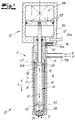
- a possible embodiment of a multi-component nozzle D for atomizing or spraying a liquid binder with the aid of an atomizing medium is shown, with this multi-component nozzle being able to be used by way of example in a method according to the invention or being part of a gluing device according to the invention, which is illustrated by way of example in 2 is shown.
- the multi-component nozzle D is designed as a two-component nozzle, with which a liquid binder, e.g. a glue or the like for the gluing of lignocellulose-containing particles in the course of the production of wood-based panels, is sprayed with an atomizing medium.
- a liquid binder e.g. a glue or the like for the gluing of lignocellulose-containing particles in the course of the production of wood-based panels.
- the atomizing medium can be, for example, air (compressed air/compressed air) or, alternatively, another gaseous medium, for example steam.
- the two-component nozzle D has a nozzle body 1, with the binding agent and the atomizing medium being fed to the nozzle body and sprayed via at least one nozzle opening 8, 9 on the outlet side.
- the nozzle body has a first inlet 10 which is connected to a first channel 6 and also a second inlet 11 which is connected to a second channel 7 .
- a hardener could be fed in via another, separate nozzle, so that a binder component without hardener was fed in via the first inlet 10 .
- the atomization medium is always supplied via the inlet 11 , with the binding agent reaching the region of the outlet opening 8 via the first channel 6 .
- the atomizing medium arrives via the second channel 7 in the region of the outlet opening 9, which annularly surrounds the outlet opening 8, so that the binder is sprayed with the aid of the atomizing medium.
- the nozzle body 1 has an outer tube 2, an inner tube 3 arranged concentrically in the outer tube 2 and a nozzle needle 4 arranged concentrically in an (axial) longitudinal direction L in the inner tube.
- a drive 5 is provided, which is designed as a pneumatic drive in the embodiment.
- An inner annular channel is provided between the nozzle needle 4 and the inner tube 3 as the first channel 6, e.g. a liquid.
- An outer annular channel 7 is provided between the outer tube 2 and the inner tube 3 as a second channel for the atomizing medium.
- the inner tube 3 has the end outlet opening 8 for the liquid, the end outlet opening 8 adjoining the inner annular channel 6 at the end.
- the two-component nozzle also has the annular opening 9 for the atomizing medium at the end, so that an annular atomizing jet hits the concentric jet of liquid on the outer circumference and scatters/sprays the liquid.
- a premixed binder (comprising binder component and hardener component) is now not fed in via the inlet opening 10, but according to the invention it is provided that the hardener component H is fed in independently of the binder component B (in the same nozzle), i.e. the hardener component H is (only) added in the Nozzle body or (only) mixed with the binder component B during or after exiting the nozzle body.
- the hardener component H is first fed to the atomization medium Z, so that the binder component B is sprayed by means of the atomization medium Z to which the hardener component H has been added.
- the inlet 10 consequently the supply of the binder component B (without hardener).
- the atomizing medium Z is fed in via the inlet 11, together with the hardener component H.
- the hardener H only comes into contact with the binder component B directly in the area of the nozzle tip or after exiting the nozzle tip outside the nozzle .
- Hardener H is therefore added with the Atomization medium Z and the binder only come together with the hardener component H outside the nozzle in the gluing chamber during the atomization process.
- a separate supply of hardener in a separate nozzle can be dispensed with, and on the other hand, blockages and contamination are prevented, since the binding agent does not harden within the nozzle D.
- an inlet socket 10a and/or an inlet line is connected to the inlet 10 and an inlet socket 11a and/or a corresponding inlet line is connected to the inlet 11.
- the binder component B is supplied via the line 10b connected to the connection piece 10a and both the atomization medium Z and the hardener component H are supplied via the line 11b connected to the connection piece 11a.
- the gluing device has a gluing chamber K, into which the particles to be glued can be introduced or through which the particles to be glued can be passed. It can be, for example, a blow line, a mixer or a chute. In the exemplary embodiment shown, six multi-component nozzles D are provided, the nozzle tips of which protrude into the gluing chamber K in order to spray the particles with the binder within the gluing chamber. A first line 10b for the binder component B and a second line 11b for the atomizing medium Z are connected to each of the nozzles D. A hardener line 22 is also provided as an additional line, via which the hardener H is supplied becomes.
- the amount of binding agent to be sprayed is controlled or regulated via the special construction of the nozzle D, specifically in connection with flow measuring devices 24 which are integrated into the binding agent lines 10b. This will be discussed further below.
- the hardener H is distributed via a distribution device 25, which is only indicated, to which the hardener lines 22 are connected.
- a distribution device 25 can be a static distribution device or a distribution block, via which the hardener reaches the individual lines and thus the individual nozzles in fixed amounts from the reservoir.
- the distribution device 25 can also have individual control or regulating valves for the individual hardener lines 22 , in which case a flow measuring device is then preferably also integrated in each case in the hardener lines 22 . This option is not shown in the figures.
- the nozzles D are each provided with a nozzle needle 4 that can be displaced along the longitudinal direction L.
- 1 shows the nozzle in the open functional position for spray operation.
- the nozzle can be moved in the closing direction S into the closed position, so that the nozzle needle 4 with its needle end 16 is moved into the outlet opening 8 in such a way that an outer closing surface 17 running around the outer circumference of the nozzle needle 4 rests against a corresponding inner closing surface 18 in the inner tube.
- This closed position is in 1 indicated by dotted lines.
- a control surface 20 formed by a control cone 19 and inclined obliquely to the nozzle axis or needle axis A can be provided on the nozzle needle 4 .
- this control cone is arranged on the side of the nozzle needle facing away from the needle end 16 in relation to the already mentioned closing surface 17, i.e. the closing surface 17 is arranged between the control cone 19 and the needle end 16.
- the control cone 19 and the inner surface 21 are oriented such that the direction of displacement of the nozzle needle 4 for closing the nozzle and consequently the closing direction S is opposite to the direction of displacement R for reducing the flow.
- the nozzle needle 4 of the nozzle can be actuated pneumatically via the pneumatic drive 5, which has a piston 13 connected to the nozzle needle 4 and guided in a cylinder 14, with the cylinder 14 and thus the piston 13 can be pressurized with a pressure medium P, e.g. with compressed air (control air), via the additionally provided compressed air connection 12a and the compressed air opening 12.
- a compressed air line is connected to the compressed air connection 12a as a control air line 32, which is also in 2 is shown. In the 2 The control air line 32 shown must therefore not be connected to the compressed air line 11b for the Atomizing medium Z are confused.
- the amount of binding agent to be sprayed is controlled or regulated - as already mentioned - by controlling the nozzle needle 4 that the control air 32 and thus the position of the nozzle needle can be controlled or regulated depending on the measurement results of the flow measuring device 24 .
- the flow measuring device 24 can also be connected to a valve 27 that is integrated into the line 11b for the atomizing medium Z, so that the supply of the atomizing medium can also be controlled or regulated depending on the measurement results of the flow measuring device 24 .
- the valves 26 and/or 27 are controllable valves, e.g. proportional valves.
- valves 28a, 28b and 28c are integrated into the binding agent supply at various points.
- Shut-off valves 29 can also be integrated into the hardener supply.
- An additional cleaning function is shown as an example, so that a cleaning medium M for cleaning the nozzles can be supplied via a cleaning line 30 .
- This cleaning line 30 opens out via three-way valves 31 into the binder lines 10b.
- nozzle is in its basic structure from the DE 10 2019 110 188 A1 known, so that this embodiment and the other embodiments described in this document are used can be. It is essential to the invention that in this embodiment not only the atomization medium Z but also the hardener H is fed in via the inlet opening 11 , independently of the binder component B, which is fed in via the inlet 10 .
- the inventive method can also be implemented with modified multi-component nozzles, for example in the 2 system shown can be used.
- the nozzle body 1 with an additional hardener inlet which, for example, can be directly connected to the channel for the atomizing medium, so that the hardener H reaches the corresponding nozzle channel for the atomizing medium inside the nozzle. this is in 1 not shown.
- an additional, third channel for the hardener as a separate hardener channel in the nozzle. This is also not shown in the figures.
Landscapes
- Life Sciences & Earth Sciences (AREA)
- Engineering & Computer Science (AREA)
- Manufacturing & Machinery (AREA)
- Wood Science & Technology (AREA)
- Forests & Forestry (AREA)
- Nozzles (AREA)
Applications Claiming Priority (1)
| Application Number | Priority Date | Filing Date | Title |
|---|---|---|---|
| DE102020132012.4A DE102020132012A1 (de) | 2020-12-02 | 2020-12-02 | Verfahren zum Versprühen eines flüssigen Bindemittels und Beleimungsvorrichtung |
Publications (3)
| Publication Number | Publication Date |
|---|---|
| EP4008510A1 true EP4008510A1 (fr) | 2022-06-08 |
| EP4008510C0 EP4008510C0 (fr) | 2026-04-22 |
| EP4008510B1 EP4008510B1 (fr) | 2026-04-22 |
Family
ID=78806252
Family Applications (1)
| Application Number | Title | Priority Date | Filing Date |
|---|---|---|---|
| EP21206932.2A Active EP4008510B1 (fr) | 2020-12-02 | 2021-11-08 | Procédé de pulvérisation d'un liant liquide et dispositif de collage |
Country Status (2)
| Country | Link |
|---|---|
| EP (1) | EP4008510B1 (fr) |
| DE (1) | DE102020132012A1 (fr) |
Citations (6)
| Publication number | Priority date | Publication date | Assignee | Title |
|---|---|---|---|---|
| DE102006013567A1 (de) * | 2006-03-24 | 2007-09-27 | Glunz Ag | Verfahren und Vorrichtung zum Aufbringen von Bindemittel auf Partikel, insbesondere Fasern, die durch einen Blasgang gefördert werden |
| DE10247412C5 (de) | 2002-10-11 | 2010-07-01 | Siempelkamp Maschinen- Und Anlagenbau Gmbh & Co. Kg | Anlage zum Beleimen von Fasern für die Herstellung von Faserplatten, insbesondere MDF-Platten und dergleichen Holzwerkstoffplatten |
| DE102011103326B4 (de) | 2011-05-27 | 2014-08-07 | Siempelkamp Maschinen- Und Anlagenbau Gmbh & Co. Kg | Vorrichtung und Verfahren zum Beleimen von Fasern |
| DE102013104652A1 (de) | 2013-05-06 | 2014-11-06 | Dieffenbacher GmbH Maschinen- und Anlagenbau | Verfahren und Vorrichtung zur Beleimung von Spänen, Fasern oder faserähnlichem Material im Zuge der Herstellung von Werkstoffplatten |
| DE102009057916B4 (de) | 2009-05-15 | 2015-04-02 | Siempelkamp Maschinen- Und Anlagenbau Gmbh | Verfahren und Vorrichtung zum kontinuierlichen Mischen von Fasern mit einem Bindemittel |
| DE102019110188A1 (de) | 2019-04-17 | 2020-10-22 | Siempelkamp Maschinen- Und Anlagenbau Gmbh | Mehrstoffdüse, insbesondere Zweistoffdüse |
Family Cites Families (2)
| Publication number | Priority date | Publication date | Assignee | Title |
|---|---|---|---|---|
| US6886618B2 (en) | 2000-03-17 | 2005-05-03 | Georgia-Pacific Resins, Inc. | System for catalyzation of thermoset resin adhesives for wood composites using computerized in-line metering and mixing equipment |
| NZ566751A (en) | 2008-03-18 | 2008-10-31 | Mdf Tech Ltd | Atomising injection nozzle |
-
2020
- 2020-12-02 DE DE102020132012.4A patent/DE102020132012A1/de active Pending
-
2021
- 2021-11-08 EP EP21206932.2A patent/EP4008510B1/fr active Active
Patent Citations (6)
| Publication number | Priority date | Publication date | Assignee | Title |
|---|---|---|---|---|
| DE10247412C5 (de) | 2002-10-11 | 2010-07-01 | Siempelkamp Maschinen- Und Anlagenbau Gmbh & Co. Kg | Anlage zum Beleimen von Fasern für die Herstellung von Faserplatten, insbesondere MDF-Platten und dergleichen Holzwerkstoffplatten |
| DE102006013567A1 (de) * | 2006-03-24 | 2007-09-27 | Glunz Ag | Verfahren und Vorrichtung zum Aufbringen von Bindemittel auf Partikel, insbesondere Fasern, die durch einen Blasgang gefördert werden |
| DE102009057916B4 (de) | 2009-05-15 | 2015-04-02 | Siempelkamp Maschinen- Und Anlagenbau Gmbh | Verfahren und Vorrichtung zum kontinuierlichen Mischen von Fasern mit einem Bindemittel |
| DE102011103326B4 (de) | 2011-05-27 | 2014-08-07 | Siempelkamp Maschinen- Und Anlagenbau Gmbh & Co. Kg | Vorrichtung und Verfahren zum Beleimen von Fasern |
| DE102013104652A1 (de) | 2013-05-06 | 2014-11-06 | Dieffenbacher GmbH Maschinen- und Anlagenbau | Verfahren und Vorrichtung zur Beleimung von Spänen, Fasern oder faserähnlichem Material im Zuge der Herstellung von Werkstoffplatten |
| DE102019110188A1 (de) | 2019-04-17 | 2020-10-22 | Siempelkamp Maschinen- Und Anlagenbau Gmbh | Mehrstoffdüse, insbesondere Zweistoffdüse |
Also Published As
| Publication number | Publication date |
|---|---|
| DE102020132012A1 (de) | 2022-06-02 |
| EP4008510C0 (fr) | 2026-04-22 |
| EP4008510B1 (fr) | 2026-04-22 |
Similar Documents
| Publication | Publication Date | Title |
|---|---|---|
| EP2621698B1 (fr) | Appareil mélangeur pour mélanges pompables et procédé s'y rapportant | |
| DE60202300T2 (de) | Niederdruck luftspritzpistole mit verbesserter sprühdüse | |
| WO2011023302A1 (fr) | Procédé et dispositif de production d'une couche pulvérisée en matière plastique réactive | |
| EP2697022A1 (fr) | Procédés permettant de faire fonctionner une installation et un dispositif pour appliquer de la colle sur des copeaux, des fibres ou des matériaux apparentés à des fibres, dans le cadre de la fabrication de panneaux de particules | |
| EP0078960B1 (fr) | Procédé d'encollage de fibres, en particulier des copeaux, et appareillage pour la mise en oeuvre de ce procédé | |
| EP3956117B1 (fr) | Buse multiple, en particulier buse double | |
| WO2004052603A1 (fr) | Installation d'encollage de fibres destinee a la production de panneaux de fibres, notamment de panneaux mdf | |
| EP3323501B1 (fr) | Dispositif et procédé destinés à l'encollage de particules | |
| EP2994277A1 (fr) | Procédé et dispositif d'encollage de copeaux, de fibres ou de matériau fibreux lors de la fabrication de panneaux | |
| EP1862214A2 (fr) | Procédé et dispositif destinés à relier des fibres dans la zone d'un tube de soufflage | |
| DE102011079982B4 (de) | Sprühkopf für reaktive Kunststoffe | |
| EP4008510B1 (fr) | Procédé de pulvérisation d'un liant liquide et dispositif de collage | |
| EP1514592A1 (fr) | Procédé et dispositif de mélange statique, en particulier pour l'encollage des fibres lignocellulosiques en utilisant un liant | |
| DE102006013567B4 (de) | Verfahren und Vorrichtung zum Aufbringen von Bindemittel auf Partikel, insbesondere Fasern, die durch einen Blasgang gefördert werden | |
| EP0110941B1 (fr) | Procede pour le melange d'un beton contenant une matiere plastique pour la realisation d'un beton projete dans un tuyau melangeur et tuyau melangeur pour la mise en oeuvre de ce procede | |
| EP2478967A1 (fr) | Soupape pour un pistolet pulvérisateur, pistolet pulvérisateur et procédé | |
| DE10023170B4 (de) | Vorrichtung zur Befeuchtung von trockenen Spritzmassen in der Förderleitung | |
| EP1543883B1 (fr) | Ensemble de soupapes pour melanger une peinture multi-composants et son procédé de fonctionnement | |
| DE10104047B4 (de) | Vorrichtung zur Trockenbeleimung von Teilchen in Form von Fasern und Spänen | |
| DE102008059334A1 (de) | Vorrichtung zum Erzeugen und Fördern eines Gas-Pulvergemisches | |
| DE3117682C2 (de) | Verfahren und Vorrichtung zum kontinuierlichen Beleimen von Holzspänen und anderen lignozellulosehaltigen Partikeln | |
| EP1054738B1 (fr) | Tete de generateur de brouillard | |
| DE3336053A1 (de) | 2-komponenten-aussenmisch-spruehpistole mit airless- und druckluftzerstaeubung | |
| DE202013101973U1 (de) | Vorrichtung zur Beleimung von Spänen, Fasern oder faserähnlichem Material im Zuge der Herstellung von Werkstoffplatten | |
| DE102004024856A1 (de) | Verfahren und Vorrichtung zum Vermischen von mehrkomponentigen Medien |
Legal Events
| Date | Code | Title | Description |
|---|---|---|---|
| PUAI | Public reference made under article 153(3) epc to a published international application that has entered the european phase |
Free format text: ORIGINAL CODE: 0009012 |
|
| STAA | Information on the status of an ep patent application or granted ep patent |
Free format text: STATUS: THE APPLICATION HAS BEEN PUBLISHED |
|
| AK | Designated contracting states |
Kind code of ref document: A1 Designated state(s): AL AT BE BG CH CY CZ DE DK EE ES FI FR GB GR HR HU IE IS IT LI LT LU LV MC MK MT NL NO PL PT RO RS SE SI SK SM TR |
|
| STAA | Information on the status of an ep patent application or granted ep patent |
Free format text: STATUS: REQUEST FOR EXAMINATION WAS MADE |
|
| 17P | Request for examination filed |
Effective date: 20220711 |
|
| RBV | Designated contracting states (corrected) |
Designated state(s): AL AT BE BG CH CY CZ DE DK EE ES FI FR GB GR HR HU IE IS IT LI LT LU LV MC MK MT NL NO PL PT RO RS SE SI SK SM TR |
|
| STAA | Information on the status of an ep patent application or granted ep patent |
Free format text: STATUS: EXAMINATION IS IN PROGRESS |
|
| 17Q | First examination report despatched |
Effective date: 20250521 |
|
| GRAP | Despatch of communication of intention to grant a patent |
Free format text: ORIGINAL CODE: EPIDOSNIGR1 |
|
| STAA | Information on the status of an ep patent application or granted ep patent |
Free format text: STATUS: GRANT OF PATENT IS INTENDED |
|
| INTG | Intention to grant announced |
Effective date: 20251208 |
|
| GRAS | Grant fee paid |
Free format text: ORIGINAL CODE: EPIDOSNIGR3 |
|
| GRAA | (expected) grant |
Free format text: ORIGINAL CODE: 0009210 |
|
| STAA | Information on the status of an ep patent application or granted ep patent |
Free format text: STATUS: THE PATENT HAS BEEN GRANTED |
|
| AK | Designated contracting states |
Kind code of ref document: B1 Designated state(s): AL AT BE BG CH CY CZ DE DK EE ES FI FR GB GR HR HU IE IS IT LI LT LU LV MC MK MT NL NO PL PT RO RS SE SI SK SM TR |
|
| REG | Reference to a national code |
Ref country code: CH Ref legal event code: F10 Free format text: ST27 STATUS EVENT CODE: U-0-0-F10-F00 (AS PROVIDED BY THE NATIONAL OFFICE) Effective date: 20260422 Ref country code: GB Ref legal event code: FG4D Free format text: NOT ENGLISH |
|
| REG | Reference to a national code |
Ref country code: DE Ref legal event code: R096 Ref document number: 502021010317 Country of ref document: DE |
|
| REG | Reference to a national code |
Ref country code: IE Ref legal event code: FG4D Free format text: LANGUAGE OF EP DOCUMENT: GERMAN |
|
| U01 | Request for unitary effect filed |
Effective date: 20260508 |
|
| U07 | Unitary effect registered |
Designated state(s): AT BE BG DE DK EE FI FR IT LT LU LV MT NL PT RO SE SI Effective date: 20260518 |