EP4008540B1 - Système et procédé de fabrication d'une structure de support - Google Patents
Système et procédé de fabrication d'une structure de support Download PDFInfo
- Publication number
- EP4008540B1 EP4008540B1 EP21211074.6A EP21211074A EP4008540B1 EP 4008540 B1 EP4008540 B1 EP 4008540B1 EP 21211074 A EP21211074 A EP 21211074A EP 4008540 B1 EP4008540 B1 EP 4008540B1
- Authority
- EP
- European Patent Office
- Prior art keywords
- inserts
- retainer plate
- core
- actuator
- set forth
- Prior art date
- Legal status (The legal status is an assumption and is not a legal conclusion. Google has not performed a legal analysis and makes no representation as to the accuracy of the status listed.)
- Active
Links
Images










Classifications
-
- B—PERFORMING OPERATIONS; TRANSPORTING
- B29—WORKING OF PLASTICS; WORKING OF SUBSTANCES IN A PLASTIC STATE IN GENERAL
- B29D—PRODUCING PARTICULAR ARTICLES FROM PLASTICS OR FROM SUBSTANCES IN A PLASTIC STATE
- B29D30/00—Producing pneumatic or solid tyres or parts thereof
- B29D30/0005—Pretreatment of tyres or parts thereof, e.g. preheating, irradiation, precuring
-
- B—PERFORMING OPERATIONS; TRANSPORTING
- B60—VEHICLES IN GENERAL
- B60C—VEHICLE TYRES; TYRE INFLATION; TYRE CHANGING; CONNECTING VALVES TO INFLATABLE ELASTIC BODIES IN GENERAL; DEVICES OR ARRANGEMENTS RELATED TO TYRES
- B60C7/00—Non-inflatable or solid tyres
- B60C7/10—Non-inflatable or solid tyres characterised by means for increasing resiliency
- B60C7/14—Non-inflatable or solid tyres characterised by means for increasing resiliency using springs
- B60C7/146—Non-inflatable or solid tyres characterised by means for increasing resiliency using springs extending substantially radially, e.g. like spokes
-
- B—PERFORMING OPERATIONS; TRANSPORTING
- B29—WORKING OF PLASTICS; WORKING OF SUBSTANCES IN A PLASTIC STATE IN GENERAL
- B29D—PRODUCING PARTICULAR ARTICLES FROM PLASTICS OR FROM SUBSTANCES IN A PLASTIC STATE
- B29D30/00—Producing pneumatic or solid tyres or parts thereof
- B29D30/02—Solid tyres ; Moulds therefor
-
- B—PERFORMING OPERATIONS; TRANSPORTING
- B29—WORKING OF PLASTICS; WORKING OF SUBSTANCES IN A PLASTIC STATE IN GENERAL
- B29D—PRODUCING PARTICULAR ARTICLES FROM PLASTICS OR FROM SUBSTANCES IN A PLASTIC STATE
- B29D30/00—Producing pneumatic or solid tyres or parts thereof
- B29D30/06—Pneumatic tyres or parts thereof (e.g. produced by casting, moulding, compression moulding, injection moulding, centrifugal casting)
- B29D30/0601—Vulcanising tyres; Vulcanising presses for tyres
- B29D30/0606—Vulcanising moulds not integral with vulcanising presses
-
- B—PERFORMING OPERATIONS; TRANSPORTING
- B29—WORKING OF PLASTICS; WORKING OF SUBSTANCES IN A PLASTIC STATE IN GENERAL
- B29C—SHAPING OR JOINING OF PLASTICS; SHAPING OF MATERIAL IN A PLASTIC STATE, NOT OTHERWISE PROVIDED FOR; AFTER-TREATMENT OF THE SHAPED PRODUCTS, e.g. REPAIRING
- B29C33/00—Moulds or cores; Details thereof or accessories therefor
- B29C33/02—Moulds or cores; Details thereof or accessories therefor with incorporated heating or cooling means
-
- B—PERFORMING OPERATIONS; TRANSPORTING
- B29—WORKING OF PLASTICS; WORKING OF SUBSTANCES IN A PLASTIC STATE IN GENERAL
- B29C—SHAPING OR JOINING OF PLASTICS; SHAPING OF MATERIAL IN A PLASTIC STATE, NOT OTHERWISE PROVIDED FOR; AFTER-TREATMENT OF THE SHAPED PRODUCTS, e.g. REPAIRING
- B29C33/00—Moulds or cores; Details thereof or accessories therefor
- B29C33/02—Moulds or cores; Details thereof or accessories therefor with incorporated heating or cooling means
- B29C33/04—Moulds or cores; Details thereof or accessories therefor with incorporated heating or cooling means using liquids, gas or steam
-
- B—PERFORMING OPERATIONS; TRANSPORTING
- B29—WORKING OF PLASTICS; WORKING OF SUBSTANCES IN A PLASTIC STATE IN GENERAL
- B29C—SHAPING OR JOINING OF PLASTICS; SHAPING OF MATERIAL IN A PLASTIC STATE, NOT OTHERWISE PROVIDED FOR; AFTER-TREATMENT OF THE SHAPED PRODUCTS, e.g. REPAIRING
- B29C33/00—Moulds or cores; Details thereof or accessories therefor
- B29C33/02—Moulds or cores; Details thereof or accessories therefor with incorporated heating or cooling means
- B29C33/04—Moulds or cores; Details thereof or accessories therefor with incorporated heating or cooling means using liquids, gas or steam
- B29C33/048—Moulds or cores; Details thereof or accessories therefor with incorporated heating or cooling means using liquids, gas or steam using steam
-
- B—PERFORMING OPERATIONS; TRANSPORTING
- B29—WORKING OF PLASTICS; WORKING OF SUBSTANCES IN A PLASTIC STATE IN GENERAL
- B29C—SHAPING OR JOINING OF PLASTICS; SHAPING OF MATERIAL IN A PLASTIC STATE, NOT OTHERWISE PROVIDED FOR; AFTER-TREATMENT OF THE SHAPED PRODUCTS, e.g. REPAIRING
- B29C35/00—Heating, cooling or curing, e.g. crosslinking or vulcanising; Apparatus therefor
- B29C35/007—Tempering units for temperature control of moulds or cores, e.g. comprising heat exchangers, controlled valves, temperature-controlled circuits for fluids
-
- B—PERFORMING OPERATIONS; TRANSPORTING
- B29—WORKING OF PLASTICS; WORKING OF SUBSTANCES IN A PLASTIC STATE IN GENERAL
- B29D—PRODUCING PARTICULAR ARTICLES FROM PLASTICS OR FROM SUBSTANCES IN A PLASTIC STATE
- B29D30/00—Producing pneumatic or solid tyres or parts thereof
- B29D30/06—Pneumatic tyres or parts thereof (e.g. produced by casting, moulding, compression moulding, injection moulding, centrifugal casting)
- B29D30/0601—Vulcanising tyres; Vulcanising presses for tyres
-
- B—PERFORMING OPERATIONS; TRANSPORTING
- B29—WORKING OF PLASTICS; WORKING OF SUBSTANCES IN A PLASTIC STATE IN GENERAL
- B29D—PRODUCING PARTICULAR ARTICLES FROM PLASTICS OR FROM SUBSTANCES IN A PLASTIC STATE
- B29D30/00—Producing pneumatic or solid tyres or parts thereof
- B29D30/06—Pneumatic tyres or parts thereof (e.g. produced by casting, moulding, compression moulding, injection moulding, centrifugal casting)
- B29D30/0601—Vulcanising tyres; Vulcanising presses for tyres
- B29D30/0662—Accessories, details or auxiliary operations
-
- B—PERFORMING OPERATIONS; TRANSPORTING
- B29—WORKING OF PLASTICS; WORKING OF SUBSTANCES IN A PLASTIC STATE IN GENERAL
- B29D—PRODUCING PARTICULAR ARTICLES FROM PLASTICS OR FROM SUBSTANCES IN A PLASTIC STATE
- B29D30/00—Producing pneumatic or solid tyres or parts thereof
- B29D30/06—Pneumatic tyres or parts thereof (e.g. produced by casting, moulding, compression moulding, injection moulding, centrifugal casting)
- B29D30/08—Building tyres
- B29D30/10—Building tyres on round cores, i.e. the shape of the core is approximately identical with the shape of the completed tyre
- B29D30/14—Rolling-down or pressing-down the layers in the building process
-
- B—PERFORMING OPERATIONS; TRANSPORTING
- B60—VEHICLES IN GENERAL
- B60B—VEHICLE WHEELS; CASTORS; AXLES FOR WHEELS OR CASTORS; INCREASING WHEEL ADHESION
- B60B27/00—Hubs
- B60B27/06—Hubs adapted to be fixed on axle
- B60B27/065—Hubs adapted to be fixed on axle characterised by the fixation of the hub to the axle
-
- B—PERFORMING OPERATIONS; TRANSPORTING
- B60—VEHICLES IN GENERAL
- B60B—VEHICLE WHEELS; CASTORS; AXLES FOR WHEELS OR CASTORS; INCREASING WHEEL ADHESION
- B60B3/00—Disc wheels, i.e. wheels with load-supporting disc body
- B60B3/10—Disc wheels, i.e. wheels with load-supporting disc body apertured to simulate spoked wheels
-
- B—PERFORMING OPERATIONS; TRANSPORTING
- B60—VEHICLES IN GENERAL
- B60B—VEHICLE WHEELS; CASTORS; AXLES FOR WHEELS OR CASTORS; INCREASING WHEEL ADHESION
- B60B9/00—Wheels of high resiliency, e.g. with conical interacting pressure-surfaces
- B60B9/26—Wheels of high resiliency, e.g. with conical interacting pressure-surfaces comprising resilient spokes
-
- B—PERFORMING OPERATIONS; TRANSPORTING
- B60—VEHICLES IN GENERAL
- B60C—VEHICLE TYRES; TYRE INFLATION; TYRE CHANGING; CONNECTING VALVES TO INFLATABLE ELASTIC BODIES IN GENERAL; DEVICES OR ARRANGEMENTS RELATED TO TYRES
- B60C7/00—Non-inflatable or solid tyres
- B60C7/10—Non-inflatable or solid tyres characterised by means for increasing resiliency
- B60C7/14—Non-inflatable or solid tyres characterised by means for increasing resiliency using springs
- B60C7/16—Non-inflatable or solid tyres characterised by means for increasing resiliency using springs of helical or flat coil form
- B60C7/18—Non-inflatable or solid tyres characterised by means for increasing resiliency using springs of helical or flat coil form disposed radially relative to wheel axis
-
- B—PERFORMING OPERATIONS; TRANSPORTING
- B60—VEHICLES IN GENERAL
- B60C—VEHICLE TYRES; TYRE INFLATION; TYRE CHANGING; CONNECTING VALVES TO INFLATABLE ELASTIC BODIES IN GENERAL; DEVICES OR ARRANGEMENTS RELATED TO TYRES
- B60C7/00—Non-inflatable or solid tyres
- B60C7/24—Non-inflatable or solid tyres characterised by means for securing tyres on rim or wheel body
-
- B—PERFORMING OPERATIONS; TRANSPORTING
- B29—WORKING OF PLASTICS; WORKING OF SUBSTANCES IN A PLASTIC STATE IN GENERAL
- B29D—PRODUCING PARTICULAR ARTICLES FROM PLASTICS OR FROM SUBSTANCES IN A PLASTIC STATE
- B29D30/00—Producing pneumatic or solid tyres or parts thereof
- B29D30/06—Pneumatic tyres or parts thereof (e.g. produced by casting, moulding, compression moulding, injection moulding, centrifugal casting)
- B29D30/0601—Vulcanising tyres; Vulcanising presses for tyres
- B29D30/0606—Vulcanising moulds not integral with vulcanising presses
- B29D2030/0607—Constructional features of the moulds
-
- B—PERFORMING OPERATIONS; TRANSPORTING
- B60—VEHICLES IN GENERAL
- B60B—VEHICLE WHEELS; CASTORS; AXLES FOR WHEELS OR CASTORS; INCREASING WHEEL ADHESION
- B60B2360/00—Materials; Physical forms thereof
- B60B2360/30—Synthetic materials
- B60B2360/32—Plastic compositions
-
- B—PERFORMING OPERATIONS; TRANSPORTING
- B60—VEHICLES IN GENERAL
- B60B—VEHICLE WHEELS; CASTORS; AXLES FOR WHEELS OR CASTORS; INCREASING WHEEL ADHESION
- B60B2900/00—Purpose of invention
- B60B2900/10—Reduction of
- B60B2900/111—Weight
-
- B—PERFORMING OPERATIONS; TRANSPORTING
- B60—VEHICLES IN GENERAL
- B60B—VEHICLE WHEELS; CASTORS; AXLES FOR WHEELS OR CASTORS; INCREASING WHEEL ADHESION
- B60B2900/00—Purpose of invention
- B60B2900/30—Increase in
- B60B2900/321—Lifetime
Definitions
- the present invention relates to wheel/tire assemblies, and more particularly, to a system and method for manufacturing non-pneumatic wheel/tire assemblies.
- Radial pneumatic tires rely on the ply reinforcement to carry and transfer the load between the rim and the belt layer. These ply cords need to be tensioned to carry the load. Tensioning of these ply cords is achieved with the pressurized air in the inner chamber of the tire. If air pressure is lost, load carrying capacity of a pneumatic tire decreases significantly. Preventing the slow or sudden air pressure loss has been a challenge for the tire makers.
- One proposed solution is to use non-pneumatic tires.
- a top loader non-pneumatic tire can perform similar to a pneumatic tire if its durability, speed rating/limit and load capacity can be increased to the levels of a pneumatic tire.
- top loader non-pneumatic tires rely on the polymeric spokes to carry the load of the vehicle. Spokes transfer the load from the rim to the shear band. Due to the characteristics of the polymeric materials used in the spokes of these tires, performance of these tires is limited. It is an object of the present invention to overcome this limitation and increase the load carrying capacity and durability of these spokes and hence the performance of the top loader non-pneumatic tire.
- US 2015/0210025 A1 discloses a removable insert for a tire mold used to manufacture a non-pneumatic tire.
- the removable insert includes a first end, a second end, a body, an inner cavity and an insert retaining feature.
- Annular means formed like a ring.
- “Circumferential” and “circumferentially” mean lines or directions extending along the perimeter of the surface of the annular tire parallel to the equatorial plane (EP) and perpendicular to the axial direction.
- “Lateral” means an axial direction.
- Ring and radially mean directions radially toward or away from the axis of rotation of the tire.
- the invention relates to a system in accordance with claim 1 and to a method in accordance with claim 7.
- the first actuator and the second actuator are configured to compress the first inserts and corresponding parts of the tire assembly together.
- the first retainer plate and the second retainer plate secure the first inserts to the core.
- the first retainer plate and the second retainer plate orient a plurality of rubber sheets of the tire assembly with the core.
- the first inserts have internal channels for contributing to the curing of parts of the tire assembly.
- the first inserts are shaped to assist shaping of parts of the tire assembly.
- internal channels of the first inserts are heated to an appropriate curing temperature for the tire assembly.
- internal channels of the first inserts are heated by a hot liquid.
- internal channels of the first inserts are heated by steam.
- internal channels of the first inserts are heated by electricity.
- the method includes a further step of heating internal channels of the larger inserts by a hot liquid.
- the method includes a further step of coaxially securing the upper retainer plate to alternating larger inserts and smaller inserts.
- the method includes a further step of radially and circumferentially securing the larger inserts and smaller inserts to the core.
- the method includes a further step of appropriately positioning the corresponding parts of the tire assembly relative to each other.
- the method includes a further step of applying heat to the core and the larger inserts.
- the method includes a further step of cooling the core and the larger inserts.
- the method includes a further step of axially releasing the upper actuator and the lower actuator.
- the method includes a further step of disengaging the upper actuator and the lower actuator from an axial placement shaft.
- the method includes a further step of revealing a cured single-piece structure made from cured together parts of the tire assembly.
- a conventional wheel/tire assembly may have an outer ring, such as a shear band, flexibly connected to a central hub by means of lightweight composite springs.
- the springs may be plates fixed to the ring and to the hub.
- the hub may contain a speed reduction gear unit and/or an electric motor and may have a suspension mechanism for connecting a vehicle chassis to each wheel.
- the ring may be constructed from a flexible composite material, such as carbon fiber reinforced nylon material and have twin rubber tires and a plurality of circumferentially spaced-apart radial cleats which engage the ground and provide improved traction.
- the hub may also be formed from a carbon fiber reinforced composite material.
- Another conventional wheel may have a rubber strip with a molded tread bonded to a composite ring for improved grip.
- the springs interconnecting the ring and hub may be S-shaped lightweight composite springs.
- Another conventional wheel/tire assembly may be formed from a lightweight composite material, such as carbon fiber reinforced polyamide.
- the assembly may have a cylindrical central hub and a circular outer flexible rim mounted on the central hub by an endless looped spring band extending between the central hub and the circular rim. Six radial loops may be defined by the spring band.
- the spring band may be attached to the central hub and to the circular rim by any suitable means, such as adhesion, cohesion, soldering and/or mechanical fixing by means of bolts, rivets, and/or clamps.
- an example tire assembly such as that described in US-A-2018/0134072 , may be formed from a lightweight polymer material, such as, for example, a standard tire rubber compound, a thermoplastic polymer, polyethylene terephthalate (PET), polyether ether ketone (PEEK), a cross-linking polymer like natural rubber, synthetic rubberlike polymers, epoxy resins, and/or phenolic resins.
- the assembly may have an inner central rim, such as an automobile wheel (not shown), and a circular outer flexible ring, which may include a shear band and tread structure, mounted on the inner central rim by a continuous cord/fabric reinforced spoke structure extending between the inner central rim and the outer ring.
- the spoke structure may define a plurality of cavities disposed concentrically about the inner central rim allowing the spoke structure to deflect under load thereby defining a suitable balance between flexibility for ride comfort and traction within a footprint of the assembly and stiffness for vehicle handling, low rolling resistance, and low heat build-up within the spoke structure.
- the cavities of the spoke structure may further define openings for arms of the inner central rim to extend therethrough and secure the spoke structure to the inner central rim.
- the arms may engage portions in a mechanical interlocking arrangement.
- the inner central rim may further include plates that, along with the arms may sandwich the portions of the spoke structure and create a further frictional and/or adhesive securement between the inner central rim and the spoke structure.
- the spoke structure may comprise a homogenous or heterogeneous polymer and/or a filled polymer.
- the spokes may include one or more reinforcing layers.
- the layer(s) may be constructed of single end dipped cords, conventional pneumatic tire ply/cord arrangements, short fibers, and/or polymeric film. Further, these constructions may be PET, nylon 6, nylon 6,6, rayon, steel, glass fibers, carbon fiber, aramid, and/or a hybrid construction of these materials.
- the cords may be from 400 denier to 9000 denier.
- the polymeric film may be from 0.1 mm to 2.0 mm thick.
- the spokes may be oriented at angle between 0 degrees and 90 degrees.
- the reinforcement of the spokes may be continuously reinforced across their entire axial length. Continuous reinforcement layer(s) may extend radially outward to multiple locations adjacent to a shear band at the outer flexible ring.
- Each cavity may have a common cross-sectional profile about the axis of rotation of the assembly. Further, each cavity may have a common axial length equal to a uniform axial thickness of the spoke structure. Each cavity may be curvedly shaped to prevent "pinch" points on the reinforcement layer(s) and mitigate compressive stress concentrations on the reinforcement layer(s). The number of cavities may be between 2 and 60 for large scale tire assemblies.
- the inner central rim may include steel, cast iron, aluminum, aluminum alloys, magnesium allows, and/or iron alloys.
- FIGS. 1-21 show a system 200 in accordance with the present invention for curing and manufacturing pneumatic and/or non-pneumatic tire assemblies 140.
- the system 200 includes an axially placement shaft 205, a first lower actuator 210 slid onto the axial placement shaft 205, a first lower retainer plate 220 adjacent the first lower actuator 210 on the axially placement shaft 205, an annular or toroidal core 230 on the axially placement shaft 205, a plurality of first larger inserts 240 each axially and radially engaging a radially outer surface of the core 230 and first lower retainer plate 220 and securing/orienting a plurality of rubber sheets or first parts 145 of the tire assembly 140, to/with the core 230 and lower retainer plate 220, a plurality of second smaller inserts 250 each axially and radially engaging the radially outer surface of the core 230 and located circumferentially between two of the plurality of first larger inserts 240 and the rubber sheets or first parts 145
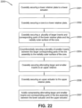
- a method 2200 for partially curing the tire assembly 140 includes a first step 2201 such that the lower retainer plate 220 is secured coaxially to the lower actuator 210 ( FIGS. 1-2 ).
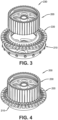
- a second step 2202 the core 230 is secured coaxially to the lower retainer plate 220 ( FIGS. 3-4 ).
- the larger inserts 240 and corresponding rubber sheets or first parts 145 are secured coaxially to the lower retainer plate 220 and the radially outer surface of the core 230 ( FIGS. 5-11 ).
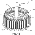
- a fourth step 2204 the smaller inserts 250 are secured circumferentially between the larger inserts/parts 240, 145 to the lower retainer plate 220 and the radially outer surface of the core 230 ( FIGS. 12-13 ).
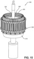
- the upper retainer plate 260 is secured coaxially to the alternating larger inserts 240 and smaller inserts 250 ( FIGS. 14-15 ).
- the upper actuator 270 is secured coaxially to the upper retainer plate 270 ( FIG. 16 ).
- the lower actuator 210 and upper actuator 270 are axially compressed such that the larger inserts 240 and smaller inserts 250 are radially and circumferentially secured and positioned against the core 230 ( FIG.
- the appropriately positioned plurality of rubber sheets or parts 145 of the tire assembly 140 are cured to each other by applying heat to the core 230 and larger inserts 240 ( FIG. 17 ).
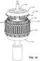
- the core 230 and the larger inserts 240 are cooled and the lower actuator 210 and upper actuator 270 are axially released and disengaged from the remaining structures 220, 230, 240, 250, 260 ( FIGS. 18-19 ).
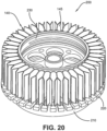
- the upper retainer plate 260, the larger inserts 240 and the smaller inserts 250 are removed from the core 230 ( FIG. 20 ).
- the lower actuator 210, the lower retainer plate 220, and core 230 are removed to reveal a cured single-piece structure made from the cured together parts 140 of the tire assembly 140 ( FIGS. 20-21 ).
- the larger inserts 240 preferably have internal channels 242 for contributing to the curing of the rubber sheets or parts 145 of the tire assembly 140.
- the channels 242 may have any suitable cross-section, such as circle, rectangle, square, pentagon, etc.
- the larger inserts 240 are preferably shaped to further assisting shaping of rubber sheets or the parts 145 ( FIG. 8 ).
- the channels 242 (upper and lower) are preferably heated to an appropriate curing temperature by any suitable means, such as steam, electricity, hot pressurized water, etc.
- the channels 242 are preferably secured at opposite ends by a first end wedge 244 and a second end wedge 246.
- the wedges 244, 246 preferably transfer a heating medium (e.g., hot liquid, steam, electricity, etc.) through first and second internal tubes 243, 245.
- a heating medium e.g., hot liquid, steam, electricity, etc.
- the larger inserts 240 preferably further include elongated, triangular first insulator members 256 at a radially outer part of the larger inserts.
- the smaller inserts 250 preferably further include elongated, rectangular second insulator members 252.
- first and second insulator members 252, 256 together enable radially outer flap members 147 of the rubber sheets or parts 145 to remain apart and uncured. These flap members 147 will thus be available for curing to other radially outer parts (not shown) of the tire assembly 140.
Landscapes
- Engineering & Computer Science (AREA)
- Mechanical Engineering (AREA)
- Physics & Mathematics (AREA)
- Health & Medical Sciences (AREA)
- Oral & Maxillofacial Surgery (AREA)
- Thermal Sciences (AREA)
- Tires In General (AREA)
- Moulds For Moulding Plastics Or The Like (AREA)
- Tyre Moulding (AREA)
- Heating, Cooling, Or Curing Plastics Or The Like In General (AREA)
Claims (15)
- Système destiné à la vulcanisation d'une portion d'un assemblage de bandage, qui comprend :un arbre de positionnement axial (205) ;un premier actionneur (210) disposé par glissement sur l'arbre de positionnement axial (205) ;une première plaque de retenue (220) disposée en position adjacente au premier actionneur (210) sur l'arbre de positionnement axial (205) ;une partie centrale (230) sur l'arbre de positionnement axial (205) ;un certain nombre de premiers inserts (240), dont chacun vient s'engrener dans la direction axiale et dans la direction radiale dans la surface externe de la partie centrale (230), des premières extrémités (244) des premiers inserts (240) venant s'engrener dans la direction axiale dans la première plaque de retenue (220) ;un certain nombre de deuxièmes inserts (250), dont chacun vient s'engrener dans la direction axiale et dans la direction radiale dans la surface externe de la partie centrale (230), des premières extrémités (244) des deuxièmes inserts (240) venant s'engrener dans la direction axiale dans la première plaque de retenue (220), chaque deuxième insert étant disposé dans la direction circonférentielle entre deux desdits plusieurs premiers inserts (240) ;une deuxième plaque de retenue (260) qui fixe des deuxièmes parties opposées (246) des premiers inserts (240) et des deuxièmes parties opposées des deuxièmes inserts (250) à l'arbre de positionnement axial (205) ; etun deuxième actionneur (270) disposé par glissement sur l'arbre de positionnement axial (205).
- Système tel que représenté dans la revendication 1, dans lequel le premier actionneur (210) et le deuxième actionneur (270) sont configurés pour comprimer de manière réciproque les premiers inserts (240) et des parties correspondantes de l'assemblage de bandage ; et/ou dans lequel la première plaque de retenue (220) et la deuxième plaque de retenue (260) fixent les premiers inserts (240) à la partie centrale (230).
- Système tel que représenté dans la revendication 1 ou 2, dans lequel la première plaque de retenue (220) et la deuxième plaque de retenue (260) sont configurées pour orienter un certain nombre de feuilles en caoutchouc (145) de l'assemblage de bandage par rapport à la partie centrale (230).
- Système tel que représenté dans au moins une des revendications précédentes, dans lequel les premiers inserts (240) possèdent des canaux internes (242) destinés à apporter leur contribution à la vulcanisation de parties de l'assemblage de bandage.
- Système tel que représenté dans au moins une des revendications précédentes, dans lequel les premiers inserts (240) sont configurés pour faciliter la configuration de parties de l'assemblage de bandage.
- Système tel que représenté dans au moins une des revendications précédentes, dans lequel des canaux internes (242) des premiers inserts (240) peuvent être chauffés, de préférence par l'intermédiaire d'un liquide chaud, par l'intermédiaire d'une vapeur ou par l'intermédiaire de l'électricité jusqu'à une température de vulcanisation appropriée pour l'assemblage de bandage.
- Procédé destiné à la vulcanisation d'une portion d'un assemblage de bandage, le procédé comprenant les étapes dans lesquelles :on fixe, en position coaxiale, une première plaque de retenue ou plaque de retenue inférieure (220) à un premier actionneur ou actionneur inférieur (210) ;on fixe, en position coaxiale, une partie centrale (230) à la première plaque de retenue ou plaque de retenue inférieure (220) ;on fixe, en position coaxiale, un certain nombre d'inserts plus grands (240) et de parties correspondantes de l'assemblage de bandage à la première plaque de retenue ou plaque de retenue inférieure (220) et à la surface externe, dans la direction axiale, de la partie centrale (230) ;on fixe, dans la direction circonférentielle, un certain nombre d'inserts plus petits (250) entre les inserts plus grands (240) et les parties correspondantes de l'assemblage de bandage à la surface externe, dans la direction radiale, de la partie centrale (230) ;on fixe, en position coaxiale, les inserts plus grands et les inserts plus petits qui alternent (240, 250) à une deuxième plaque de retenue ou plaque de retenue supérieure (260) ; eton fixe, en position coaxiale, un deuxième actionneur ou actionneur supérieur (270) à la deuxième plaque de retenue ou plaque de retenue supérieure (260) ; caractérisé parle fait de comprimer, dans la direction axiale, les inserts plus grands et les inserts plus petits qui alternent (240, 250) et des parties correspondantes de l'assemblage de bandage entre le premier actionneur ou actionneur inférieur (210) et le deuxième actionneur ou actionneur supérieur (270).
- Procédé tel que représenté à la revendication 7, qui englobe l'étape dans laquelle on chauffe des canaux internes (242) des inserts plus grands (240), de préférence par l'intermédiaire d'un liquide chaud.
- Procédé tel que représenté à la revendication 7 ou 8, qui englobe l'étape dans laquelle on fixe, en position coaxiale, la deuxième plaque de retenue ou plaque de retenue supérieure (260) aux inserts plus grands et aux inserts plus petits qui alternent (240, 250).
- Procédé tel que représenté dans au moins une des revendications 7 à 9, qui englobe l'étape dans laquelle on fixe dans la direction radiale et dans la direction circonférentielle les inserts plus grands (240) et les inserts plus petits (250) à la partie centrale (230).
- Procédé tel que représenté dans au moins une des revendications 7 à 10, qui englobe l'étape dans laquelle on positionne d'une manière appropriée les parties correspondantes de l'assemblage de bandage les unes par rapport aux autres.
- Procédé tel que représenté dans au moins une des revendications 7 à 10, qui englobe l'étape dans laquelle on applique de la chaleur sur la partie centrale (230) et sur les inserts plus grands (240).
- Procédé tel que représenté dans au moins une des revendications 7 à 11, qui englobe l'étape dans laquelle on refroidit la partie centrale (230) et les inserts plus grands (240).
- Procédé tel que représenté dans au moins une des revendications 7 à 13, qui englobe l'étape dans laquelle on procède au dégagement, dans la direction axiale, du deuxième actionneur ou actionneur supérieur (270) et du premier actionneur ou actionneur inférieur (210).
- Procédé tel que représenté dans au moins une des revendications 7 à 14, qui englobe l'étape dans laquelle on procède au découplage du deuxième actionneur ou actionneur supérieur (270) et du premier actionneur ou actionneur inférieur (210) par rapport à l'arbre de positionnement axial (250), et de manière facultative qui englobe en outre l'étape dans laquelle on révèle une structure vulcanisée en une seule pièce réalisée à partir de pièces de l'assemblage de bandages qui ont été assemblées par vulcanisation.
Applications Claiming Priority (1)
| Application Number | Priority Date | Filing Date | Title |
|---|---|---|---|
| US17/111,741 US11806960B2 (en) | 2020-12-04 | 2020-12-04 | System for manufacturing a support structure |
Publications (2)
| Publication Number | Publication Date |
|---|---|
| EP4008540A1 EP4008540A1 (fr) | 2022-06-08 |
| EP4008540B1 true EP4008540B1 (fr) | 2023-11-01 |
Family
ID=78819378
Family Applications (1)
| Application Number | Title | Priority Date | Filing Date |
|---|---|---|---|
| EP21211074.6A Active EP4008540B1 (fr) | 2020-12-04 | 2021-11-29 | Système et procédé de fabrication d'une structure de support |
Country Status (5)
| Country | Link |
|---|---|
| US (1) | US11806960B2 (fr) |
| EP (1) | EP4008540B1 (fr) |
| JP (1) | JP2022089812A (fr) |
| KR (1) | KR102564296B1 (fr) |
| CN (1) | CN114603895B (fr) |
Family Cites Families (35)
| Publication number | Priority date | Publication date | Assignee | Title |
|---|---|---|---|---|
| US482175A (en) | 1892-09-06 | George hollafolla | ||
| US479255A (en) | 1892-07-19 | boyd dunlop | ||
| US1002003A (en) | 1910-07-23 | 1911-08-29 | Christian J Simonson | Steel tire. |
| US1233722A (en) | 1917-01-03 | 1917-07-17 | Frederick Kemppel | Resilient wheel. |
| US1389285A (en) | 1920-03-29 | 1921-08-30 | August W Althoff | Vehicle-wheel |
| US1451517A (en) | 1922-02-27 | 1923-04-10 | William H Smith | Spring wheel |
| US1930764A (en) | 1931-11-05 | 1933-10-17 | Wingfoot Corp | Pneumatic tire and method of making same |
| US3493027A (en) | 1966-05-20 | 1970-02-03 | Nasa | Deformable vehicle wheel |
| US4226273A (en) | 1978-06-30 | 1980-10-07 | The Goodyear Tire & Rubber Company | Nonpneumatic tire and rim assembly |
| US4235270A (en) | 1978-06-30 | 1980-11-25 | The Goodyear Tire & Rubber Company | Tire with supporting and cushioning walls |
| US4257994A (en) | 1980-02-11 | 1981-03-24 | Teledyne Industries, Inc. | Method and apparatus for injection molding solid steel-banded press-on industrial rubber tires |
| US4602823A (en) | 1981-08-18 | 1986-07-29 | Berg Charles A | Portable collapsible wheels |
| CA2043082A1 (fr) | 1991-02-27 | 1992-08-28 | James Edward Duddey | Pneu de secours sans chambre |
| US5800643A (en) | 1996-04-26 | 1998-09-01 | Inner Tire Corporation | Pneumatic inner tire |
| US6260598B1 (en) | 1997-07-11 | 2001-07-17 | Sumitomo Rubber Industries, Ltd. | Pneumatic tire with looped tread-sidewall reinforcement |
| US6113833A (en) * | 1997-07-22 | 2000-09-05 | Bridgestone Corporation | Segmented toroidal core for manufacturing pneumatic tires |
| US6769468B2 (en) * | 2001-09-21 | 2004-08-03 | The Goodyear Tire & Rubber Company | Tire building drum having expandable center section and independently expandable bead lock assemblies in the end sections |
| US20040069385A1 (en) | 2002-07-01 | 2004-04-15 | Sean Timoney | Wheel |
| US7878600B2 (en) | 2007-06-05 | 2011-02-01 | Stellana U.S. Inc. | Mechanical fastener for polyurethane wheels |
| WO2009005945A1 (fr) | 2007-06-29 | 2009-01-08 | Societe De Technologie Michelin | Bande de cisaillement élastique à éléments cylindriques |
| US8061398B2 (en) * | 2008-02-25 | 2011-11-22 | Chemtura Corporation | Non-pneumatic tire having angled tread groove wall |
| FR2928865B1 (fr) | 2008-03-19 | 2010-03-19 | Michelin Soc Tech | Roue elastique non pneumatique |
| US9180732B2 (en) | 2009-08-28 | 2015-11-10 | Compagnie Generale Des Etablissements Michelin | Non-pneumatic wheel assembly with removable hub |
| US9149994B2 (en) | 2012-12-12 | 2015-10-06 | Caterpillar Inc. | Systems for molding non-pneumatic tires |
| US20150210025A1 (en) | 2014-01-24 | 2015-07-30 | Caterpillar Inc. | System for molding non-pneumatic tires |
| US10486462B2 (en) * | 2014-06-24 | 2019-11-26 | Bridgestone Corporation | Non-pneumatic tire |
| US10207544B2 (en) | 2016-11-15 | 2019-02-19 | The Goodyear Tire & Rubber Company | Wheel for a support structure |
| US10384409B2 (en) | 2016-11-15 | 2019-08-20 | The Goodyear Tire & Rubber Company | Method of manufacturing a non-pneumatic support structure |
| US12138971B2 (en) | 2017-04-27 | 2024-11-12 | Bridgestone Americas Tire Operations, Llc | Tire with spoke loops |
| US10471773B2 (en) * | 2017-06-07 | 2019-11-12 | The Goodyear Tire & Rubber Company | Method of manufacturing a non-pneumatic support structure |
| KR102005417B1 (ko) | 2017-09-11 | 2019-07-30 | 금호타이어 주식회사 | 비공기입 타이어용 림 및 이를 포함하는 휠 |
| US10406852B2 (en) | 2017-10-27 | 2019-09-10 | The Goodyear Tire & Rubber Company | Non-pneumatic support structure |
| CN111356581B (zh) * | 2017-11-21 | 2022-07-19 | 米其林集团总公司 | 形成非充气轮胎胎体的方法和设备 |
| US10457094B2 (en) | 2017-12-11 | 2019-10-29 | The Goodyear Tire & Rubber Company | Wheel for a support structure |
| US10603956B2 (en) | 2018-03-28 | 2020-03-31 | The Goodyear Tire & Rubber Company | Wheel for a support structure |
-
2020
- 2020-12-04 US US17/111,741 patent/US11806960B2/en active Active
-
2021
- 2021-11-25 KR KR1020210163962A patent/KR102564296B1/ko active Active
- 2021-11-29 EP EP21211074.6A patent/EP4008540B1/fr active Active
- 2021-12-03 CN CN202111465961.6A patent/CN114603895B/zh active Active
- 2021-12-06 JP JP2021197656A patent/JP2022089812A/ja active Pending
Also Published As
| Publication number | Publication date |
|---|---|
| KR20220079446A (ko) | 2022-06-13 |
| US20220176664A1 (en) | 2022-06-09 |
| JP2022089812A (ja) | 2022-06-16 |
| US11806960B2 (en) | 2023-11-07 |
| CN114603895B (zh) | 2024-11-05 |
| CN114603895A (zh) | 2022-06-10 |
| KR102564296B1 (ko) | 2023-08-04 |
| BR102021023627A2 (pt) | 2022-06-07 |
| EP4008540A1 (fr) | 2022-06-08 |
Similar Documents
| Publication | Publication Date | Title |
|---|---|---|
| US11020918B2 (en) | Method of manufacturing a non-pneumatic support structure | |
| EP3321098A1 (fr) | Structure de support non pneumatique | |
| EP3330098A1 (fr) | Ensemble roue pour une structure de support et système permettant de supporter une charge | |
| US10603956B2 (en) | Wheel for a support structure | |
| US11001021B2 (en) | Method of manufacturing a non-pneumatic support structure | |
| EP3599107B1 (fr) | Roue pour une structure de support | |
| EP4008539B1 (fr) | Système et procédé de fabrication d'une structure de support | |
| EP4008563B1 (fr) | Ensemble pneu/roue et procédé de support d'un véhicule | |
| EP4008540A1 (fr) | Système et procédé de fabrication d'une structure de support | |
| EP3812168B1 (fr) | Structure et procédé de support non pneumatique modulaire | |
| EP3822092B1 (fr) | Ensemble roue pour une structure de support | |
| EP4112286A1 (fr) | Système et procédé de fabrication d'une structure de support | |
| US12202219B2 (en) | System for manufacturing a support structure | |
| EP4197807B1 (fr) | Ensemble pneu/jante pour structure de support | |
| BR102021023627B1 (pt) | Sistema para curar uma porção de uma montagem de pneu |
Legal Events
| Date | Code | Title | Description |
|---|---|---|---|
| PUAI | Public reference made under article 153(3) epc to a published international application that has entered the european phase |
Free format text: ORIGINAL CODE: 0009012 |
|
| STAA | Information on the status of an ep patent application or granted ep patent |
Free format text: STATUS: THE APPLICATION HAS BEEN PUBLISHED |
|
| AK | Designated contracting states |
Kind code of ref document: A1 Designated state(s): AL AT BE BG CH CY CZ DE DK EE ES FI FR GB GR HR HU IE IS IT LI LT LU LV MC MK MT NL NO PL PT RO RS SE SI SK SM TR |
|
| RAP3 | Party data changed (applicant data changed or rights of an application transferred) |
Owner name: THE GOODYEAR TIRE & RUBBER COMPANY |
|
| STAA | Information on the status of an ep patent application or granted ep patent |
Free format text: STATUS: REQUEST FOR EXAMINATION WAS MADE |
|
| 17P | Request for examination filed |
Effective date: 20221208 |
|
| RBV | Designated contracting states (corrected) |
Designated state(s): AL AT BE BG CH CY CZ DE DK EE ES FI FR GB GR HR HU IE IS IT LI LT LU LV MC MK MT NL NO PL PT RO RS SE SI SK SM TR |
|
| GRAP | Despatch of communication of intention to grant a patent |
Free format text: ORIGINAL CODE: EPIDOSNIGR1 |
|
| STAA | Information on the status of an ep patent application or granted ep patent |
Free format text: STATUS: GRANT OF PATENT IS INTENDED |
|
| GRAJ | Information related to disapproval of communication of intention to grant by the applicant or resumption of examination proceedings by the epo deleted |
Free format text: ORIGINAL CODE: EPIDOSDIGR1 |
|
| STAA | Information on the status of an ep patent application or granted ep patent |
Free format text: STATUS: REQUEST FOR EXAMINATION WAS MADE |
|
| INTG | Intention to grant announced |
Effective date: 20230404 |
|
| INTC | Intention to grant announced (deleted) | ||
| GRAP | Despatch of communication of intention to grant a patent |
Free format text: ORIGINAL CODE: EPIDOSNIGR1 |
|
| STAA | Information on the status of an ep patent application or granted ep patent |
Free format text: STATUS: GRANT OF PATENT IS INTENDED |
|
| INTG | Intention to grant announced |
Effective date: 20230526 |
|
| GRAS | Grant fee paid |
Free format text: ORIGINAL CODE: EPIDOSNIGR3 |
|
| GRAA | (expected) grant |
Free format text: ORIGINAL CODE: 0009210 |
|
| STAA | Information on the status of an ep patent application or granted ep patent |
Free format text: STATUS: THE PATENT HAS BEEN GRANTED |
|
| AK | Designated contracting states |
Kind code of ref document: B1 Designated state(s): AL AT BE BG CH CY CZ DE DK EE ES FI FR GB GR HR HU IE IS IT LI LT LU LV MC MK MT NL NO PL PT RO RS SE SI SK SM TR |
|
| REG | Reference to a national code |
Ref country code: GB Ref legal event code: FG4D |
|
| REG | Reference to a national code |
Ref country code: CH Ref legal event code: EP |
|
| REG | Reference to a national code |
Ref country code: IE Ref legal event code: FG4D |
|
| REG | Reference to a national code |
Ref country code: DE Ref legal event code: R096 Ref document number: 602021006409 Country of ref document: DE |
|
| REG | Reference to a national code |
Ref country code: LT Ref legal event code: MG9D |
|
| REG | Reference to a national code |
Ref country code: NL Ref legal event code: MP Effective date: 20231101 |
|
| PG25 | Lapsed in a contracting state [announced via postgrant information from national office to epo] |
Ref country code: GR Free format text: LAPSE BECAUSE OF FAILURE TO SUBMIT A TRANSLATION OF THE DESCRIPTION OR TO PAY THE FEE WITHIN THE PRESCRIBED TIME-LIMIT Effective date: 20240202 |
|
| PG25 | Lapsed in a contracting state [announced via postgrant information from national office to epo] |
Ref country code: IS Free format text: LAPSE BECAUSE OF FAILURE TO SUBMIT A TRANSLATION OF THE DESCRIPTION OR TO PAY THE FEE WITHIN THE PRESCRIBED TIME-LIMIT Effective date: 20240301 |
|
| PG25 | Lapsed in a contracting state [announced via postgrant information from national office to epo] |
Ref country code: LT Free format text: LAPSE BECAUSE OF FAILURE TO SUBMIT A TRANSLATION OF THE DESCRIPTION OR TO PAY THE FEE WITHIN THE PRESCRIBED TIME-LIMIT Effective date: 20231101 |
|
| REG | Reference to a national code |
Ref country code: AT Ref legal event code: MK05 Ref document number: 1626750 Country of ref document: AT Kind code of ref document: T Effective date: 20231101 |
|
| PG25 | Lapsed in a contracting state [announced via postgrant information from national office to epo] |
Ref country code: NL Free format text: LAPSE BECAUSE OF FAILURE TO SUBMIT A TRANSLATION OF THE DESCRIPTION OR TO PAY THE FEE WITHIN THE PRESCRIBED TIME-LIMIT Effective date: 20231101 |
|
| PG25 | Lapsed in a contracting state [announced via postgrant information from national office to epo] |
Ref country code: AT Free format text: LAPSE BECAUSE OF FAILURE TO SUBMIT A TRANSLATION OF THE DESCRIPTION OR TO PAY THE FEE WITHIN THE PRESCRIBED TIME-LIMIT Effective date: 20231101 |
|
| PG25 | Lapsed in a contracting state [announced via postgrant information from national office to epo] |
Ref country code: ES Free format text: LAPSE BECAUSE OF FAILURE TO SUBMIT A TRANSLATION OF THE DESCRIPTION OR TO PAY THE FEE WITHIN THE PRESCRIBED TIME-LIMIT Effective date: 20231101 |
|
| PG25 | Lapsed in a contracting state [announced via postgrant information from national office to epo] |
Ref country code: NL Free format text: LAPSE BECAUSE OF FAILURE TO SUBMIT A TRANSLATION OF THE DESCRIPTION OR TO PAY THE FEE WITHIN THE PRESCRIBED TIME-LIMIT Effective date: 20231101 Ref country code: LT Free format text: LAPSE BECAUSE OF FAILURE TO SUBMIT A TRANSLATION OF THE DESCRIPTION OR TO PAY THE FEE WITHIN THE PRESCRIBED TIME-LIMIT Effective date: 20231101 Ref country code: IS Free format text: LAPSE BECAUSE OF FAILURE TO SUBMIT A TRANSLATION OF THE DESCRIPTION OR TO PAY THE FEE WITHIN THE PRESCRIBED TIME-LIMIT Effective date: 20240301 Ref country code: GR Free format text: LAPSE BECAUSE OF FAILURE TO SUBMIT A TRANSLATION OF THE DESCRIPTION OR TO PAY THE FEE WITHIN THE PRESCRIBED TIME-LIMIT Effective date: 20240202 Ref country code: ES Free format text: LAPSE BECAUSE OF FAILURE TO SUBMIT A TRANSLATION OF THE DESCRIPTION OR TO PAY THE FEE WITHIN THE PRESCRIBED TIME-LIMIT Effective date: 20231101 Ref country code: BG Free format text: LAPSE BECAUSE OF FAILURE TO SUBMIT A TRANSLATION OF THE DESCRIPTION OR TO PAY THE FEE WITHIN THE PRESCRIBED TIME-LIMIT Effective date: 20240201 Ref country code: AT Free format text: LAPSE BECAUSE OF FAILURE TO SUBMIT A TRANSLATION OF THE DESCRIPTION OR TO PAY THE FEE WITHIN THE PRESCRIBED TIME-LIMIT Effective date: 20231101 Ref country code: PT Free format text: LAPSE BECAUSE OF FAILURE TO SUBMIT A TRANSLATION OF THE DESCRIPTION OR TO PAY THE FEE WITHIN THE PRESCRIBED TIME-LIMIT Effective date: 20240301 |
|
| PG25 | Lapsed in a contracting state [announced via postgrant information from national office to epo] |
Ref country code: SE Free format text: LAPSE BECAUSE OF FAILURE TO SUBMIT A TRANSLATION OF THE DESCRIPTION OR TO PAY THE FEE WITHIN THE PRESCRIBED TIME-LIMIT Effective date: 20231101 Ref country code: RS Free format text: LAPSE BECAUSE OF FAILURE TO SUBMIT A TRANSLATION OF THE DESCRIPTION OR TO PAY THE FEE WITHIN THE PRESCRIBED TIME-LIMIT Effective date: 20231101 Ref country code: PL Free format text: LAPSE BECAUSE OF FAILURE TO SUBMIT A TRANSLATION OF THE DESCRIPTION OR TO PAY THE FEE WITHIN THE PRESCRIBED TIME-LIMIT Effective date: 20231101 Ref country code: NO Free format text: LAPSE BECAUSE OF FAILURE TO SUBMIT A TRANSLATION OF THE DESCRIPTION OR TO PAY THE FEE WITHIN THE PRESCRIBED TIME-LIMIT Effective date: 20240201 Ref country code: LV Free format text: LAPSE BECAUSE OF FAILURE TO SUBMIT A TRANSLATION OF THE DESCRIPTION OR TO PAY THE FEE WITHIN THE PRESCRIBED TIME-LIMIT Effective date: 20231101 Ref country code: HR Free format text: LAPSE BECAUSE OF FAILURE TO SUBMIT A TRANSLATION OF THE DESCRIPTION OR TO PAY THE FEE WITHIN THE PRESCRIBED TIME-LIMIT Effective date: 20231101 |
|
| PG25 | Lapsed in a contracting state [announced via postgrant information from national office to epo] |
Ref country code: DK Free format text: LAPSE BECAUSE OF FAILURE TO SUBMIT A TRANSLATION OF THE DESCRIPTION OR TO PAY THE FEE WITHIN THE PRESCRIBED TIME-LIMIT Effective date: 20231101 |
|
| PG25 | Lapsed in a contracting state [announced via postgrant information from national office to epo] |
Ref country code: LU Free format text: LAPSE BECAUSE OF NON-PAYMENT OF DUE FEES Effective date: 20231129 |
|
| PG25 | Lapsed in a contracting state [announced via postgrant information from national office to epo] |
Ref country code: CZ Free format text: LAPSE BECAUSE OF FAILURE TO SUBMIT A TRANSLATION OF THE DESCRIPTION OR TO PAY THE FEE WITHIN THE PRESCRIBED TIME-LIMIT Effective date: 20231101 |
|
| PG25 | Lapsed in a contracting state [announced via postgrant information from national office to epo] |
Ref country code: SK Free format text: LAPSE BECAUSE OF FAILURE TO SUBMIT A TRANSLATION OF THE DESCRIPTION OR TO PAY THE FEE WITHIN THE PRESCRIBED TIME-LIMIT Effective date: 20231101 |
|
| PG25 | Lapsed in a contracting state [announced via postgrant information from national office to epo] |
Ref country code: SM Free format text: LAPSE BECAUSE OF FAILURE TO SUBMIT A TRANSLATION OF THE DESCRIPTION OR TO PAY THE FEE WITHIN THE PRESCRIBED TIME-LIMIT Effective date: 20231101 Ref country code: SK Free format text: LAPSE BECAUSE OF FAILURE TO SUBMIT A TRANSLATION OF THE DESCRIPTION OR TO PAY THE FEE WITHIN THE PRESCRIBED TIME-LIMIT Effective date: 20231101 Ref country code: LU Free format text: LAPSE BECAUSE OF NON-PAYMENT OF DUE FEES Effective date: 20231129 Ref country code: IT Free format text: LAPSE BECAUSE OF FAILURE TO SUBMIT A TRANSLATION OF THE DESCRIPTION OR TO PAY THE FEE WITHIN THE PRESCRIBED TIME-LIMIT Effective date: 20231101 Ref country code: EE Free format text: LAPSE BECAUSE OF FAILURE TO SUBMIT A TRANSLATION OF THE DESCRIPTION OR TO PAY THE FEE WITHIN THE PRESCRIBED TIME-LIMIT Effective date: 20231101 Ref country code: DK Free format text: LAPSE BECAUSE OF FAILURE TO SUBMIT A TRANSLATION OF THE DESCRIPTION OR TO PAY THE FEE WITHIN THE PRESCRIBED TIME-LIMIT Effective date: 20231101 Ref country code: CZ Free format text: LAPSE BECAUSE OF FAILURE TO SUBMIT A TRANSLATION OF THE DESCRIPTION OR TO PAY THE FEE WITHIN THE PRESCRIBED TIME-LIMIT Effective date: 20231101 |
|
| REG | Reference to a national code |
Ref country code: BE Ref legal event code: MM Effective date: 20231130 |
|
| REG | Reference to a national code |
Ref country code: DE Ref legal event code: R097 Ref document number: 602021006409 Country of ref document: DE |
|
| PG25 | Lapsed in a contracting state [announced via postgrant information from national office to epo] |
Ref country code: MC Free format text: LAPSE BECAUSE OF FAILURE TO SUBMIT A TRANSLATION OF THE DESCRIPTION OR TO PAY THE FEE WITHIN THE PRESCRIBED TIME-LIMIT Effective date: 20231101 |
|
| PG25 | Lapsed in a contracting state [announced via postgrant information from national office to epo] |
Ref country code: MC Free format text: LAPSE BECAUSE OF FAILURE TO SUBMIT A TRANSLATION OF THE DESCRIPTION OR TO PAY THE FEE WITHIN THE PRESCRIBED TIME-LIMIT Effective date: 20231101 |
|
| PLBE | No opposition filed within time limit |
Free format text: ORIGINAL CODE: 0009261 |
|
| STAA | Information on the status of an ep patent application or granted ep patent |
Free format text: STATUS: NO OPPOSITION FILED WITHIN TIME LIMIT |
|
| REG | Reference to a national code |
Ref country code: IE Ref legal event code: MM4A |
|
| 26N | No opposition filed |
Effective date: 20240802 |
|
| PG25 | Lapsed in a contracting state [announced via postgrant information from national office to epo] |
Ref country code: IE Free format text: LAPSE BECAUSE OF NON-PAYMENT OF DUE FEES Effective date: 20231129 |
|
| PG25 | Lapsed in a contracting state [announced via postgrant information from national office to epo] |
Ref country code: BE Free format text: LAPSE BECAUSE OF NON-PAYMENT OF DUE FEES Effective date: 20231130 |
|
| PG25 | Lapsed in a contracting state [announced via postgrant information from national office to epo] |
Ref country code: SI Free format text: LAPSE BECAUSE OF FAILURE TO SUBMIT A TRANSLATION OF THE DESCRIPTION OR TO PAY THE FEE WITHIN THE PRESCRIBED TIME-LIMIT Effective date: 20231101 |
|
| PG25 | Lapsed in a contracting state [announced via postgrant information from national office to epo] |
Ref country code: SI Free format text: LAPSE BECAUSE OF FAILURE TO SUBMIT A TRANSLATION OF THE DESCRIPTION OR TO PAY THE FEE WITHIN THE PRESCRIBED TIME-LIMIT Effective date: 20231101 Ref country code: IE Free format text: LAPSE BECAUSE OF NON-PAYMENT OF DUE FEES Effective date: 20231129 Ref country code: BE Free format text: LAPSE BECAUSE OF NON-PAYMENT OF DUE FEES Effective date: 20231130 |
|
| PG25 | Lapsed in a contracting state [announced via postgrant information from national office to epo] |
Ref country code: RO Free format text: LAPSE BECAUSE OF FAILURE TO SUBMIT A TRANSLATION OF THE DESCRIPTION OR TO PAY THE FEE WITHIN THE PRESCRIBED TIME-LIMIT Effective date: 20231101 |
|
| REG | Reference to a national code |
Ref country code: CH Ref legal event code: PL |
|
| PG25 | Lapsed in a contracting state [announced via postgrant information from national office to epo] |
Ref country code: FI Free format text: LAPSE BECAUSE OF FAILURE TO SUBMIT A TRANSLATION OF THE DESCRIPTION OR TO PAY THE FEE WITHIN THE PRESCRIBED TIME-LIMIT Effective date: 20231101 |
|
| REG | Reference to a national code |
Ref country code: CH Ref legal event code: PL |
|
| PG25 | Lapsed in a contracting state [announced via postgrant information from national office to epo] |
Ref country code: CH Free format text: LAPSE BECAUSE OF NON-PAYMENT OF DUE FEES Effective date: 20241130 |
|
| PG25 | Lapsed in a contracting state [announced via postgrant information from national office to epo] |
Ref country code: CY Free format text: LAPSE BECAUSE OF FAILURE TO SUBMIT A TRANSLATION OF THE DESCRIPTION OR TO PAY THE FEE WITHIN THE PRESCRIBED TIME-LIMIT; INVALID AB INITIO Effective date: 20211129 |
|
| PG25 | Lapsed in a contracting state [announced via postgrant information from national office to epo] |
Ref country code: TR Free format text: LAPSE BECAUSE OF FAILURE TO SUBMIT A TRANSLATION OF THE DESCRIPTION OR TO PAY THE FEE WITHIN THE PRESCRIBED TIME-LIMIT Effective date: 20231101 |
|
| PGFP | Annual fee paid to national office [announced via postgrant information from national office to epo] |
Ref country code: DE Payment date: 20251126 Year of fee payment: 5 |
|
| PGFP | Annual fee paid to national office [announced via postgrant information from national office to epo] |
Ref country code: GB Payment date: 20251121 Year of fee payment: 5 |
|
| PGFP | Annual fee paid to national office [announced via postgrant information from national office to epo] |
Ref country code: FR Payment date: 20251120 Year of fee payment: 5 |
|
| PG25 | Lapsed in a contracting state [announced via postgrant information from national office to epo] |
Ref country code: HU Free format text: LAPSE BECAUSE OF FAILURE TO SUBMIT A TRANSLATION OF THE DESCRIPTION OR TO PAY THE FEE WITHIN THE PRESCRIBED TIME-LIMIT; INVALID AB INITIO Effective date: 20211129 |