EP4008570A1 - Attelage de remorque doté d'un col de la boule d'attelage et boule d'attelage, ainsi que leur procédé de fabrication - Google Patents
Attelage de remorque doté d'un col de la boule d'attelage et boule d'attelage, ainsi que leur procédé de fabrication Download PDFInfo
- Publication number
- EP4008570A1 EP4008570A1 EP22151172.8A EP22151172A EP4008570A1 EP 4008570 A1 EP4008570 A1 EP 4008570A1 EP 22151172 A EP22151172 A EP 22151172A EP 4008570 A1 EP4008570 A1 EP 4008570A1
- Authority
- EP
- European Patent Office
- Prior art keywords
- ball
- coupling
- neck
- transition
- ball neck
- Prior art date
- Legal status (The legal status is an assumption and is not a legal conclusion. Google has not performed a legal analysis and makes no representation as to the accuracy of the status listed.)
- Granted
Links
Images


Classifications
-
- B—PERFORMING OPERATIONS; TRANSPORTING
- B60—VEHICLES IN GENERAL
- B60D—VEHICLE CONNECTIONS
- B60D1/00—Traction couplings; Hitches; Draw-gear; Towing devices
- B60D1/01—Traction couplings or hitches characterised by their type
- B60D1/06—Ball-and-socket hitches
- B60D1/065—Ball-and-socket hitches characterised by the hitch mechanism
-
- B—PERFORMING OPERATIONS; TRANSPORTING
- B60—VEHICLES IN GENERAL
- B60D—VEHICLE CONNECTIONS
- B60D1/00—Traction couplings; Hitches; Draw-gear; Towing devices
- B60D1/01—Traction couplings or hitches characterised by their type
- B60D1/06—Ball-and-socket hitches
-
- F—MECHANICAL ENGINEERING; LIGHTING; HEATING; WEAPONS; BLASTING
- F16—ENGINEERING ELEMENTS AND UNITS; GENERAL MEASURES FOR PRODUCING AND MAINTAINING EFFECTIVE FUNCTIONING OF MACHINES OR INSTALLATIONS; THERMAL INSULATION IN GENERAL
- F16C—SHAFTS; FLEXIBLE SHAFTS; ELEMENTS OR CRANKSHAFT MECHANISMS; ROTARY BODIES OTHER THAN GEARING ELEMENTS; BEARINGS
- F16C11/00—Pivots; Pivotal connections
- F16C11/04—Pivotal connections
- F16C11/06—Ball-joints; Other joints having more than one degree of angular freedom, i.e. universal joints
- F16C11/0685—Manufacture of ball-joints and parts thereof, e.g. assembly of ball-joints
- F16C11/069—Manufacture of ball-joints and parts thereof, e.g. assembly of ball-joints with at least one separate part to retain the ball member in the socket; Quick-release systems
-
- B—PERFORMING OPERATIONS; TRANSPORTING
- B60—VEHICLES IN GENERAL
- B60D—VEHICLE CONNECTIONS
- B60D1/00—Traction couplings; Hitches; Draw-gear; Towing devices
- B60D1/48—Traction couplings; Hitches; Draw-gear; Towing devices characterised by the mounting
- B60D1/52—Traction couplings; Hitches; Draw-gear; Towing devices characterised by the mounting removably mounted
-
- B—PERFORMING OPERATIONS; TRANSPORTING
- B60—VEHICLES IN GENERAL
- B60D—VEHICLE CONNECTIONS
- B60D1/00—Traction couplings; Hitches; Draw-gear; Towing devices
- B60D1/48—Traction couplings; Hitches; Draw-gear; Towing devices characterised by the mounting
- B60D1/54—Traction couplings; Hitches; Draw-gear; Towing devices characterised by the mounting collapsible or retractable when not in use, e.g. hide-away hitches
-
- B—PERFORMING OPERATIONS; TRANSPORTING
- B60—VEHICLES IN GENERAL
- B60R—VEHICLES, VEHICLE FITTINGS, OR VEHICLE PARTS, NOT OTHERWISE PROVIDED FOR
- B60R9/00—Supplementary fittings on vehicle exterior for carrying loads, e.g. luggage, sports gear or the like
- B60R9/06—Supplementary fittings on vehicle exterior for carrying loads, e.g. luggage, sports gear or the like at vehicle front or rear
-
- B—PERFORMING OPERATIONS; TRANSPORTING
- B62—LAND VEHICLES FOR TRAVELLING OTHERWISE THAN ON RAILS
- B62D—MOTOR VEHICLES; TRAILERS
- B62D25/00—Superstructure or monocoque structure sub-units; Parts or details thereof not otherwise provided for
- B62D25/20—Floors or bottom sub-units
- B62D25/209—Arrangements for the mounting of vehicle hitches
-
- B—PERFORMING OPERATIONS; TRANSPORTING
- B62—LAND VEHICLES FOR TRAVELLING OTHERWISE THAN ON RAILS
- B62D—MOTOR VEHICLES; TRAILERS
- B62D29/00—Superstructures, understructures, or sub-units thereof, characterised by the material thereof
- B62D29/001—Superstructures, understructures, or sub-units thereof, characterised by the material thereof characterised by combining metal and synthetic material
Definitions
- the invention relates to a trailer coupling for a motor vehicle, the trailer coupling having a coupling arm on whose free end area a ball neck is formed, on which a coupling ball for attaching a trailer or coupling a load carrier to the motor vehicle is arranged, the coupling ball being at its end separated from the
- the side facing away from the ball neck is spherical and has a ball segment plane on its side facing the ball neck, a throat section with a transition contour running concavely between the ball neck and the ball segment plane being arranged between the ball segment plane and a section of the ball neck which has a smaller outer circumference than the ball segment plane , which merges with a coupling ball transition area into an outer contour of the coupling ball, in particular in the spherical segment plane, and with a ball neck transition area into an outer surface of the ball neck. Furthermore, the invention relates to a method for producing such a trailer hitch.
- a typical ball rod or a ball rod neck according to the standard is designed according to ISO 1302 and ECE-R 55, for example.
- the coupling ball has a target diameter of about 50 mm, for example, and the ball neck has a diameter of 29 mm.
- the coupling ball is usually flattened at the top and has a lower ball segment level, which is designed as a circular ring surface.
- a groove usually extends between the annular surface and the cylindrical outer circumference of the ball neck. While the coupling ball itself and the ball neck are relatively high loads occur in the area of the throat section or at the transition from the coupling ball to the throat section or the ball neck to the throat section, high bending stresses that can lead to the coupling arm collapsing and breaking.
- the transition contour has a curved profile with a non-constant radius and/or has at least two different radii.
- the non-constant radius can thus comprise, for example, two or more radii that differ from one another, or the curved course can be formed by two or more radii that differ from one another.
- the radii preferably merge tangentially and/or uniformly into one another.
- the trailer hitch according to the invention is expediently suitable for ball-jointed mounting of a trailer ball hitch.
- a coupling socket or spherical receiving contour of the trailer ball coupling can be placed on the coupling ball in a manner known per se and is mounted there with a ball joint.
- a load carrier can also be placed on the coupling ball and braced with the trailer hitch.
- the free end area of the coupling arm namely the ball neck and the coupling ball, are expediently made or manufactured in one piece or from one piece.
- An arm body carrying the ball neck which will be discussed later, can also be in one piece with the ball neck and the coupling ball.
- the arm section it is also possible for the arm section to be formed by a first body and the ball neck and the coupling ball by a second body, which are connected to one another, for example screwed, welded, glued or the like.
- the ball neck and the coupling ball are expediently rotationally symmetrical. In particular, they are symmetrical about the same axis of rotation.
- a screw thread can be provided, which is arranged on the free end area or on the area of the ball neck facing away from the coupling ball.
- the area of the ball neck facing away from the coupling ball can also be a plug-in body for plugging in or plugging onto or onto a corresponding plug-in receptacle on the arm body.
- the arm body itself in turn, on which the ball neck and the coupling ball are arranged, can be rotationally symmetrical, but it does not have to be.
- reinforcements, reinforcement ribs, depressions, recesses or the like can be arranged or provided on the arm body.
- the coupling ball and the ball neck can be produced, for example, as part of a casting process.
- a reshaping of a blank, particularly in the area of the transition contour for the formation of the coupling ball and ball neck, is preferred.
- the method according to the invention for producing a trailer hitch for a motor vehicle having a coupling arm, on the free end of which a ball neck is formed, on which a coupling ball for attaching a trailer or coupling a load carrier to the motor vehicle is arranged, the coupling ball at its is spherical on the side facing away from the ball neck and has a ball segment plane on its side facing the ball neck, wherein between the ball segment plane and a section of the ball neck, which has a smaller outer circumference than the ball segment plane, there is a throat section with a transition contour that runs concavely between the ball neck and the ball segment plane is arranged, with a coupling ball transition area in an outer contour of the coupling ball, in particular in the ball segment plane, and with a ball neck transition area in an outer surface of the ball neck, sees a cutting processing and/or forming, in particular forging and/or rolling and/or profiling and/or rolling, of a blank to form the throat section in such a way that
- the coupling arm can be produced at least partially by longitudinally rolling or rolling a blank along its direction of longitudinal extension.
- the semi-finished blank, so to speak, can then be brought into its final shape by, for example, machining and/or by round rolling.
- the blank can only be processed in the above manner in the area of the ball neck and the coupling ball.
- a curved course with a non-constant radius is provided instead of a typically constant radius, namely a radius of the transition contour between the cylindrical ball neck and the underside of the coupling ball, ie the ball segment plane.
- a relatively gentle progression can be achieved between the ball neck on the one hand and/or the throat section and the coupling ball on the other hand.
- Hard or sharp transitions between the "groove" of the throat section and the coupling ball and/or the ball neck can be avoided.
- this allows the cross-sectional area of the throat portion to be larger, which increases the load capacity of the coupling arm.
- the method provides for hot forming, for example upsetting and/or forging.
- the roller processing, the profiling, the rolling or the like takes place while the blank is still at least warm, semi-warm, preferably hot.
- the non-constantly curved course of the transition contour can be used, for example, to avoid or significantly reduce local notch stresses at so-called geometric corners and/or notches.
- the transition contour is adapted to the load on the coupling arm.
- the transition contour has a structure that is suitable for the load and is adapted to the stress profile when the trailer hitch is used by a trailer or load carrier.
- the transition contour in the coupling ball transition area for example directly adjacent to the coupling ball, has a larger radius or several larger radii than in an intermediate section between the transition areas.
- the other transition area namely the ball neck transition area, for example directly adjacent to the ball neck or remote from it, expediently has at least a larger radius than an intermediate section of the transition contour between the transition areas. It is thus possible for the transition contour between the transition areas to have a relatively small radius, while in the transition areas to the coupling ball or to the coupling arm or its arm body it runs out gently with a large radius.
- the radii at points of the transition contour that are directly next to one another can differ from one another. But it is also possible that several points or a line segment or Contour section of the transition contour has a constant radius, while adjacent areas of the transition contour have one or more other radii.
- transition contour has a large number of different radii.
- transition contour is in the form of a spline contour or a polynomial curve.
- a spline or polynomial is a function piecewise composed of polynomials of at most an nth degree. Connection points or nodes where two polynomial pieces or polynomial sections meet, certain conditions must be met, for example that the spline or polynomial can be continuously differentiated (n-1) times.
- the transition contour can be continuously differentiated at least once at all points along its course.
- the transition contour it is also possible for the transition contour to be essentially continuously differentiable at least once.
- transition contour merges tangentially or without an angle into the spherical segment plane and/or the spherical neck.
- the transition contour thus transitions gently, so to speak, into the spherical segment plane or the spherical neck.
- a kink or angle would create a local notch stress that would result in a reduced load capacity of the coupling arm.
- the transition contour can only have a single curvature or a single direction of curvature. But it is also possible that the transition contour has at least two or more curved sections which have a curvature in opposite directions. It is possible, for example, for the transition contour to have at least one section running in an S-shape or a wavy section, or to run in an S-shape or wavy overall.
- the transition contour can, so to speak, have a continuous course and have the same curvatures. However, it is also possible for the transitional contour to have a narrowing between the transitional areas.
- the throat section can only have outer circumferences that are larger than its outer circumference of the ball neck. As a result, the adaptation between the ball neck, which has a smaller diameter, and the coupling ball can be implemented without further ado. However, it is also possible for the throat section to have at least one outer circumference which is smaller than its outer circumference of the ball neck. Consequently, the throat section can have a type of waist or constriction, for example.
- the ball neck can be designed as a continuous cylinder, in particular as a circular cylinder. However, it is also possible for the ball neck to have a waist. The waist is rounded, for example. Furthermore, it is advantageous if the transition contour extends to a minimum outer circumference, in particular a circular diameter of the ball neck. It is therefore also possible for the ball neck as such to have a smaller outer circumference or to have a smaller cross-sectional area in that area which adjoins the transition contour.
- the waist or a constriction of the ball neck is expediently designed in such a way that it moves within predetermined and/or standardized tolerances.
- a maximum diameter of the ball neck is defined as 29 mm, while the narrowing or constriction can be a maximum of 2 mm, so that the diameter of the narrowing or the diameter of the ball neck is minimal in the area of its smallest diameter is 27 mm.
- the ball neck has a diameter of about 28-29 mm, for example, while the smallest diameter, especially in the area of the waist, is only 27-28 mm.
- the ball neck is expediently arranged on an end area of an arm body, the other end area of which is designed and provided for connection to the motor vehicle.
- a holder is provided for connection to the motor vehicle, for example a retaining bracket, a bearing, a socket or the like.
- the coupling arm or arm body expediently has a bearing element for movably mounting on the holder or a plug-in contour for plugging into the holder. It is also possible for screw holes or similar other holding contours to be provided on the coupling arm or the arm body for attachment to the holder.
- the arm body has one or more curves or bends to conform to a body structure or bumper contour of the motor vehicle.
- the arm body is therefore that component or that section of the coupling arm which, so to speak, creates the connection between the ball neck and the motor vehicle.
- the arm body is expediently a solid component compared to the ball neck.
- the arm body and/or the ball neck and/or the coupling ball are made in one piece and/or from a common blank.
- the ball neck While it is advantageous for the ball neck to be annular in cross-section or cylindrical, it is possible for the arm body to be substantially non-annular in cross-section.
- the arm body has ribbing, support structures or the like that are not provided for in the ball neck.
- the arm body has a larger cross-sectional area than the ball neck immediately next to the ball neck.
- the carrying capacity of the arm body is expediently very high.
- the ball neck expediently has a smaller outer circumference, for example a smaller diameter, close to the throat section than in an area remote from the throat section.
- the ball neck can taper off in the direction of the throat section in the manner of a truncated cone or the like.
- the jacket surface of the ball neck immediately next to the throat section or the ball neck as a whole is expediently designed as the cylinder jacket of a circular cylinder.
- the ball neck is advantageously configured entirely or essentially as a circular cylinder.
- the spherical segment plane can be a purely geometric plane, i.e. it is not designed as a free-standing surface.
- an outer surface of the coupling arm can also be provided or formed in the spherical segment plane.
- an annular surface is provided in the ball segment plane, the outer diameter of which borders on the spherical ball surface of the coupling ball and the inner diameter or inner circumference of which borders on the coupling ball transition area or merges into the coupling ball transition area. Consequently, a circular ring surface is provided for reaching behind or under, for example, a load carrier.
- a flat surface is expediently provided in the spherical segment plane or the spherical segment plane is designed as a flat surface.
- the aforementioned annular surface is designed as a flat surface.
- the coupling ball transition region expediently has a depression which extends away from the ball neck behind the ball segment plane.
- the indentation is designed as a kind of undercut or undercut.
- the transition contour has an S-shaped profile, for example in the area of the rear grip or the depression.
- the above-mentioned curvatures or curves in opposite directions run, for example, in the spherical segment plane or around the spherical segment plane of the coupling ball.
- An undercut is, for example, a removal of a rotationally symmetrical inner edge with a specific shape and specified dimensions, which gives the tool used a free space during production.
- an S-shaped course or a course of the transition contour with oppositely directed curvatures may be provided close to the ball neck, in particular in the transition area to the ball neck.
- the coupling ball is expediently flattened in its area facing away from the ball neck.
- the coupling ball has a planar surface running parallel to the ball segment plane.
- the coupling ball can expediently be designed as a spherical segment ball, which has a flattened area, in particular a plane surface, on its area facing away from the ball neck and on its area facing the ball neck.
- the flat areas can be used, for example, as a positioning aid or support surfaces for a load carrier.
- the coupling ball and/or the ball neck and/or the throat section are expediently produced by forming.
- Forging, upsetting, rolling or profiling are particularly suitable as forming.
- the forming takes place expediently in the warm, in particular in the hot state of a blank for the production of the coupling arm.
- the production of the coupling arm is preferably such that the base material of the throat section has a microstructure with essentially or exclusively uninterrupted or intact fiber courses. Such an intact microstructure, so to speak, can be retained precisely by the mentioned hot forming, the rolling, in particular the stretching rolling or the like.
- the coupling arm is more resilient than known coupling arms, particularly in the area of the coupling ball and the throat section and ball neck below it.
- the plane of the spherical segment is expediently perpendicular to a longitudinal axis of the spherical neck.
- the ball neck and the coupling ball are preferably made of metal, in particular steel or aluminum.
- the coupling arm as a whole, at least in that section where it is connected to the ball neck and the coupling ball or is in one piece, consists of steel or aluminum.
- so-called structural steel high-strength materials, for example from the group of heat-treatable steels or precipitation-hardening ferritic-pearlitic steels or AFP steels, are preferred. Bainitic steels are also advantageous.
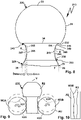
- a trailer coupling 10, 110, 210 is arranged on a motor vehicle 80, for example.
- a load carrier 90 or a trailer 190 (in figure 4 shown schematically) are coupled, so that, for example, a load, in particular bicycles F, or loads to be transported on a trailer 190, can be transported by the motor vehicle 80.
- Motor vehicle 80 is, for example, a motor vehicle with an internal combustion engine, an electric motor, or a hybrid engine. In any case, the loading capacity or transport capacity of the motor vehicle 80 can be increased by the load carrier 90 or a trailer 190 .
- the trailer hitch 10 comprises, for example, a carrier arrangement 11 which can be fastened to a body 81 of the motor vehicle 80 .
- the carrier arrangement 11 comprises, for example, a cross member and side members or longitudinal members that can be fastened to the body structure of the body 81, for example screwed.
- a holder 12 of the trailer hitch 10 is attached to the carrier arrangement 11 .
- the holder 12 carries a clutch arm 20 or holds a clutch arm 20.
- the clutch arm 20 is by means of a bearing 13 between a in the 1 illustrated use position G, in which the coupling arm 20 protrudes substantially in front of a bumper 83 of the motor vehicle 80, and a non-use position N adjustable, where it is hidden in particular behind the bumper 83 positioned on the motor vehicle 80.
- the coupling arm 20 can be locked using a locking device, for example using a form-fit locking mechanism or the like.
- the coupling arm 20 can be unlocked in order to be adjusted between the use position G and the non-use position N, to be pivoted, for example, or to be linearly displaced, or both. Consequently, the bearing 13 is, for example, a pivot bearing, sliding bearing or pivoting sliding bearing. But that is not what matters in the first place.
- the coupling arm 20 can also be held firmly on the holder 12, for example using a screw connection, or can be releasably connected to the holder 12 using a plug-in connection.
- a drive 17 is preferably provided, which can also be referred to as a swivel drive.
- the coupling arm 20 has an arm body 26 with an end region 21 which is intended for connection to the holder 12.
- the arm body 26 is firmly connected, in particular in one piece, to a bearing element 14, for example a bearing head.
- the bearing element 14 is pivotably and/or displaceably mounted on the holder 12, for example by means of a bearing bolt.
- a curved section 22 connects to the end region 21 .
- the curved section 22 serves, so to speak, so that the coupling arm 20 can protrude upwards from under the bumper 83 in the use position G.
- the curved section 22 is followed by a substantially straight arm section 23 which merges into a further curved section 24 .
- the curved sections 22, 24 adapt to an outer contour of the motor vehicle 80, so that ultimately a coupling ball 30, which is arranged on the curved section 24 of the coupling arm 20 at the end region 25 of the coupling arm 20, is oriented upwards and for attaching a trailer or coupling a load carrier, for example the load carrier 90, has a suitable orientation.
- the curved section 22 is used, for example, to adapt to a bumper contour 84 of the motor vehicle 80.
- a ball neck 50 with a substantially cylindrical shape is provided, which is not necessary in this so-to-speak slim or narrow expression for operation with the load carrier 90, but for operation with a trailer or a so-called ball coupling.
- one or more bicycles F are fastened or can be fastened to its supporting structure 91, for example a carrying frame, which bicycles can also be electric bicycles, for example.
- load carriers that can carry up to four bicycles.
- the load that weighs on the load carrier 90 and acts on the coupling arm 20, in particular the ball neck 50 and the transition between the ball neck 50 and the coupling ball 30, via corresponding lever forces is correspondingly heavy.
- the effect is reinforced by the fact that the load carrier 90 protrudes far in front of the rear 82 of the motor vehicle 80, for example because the load carrier coupling 93 is on a corresponding elongated support projection 92 is arranged. In practice, this can lead to the coupling ball 30 breaking off from the ball neck 50, for example.
- the coupling ball 30, 130, 230 has the same basic structure, as does the coupling arm 20, 120, 220.
- the ball necks 50, 150, 250 of the trailer hitches 10, 110, 210 are different.
- Identical or similar sections or components of the coupling arms 20, 120, 220 are provided with the same reference numbers.
- the coupling arms 20, 120, 220 have the arm body 26, respectively.
- the specific contour and configuration of the arm body 26 is not to be understood as limiting.
- Other geometries and courses are also readily possible, depending on the motor vehicle on which the coupling arm is to be used.
- the pivotable mounting of the coupling arm 20, 120, 220 on the motor vehicle 80 is only an option and not mandatory.
- the coupling balls 30, 130, 230 are in principle sub-segment balls.
- the coupling balls 30, 130, 230 are flattened and have, for example, a plane or support surface 33.
- a spherical ball surface 31 extends between the planar surface 33 and a ball segment plane 34, on which a trailer can be mounted with a ball joint in the manner of a ball joint.
- the coupling ball 30 has a diameter of 50 mm in the area of the ball surface 31 .
- the spherical segment level 34 can as in the embodiments according to Figures 1 to 8 the case be designed as a flat surface.
- an annular surface 32 is formed there.
- An outer diameter 36 of the annular surface 32 forms, so to speak, an outer edge of the spherical or spherical spherical surface 31.
- the spherical segment plane 34 and the planar surface 33 are parallel to one another.
- an outer contour 35 of the coupling ball 30, 130, 230 is spherical, while in the area of the spherical segment plane 34, a planar surface 33A or flat surface can be formed.
- a planar surface 33A or flat surface can be formed in the area of the spherical segment plane 34.
- a throat section 40, 140, 240 connects the ball neck 50, 150, 250 and the hitch ball 30, 130, 230.
- In 3 1 shows a typical throat section 4 known from the prior art, which has a constant radius RK.
- the throat section 4 has a transition contour 5 which merges into an outer surface 8 of a ball neck 5 in a ball neck transition region 6 .
- the outer surface 8 is designed in the manner of a cylinder jacket.
- the ball neck 3 is cylindrical. Notch stresses can be observed in the transition areas 6, 7, which under load lead to cracks or fractures occurring there.
- a transition contour 45 is designed which runs out flat towards the spherical segment plane 34 and towards the outer surface 51 of the spherical neck 50 .
- the transition contour 45 has a coupling ball transition area 46, where it merges into the coupling ball 30, and a ball neck transition area 47, which represents the transition to the ball neck 50.
- sections 48, 49 which are named as examples.
- the radii of the transition contour 45 are not the same over the entire length of the transition contour 45 .
- the radii of the transition contour 45 are preferably different in each case.
- three different radii can be provided for the transition contour 45, in particular a radius of approx. 10-12 mm near the ball neck 50, a radius of approx. 2-4 mm at the transition area to the ball segment plane 34 and a radius between the two aforementioned Radii with, for example, 5-8 mm, in particular about 6 mm.
- the radii of the transition contour 45 are larger than the constant radius RK.
- a significantly larger radius is selected in the ball neck transition area 47 than in intermediate sections, for example sections 48 and 49, of the transition contour 45.
- the radius of the transition contour 45 in the coupling ball transition area 46 is expediently the smallest radius.
- the throat section 40 has the same outside diameter as the ball neck 50 only in the ball neck transition area 47 .
- transition regions 46, 47 merge tangentially into the spherical segment plane 34 or circular ring surface 32 or into the outer surface 51.
- the ball neck 50 is approximately cylindrical in a middle section 52 .
- a foot area 53 is configured approximately conically or in the form of a truncated cone. Consequently, the diameter of the ball neck 50 increases towards the end area 25 of the coupling arm 20 .
- FIG. 2 An exemplary and advantageous production of the contours in the end area of the coupling arm 20, namely in particular the throat section 40, is shown in figure 2 indicated schematically.
- opposite rollers W1A and W1B are provided, the peripheral contour of which has approximately the shape of the transition contour 45 .
- the two rollers W1A and W1B act on the end region of the coupling arm 20 from opposite sides and are mounted so as to be rotatable about axes of rotation M1.
- the transitional contour 45 can be rolled, so to speak.
- the rolling process takes place around a longitudinal axis V of the blank R, for example.
- the blank R and/or the rollers W1A and W1B are in a warm or hot state, which makes it easier to shape or deform the blank R.
- the blank R is indicated only schematically in the drawing and largely corresponds to the already finished coupling arm 20.
- the coupling ball 30 can also be produced by rolling, for example by moving rollers W2A and W2B along the spherical contour of the spherical surface 31, which is indicated by arrows VS.
- the rollers W2A and W2B are opposed to each other and can rotate about axes of rotation M, whereby the rollers W2A and W2B can rotate around the blank R and/or the blank R is rotated between the rollers W2A and W2B.
- the distance between the rollers W2A and W2B is increased towards a horizontal plane H of the coupling ball 30 to produce the spherical spherical surface 31 and reduced towards the spherical segment plane 34 and the upper planar surface 33 .
- Rolling or milling of the blank R using the rollers W2A and W2B and/or the rollers W1A and W1B is referred to as stretching rollers, for example.
- This rolling or burnishing can also follow a manufacturing process related to figure 9 becomes even clearer.
- the blank R is first brought into a basic shape, for example by a so-called longitudinal rolling, by a subsequent radial rolling, as described above, and/or undergoes an even more precise contouring by machining.
- the throat section 140 in the transition between the ball neck 150 and the coupling ball 130 is generally concave.
- a transition contour 145 between the outer surface 51 of the ball neck 150 and the ball segment plane 34 is essentially concave, namely from the ball neck transition region 147 along curved sections 148, 149 to a depression 143, which extends away from the ball neck 150 behind the ball segment plane 34 extends.
- the depression 143 forms an undercut, undercut or the like.
- the transition contour 145 has a curved section 144 which is curved in the opposite direction to the curved sections 148, 149.
- the curved section 144 runs out to the spherical segment plane 34, where it merges into an annular surface 132.
- the circular ring surface 132 lies in the spherical segment plane 34.
- the circular ring surface 132 has the outer diameter 36 and at its inner diameter 37 the curved section 144 merges into the circular ring surface 132.
- the upsetting tool WS is opened, for example, as part of a movement SB moves towards the head area, in particular the planar surface 33 or end face of the blank R and upsets the blank R.
- abutment tools WG are provided, the outer peripheral contour or pressing contour or support contour SG of which corresponds in a complementary manner to the transition contour 145.
- the blank R is upset, so to speak, against the abutment tools WG.
- Fibers 156 are indicated as an example (see figure 6 ).
- the manufacturing processes used for the coupling arm 20 can also be used for the coupling arm 120 and the upsetting according to FIG figure 7 is also possible with the coupling arm 20.
- a coupling arm according to the invention is first compressed, for example, similar to figure 7 indicated, and then rolled or burnished, as in figure 2 shown schematically.
- a coupling ball for example the coupling ball 30, 130, 230, of a coupling arm, which is upset and/or rolled as explained above, is machined or reworked by cutting, in particular turning.
- a throat section 240 of the coupling arm 220 runs in the area of the coupling ball 230 in a manner similar to that in the exemplary embodiment according to FIG Figures 1-3 .
- a coupling ball transition area 246 of a transition contour 245 of the throat section 240 runs out tangentially to the circular ring surface 232 or spherical segment plane 34 .
- a curved section 249 is provided close to the coupling ball transition region 246 and has smaller radii than a curved section 248 adjoining it, which extends toward the ball neck 250 .
- the curved section 248 runs out in a ball neck transition area 247 in a narrowing 255 of the ball neck 250 .
- the ball neck 250 has its minimum diameter Dmin.
- the diameter of the coupling arm 220 increases continuously up to the spherical segment plane 34.
- the lateral surface or the outer surface of the ball neck 250 has, for example, a concave curved section 256 towards the arm section 26 .
- the ball neck 250 has a minimum diameter Dmin that satisfies the ECE-R 55 standard and/or is at least 27 mm.
- the maximum outer diameter Dmax of the ball neck 250, for example close to the coupling ball transition area 246, is preferably a maximum of 29 mm and/or satisfies the ECE-R 55 standard.
- the throat section 240 Starting from the waist 255, the throat section 240, on the one hand, merges tangentially into the ball segment plane 34, in particular the circular ring surface 232, of the coupling ball 230 with several different radii, with the ball neck 250 also starting from the waist 255 following a course similar to the throat section 240 to the arm section 26 towards.
- a throat section it is also possible for a throat section to have a waist, which is shown in figure 8 is indicated.
- the transition contour 245 can have a waist 355 .
- an outer circumference of the throat section or the transition contour 245 is smaller than the outer circumference of the ball neck 250.
- the schematic representation according to figure 9 shows a longitudinal rolling of a blank R2 for the production of the coupling arm 230, for example
- the blank R2 is moved along its longitudinal axis or longitudinal extension V between cylinders or rollers W3A and W3B and/or the cylinders or rollers W3A and W3B are moved past the blank R2 along the longitudinal axis V in order to change at least one basic structure or basic shape of the coupling arm 230 to build.
- a groove-like or channel-like contour K3, for example, can be provided on the outer circumference AU of the rollers or rollers W3A and W3B, which represents a negative of the outer circumference of the coupling arm 230 to be produced by the rollers W3A and W3B.
- the contour With a correspondingly large outer circumference of the rollers or rollers W3A and W3B, it is also possible for the contour to have geometrically different cross sections and/or courses, so that, for example, the basic contours of the coupling ball 230 and/or the throat section 240 and/or the ball neck 250 are shaped or be preformed.
- the rollers then have corresponding contours or negative shapes on their outer circumference.
- the radial distance of the contour or a bottom of the contour to the axis of rotation of a respective roller is not constant, the respective contour being provided for shaping the coupling arm.
- a contour K31 may be provided on the roller W3A and the roller W3B, in particular to form or preform the spherical ball surface 31 and also the underlying throat section 240.
- Another contour K25 on the rollers W3A and W3B serves, for example, to form the ball neck 250 and the Transition to the end portion 25 of the arm body 26 to form.
- the representation is schematic and therefore to be understood as an example.
Landscapes
- Engineering & Computer Science (AREA)
- Mechanical Engineering (AREA)
- Transportation (AREA)
- General Engineering & Computer Science (AREA)
- Pivots And Pivotal Connections (AREA)
- Vehicle Body Suspensions (AREA)
Applications Claiming Priority (4)
| Application Number | Priority Date | Filing Date | Title |
|---|---|---|---|
| DE102017103740 | 2017-02-23 | ||
| DE102017117168.1A DE102017117168A1 (de) | 2017-02-23 | 2017-07-28 | Anhängekupplung mit einem Kugelhals und einer Kupplungskugel sowie Verfahren zu deren Herstellung |
| EP18706671.7A EP3585632B1 (fr) | 2017-02-23 | 2018-02-10 | Attelage de remorque avec un col de boule et une boule d'attelage ainsi que procédé pour sa fabrication |
| PCT/EP2018/053368 WO2018153704A1 (fr) | 2017-02-23 | 2018-02-10 | Attelage de remorque avec un col de boule et une boule d'attelage ainsi que procédé pour sa fabrication |
Related Parent Applications (3)
| Application Number | Title | Priority Date | Filing Date |
|---|---|---|---|
| PCT/EP2018/053368 Previously-Filed-Application WO2018153704A1 (fr) | 2017-02-23 | 2018-02-10 | Attelage de remorque avec un col de boule et une boule d'attelage ainsi que procédé pour sa fabrication |
| EP18706671.7A Division EP3585632B1 (fr) | 2017-02-23 | 2018-02-10 | Attelage de remorque avec un col de boule et une boule d'attelage ainsi que procédé pour sa fabrication |
| EP18706671.7A Division-Into EP3585632B1 (fr) | 2017-02-23 | 2018-02-10 | Attelage de remorque avec un col de boule et une boule d'attelage ainsi que procédé pour sa fabrication |
Publications (2)
| Publication Number | Publication Date |
|---|---|
| EP4008570A1 true EP4008570A1 (fr) | 2022-06-08 |
| EP4008570B1 EP4008570B1 (fr) | 2025-12-17 |
Family
ID=63046071
Family Applications (2)
| Application Number | Title | Priority Date | Filing Date |
|---|---|---|---|
| EP18706671.7A Active EP3585632B1 (fr) | 2017-02-23 | 2018-02-10 | Attelage de remorque avec un col de boule et une boule d'attelage ainsi que procédé pour sa fabrication |
| EP22151172.8A Active EP4008570B1 (fr) | 2017-02-23 | 2018-02-10 | Attelage de remorque doté d'un col de la boule d'attelage et boule d'attelage, ainsi que leur procédé de fabrication |
Family Applications Before (1)
| Application Number | Title | Priority Date | Filing Date |
|---|---|---|---|
| EP18706671.7A Active EP3585632B1 (fr) | 2017-02-23 | 2018-02-10 | Attelage de remorque avec un col de boule et une boule d'attelage ainsi que procédé pour sa fabrication |
Country Status (8)
| Country | Link |
|---|---|
| US (2) | US11975575B2 (fr) |
| EP (2) | EP3585632B1 (fr) |
| CN (1) | CN110520311B (fr) |
| AU (1) | AU2018223067B2 (fr) |
| DE (1) | DE102017117168A1 (fr) |
| ES (1) | ES2909178T3 (fr) |
| PL (1) | PL3585632T3 (fr) |
| WO (1) | WO2018153704A1 (fr) |
Families Citing this family (3)
| Publication number | Priority date | Publication date | Assignee | Title |
|---|---|---|---|---|
| DE102019106223A1 (de) | 2018-12-12 | 2020-06-18 | Westfalia-Automotive Gmbh | Anhängekupplung sowie Verfahren zu deren Herstellung |
| AU2020200124B2 (en) * | 2020-01-08 | 2025-10-23 | Couplemate Investments Pty Ltd | A tow hitch assembly |
| TWI824838B (zh) * | 2022-11-23 | 2023-12-01 | 賴傳榮 | 拖車球頭的成型方法 |
Citations (2)
| Publication number | Priority date | Publication date | Assignee | Title |
|---|---|---|---|---|
| DE202010008924U1 (de) * | 2010-10-29 | 2012-02-09 | Al-Ko Kober Ag | Anhängekupplung |
| WO2014165922A1 (fr) * | 2013-04-13 | 2014-10-16 | John Rodney Allsop | Raccordement à actionneurs |
Family Cites Families (4)
| Publication number | Priority date | Publication date | Assignee | Title |
|---|---|---|---|---|
| DE102010006335B4 (de) * | 2010-01-30 | 2020-02-20 | Westfalia-Automotive Gmbh | Tragbauteil einer Anhängekupplung oder eines Lastenträgers |
| DE102013100777A1 (de) * | 2013-01-25 | 2014-07-31 | Scambia Holdings Cyprus Limited | Anhängekupplung |
| DE102014013812A1 (de) * | 2014-09-23 | 2016-03-24 | Westfalia-Automotive Gmbh | Anhängekupplung mit einem Sensor |
| DE102015112741A1 (de) * | 2015-08-03 | 2017-02-09 | Scambia Holdings Cyprus Limited | Anhängekupplung |
-
2017
- 2017-07-28 DE DE102017117168.1A patent/DE102017117168A1/de not_active Withdrawn
-
2018
- 2018-02-10 EP EP18706671.7A patent/EP3585632B1/fr active Active
- 2018-02-10 CN CN201880013474.6A patent/CN110520311B/zh active Active
- 2018-02-10 PL PL18706671.7T patent/PL3585632T3/pl unknown
- 2018-02-10 EP EP22151172.8A patent/EP4008570B1/fr active Active
- 2018-02-10 AU AU2018223067A patent/AU2018223067B2/en active Active
- 2018-02-10 US US16/483,831 patent/US11975575B2/en active Active
- 2018-02-10 ES ES18706671T patent/ES2909178T3/es active Active
- 2018-02-10 WO PCT/EP2018/053368 patent/WO2018153704A1/fr not_active Ceased
-
2023
- 2023-10-19 US US18/490,404 patent/US20240042815A1/en not_active Abandoned
Patent Citations (2)
| Publication number | Priority date | Publication date | Assignee | Title |
|---|---|---|---|---|
| DE202010008924U1 (de) * | 2010-10-29 | 2012-02-09 | Al-Ko Kober Ag | Anhängekupplung |
| WO2014165922A1 (fr) * | 2013-04-13 | 2014-10-16 | John Rodney Allsop | Raccordement à actionneurs |
Also Published As
| Publication number | Publication date |
|---|---|
| US20200001670A1 (en) | 2020-01-02 |
| EP3585632B1 (fr) | 2022-02-23 |
| CN110520311A (zh) | 2019-11-29 |
| WO2018153704A1 (fr) | 2018-08-30 |
| AU2018223067B2 (en) | 2023-12-14 |
| DE102017117168A1 (de) | 2018-08-23 |
| ES2909178T3 (es) | 2022-05-05 |
| EP4008570B1 (fr) | 2025-12-17 |
| CN110520311B (zh) | 2023-08-25 |
| PL3585632T3 (pl) | 2022-09-05 |
| AU2018223067A1 (en) | 2019-09-05 |
| EP3585632A1 (fr) | 2020-01-01 |
| US11975575B2 (en) | 2024-05-07 |
| US20240042815A1 (en) | 2024-02-08 |
Similar Documents
| Publication | Publication Date | Title |
|---|---|---|
| DE4321497B4 (de) | Hebebügelanordnung und Verfahren zu deren Herstellung | |
| DE602004012378T2 (de) | Speiche für Fahrradrad und Fahrradrad eine solche Speiche enthaltend sowie Herstellverfahren für eine solche Speiche | |
| DE19645410C2 (de) | Verfahren zur Herstellung einer Traversenstange für ein Kraftfahrzeug-Lenkgestänge | |
| EP3585632B1 (fr) | Attelage de remorque avec un col de boule et une boule d'attelage ainsi que procédé pour sa fabrication | |
| DE2049889A1 (de) | Hinterachsbrücke für Kraftfahrzeuge sowie Verfahren und Vorrichtung zur Herstellung dieser | |
| DE102013104038B4 (de) | Verfahren und Vorrichtung zur plastischen Umformung eines rohrförmigen Werkstückes | |
| EP3509877B1 (fr) | Attelage de remorque muni d'un bras d'attelage | |
| DE102017106999A1 (de) | Verfahren zur Herstellung eines durch U-O-Formen hergestellten Blechumformbauteils sowie Blechumformbauteil | |
| EP0522282A1 (fr) | Raccord d'éléments creux et procédé pour leur fabrication | |
| DE10006448B4 (de) | Stufenlos verstellbares Toroidgetriebe und Verfahren zur Herstellung eines Drehzapfens zum Einsatz in diesem | |
| DE10258143B4 (de) | Verfahren und Honvorrichtung zur Honbearbeitung | |
| WO2020120621A1 (fr) | Attelage de remorque et son procédé de fabrication | |
| EP3928919B1 (fr) | Dispositif de serrage pour segments de tube à soudure longitudinale | |
| DE19928703B4 (de) | Verfahren und Vorrichtung zur Herstellung eines Bolzens | |
| DE4222748C2 (de) | Verfahren und Vorrichtung zum Gesenkschmieden von einstückigen großen Kurbelwellen mit mehreren Kurbelkröpfungen aus einem Stab | |
| DE19529043C2 (de) | Verfahren zur Herstellung eines Lagerbolzens, sowie Schneidmesser zur Durchführung des Verfahrens | |
| EP4526576B1 (fr) | Maillon de chaîne et procédé de fabrication d'un maillon de chaîne | |
| EP0332870A2 (fr) | Dispositif de cintrage de panneaux, en particulier des panneaux pour l'habillage de cellules d'avions, de fusées et produits similaires | |
| DE69609060T2 (de) | Abgeschrägtes ende eines nietkopfes | |
| DE1075082B (de) | Vorrichtung zur Verformung der inneren Oberfläche eines rohrförmigen Werkstückes | |
| DE102023101472B4 (de) | Verfahren zur Speichenverstärkung und eine Speichenverstärkungsstruktur | |
| DE10244488B3 (de) | Verfahren zur Herstellung eines Nockens einer Schaltkupplung, Spannvorrichtung zum Fräsen der Konturflächen des Nockens und Vorrichtung zum Halten des Nockens | |
| EP0941783A1 (fr) | Procédé de fabrication d'un corps d'essieu monobloc et corps d'essieu obtenu par un tel procédé | |
| DE1895641U (de) | Walzwerkzeug zum kaltbearbeiten von hohlkehlen an gekroepften wellen od. dgl. | |
| DE102005054335A1 (de) | Blattfeder mit im Querschnitt konvexer Ober- und Unterseite |
Legal Events
| Date | Code | Title | Description |
|---|---|---|---|
| PUAI | Public reference made under article 153(3) epc to a published international application that has entered the european phase |
Free format text: ORIGINAL CODE: 0009012 |
|
| STAA | Information on the status of an ep patent application or granted ep patent |
Free format text: STATUS: THE APPLICATION HAS BEEN PUBLISHED |
|
| AC | Divisional application: reference to earlier application |
Ref document number: 3585632 Country of ref document: EP Kind code of ref document: P |
|
| AK | Designated contracting states |
Kind code of ref document: A1 Designated state(s): AL AT BE BG CH CY CZ DE DK EE ES FI FR GB GR HR HU IE IS IT LI LT LU LV MC MK MT NL NO PL PT RO RS SE SI SK SM TR |
|
| STAA | Information on the status of an ep patent application or granted ep patent |
Free format text: STATUS: REQUEST FOR EXAMINATION WAS MADE |
|
| 17P | Request for examination filed |
Effective date: 20221205 |
|
| RBV | Designated contracting states (corrected) |
Designated state(s): AL AT BE BG CH CY CZ DE DK EE ES FI FR GB GR HR HU IE IS IT LI LT LU LV MC MK MT NL NO PL PT RO RS SE SI SK SM TR |
|
| STAA | Information on the status of an ep patent application or granted ep patent |
Free format text: STATUS: EXAMINATION IS IN PROGRESS |
|
| 17Q | First examination report despatched |
Effective date: 20230630 |
|
| GRAP | Despatch of communication of intention to grant a patent |
Free format text: ORIGINAL CODE: EPIDOSNIGR1 |
|
| STAA | Information on the status of an ep patent application or granted ep patent |
Free format text: STATUS: GRANT OF PATENT IS INTENDED |
|
| INTG | Intention to grant announced |
Effective date: 20250716 |
|
| GRAS | Grant fee paid |
Free format text: ORIGINAL CODE: EPIDOSNIGR3 |
|
| GRAA | (expected) grant |
Free format text: ORIGINAL CODE: 0009210 |
|
| STAA | Information on the status of an ep patent application or granted ep patent |
Free format text: STATUS: THE PATENT HAS BEEN GRANTED |
|
| AC | Divisional application: reference to earlier application |
Ref document number: 3585632 Country of ref document: EP Kind code of ref document: P |
|
| AK | Designated contracting states |
Kind code of ref document: B1 Designated state(s): AL AT BE BG CH CY CZ DE DK EE ES FI FR GB GR HR HU IE IS IT LI LT LU LV MC MK MT NL NO PL PT RO RS SE SI SK SM TR |
|
| REG | Reference to a national code |
Ref country code: CH Ref legal event code: F10 Free format text: ST27 STATUS EVENT CODE: U-0-0-F10-F00 (AS PROVIDED BY THE NATIONAL OFFICE) Effective date: 20251217 Ref country code: GB Ref legal event code: FG4D Free format text: NOT ENGLISH |
|
| REG | Reference to a national code |
Ref country code: DE Ref legal event code: R096 Ref document number: 502018016269 Country of ref document: DE |
|
| REG | Reference to a national code |
Ref country code: LT Ref legal event code: MG9D |
|
| PG25 | Lapsed in a contracting state [announced via postgrant information from national office to epo] |
Ref country code: NO Free format text: LAPSE BECAUSE OF FAILURE TO SUBMIT A TRANSLATION OF THE DESCRIPTION OR TO PAY THE FEE WITHIN THE PRESCRIBED TIME-LIMIT Effective date: 20260317 |
|
| PGFP | Annual fee paid to national office [announced via postgrant information from national office to epo] |
Ref country code: DE Payment date: 20260122 Year of fee payment: 9 |
|
| PG25 | Lapsed in a contracting state [announced via postgrant information from national office to epo] |
Ref country code: FI Free format text: LAPSE BECAUSE OF FAILURE TO SUBMIT A TRANSLATION OF THE DESCRIPTION OR TO PAY THE FEE WITHIN THE PRESCRIBED TIME-LIMIT Effective date: 20251217 Ref country code: HR Free format text: LAPSE BECAUSE OF FAILURE TO SUBMIT A TRANSLATION OF THE DESCRIPTION OR TO PAY THE FEE WITHIN THE PRESCRIBED TIME-LIMIT Effective date: 20251217 |
|
| PG25 | Lapsed in a contracting state [announced via postgrant information from national office to epo] |
Ref country code: RS Free format text: LAPSE BECAUSE OF FAILURE TO SUBMIT A TRANSLATION OF THE DESCRIPTION OR TO PAY THE FEE WITHIN THE PRESCRIBED TIME-LIMIT Effective date: 20260317 |
|
| PGFP | Annual fee paid to national office [announced via postgrant information from national office to epo] |
Ref country code: FR Payment date: 20260122 Year of fee payment: 9 |
|
| REG | Reference to a national code |
Ref country code: NL Ref legal event code: MP Effective date: 20251217 |
|
| PG25 | Lapsed in a contracting state [announced via postgrant information from national office to epo] |
Ref country code: LV Free format text: LAPSE BECAUSE OF FAILURE TO SUBMIT A TRANSLATION OF THE DESCRIPTION OR TO PAY THE FEE WITHIN THE PRESCRIBED TIME-LIMIT Effective date: 20251217 |