EP4008609B1 - Anordnung für eine karosserie eines kraftfahrzeugs - Google Patents
Anordnung für eine karosserie eines kraftfahrzeugs Download PDFInfo
- Publication number
- EP4008609B1 EP4008609B1 EP21211376.5A EP21211376A EP4008609B1 EP 4008609 B1 EP4008609 B1 EP 4008609B1 EP 21211376 A EP21211376 A EP 21211376A EP 4008609 B1 EP4008609 B1 EP 4008609B1
- Authority
- EP
- European Patent Office
- Prior art keywords
- indexing member
- indexing
- arrangement
- support
- flange
- Prior art date
- Legal status (The legal status is an assumption and is not a legal conclusion. Google has not performed a legal analysis and makes no representation as to the accuracy of the status listed.)
- Active
Links
Images
Classifications
-
- B—PERFORMING OPERATIONS; TRANSPORTING
- B62—LAND VEHICLES FOR TRAVELLING OTHERWISE THAN ON RAILS
- B62D—MOTOR VEHICLES; TRAILERS
- B62D25/00—Superstructure or monocoque structure sub-units; Parts or details thereof not otherwise provided for
- B62D25/08—Front or rear portions
- B62D25/088—Details of structures as upper supports for springs or dampers
-
- B—PERFORMING OPERATIONS; TRANSPORTING
- B62—LAND VEHICLES FOR TRAVELLING OTHERWISE THAN ON RAILS
- B62D—MOTOR VEHICLES; TRAILERS
- B62D65/00—Designing, manufacturing, e.g. assembling, facilitating disassembly, or structurally modifying motor vehicles or trailers, not otherwise provided for
- B62D65/02—Joining sub-units or components to, or positioning sub-units or components with respect to, body shell or other sub-units or components
- B62D65/024—Positioning of sub-units or components with respect to body shell or other sub-units or components
-
- B—PERFORMING OPERATIONS; TRANSPORTING
- B62—LAND VEHICLES FOR TRAVELLING OTHERWISE THAN ON RAILS
- B62D—MOTOR VEHICLES; TRAILERS
- B62D65/00—Designing, manufacturing, e.g. assembling, facilitating disassembly, or structurally modifying motor vehicles or trailers, not otherwise provided for
- B62D65/02—Joining sub-units or components to, or positioning sub-units or components with respect to, body shell or other sub-units or components
- B62D65/12—Joining sub-units or components to, or positioning sub-units or components with respect to, body shell or other sub-units or components the sub-units or components being suspensions, brakes or wheel units
Definitions
- the invention relates to an arrangement for a body of a motor vehicle as well as an indexing device for such an arrangement.
- the invention also relates to a motor vehicle comprising at least said arrangement and/or at least said indexing device.
- motor vehicles are equipped with a suspension system comprising at least one shock absorber mounted at the level of a body of the vehicle, in particular at the level of a wheel arch of the vehicle.
- the body of the shock absorber is fixed on a support and requires a particular positioning, or arrangement, relative to it.
- the document DE 41 17 017 A1 describes an arrangement for a body of a vehicle according to the preamble of claim 1.
- the present invention fits into this context and aims to propose an arrangement comprising an indexing device advantageously allowing the simplification of the assembly of the arrangement of one or for a body of a motor vehicle and the simplification of the parts inventory management.
- the invention proposes an arrangement for a body of a motor vehicle, the arrangement comprising a support for a suspension system of a wheel of the vehicle, a shock absorber, a body of which is capable of being fixed on said support and an indexing device comprising a first indexing member and a second indexing member attached and each mounted integrally with the support.
- the arrangement is particularly characterized in that the first indexing member and the second indexing member are each configured to indifferently ensure the front indexing and the rear indexing of the shock absorber, in particular of the body of the shock absorber, relative to the support so as to ensure its adequate positioning relative to said support.
- the first indexing member and the second indexing member can each comprise a wing cooperating with the body of the shock absorber so as to ensure its adequate positioning relative to the support.
- At least the wing of the first indexing member and/or the wing of the second indexing member has(are) a structure and/or a symmetrical or substantially symmetrical geometry relative to a plane median passing through the wing specific to the corresponding indexing member.
- a first end and a second end of the wing of the first indexing member and/or of the wing of the second indexing member may each comprise an edge inclined relative to a main free edge of the wing, the main edge free connecting said first end and second end together and the inclined edge defining, relative to the support, a passage for receiving and guiding the body of the shock absorber.
- the inclined edge of the first end of the wing and the inclined edge of the second end of the wing of the first indexing member and/or of the wing of the second indexing member may have a shape complementary to at least one part of the body of the shock absorber.
- the inclined edge of the first end of the wing and the inclined edge of the second end of the wing of the first indexing member and/or of the wing of the second indexing member can present an angle ⁇ , relative to a part of the support extending to the right of the corresponding inclined edge, equal or substantially equal, the angle ⁇ being able to be between 20 and 85°.
- first indexing member and/or the second indexing member may comprise a fixing base, planar or essentially planar, delimiting at least one fixing zone of the corresponding indexing member on the support, the fixing base being connected to the wing.
- the fixing base may comprise a plurality of fixing zones.
- first indexing member and/or the second indexing member can be mounted integrally with the support by welding, in particular by at least one welding point.
- the first indexing member and/or the second indexing member may include at least one reinforcement extending between the wing and the fixing base of the corresponding indexing member.
- the first indexing member and/or the second indexing member may comprise a tab for guiding the position of the indexing member considered relative to the support, the guide tab being able to extend transversely to the wing of the corresponding indexing member and/or the guide tab which can come from the fixing base of the corresponding indexing member and being able to extend parallel or substantially parallel to said fixing portion.
- the first indexing member and the second indexing member may have an identical or substantially identical structure and/or geometry.
- an indexing device for a vehicle body arrangement or for a vehicle body arrangement as described above is also mentioned.
- This indexing device comprises a first indexing member and a second indexing member attached and configured to be mounted integral with a support, characterized in that the first indexing member and the second indexing member are configured to indifferently ensure the front indexing and rear indexing of the shock absorber, in particular of a body of the shock absorber, relative to the support so as to ensure its adequate positioning relative to said support.
- the first indexing member and the second indexing member can each comprise a wing configured to cooperate with the body of the same shock absorber so as to ensure its adequate positioning relative to the support.
- the invention finally relates to a motor vehicle comprising at least one arrangement according to the invention.
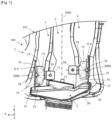
- THE figures 1 to 3 illustrate an example of realization of an arrangement 1 of one or for a body of a motor vehicle 100, in particular an arrangement implemented at the level of a wheel arch 101 of the vehicle 100.
- an arrangement can be implemented at the level of a front wheel arch 101 or at the level of a rear wheel arch 101.
- the arrangement 1 comprises a support 2 for a suspension system of a wheel, not shown, of the vehicle 100, such a support 2 comprising, for example a structure made of pressed sheet metal.
- the arrangement 1 further comprises a shock absorber 3, a body 30 of which is able to be fixed on said support 2 and an indexing device 4.
- the direction designated as longitudinal corresponds to an axis of advancement X in a straight line of the vehicle 100
- the vertical direction corresponds to a vertical axis Z, orthogonal to the axis X and oriented vertically when the vehicle 100 is on horizontal ground.
- the transverse direction corresponds to a Y axis, orthogonal to the X and Z axes.
- the indexing device 4 comprises two distinct parts: a first indexing member 5 and a second indexing member 6.
- indexing member is meant a member configured to allow positioning, that is to say guiding to a predefined suitable position, of the shock absorber 3 within the arrangement 1, in particular relative to the support 2.
- the indexing device 4 ensures that the shock absorber 3 is correctly positioned relative to the support 2 when the shock absorber 3 is approached from the support 2.
- the indexing device 4 is thus configured to be placed on the support 2 prior to the installation of the shock absorber 3. Furthermore, the indexing device 4 according to the invention is intended to remain on the vehicle 100 subsequently to the installation of the shock absorber 3 within the arrangement.
- the first indexing member 5 and the second indexing member 6 are attached and mounted integral with a support, in particular the same support 2. They are particularly configured to indifferently ensure the front indexing and the rear indexing of the shock absorber 3, in particular of the body 30 of the shock absorber 3, relative to the support 2.
- the first indexing member 5 can be mounted integral with the support 2 so as to ensure one of the front indexing or the rear indexing of the shock absorber 3 relative to the support 2
- the second indexing member 6 can be mounted integral with the support 2 so as to ensure the other of the front indexing or the rear indexing of the shock absorber 3 relative to the support 2.
- front and rear are defined in particular along the axis of advancement X of the vehicle 100.
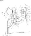
- first indexing member 5 and the second indexing member 6, detailed in more detail in figure 2 And 3 preferably have the shape of squares or angles. They each include a right-angled wing 70 cooperating with the body 30 of the shock absorber 3 so as to ensure the adequate positioning of the latter relative to the support 2, that is to say to ensure its guidance.
- the wing 70 of the first indexing member 5 may have a structure and/or geometry that is symmetrical or substantially symmetrical relative to a primary median plane 5000, specific to the first indexing member 5 and passing by the wing 70.
- a primary median plane 5000 passes through a middle of the wing 70 measured along a direction defined by an axis of extension 500 of the wing 70 of the first indexing member 5.
- a primary median plane 5000 extends perpendicular to the wing 70, that is to say orthogonally to the extension axis 500 of said wing 70.
- the wing 70 of the second indexing member 6 may have a structure and/or geometry that is symmetrical or substantially symmetrical relative to a secondary median plane 6000, in particular distinct from the primary median plane. 5000 and specific to the second indexing member 6.
- a secondary median plane 6000 passes through the wing 70, in particular through a middle of the wing 70, along a direction defined by an axis of extension 600 of the wing 70 of the second indexing member 6.
- a secondary median plane 6000 extends perpendicular to the wing 70, that is to say orthogonal to the axis of extension 600 of said wing 70.
- substantially symmetrical is meant that the wing 70 can present at least part of the following options: dimensions or a shape, relating to the geometry, or all or part of the characteristics such as set out in the present description, relating to the structure, symmetrical relative to the primary median plane 5000 or secondary 6000 of the indexing member 5, 6 considered.
- symmetrical is meant that the wing 70 has dimensions, shape and characteristics as set out in the present description, symmetrical relative to the median plane, primary 5000 or secondary 6000, of the indexing member 5, 6 considered.
- any characteristic described with reference to “an indexing member”, to the “first indexing member 5" or to the “second indexing member 6" may extend to the first indexing member 5 and/or the second indexing member 6.
- similar elements specific to the first indexing member 5 and/or the second indexing member 6 will be indicated by identical references in the different figures.
- first indexing member 5 and the second indexing member 6 can, according to a particular illustrated example, have an identical or substantially identical structure and/or geometry ( s).
- the wing 70 of the first indexing member 5 and/or the wing 70 of the second indexing member 6 comprises(s) a first end 71 and a second end 72 which each delimit the wing 70 considered along of the direction defined by the extension axis 500, 600 which is specific to it.
- the wing 70 further comprises a free main edge 79 which connects such first end 72 and second end 73 together.
- the first end 71 and the second end 72 each include an inclined edge 73, relative to the main free edge 79, these inclined edges 73 each defining, relative to the support 2, a receiving passage 11 and guiding the body 30 of the shock absorber 3.
- such an inclined edge 73 can extend over all or part of the first end 71 on the one hand or the second end 72 on the other hand.
- the main free edge 79 can, as illustrated, connect the inclined edge 73 of the first end 71 and the inclined edge 73 of the second end 72 together.
- inclined edge is meant in particular an edge of the wing 70 extending transversely and at an angle strictly less than 90° with respect to the main free edge 79 and/or with respect to at least one plane orthogonal to the wing. 70.
- said plane can be parallel or substantially parallel to the primary or secondary median plane 5000, 6000 specific to the corresponding indexing member 5, 6.
- a plane considered may be perpendicular or substantially perpendicular to the primary or secondary median plane 5000, 6000 specific to the corresponding indexing member 5, 6.
- a junction zone of the main free edge 79 and the inclined edge 73 or the inclined edges 73 may have a rounding.
- the inclined edge 73 of the first end 71 and the inclined edge 73 of the second end 72 of the wing 7 make it possible to guide the shock absorber 3 at least along two distinct directions, in particular two directions orthogonal to one another. other, up to a suitable position in which the shock absorber 3 can then be fixed to the support 2.
- such inclined edges 73 allow the guidance of the shock absorber 3 along the longitudinal direction X and along the vertical direction Z.
- the inclined edge 73 of the first end 71 of the wing 70 and the inclined edge 73 of the second end 72 of the wing 70 have a at least partially complementary shape of at least part of the body 30 of the shock absorber 3 so as to optimize its guidance and maintenance in the appropriate position.
- the support 2 thus forms a first side of such a receiving passage 11 of the body 30 of the shock absorber 3 while the inclined edge 73 of the first end 71, or of the second end 72, forms a second side, distinct from the first side, of such a reception passage 11.
- each of the first indexing member 5 and second indexing member 6 participates in delimiting two receiving passages 11 each capable of receiving the shock absorber 3 and guiding the adequate positioning, only one of said two passages 11 being used depending on whether the indexing member considered is arranged in the front indexing position or in the rear indexing position.
- the inclined edge 73 of the first end 71 of the wing 70 and the inclined edge 73 of the second end 72 of the wing 70 each have an angle ⁇ of between 20 and 85° relative to at least one part of the support extending to the right of the corresponding inclined edge 73.
- an angle ⁇ is defined relative to a plane, as previously explained, perpendicular to the primary or secondary median plane 5000, 6000 of the corresponding indexing member 5, 6.
- Such a plane can in particular extend parallel to most of the main free edge 79.
- the inclined edge 73 of the first end 71 of the wing 70 and the inclined edge 73 of the second end 72 of the wing 70 each have an angle ⁇ of between 5 and 70° relative to a parallel plane or substantially parallel to the primary or secondary median plane 5000, 6000 of the indexing member 5, 6 considered.
- the inclined edge 73 of the first end 71 of the wing 70 and the inclined edge 73 of the second end 72 of the wing 70 may have an angle ⁇ equal or substantially equal.
- Such an angle ⁇ is particularly suited to a predefined shape of the support 2.
- first indexing member 5 and/or the second indexing member 6 comprise(s) a fixing base 74 of the indexing member 5, 6 considered on the support 2 of the vehicle 100.
- the fixing base 74 is, preferably, planar or substantially planar and configured to cooperate with the support 2.
- the fixing base 74 extends transversely to the wing 70, in particular, according to a particular example, perpendicular to this one. Additionally, the fixing base 74 can be connected to the wing 70. In other words, the fixing base 74 can thus form another wing, distinct from the wing 70, of the form of a square or angle such as than previously exposed.
- the fixing base 74 advantageously has a dimension, measured along the direction defined by the axis of extension 500, 600 considered, smaller than a dimension of the wing 70.
- the fixing base 74 is in particular at least arranged at a central portion, along the direction defined by the axis of extension 500, 600 considered, of the wing 70.
- the fixing base 74 can be made integrally with the wing 70.
- at least the wing 70 and the fixing base 74 form a one-piece assembly so that they cannot be dissociated from one another without resulting in the degradation or even destruction of the indexing member 5, 6.
- the fixing base 74 delimits at least one fixing zone 75 of the indexing member on the support 2.
- the fixing base 74 can delimit a plurality of fixing zones 75 of the indexing member 5, 6 on support 2.
- the first indexing member 5 and/or the second indexing member 6 is/are mounted integral with the support 2 by welding, in particular by at least one welding point.
- the fixing base 74 is dimensioned so as to delimit a fixing zone 75 whose longest dimension is greater than or equal to 20 mm.
- longest dimension we mean a diameter, for a circular or substantially circular fixing zone 75, or a diagonal, for a polygonal fixing zone 75.
- the support 2 advantageously comprises at least one first flat or substantially flat surface 21 configured to allow the fixing of the fixing base 74 of the first indexing member 5 or the fixing base 74 of the second indexing member 6.
- the support 2 comprises, in a similar manner, at least one second flat or substantially flat surface 22 configured to cooperate with the fixing base 74 of the first indexing member. indexing 5 or with the fixing base 74 of the second indexing member 6.
- first surface 21 and second surface 22 can cooperate with all or part of the fixing base 74 considered, that is to say with at least one fixing zone 75 of the fixing base 74 considered.
- Such an arrangement aims in particular to optimize a contact zone, and therefore the connection, between the indexing member 5, 6 and the support 2.
- the angle ⁇ defining the inclined edges 73 as previously exposed can then be defined relative to the flat surface, that is to say relative to the first flat surface 21 or to the second flat surface 22, on which the indexing member 5, 6 considered.
- these can optionally include at least one reinforcement 76.
- the reinforcement 76 extends between the wing 70 and the base fixing 74 of the corresponding indexing member 5, 6, projecting perpendicularly to the fixing base 74 and/or to the wing 70. It can in particular be obtained by stamping the indexing member 5, 6, for example by making a boss in the connecting angle of the wing 70 and the fixing base 74 of the bracket or angle.
- the reinforcement 76 can have a central positioning, along the direction defined by the extension axis 500, 600 considered, within the fixing base 74 and/or the wing 70.
- the reinforcement 76 can then, according to the particular example illustrated, be interposed, along the direction defined by the axis of extension 500, 600 considered, between two distinct fixing zones 75 included in the same fixing portion 74.
- the first indexing member 5 and/or the second indexing member 6 may comprise a plurality of reinforcements 76 connecting the wing 70 to the fixing base 74.
- the first indexing member 5 and/or the second indexing member 6 may comprise a guide tab 77 for the position of the indexing member 5, 6 relative to the support 2.
- the guide tab 77 can extend transversely to the wing 70 of the corresponding indexing member, in particular the guide tab 77 can extend orthogonally to the wing 70 of the indexing member 5, 6 considered.
- the guide tab 77 comprises an opening or perforation 78, in particular substantially in its center, allowing the movement and positioning of the indexing member 5, 6 up to a suitable fixing position on the support 2 during the assembly of arrangement 1 according to the invention.
- a perforation 78 can be configured to cooperate with a tool and/or a machine for assembling at least part of the arrangement according to the invention.
- the guide tab 77 can come from the fixing base 74 of the indexing member.
- the guide tab 77 can extend parallel or substantially parallel to said fixing portion 74.
- the guide tab 77 extends, preferably, opposite the wing 70 relative to the fixing base 74.
- the fixing base 74 is interposed between the wing 70 and the guide tab 77 along at least one direction, in particular, in this case, substantially along the longitudinal direction X when the arrangement is assembled.
- the wing 70, the fixing base 74 and the guide tab 77 of the same indexing member 5, 6 form a single piece assembly.
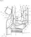
- the first indexing member 5 and the second indexing member 6 of the indexing device 4 are attached and mounted integrally with the support 2 via their base respective fixing 74. Hence, the first indexing member 5 is positioned so as to ensure the front indexing of the shock absorber 3 while the second indexing member 6 is positioned so as to ensure the rear indexing of this same shock absorber 3.
- the first indexing member 5 and the second indexing member 6 of the indexing device 4 make it possible, as previously explained, to ensure indifferently the front indexing and the rear indexing of the shock absorber 3 relative to the support 2, that is to say that the positions of the first indexing member 5 and the second indexing member 6 could be reversed so that the first indexing member 5 is positioned in order to ensure the rear indexing of the shock absorber and that the second indexing member 6 is positioned to ensure the front indexing of the shock absorber.
- Such a positioning alternative is in particular obtained by pivoting of the indexing member 5, 6 considered, such pivoting being able, according to a non-limiting example, to be carried out around an axis of rotation centered on the perforation 78, then by positioning of the fixing base 74 on the first flat surface 21 or the second flat surface 22 of the support with a view to welding the indexing member on the support 2.
- the change in positioning of the indexing member indexing considered from a front indexing position to a rear indexing position, or vice versa may include a pivoting of the indexing member 5, 6 of the order of 120 to 240° around the axis of rotation considered.
- such an axis of rotation can extend parallel to the transverse direction.
- the first indexing member 5 and the second indexing member 6 are thus arranged on either side of a main median plane 2000 of the support 2.
- the first indexing member 5 and the second member of indexing members 6 are arranged so that a distance separating the guide lugs 77 specific to each of the first and second indexing members 5, 6 is less than a distance separating the wing 70 from said indexing members 5, 6 of said median main plan 2000.
- the guide tab 77 and the fixing base 74 specific to each of the first and second indexing members 5, 6 are interposed between the wing 70 of the first indexing member 5 and the wing 70 of the second indexing member 6, in particular along an axis orthogonal to the main median plane 2000 of the support 2.
- first indexing member 5 and/or the second indexing member 6 is/are configured so as to cooperate with distinct parts of the body 30 of the shock absorber 3, in particular distal parts 31, 32 of the body 30 of the shock absorber 3, the most distant from the main median plane 2000 of the support 2.
- the present invention thus proposes an arrangement for a body of a motor vehicle according to independent claim 1.
- Such an arrangement, or device has the advantage of reducing the number of spare part references, thus simplifying the management of spare part stocks and likewise reducing production costs and the risk of errors during assembly.
Landscapes
- Engineering & Computer Science (AREA)
- Chemical & Material Sciences (AREA)
- Combustion & Propulsion (AREA)
- Transportation (AREA)
- Mechanical Engineering (AREA)
- Manufacturing & Machinery (AREA)
- Vehicle Body Suspensions (AREA)
- Fluid-Damping Devices (AREA)
Claims (11)
- Anordnung (1) für einen Rahmen eines Kraftfahrzeugs (100), wobei die Anordnung (1) Folgendes umfasst: einen Träger (2) für ein Aufhängungssystem eines Fahrzeugrads (100), einen Stoßdämpfer (3) mit einem Körper (30), der am Träger (2) befestigt sein kann, und eine Indexierungsvorrichtung (4), die ein erstes Indexierungsorgan (5) und ein zweites Indexierungsorgan (6) umfasst, die am Träger (2) angebracht und fest mit diesem verbunden sind, dadurch gekennzeichnet, dass das erste Indexierungsorgan (5) und das zweite Indexierungsorgan (6) jeweils dazu ausgelegt sind, unterschiedslos die vordere und die hintere Indexierung des Stoßdämpfers (3), insbesondere des Körpers (30) des Stoßdämpfers (3), in Bezug auf den Träger (2) zu gewährleisten, um seine adäquate Positionierung in Bezug auf den Träger (2) zu gewährleisten.
- Anordnung (1) nach dem vorangehenden Anspruch, wobei das erste Indexierungsorgan (5) und das zweite Indexierungsorgan (6) jeweils einen Flügel (70) umfassen, der mit dem Körper (30) des Stoßdämpfers (3) zusammenwirkt, um seine adäquate Positionierung in Bezug auf den Träger (2) zu gewährleisten.
- Anordnung (1) nach dem vorangehenden Anspruch, wobei zumindest der Flügel (70) des ersten Indexierungsorgans (5) und/oder der Flügel (70) des zweiten Indexierungsorgans (6) eine Struktur und/oder eine Geometrie aufweisen, die in Bezug auf eine Mittelebene (5000, 6000), die durch den entsprechenden Flügel (70) des jeweiligen Indexierungsorgans (5, 6) verläuft, symmetrisch oder im Wesentlichen symmetrisch sind.
- Anordnung (1) nach einem der Ansprüche 2 oder 3, wobei ein erstes Ende (71) und ein zweites Ende (72) des Flügels (70) des ersten Indexierungsorgans (5) und/oder des Flügels (70) des zweiten Indexierungsorgans (6) jeweils eine Kante (73) aufweisen, die in Bezug auf freie Hauptkante (79) des Flügels (70) geneigt ist, wobei die freie Hauptkante (79) das erste Ende (71) und das zweite Ende (72) miteinander verbindet und wobei die geneigte Kante (73) in Bezug auf den Träger (2) einen Durchgang (11) zur Aufnahme und Führung des Körpers (30) des Stoßdämpfers (3) definiert.
- Anordnung (1) nach dem vorangehenden Anspruch, wobei die geneigte Kante (73) des ersten Endes (71) des Flügels (70) und die geneigte Kante (73) des zweiten Endes (72) des Flügels (70) des ersten Indexierungsorgans (5) und/oder des Flügels (70) des zweiten Indexierungsorgans (6) eine Form aufweisen, die zu einem Teil des Körpers (30) des Stoßdämpfers (3) komplementär ist.
- Anordnung (1) nach Anspruch 4 oder 5, wobei die geneigte Kante (73) des ersten Endes (71) des Flügels (70) und die geneigte Kante (73) des zweiten Endes (72) des Flügels (70) des ersten Indexierungsorgans (5) und/oder des Flügels (70) des zweiten Indexierungsorgans (6) jeweils einen Winkel α relativ zu einem Teil des Trägers (2) aufweisen, wobei sich die Winkel direkt von der entsprechenden geneigten Kante (73) erstrecken und gleich oder im Wesentlichen gleich sind, wobei die Winkel α zwischen 20 und 85° betragen.
- Anordnung (1) nach einem der Ansprüche 2 bis 6, wobei das erste Indexierungsorgan (5) und/oder das zweite Indexierungsorgan (6) einen ebenen oder im Wesentlichen ebenen Befestigungssockel (74) aufweisen, der zumindest einen Befestigungsbereich (75) des entsprechenden Indexierungsorgans (5, 6) auf dem Träger (2) begrenzt, wobei der Befestigungssockel (74) mit dem Flügel (70) verbunden ist.
- Anordnung (1) nach dem vorangehenden Anspruch, wobei das erste Indexierungsorgan (5) und/oder das zweite Indexierungsorgan (6) zumindest eine Verstärkung (76) aufweisen, die sich zwischen dem Flügel (70) und dem Befestigungssockel (74) des entsprechenden Indexierungsorgans (5, 6) erstreckt.
- Anordnung (1) nach einem der Ansprüche 2 bis 8, wobei das erste Indexierungsorgan (5) und/oder das zweite Indexierungsorgan (6) eine Lasche (77) zur Führung der Position des betreffenden Indexierungsorgans (5, 6) in Bezug auf den Träger (2) umfassen, wobei sich die Führungslasche (77) quer zum Flügel (70) des entsprechenden Indexierungsorgans (5, 6) erstreckt und/oder wobei die Führungslasche (77) vom Befestigungssockel (74) des entsprechenden Indexierungsorgans (5, 6) ausgeht und sich parallel oder im Wesentlichen parallel zum Befestigungsabschnitt (74) erstreckt.
- Anordnung (1) nach einem der vorangehenden Ansprüche, wobei das erste Indexierungsorgan (5) und das zweite Indexierungsorgan (6) eine Struktur und/oder eine Geometrie aufweisen, die identisch oder im Wesentlichen identisch sind.
- Kraftfahrzeug (100), umfassend mindestens eine Anordnung (1) nach einem der Ansprüche 1 bis 10.
Applications Claiming Priority (1)
| Application Number | Priority Date | Filing Date | Title |
|---|---|---|---|
| FR2012511A FR3116791B1 (fr) | 2020-12-02 | 2020-12-02 | Agencement pour une caisse d’un véhicule automobile et dispositif d’indexage pour un tel agencement. |
Publications (2)
| Publication Number | Publication Date |
|---|---|
| EP4008609A1 EP4008609A1 (de) | 2022-06-08 |
| EP4008609B1 true EP4008609B1 (de) | 2024-07-17 |
Family
ID=74045982
Family Applications (1)
| Application Number | Title | Priority Date | Filing Date |
|---|---|---|---|
| EP21211376.5A Active EP4008609B1 (de) | 2020-12-02 | 2021-11-30 | Anordnung für eine karosserie eines kraftfahrzeugs |
Country Status (2)
| Country | Link |
|---|---|
| EP (1) | EP4008609B1 (de) |
| FR (1) | FR3116791B1 (de) |
Family Cites Families (3)
| Publication number | Priority date | Publication date | Assignee | Title |
|---|---|---|---|---|
| JP2600978B2 (ja) * | 1990-05-25 | 1997-04-16 | 日産自動車株式会社 | サスペンションのアッパリンク支持部構造 |
| KR100335956B1 (ko) * | 1999-11-23 | 2002-05-10 | 이계안 | 차량의 리어 서스펜션 장착 브라켓트 |
| JP4094588B2 (ja) * | 2004-08-03 | 2008-06-04 | 本田技研工業株式会社 | 車両用リヤサスペンションの取付構造 |
-
2020
- 2020-12-02 FR FR2012511A patent/FR3116791B1/fr active Active
-
2021
- 2021-11-30 EP EP21211376.5A patent/EP4008609B1/de active Active
Also Published As
| Publication number | Publication date |
|---|---|
| EP4008609A1 (de) | 2022-06-08 |
| FR3116791A1 (fr) | 2022-06-03 |
| FR3116791B1 (fr) | 2023-01-06 |
Similar Documents
| Publication | Publication Date | Title |
|---|---|---|
| EP1544035B1 (de) | Vorderer Karosserieaufbau eines Kraftfahrzeuges mit verbesserten Befestigungs- und Lagejustiermitteln, und Kraftfahrzeug ausgestattet mit einem solchen Aufbau | |
| EP3944985B1 (de) | Fahrzeugsitz | |
| EP4008609B1 (de) | Anordnung für eine karosserie eines kraftfahrzeugs | |
| EP1689598B1 (de) | Flexible achse mit einer quersteifigkeit, die mit hilfe von mindestens einem federtellerformteil erhöht wird, federteller und entsprechendes fahrzeug | |
| EP2890906A1 (de) | Ring zur befestigung eines riegels an einem träger und anordnung daraus | |
| FR3094326A1 (fr) | Structure arrière de caisse de véhicule automobile comportant des platines de renfort fixées sur les longeronnets avant | |
| EP4168270A1 (de) | Kraftfahrzeugsitz-befestigungsbügel, der für verschiedene varianten einer fahrzeugreichweite verwendbar ist | |
| FR3139783A1 (fr) | extension de longeronnet arrière pour véhicule automobile | |
| FR3073436A1 (fr) | Dispositif de pilotage hyperstatique entre deux orifices | |
| EP4538117B1 (de) | Stossfängerkappe und stossfängeranordnung für ein kraftfahrzeug | |
| EP2868519B1 (de) | Versenkbarer Sitz mit Kippsicherung | |
| FR3145335A1 (fr) | Déflecteur aéraulique pour véhicule automobile | |
| EP2922742B1 (de) | Vorrichtung zur aufnahme eines motorfahrzeugaufhängungselements, ausrüstung mit zwei identischen vorrichtungen und verfahren zur herstellung der vorrichtung | |
| EP3628514B1 (de) | Plastisch deformierbare konsole zur befestigung eines kraftfahrzeugrades | |
| FR3102418A1 (fr) | Armature de siège d’un véhicule automobile et siège de véhicule associé | |
| FR3156418A1 (fr) | Dispositif de déport de la zone d’accueil d’un appui cric de véhicule automobile | |
| FR3148984A1 (fr) | Déflecteur aéraulique pour véhicule automobile | |
| EP4729390A1 (de) | Befestigungsteil einer lenksäule auf einem träger eines kraftfahrzeugs, zugehörige anordnung und herstellungsverfahren | |
| FR3160665A1 (fr) | Ensemble pour véhicule automobile et véhicule comprenant un tel ensemble | |
| WO2023208726A1 (fr) | Ensemble de connexion d'un système d'essuyage | |
| EP4538151A1 (de) | Anordnung für ein kraftfahrzeug mit einer verriegelungsanordnung einer haube und einem tragrahmenelement | |
| FR3119587A1 (fr) | Adaptateur d’un système d’essuyage | |
| FR3159786A1 (fr) | Arrangement de châssis pour véhicule automobile | |
| FR3154668A1 (fr) | Structure de véhicule avec support d’accoudoir fixé au passage de roue arrière | |
| FR3146295A1 (fr) | Dispositif d’ancrage d’au moins un siège arrière rabattable de véhicule |
Legal Events
| Date | Code | Title | Description |
|---|---|---|---|
| PUAI | Public reference made under article 153(3) epc to a published international application that has entered the european phase |
Free format text: ORIGINAL CODE: 0009012 |
|
| STAA | Information on the status of an ep patent application or granted ep patent |
Free format text: STATUS: THE APPLICATION HAS BEEN PUBLISHED |
|
| AK | Designated contracting states |
Kind code of ref document: A1 Designated state(s): AL AT BE BG CH CY CZ DE DK EE ES FI FR GB GR HR HU IE IS IT LI LT LU LV MC MK MT NL NO PL PT RO RS SE SI SK SM TR |
|
| RAP3 | Party data changed (applicant data changed or rights of an application transferred) |
Owner name: RENAULT S.A.S |
|
| STAA | Information on the status of an ep patent application or granted ep patent |
Free format text: STATUS: REQUEST FOR EXAMINATION WAS MADE |
|
| 17P | Request for examination filed |
Effective date: 20221114 |
|
| RBV | Designated contracting states (corrected) |
Designated state(s): AL AT BE BG CH CY CZ DE DK EE ES FI FR GB GR HR HU IE IS IT LI LT LU LV MC MK MT NL NO PL PT RO RS SE SI SK SM TR |
|
| STAA | Information on the status of an ep patent application or granted ep patent |
Free format text: STATUS: EXAMINATION IS IN PROGRESS |
|
| 17Q | First examination report despatched |
Effective date: 20230419 |
|
| P01 | Opt-out of the competence of the unified patent court (upc) registered |
Effective date: 20230608 |
|
| GRAP | Despatch of communication of intention to grant a patent |
Free format text: ORIGINAL CODE: EPIDOSNIGR1 |
|
| STAA | Information on the status of an ep patent application or granted ep patent |
Free format text: STATUS: GRANT OF PATENT IS INTENDED |
|
| INTG | Intention to grant announced |
Effective date: 20240208 |
|
| GRAS | Grant fee paid |
Free format text: ORIGINAL CODE: EPIDOSNIGR3 |
|
| GRAA | (expected) grant |
Free format text: ORIGINAL CODE: 0009210 |
|
| STAA | Information on the status of an ep patent application or granted ep patent |
Free format text: STATUS: THE PATENT HAS BEEN GRANTED |
|
| AK | Designated contracting states |
Kind code of ref document: B1 Designated state(s): AL AT BE BG CH CY CZ DE DK EE ES FI FR GB GR HR HU IE IS IT LI LT LU LV MC MK MT NL NO PL PT RO RS SE SI SK SM TR |
|
| REG | Reference to a national code |
Ref country code: CH Ref legal event code: EP |
|
| REG | Reference to a national code |
Ref country code: DE Ref legal event code: R096 Ref document number: 602021015775 Country of ref document: DE |
|
| REG | Reference to a national code |
Ref country code: IE Ref legal event code: FG4D Free format text: LANGUAGE OF EP DOCUMENT: FRENCH |
|
| REG | Reference to a national code |
Ref country code: LT Ref legal event code: MG9D |
|
| REG | Reference to a national code |
Ref country code: NL Ref legal event code: MP Effective date: 20240717 |
|
| PG25 | Lapsed in a contracting state [announced via postgrant information from national office to epo] |
Ref country code: PT Free format text: LAPSE BECAUSE OF FAILURE TO SUBMIT A TRANSLATION OF THE DESCRIPTION OR TO PAY THE FEE WITHIN THE PRESCRIBED TIME-LIMIT Effective date: 20241118 |
|
| REG | Reference to a national code |
Ref country code: AT Ref legal event code: MK05 Ref document number: 1703863 Country of ref document: AT Kind code of ref document: T Effective date: 20240717 |
|
| PG25 | Lapsed in a contracting state [announced via postgrant information from national office to epo] |
Ref country code: NL Free format text: LAPSE BECAUSE OF FAILURE TO SUBMIT A TRANSLATION OF THE DESCRIPTION OR TO PAY THE FEE WITHIN THE PRESCRIBED TIME-LIMIT Effective date: 20240717 |
|
| PG25 | Lapsed in a contracting state [announced via postgrant information from national office to epo] |
Ref country code: PT Free format text: LAPSE BECAUSE OF FAILURE TO SUBMIT A TRANSLATION OF THE DESCRIPTION OR TO PAY THE FEE WITHIN THE PRESCRIBED TIME-LIMIT Effective date: 20241118 Ref country code: NL Free format text: LAPSE BECAUSE OF FAILURE TO SUBMIT A TRANSLATION OF THE DESCRIPTION OR TO PAY THE FEE WITHIN THE PRESCRIBED TIME-LIMIT Effective date: 20240717 |
|
| PG25 | Lapsed in a contracting state [announced via postgrant information from national office to epo] |
Ref country code: NO Free format text: LAPSE BECAUSE OF FAILURE TO SUBMIT A TRANSLATION OF THE DESCRIPTION OR TO PAY THE FEE WITHIN THE PRESCRIBED TIME-LIMIT Effective date: 20241017 |
|
| PG25 | Lapsed in a contracting state [announced via postgrant information from national office to epo] |
Ref country code: GR Free format text: LAPSE BECAUSE OF FAILURE TO SUBMIT A TRANSLATION OF THE DESCRIPTION OR TO PAY THE FEE WITHIN THE PRESCRIBED TIME-LIMIT Effective date: 20241018 Ref country code: PL Free format text: LAPSE BECAUSE OF FAILURE TO SUBMIT A TRANSLATION OF THE DESCRIPTION OR TO PAY THE FEE WITHIN THE PRESCRIBED TIME-LIMIT Effective date: 20240717 Ref country code: FI Free format text: LAPSE BECAUSE OF FAILURE TO SUBMIT A TRANSLATION OF THE DESCRIPTION OR TO PAY THE FEE WITHIN THE PRESCRIBED TIME-LIMIT Effective date: 20240717 |
|
| PG25 | Lapsed in a contracting state [announced via postgrant information from national office to epo] |
Ref country code: BG Free format text: LAPSE BECAUSE OF FAILURE TO SUBMIT A TRANSLATION OF THE DESCRIPTION OR TO PAY THE FEE WITHIN THE PRESCRIBED TIME-LIMIT Effective date: 20240717 |
|
| PG25 | Lapsed in a contracting state [announced via postgrant information from national office to epo] |
Ref country code: LV Free format text: LAPSE BECAUSE OF FAILURE TO SUBMIT A TRANSLATION OF THE DESCRIPTION OR TO PAY THE FEE WITHIN THE PRESCRIBED TIME-LIMIT Effective date: 20240717 |
|
| PG25 | Lapsed in a contracting state [announced via postgrant information from national office to epo] |
Ref country code: IS Free format text: LAPSE BECAUSE OF FAILURE TO SUBMIT A TRANSLATION OF THE DESCRIPTION OR TO PAY THE FEE WITHIN THE PRESCRIBED TIME-LIMIT Effective date: 20241117 Ref country code: AT Free format text: LAPSE BECAUSE OF FAILURE TO SUBMIT A TRANSLATION OF THE DESCRIPTION OR TO PAY THE FEE WITHIN THE PRESCRIBED TIME-LIMIT Effective date: 20240717 |
|
| PG25 | Lapsed in a contracting state [announced via postgrant information from national office to epo] |
Ref country code: HR Free format text: LAPSE BECAUSE OF FAILURE TO SUBMIT A TRANSLATION OF THE DESCRIPTION OR TO PAY THE FEE WITHIN THE PRESCRIBED TIME-LIMIT Effective date: 20240717 |
|
| PG25 | Lapsed in a contracting state [announced via postgrant information from national office to epo] |
Ref country code: RS Free format text: LAPSE BECAUSE OF FAILURE TO SUBMIT A TRANSLATION OF THE DESCRIPTION OR TO PAY THE FEE WITHIN THE PRESCRIBED TIME-LIMIT Effective date: 20241017 Ref country code: ES Free format text: LAPSE BECAUSE OF FAILURE TO SUBMIT A TRANSLATION OF THE DESCRIPTION OR TO PAY THE FEE WITHIN THE PRESCRIBED TIME-LIMIT Effective date: 20240717 |
|
| PG25 | Lapsed in a contracting state [announced via postgrant information from national office to epo] |
Ref country code: RS Free format text: LAPSE BECAUSE OF FAILURE TO SUBMIT A TRANSLATION OF THE DESCRIPTION OR TO PAY THE FEE WITHIN THE PRESCRIBED TIME-LIMIT Effective date: 20241017 Ref country code: PL Free format text: LAPSE BECAUSE OF FAILURE TO SUBMIT A TRANSLATION OF THE DESCRIPTION OR TO PAY THE FEE WITHIN THE PRESCRIBED TIME-LIMIT Effective date: 20240717 Ref country code: NO Free format text: LAPSE BECAUSE OF FAILURE TO SUBMIT A TRANSLATION OF THE DESCRIPTION OR TO PAY THE FEE WITHIN THE PRESCRIBED TIME-LIMIT Effective date: 20241017 Ref country code: LV Free format text: LAPSE BECAUSE OF FAILURE TO SUBMIT A TRANSLATION OF THE DESCRIPTION OR TO PAY THE FEE WITHIN THE PRESCRIBED TIME-LIMIT Effective date: 20240717 Ref country code: IS Free format text: LAPSE BECAUSE OF FAILURE TO SUBMIT A TRANSLATION OF THE DESCRIPTION OR TO PAY THE FEE WITHIN THE PRESCRIBED TIME-LIMIT Effective date: 20241117 Ref country code: HR Free format text: LAPSE BECAUSE OF FAILURE TO SUBMIT A TRANSLATION OF THE DESCRIPTION OR TO PAY THE FEE WITHIN THE PRESCRIBED TIME-LIMIT Effective date: 20240717 Ref country code: GR Free format text: LAPSE BECAUSE OF FAILURE TO SUBMIT A TRANSLATION OF THE DESCRIPTION OR TO PAY THE FEE WITHIN THE PRESCRIBED TIME-LIMIT Effective date: 20241018 Ref country code: FI Free format text: LAPSE BECAUSE OF FAILURE TO SUBMIT A TRANSLATION OF THE DESCRIPTION OR TO PAY THE FEE WITHIN THE PRESCRIBED TIME-LIMIT Effective date: 20240717 Ref country code: ES Free format text: LAPSE BECAUSE OF FAILURE TO SUBMIT A TRANSLATION OF THE DESCRIPTION OR TO PAY THE FEE WITHIN THE PRESCRIBED TIME-LIMIT Effective date: 20240717 Ref country code: BG Free format text: LAPSE BECAUSE OF FAILURE TO SUBMIT A TRANSLATION OF THE DESCRIPTION OR TO PAY THE FEE WITHIN THE PRESCRIBED TIME-LIMIT Effective date: 20240717 Ref country code: AT Free format text: LAPSE BECAUSE OF FAILURE TO SUBMIT A TRANSLATION OF THE DESCRIPTION OR TO PAY THE FEE WITHIN THE PRESCRIBED TIME-LIMIT Effective date: 20240717 |
|
| PG25 | Lapsed in a contracting state [announced via postgrant information from national office to epo] |
Ref country code: RO Free format text: LAPSE BECAUSE OF FAILURE TO SUBMIT A TRANSLATION OF THE DESCRIPTION OR TO PAY THE FEE WITHIN THE PRESCRIBED TIME-LIMIT Effective date: 20240717 Ref country code: DK Free format text: LAPSE BECAUSE OF FAILURE TO SUBMIT A TRANSLATION OF THE DESCRIPTION OR TO PAY THE FEE WITHIN THE PRESCRIBED TIME-LIMIT Effective date: 20240717 Ref country code: SM Free format text: LAPSE BECAUSE OF FAILURE TO SUBMIT A TRANSLATION OF THE DESCRIPTION OR TO PAY THE FEE WITHIN THE PRESCRIBED TIME-LIMIT Effective date: 20240717 |
|
| REG | Reference to a national code |
Ref country code: DE Ref legal event code: R097 Ref document number: 602021015775 Country of ref document: DE |
|
| PG25 | Lapsed in a contracting state [announced via postgrant information from national office to epo] |
Ref country code: EE Free format text: LAPSE BECAUSE OF FAILURE TO SUBMIT A TRANSLATION OF THE DESCRIPTION OR TO PAY THE FEE WITHIN THE PRESCRIBED TIME-LIMIT Effective date: 20240717 |
|
| PG25 | Lapsed in a contracting state [announced via postgrant information from national office to epo] |
Ref country code: CZ Free format text: LAPSE BECAUSE OF FAILURE TO SUBMIT A TRANSLATION OF THE DESCRIPTION OR TO PAY THE FEE WITHIN THE PRESCRIBED TIME-LIMIT Effective date: 20240717 |
|
| PG25 | Lapsed in a contracting state [announced via postgrant information from national office to epo] |
Ref country code: SK Free format text: LAPSE BECAUSE OF FAILURE TO SUBMIT A TRANSLATION OF THE DESCRIPTION OR TO PAY THE FEE WITHIN THE PRESCRIBED TIME-LIMIT Effective date: 20240717 |
|
| PLBE | No opposition filed within time limit |
Free format text: ORIGINAL CODE: 0009261 |
|
| STAA | Information on the status of an ep patent application or granted ep patent |
Free format text: STATUS: NO OPPOSITION FILED WITHIN TIME LIMIT |
|
| 26N | No opposition filed |
Effective date: 20250422 |
|
| REG | Reference to a national code |
Ref country code: CH Ref legal event code: PL |
|
| PG25 | Lapsed in a contracting state [announced via postgrant information from national office to epo] |
Ref country code: MC Free format text: LAPSE BECAUSE OF FAILURE TO SUBMIT A TRANSLATION OF THE DESCRIPTION OR TO PAY THE FEE WITHIN THE PRESCRIBED TIME-LIMIT Effective date: 20240717 |
|
| PG25 | Lapsed in a contracting state [announced via postgrant information from national office to epo] |
Ref country code: LU Free format text: LAPSE BECAUSE OF NON-PAYMENT OF DUE FEES Effective date: 20241130 |
|
| REG | Reference to a national code |
Ref country code: CH Ref legal event code: PL |
|
| PG25 | Lapsed in a contracting state [announced via postgrant information from national office to epo] |
Ref country code: CH Free format text: LAPSE BECAUSE OF NON-PAYMENT OF DUE FEES Effective date: 20241130 |
|
| REG | Reference to a national code |
Ref country code: BE Ref legal event code: MM Effective date: 20241130 |
|
| PG25 | Lapsed in a contracting state [announced via postgrant information from national office to epo] |
Ref country code: SE Free format text: LAPSE BECAUSE OF FAILURE TO SUBMIT A TRANSLATION OF THE DESCRIPTION OR TO PAY THE FEE WITHIN THE PRESCRIBED TIME-LIMIT Effective date: 20240717 |
|
| PG25 | Lapsed in a contracting state [announced via postgrant information from national office to epo] |
Ref country code: BE Free format text: LAPSE BECAUSE OF NON-PAYMENT OF DUE FEES Effective date: 20241130 |
|
| PG25 | Lapsed in a contracting state [announced via postgrant information from national office to epo] |
Ref country code: IE Free format text: LAPSE BECAUSE OF NON-PAYMENT OF DUE FEES Effective date: 20241130 |
|
| PGFP | Annual fee paid to national office [announced via postgrant information from national office to epo] |
Ref country code: DE Payment date: 20251119 Year of fee payment: 5 |
|
| PGFP | Annual fee paid to national office [announced via postgrant information from national office to epo] |
Ref country code: GB Payment date: 20251121 Year of fee payment: 5 |
|
| PGFP | Annual fee paid to national office [announced via postgrant information from national office to epo] |
Ref country code: FR Payment date: 20251126 Year of fee payment: 5 |
|
| PG25 | Lapsed in a contracting state [announced via postgrant information from national office to epo] |
Ref country code: IT Free format text: LAPSE BECAUSE OF FAILURE TO SUBMIT A TRANSLATION OF THE DESCRIPTION OR TO PAY THE FEE WITHIN THE PRESCRIBED TIME-LIMIT Effective date: 20240717 |
|
| PG25 | Lapsed in a contracting state [announced via postgrant information from national office to epo] |
Ref country code: CY Free format text: LAPSE BECAUSE OF FAILURE TO SUBMIT A TRANSLATION OF THE DESCRIPTION OR TO PAY THE FEE WITHIN THE PRESCRIBED TIME-LIMIT; INVALID AB INITIO Effective date: 20211130 |