EP4008622B1 - Mécanisme de commutation arrière destiné à la liaison coaxiale à un cadre de bicyclette - Google Patents
Mécanisme de commutation arrière destiné à la liaison coaxiale à un cadre de bicyclette Download PDFInfo
- Publication number
- EP4008622B1 EP4008622B1 EP21401052.2A EP21401052A EP4008622B1 EP 4008622 B1 EP4008622 B1 EP 4008622B1 EP 21401052 A EP21401052 A EP 21401052A EP 4008622 B1 EP4008622 B1 EP 4008622B1
- Authority
- EP
- European Patent Office
- Prior art keywords
- adapter
- base element
- nut
- bolt
- mounting portion
- Prior art date
- Legal status (The legal status is an assumption and is not a legal conclusion. Google has not performed a legal analysis and makes no representation as to the accuracy of the status listed.)
- Active
Links
Images


Classifications
-
- B—PERFORMING OPERATIONS; TRANSPORTING
- B62—LAND VEHICLES FOR TRAVELLING OTHERWISE THAN ON RAILS
- B62M—RIDER PROPULSION OF WHEELED VEHICLES OR SLEDGES; POWERED PROPULSION OF SLEDGES OR SINGLE-TRACK CYCLES; TRANSMISSIONS SPECIALLY ADAPTED FOR SUCH VEHICLES
- B62M9/00—Transmissions characterised by use of an endless chain, belt, or the like
- B62M9/04—Transmissions characterised by use of an endless chain, belt, or the like of changeable ratio
- B62M9/06—Transmissions characterised by use of an endless chain, belt, or the like of changeable ratio using a single chain, belt, or the like
- B62M9/10—Transmissions characterised by use of an endless chain, belt, or the like of changeable ratio using a single chain, belt, or the like involving different-sized wheels, e.g. rear sprocket chain wheels selectively engaged by the chain, belt, or the like
- B62M9/12—Transmissions characterised by use of an endless chain, belt, or the like of changeable ratio using a single chain, belt, or the like involving different-sized wheels, e.g. rear sprocket chain wheels selectively engaged by the chain, belt, or the like the chain, belt, or the like being laterally shiftable, e.g. using a rear derailleur
- B62M9/121—Rear derailleurs
- B62M9/126—Chain guides; Mounting thereof
-
- B—PERFORMING OPERATIONS; TRANSPORTING
- B62—LAND VEHICLES FOR TRAVELLING OTHERWISE THAN ON RAILS
- B62M—RIDER PROPULSION OF WHEELED VEHICLES OR SLEDGES; POWERED PROPULSION OF SLEDGES OR SINGLE-TRACK CYCLES; TRANSMISSIONS SPECIALLY ADAPTED FOR SUCH VEHICLES
- B62M9/00—Transmissions characterised by use of an endless chain, belt, or the like
- B62M9/04—Transmissions characterised by use of an endless chain, belt, or the like of changeable ratio
- B62M9/06—Transmissions characterised by use of an endless chain, belt, or the like of changeable ratio using a single chain, belt, or the like
- B62M9/10—Transmissions characterised by use of an endless chain, belt, or the like of changeable ratio using a single chain, belt, or the like involving different-sized wheels, e.g. rear sprocket chain wheels selectively engaged by the chain, belt, or the like
- B62M9/12—Transmissions characterised by use of an endless chain, belt, or the like of changeable ratio using a single chain, belt, or the like involving different-sized wheels, e.g. rear sprocket chain wheels selectively engaged by the chain, belt, or the like the chain, belt, or the like being laterally shiftable, e.g. using a rear derailleur
- B62M9/121—Rear derailleurs
- B62M9/125—Mounting the derailleur on the frame
-
- B—PERFORMING OPERATIONS; TRANSPORTING
- B62—LAND VEHICLES FOR TRAVELLING OTHERWISE THAN ON RAILS
- B62K—CYCLES; CYCLE FRAMES; CYCLE STEERING DEVICES; RIDER-OPERATED TERMINAL CONTROLS SPECIALLY ADAPTED FOR CYCLES; CYCLE AXLE SUSPENSIONS; CYCLE SIDECARS, FORECARS, OR THE LIKE
- B62K3/00—Bicycles
- B62K3/02—Frames
Definitions
- a bicycle may be equipped with a drive assembly, such as a chain drive.
- Bicycle drive assemblies may be used to transfer torque from a rider to a rear wheel to propel the bicycle.
- a drive assembly may transfer torque from a front sprocket assembly via a chain to a rear sprocket or pinion, such as a pinion of a sprocket cassette or sprocket pack, to drive a rear wheel.
- a drive assembly may be referred to as a drivetrain.
- Bicycle sprocket assemblies may include one or more individual sprockets.
- the front sprockets are commonly referred to as chainrings.
- Chainrings may be attached using a variety of fastening devices.
- a chainring may be attached using chainring bolts or mounted directly to the crank of a bicycle.
- the rear sprockets are often referred to as pinions.
- a plurality of rear sprockets or pinions may be referred to as a cassette, pinion cassette, or pinion pack.
- Such a cassette is typically configured to be attached to a freewheel portion of a rear wheel.
- a cassette may be attached to a freewheel body of a rear wheel using a splined and/or threaded connection.
- a front chainring assembly may have a single chainring that particular sprocket of the rear sprocket cassette.
- the chain connects the single chainring to that substantially aligned single rear sprocket, the chain is subject to little or no lateral loading.
- the chain is moved laterally to another sprocket of the cassette, e.g. by a rear derailleur or rear derailleur of a drivetrain derailleur, the chain experiences some lateral loading. Similar lateral loadings on the chain occur when the front chainring assembly has multiple chainrings between which the chain is moved by a front derailleur or front derailleur of the derailleur.
- a rear derailleur usually has the following structure for this purpose. There is a base element, also known in the technical field as a B-knuckle, with which the derailleur is mounted on the bicycle.
- a movable element also known in the technical field as a P-knuckle, which is movably coupled to the base element, and a chain guide, usually designed as a so-called chain cage, which is movably coupled to the movable element for rotation relative to a rotation axis.
- the movable member is movable in a lateral (axial) direction to move the chain guide along the pinions of the pinion set so that the chain can be transferred from a starting pinion to a target pinion.
- the chain guide is elastically pre-tensioned by a tension spring or the like in a rotational direction, namely in the direction of tension of the bicycle chain guided by the chain guide, in order to keep the chain in the tensioned state or to restore the tensioned state after a previous state of insufficient chain tension.
- This direction of rotation or swivel is also referred to here as the "chain tensioning direction". Twisting the chain guide in this direction increases the chain tension and at the same time reduces the tension of the tension spring acting on the chain guide.
- the chain guide will assume different pivoting positions relative to the moving element with respect to the axis of rotation.
- Impacts on the chain and the chain guide arise not only from switching the derailleur by transferring the chain between different pinions of the pinion set, but also from the driving itself.
- the derailleur and the chain are exposed to impacts and vibrations that can act on the chain guide in a direction opposite to the "chain tensioning direction". Twisting the chain guide in this direction opposite to the "chain tensioning direction” increases the tension of the tension spring acting on the chain guide and leads directly to a reduction in the chain tension (for example if a direct impact on the chain guide twists it in this direction) or at least to a considerable risk of a subsequent reduction in the chain tension below the necessary level.
- Negative consequences can be a drop in the chain tension with undesirable play or "slackness" of the chain, in extreme cases even to the point of the chain jumping off the pinion set.
- the rear derailleur In the case of a frictional fixation of the rear derailleur to the bicycle frame in relation to the intended angular position of the derailleur, namely the angular position in relation to the forward or backward direction of the bicycle or in the "chain tensioning direction” or against the “chain tensioning direction", the rear derailleur can be subjected to impacts on uneven terrain or by branches or the like protruding into the path or in the event of a fall. Impacts exerted may lead to an undesirable adjustment of the angular position of the rear derailleur, which is, however, generally preferable to the risk of damage to the derailleur caused by such impacts in the case of a positive fixation of the rear derailleur in relation to this angular position.
- a single component can serve as a reference for the alignment of various other components of the drive assembly.
- both a derailleur and a cassette can be aligned or mounted coaxially to an axle. Aligning a component of the drivetrain, such as the derailleur, to that axle can reduce inaccuracies in different applications due to tolerance variations in the wheels or frame.
- Coaxial alignment of the derailleur with the wheel axle or cassette can also facilitate uniform radial spacing between parts of the derailleur and cassette across different pivot angles of the derailleur.
- the drive assembly can also be configured for rigidity in order to increase precision and/or improve the relative alignment of components.
- relevant components and elements of the rear derailleur, the rear wheel axle assembly with the rear hub and the sprocket cassette of the rear wheel and the frame interfaces of the rear triangle of the bicycle frame associated therewith can be configured in relation to one another in such a way that, on the one hand, the rear derailleur is reliably and, to the maximum extent harmless, correctly positioned and mounted on the frame relative to the sprocket cassette and the chain running over it, depending on tolerances, and, at the same time, good rigidity is achieved so that this correct Positioning is maintained even when driving, despite possibly greater and changing loads, depending on the surface on which you are driving.
- a correspondingly coordinated configuration of the so-called B-knuckle (or base element) of a rear derailleur i.e. the subcomponent of a rear derailleur that is mounted on an associated frame interface, the rear triangle of the bicycle frame and especially its frame interfaces to which the rear wheel axle assembly of the rear wheel and the rear derailleur are mounted, and the rear wheel axle assembly is possible in order to meet requirements under the aforementioned objectives of correct positioning and alignment, precision and rigidity.
- the present invention generally relates to a rear derailleur of a bicycle derailleur and the manner of mounting the rear derailleur in relation to a rear wheel axle on a bicycle frame, and thus also to a bicycle frame of a corresponding bicycle having a suitable frame interface for the rear derailleur.
- rear derailleur hanger that was separate from the frame or part of the rear frame, offset radially from the rear wheel axle and thus not coaxial with the rear wheel axle.
- the derailleur hanger also known as a "hanger”
- the base element can be rotated around the B-axis relative to the derailleur hanger.
- the applicant SRAM Deutschland GmbH has developed a new type of rear derailleur for coaxial mounting in relation to the rear wheel axle on a rear frame of a correspondingly designed bicycle frame, to which pending patent applications are directed.
- the bicycle frame has a special interface for the rear derailleur on the rear frame, which at the same time, with the assistance of a frame adapter of the rear derailleur, serves as a frame interface for the rear axle arrangement on one axial side of the frame.
- this frame interface including the base element (B-knuckle) and the frame adapter and the frame interface on the other axial side of the frame for the rear axle arrangement on the one hand and the rear axle arrangement on the other hand are configured for the first time in a particularly suitable manner in relation to one another in this new type of rear derailleur.
- This not only overcomes the various disadvantages of using a conventional derailleur hanger, but also allows sufficient or even very good rigidity of the arrangement of the derailleur at its frame interface to be achieved. The objectives of correct positioning, alignment and precision mentioned at the beginning can be reliably met.
- the known derailleur has a base element, a pivot mechanism, a movable element and a chain guide arrangement.
- the pivot mechanism connects the base element to the movable element and the chain guide arrangement, which is pre-tensioned or can be pre-tensioned in a chain tensioning direction by a force storage arrangement, is connected to the movable element so as to be rotatable about an axis of rotation.
- the base element comprises a first connection end for coaxial mounting on the rear frame with respect to the rear wheel axle and a second connection end for coupling to the pivot mechanism.
- the first connection end has a first arm and a second arm, which are arranged spaced apart from one another in the axial direction and are designed for mounting the derailleur on an associated mounting section (in particular dropout or frame eye) of a rear frame by means of an associated adapter.
- the first arm is located on an axial inner side of the mounting section and the second arm is located on an axial outer side of the mounting section.
- the adapter comprises an adapter bolt and an associated adapter nut that can be screwed to the adapter bolt.
- a bolt head of the adapter bolt is arranged on the axial outer side of the mounting section and the adapter nut that is in screw engagement with the adapter bolt is arranged on the axial inner side of the mounting section.
- a rotational force can be exerted on the adapter nut by turning the adapter bolt in a tightening direction, on the basis of which a subsequent rotational force is exerted on the adapter nut in the defined pre-assembled state relative to the
- the base element which can be rotated in the mounting section, can be exerted in a first direction of rotation corresponding to the tightening direction of rotation.
- This subsequent rotational force acts against a counter-rotational force exerted on the base element, which is exerted on the base element in a second direction opposite to the first direction of rotation by means of a bicycle chain of the bicycle derailleur guided through the chain guide arrangement.
- the first direction of rotation corresponds to the "chain tensioning direction" mentioned above.
- the bolt head and the adapter nut are clamped to the mounting section by axial thread forces.
- the adapter nut is designed with a knurled surface on an axial side facing the mounting section, which in the fully assembled state engages with an associated contact surface on the axial inside of the mounting section.
- the base element is axially clamped on a clamping section of its first arm between the adapter and a stator assembly of a rear wheel axle assembly associated with a rear wheel of the bicycle and is frictionally secured against rotation.
- Such a rear derailleur which is the basis of the preamble of claim 1, is also known from the publications EN 10 2018 206 104 A1 (short DE'104), EP 3 556 643 A1 , CN110386220A , TW 2019 45 244 A and US 2019/0322333 A1 Further developments and alternative solutions to this rear derailleur are described in the publications EN 10 2020 201 229 A1 , EP 3 712 052 A1 , CN11 1720 506 A , TW2020 39 303 A and US 2020/0298933 A1 and in the publications EN 10 2020 123 208 A1 (short DE'208), EP 3 838 731 A2 , CN113002690A , TW 2021 24 213 A and US 2021/0188396 A1 described.
- the frame interface of a bicycle frame rear triangle designed for the coaxial attachment of such a rear derailleur can advantageously at the same time be suitable for mounting a conventional derailleur non-coaxially to the relevant frame eye, as is the case with DE'104 and DE'208.
- This mounting is carried out using an adapted mounting element, which is typically referred to as a "derailleur hanger” or “hanger”, but is to be distinguished from conventional derailleur hangers as mentioned above.
- a frame adapter 60 is used to mount the rear derailleur 10.
- the frame adapter 60 is screwed to a right dropout or frame eye of the rear frame of a bicycle frame in such a way that the knurled nut or adapter nut 66 belonging to the frame adapter 60 (also referred to there as a knurled disk or stop disk) is given a defined rotational angular position relative to the frame eye by means of its front-side knurling through positive or frictional engagement on the inside of the right frame eye.
- the base element (so-called B-knuckle) of the rear derailleur can be stopped on the rotational stop projections 68a/b of the adapter nut 66 (cf. Fig.8 of DE'253) set a corresponding rotational pivot position of the rear derailleur 10 in relation to the bicycle rear axle or the dropout and
- This gives the bicycle chain by means of the usual way between the switchable element (so-called P-Knuckle 40, see Fig.3 DE'253) and the chain guide arrangement (so-called chain cage 50, cf. Fig.3
- the torsion spring (DE'253) provides the desired chain tension or that required for optimum shifting function.
- a bicycle rear derailleur with an adjustment indicator that shows a rotation angle between a P-knuckle assembly and a cage element assembly is known from the patent application published on 25.02.2021.
- EN 10 2020 210 354 A1 This publication also contains information on the correct setting of a so-called chain gap of a bicycle drive train. In this regard, you can also refer to the corresponding publications EP 3 782 891 A1 , CN11 2407 136 A and US 2021/0054929 A1 be referred to.
- the present invention provides alternative solutions and further developments to the known solutions for the rear axle coaxial connection of a bicycle derailleur to the right frame eyelet or dropout of a bicycle frame rear triangle, which result in various advantages.
- this object is characterized by at least one engagement element which mediates an indirect frictional engagement between the adapter nut on the one hand and at least one of a) the first arm of the base element, b) the axial inner side of the mounting section and c) the adapter bolt on the other hand, which engagement element acts in the sense of increasing the follow-on torque that can be exerted on the base element.
- At least one engagement element designed and arranged to mediate an indirect frictional engagement between the adapter nut on the one hand and the adapter bolt on the other hand which, in the defined pre-assembled state, acts to increase the torque exerted on the adapter nut.
- At least one engagement element designed and arranged to mediate an indirect frictional engagement between the adapter nut on the one hand and at least one of a) the first arm of the base element and b) the axial inner side of the holding section on the other hand is provided, which in the defined pre-assembled state influences a momentary relationship between an original torque exerted on the adapter bolt in the tightening direction and rotating it relative to the holding section and the resulting follow-on torque in the sense of an increase in the follow-on torque.
- the rotational force can be exerted on the adapter nut in order to first bring it with its driving formation into a driving engagement with the driving formation of the base element and then to exert the subsequent rotational force on the base element in order to rotate it in the first rotational direction corresponding to the tightening rotational direction.
- a preferred embodiment is characterized by at least one engagement element designed to mediate an indirect frictional engagement, which in the defined pre-assembled state is clamped between the adapter nut and the adapter bolt and frictionally couples the adapter nut to the adapter bolt in order to provide a frictional rotational drive of the adapter nut by the adapter bolt.
- the engagement element is designed as a ring element, preferably made of plastic, which is clamped in the defined pre-assembled state between an inner circumference of the adapter nut and an outer circumference of the adapter bolt.
- the ring element accommodated in an annular groove on the inner circumference of the adapter nut is elastically deformed or deformable by inserting and screwing the adapter bolt into the adapter nut to produce the defined pre-assembled state, or is plastically deformed or deformable, or is elastically and plastically deformed or deformable in order to be clamped radially and, if desired, axially between axial boundary surfaces of the annular groove in the defined pre-assembled state between a bottom of the annular groove and the outer circumference of the adapter bolt.
- the or a preferred embodiment is (further) characterized by at least one engagement element designed to mediate an indirect frictional engagement, which in the defined pre-assembled state provides a sliding bearing associated with the first arm of the base element and the adapter nut, reducing friction occurring between the first arm of the base element and the adapter nut in order to reduce counterforces counteracting a rotation of the adapter nut in the first direction of rotation.
- the at least one engagement element provides at least one of a radial plain bearing and an axial plain bearing.
- At least one ring element made of a plain bearing material is arranged between an outer side of the first arm of the base element and an inner side of the adapter nut in order to provide the plain bearing.
- the ring element in the defined pre-assembled state is arranged axially between mutually facing, preferably oppositely axially oriented surface sections of the first arm of the base element and the adapter nut.
- An expedient embodiment is characterized in that the ring element in the defined pre-assembled state is arranged radially between a surface section of the first arm of the base element forming an inner circumferential region and a surface section of the adapter nut forming an outer circumferential region, wherein the outer circumferential region of the adapter nut axially overlaps the inner circumferential region of the first arm of the base element at least in sections.
- the ring element is or can be brought into press-fit engagement on a radial press-fit side with an associated one of the inner peripheral region and the outer peripheral region and a radial clearance fit side of the ring element is associated with the other of the inner peripheral region and the outer peripheral region, wherein a clearance fit is provided for the ring element in relation to this associated other of the inner peripheral region and the outer peripheral region.
- the clearance fit side of the ring element is designed with at least one holding formation and the associated other of the inner peripheral region and the outer peripheral region, preferably the outer peripheral region of the adapter nut, is designed with at least one counter-holding formation, wherein in the defined pre-assembled state the holding formation and the counter-holding formation are in positive engagement or can be brought into positive engagement such that in the defined pre-assembled state the adapter nut is held by means of the ring element on the outside of the first arm of the base element.
- At least one of the holding formation and the counter-holding formation is designed to protrude radially, if desired as a radially protruding annular collar, and in the defined pre-assembled state radially overlaps with the other of the holding formation and the counter-holding formation, whereby for holding the adapter nut on the outside of the first arm of the base element of the holding formation and the counter-holding formation is preferably elastically snappable or snapped into one another or behind one another.
- the adapter nut with a contact surface preferably designed as a knurled surface can be brought closer to an associated contact surface on the axial inner side of the holding section and can be brought into contact with this, wherein by turning the adapter bolt in the tightening direction, the axial play between the holding formation and the counter-holding formation can preferably be used up first before the contact surface of the adapter nut comes into contact with the associated contact surface of the holding section.
- the preferred embodiment or an alternative embodiment may be characterized by at least one means designed to provide an indirect frictional engagement and secured to the adapter nut held and serving as an axial spacer element, which is assigned to a/the contact surface of the adapter nut, preferably designed as a knurled surface, and a/the contact surface on the axial inside of the mounting section and, in the defined pre-assembled state, acts as a spacer element effective between them, which keeps the contact surface of the adapter nut and the contact surface of the mounting section axially spaced apart over a provided angle of rotation range of the adapter bolt when the adapter bolt is rotated in the tightening direction, before the contact surface of the adapter nut comes into contact with the assigned contact surface of the mounting section when the adapter bolt is rotated further in the tightening direction.
- the adapter nut with its contact surface can be brought closer to the associated contact surface of the mounting section by turning the adapter bolt in the tightening direction against an overcomeable counterforce of the spacer element which acts on the contact surface of the mounting section and ensures an indirect friction between these contact surfaces which is reduced compared to a direct engagement between these contact surfaces, which is preferably elastically or plastically or elastically and plastically deformable.
- the spacer element is designed as a spring element that can be tensioned at least in the axial direction, for example as a steel spring.
- the spacer element is held in a groove, preferably in an annular groove or a circular segment-shaped groove, in the contact surface of the adapter nut and that, as the associated contact surfaces of the adapter nut and the holding section approach each other by turning the adapter bolt in the tightening direction, at least one section of the spacer element protruding from the groove is pushed through the contact surface of the The holding section can be displaced from an axial intermediate region between the two contact surfaces into the groove.
- an outer flange section of the adapter nut forms the driving formation of the adapter nut and a projection of the base element, which projects axially from an outer side of the first arm in the direction of the second arm and, if desired, is designed as a separate stop bolt, forms the counter-driving formation.
- the adapter nut can be designed with a knurled surface on an axial side facing the mounting section, which, in the fully assembled state, engages with an associated contact surface on the axial inside of the mounting section.
- the adapter nut is designed with an outer flange which has a knurling on an axial side facing the mounting section, which knurling forms the knurling surface or enlarges it in the radial direction, wherein the outer flange, in the fully assembled state, extends into an axial gap between the first arm of the base element and the axial inner side of the mounting section.
- this object is characterized in that the adapter nut is designed with an outer flange which has a knurling on an axial side facing the holding section, which forms the knurling surface or enlarges it in the radial direction, wherein the outer flange extends in the fully assembled state into an axial gap between the first arm of the base element and the axial inner side of the holding section.
- the outer flange is designed as a ring flange extending in a ring shape around a central region of the adapter nut having a screw opening for the adapter bolt, which ring flange has a ring-shaped knurling on its axial side facing the mounting section.
- the outer flange forms a front stop for an associated counter stop of the base element in order to support forces acting on the base element in a forward direction in the fully assembled state in a form-fitting manner on the adapter nut clamped to the mounting section.
- the front stop is formed by a radially projecting flange region of an outer flange extending as a ring flange in a ring around a central region of the adapter nut having a screw opening for the adapter bolt.
- the outer flange forms a back stop for an associated counter stop of the base element in order to be able to use the base element in a/the defined pre-assembled state with the adapter or to limit a pivoting angle of the base element relative to the mounting portion in a rearward direction in a state corresponding to the pre-assembled state after loosening the previously tightened adapter.
- the backstop is formed by a radially projecting flange region of an outer flange extending as a ring flange in a ring around a central region of the adapter nut having a screw opening for the adapter bolt.
- At least one flange region protrudes radially from an inner annular flange region of the adapter nut and serves as a stop for interacting with at least one counter-stop of the base element, wherein the annular flange region is designed with a/the annularly extending knurling which forms the knurling surface or enlarges it in the radial direction, and the flange region serving as a stop is designed without a knurling.
- At least one projection of the base element is provided which projects axially from an outer side of the first arm in the direction of the second arm and, if desired, is designed as a separate stop bolt, which serves as a counter stop for interaction with at least one stop of the adapter nut.
- the base element in the fully assembled state, can be axially clamped at a clamping section of its first arm between the adapter and a stator assembly of a rear wheel axle assembly associated with a rear wheel of the bicycle and can be frictionally fixed against rotation.
- a control display which allows at least one of a currently existing target angular positioning of the base element and a currently existing incorrect angular positioning deviating from the target angular positioning to be recognized relative to at least one of the adapter nut, the mounting section and the stator assembly.
- this object is characterized by a control display which allows at least one of a currently existing desired angular positioning of the base element and a currently existing incorrect angular positioning deviating from the desired angular positioning relative to at least one of the adapter nut, the mounting section and the stator assembly to be recognized.
- control display has a first display element on a separate component which is in a fixed relative angular relationship to the base element or - preferably - on the base element.
- control display has a second display element on one of the adapter nut, the mounting section and the stator assembly or on a component that is in a fixed relative angular relationship to one of the adapter nut, the mounting section and the stator assembly.
- the second display element is provided on a component that is in a fixed relative angular relationship to the adapter nut or - preferably - on the adapter nut.
- first display element and the second display element are aligned with each other when the current angular positioning of the base element corresponds to the target angular positioning.
- the desired angular positioning of the base element corresponds to a stop angular position of the base element relative to the adapter nut, wherein the stop angular position of the base element is defined by a mutual stop or a mutual contact of a stop, preferably a front stop, of the adapter nut and an associated counter stop of the base element.
- the rear derailleur is designed with a bearing element arrangement which is assigned to at least two elements of the adapter bolt, the second arm of the base element and the mounting section in order to provide mutual support.
- the bearing element arrangement comprises at least one of a bearing bush associated with a shaft section of the adapter bolt and an inner circumference of a mounting opening of the mounting section, a bearing bush associated with an outer side of the mounting section and the second arm of the base element associated bearing collar or bearing ring, and a bearing bush associated with the bolt head of the adapter bolt and the second arm of the base element or a bearing ring associated with these, i.e. the bolt head of the adapter bolt and the second arm of the base element.
- the rear derailleur is designed as an inventive rear derailleur according to at least one of the three independent aspects of the invention, if desired with the implementation of one or more further development proposals.
- the rear derailleur can be fully assembled on the bicycle frame.
- the right bracket section associated with the rear derailleur has a front stop for a stop formation of the adapter nut of the adapter.
- location or direction information such as “left”, “right”, “front”, “back”, “top”, “bottom” etc. used correspond to the rider's perspective on a bicycle.
- FIG. 1 shows an example of a bicycle with a conventional bicycle drive.
- the bicycle drive comprises a front chain wheel CR, a rear pinion set R and a chain K, which can be moved from one pinion to the next using the rear derailleur RD.
- the direction information right/left and front/back used below refers to a bicycle in the direction of travel V, i.e. corresponds to the driver's perspective on the bicycle.
- the bicycle frame F typically has a left and a right rear dropout or frame eye on the rear frame 1, between which the rear wheel is mounted.
- the rear wheel rotates together with the pinion set R about the rear wheel axis A.
- Axial refers to the rear wheel axis A or the axis of rotation A of the multiple pinion arrangement R or a direction parallel to this.
- the rear derailleur has a so-called base element (B-knuckle), which is mounted on the rear frame 1 or rear frame 1 of the bicycle frame F, more precisely on its right dropout 1b.
- the pivot mechanism of the rear derailleur can be designed as an inclined parallelogram.
- the rear derailleur RD shown here is of a special, relatively new type and is attached to the right dropout 1b of the rear frame 1 without using a separate derailleur hanger.
- the base element (B-knuckle) of the rear derailleur is designed for coaxial mounting to the axis of rotation A on the dropout 1b by means of an inner and outer arm or arm section of the base element, which are held firmly on the inside and outside of the dropout 1b, as can be seen from the published specification EN 10 2018 001 253 A1 and corresponding documents such as the EP 3 388 324 A2 and US 2018/0265169 A1 known.
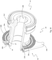
- FIG 2 a shows a perspective view of the known rear derailleur 10 according to DE'253.
- the rear derailleur 10 is mounted coaxially on the rear wheel axle 6.
- the rear wheel hub 3 arranged between the two dropouts of the rear frame 1 and the derailleur 10 encompassing the right dropout can be seen.
- the base element 20 is mounted coaxially with the axis A on the rear frame 1 by means of the adapter 60.
- Figure 2 b) shows a section along the axis A of the figure Fig. 2 a) shown rear derailleur 10 in the rear view.
- the geometric axis A extends along the rear wheel axle 6.
- the base element 20 is attached to the right dropout by means of the adapter 60. To do this, the adapter 60 reaches through the right frame opening 2b.
- the thru axle 7 is inserted into the left frame opening 2a and screwed to the adapter 60.
- the adapter 60 also serves as a counter for the thru axle 7. When the thru axle 7 is tightened, it screws further into the adapter 60 and clamps itself opposite the rear triangle 1.
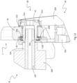
- Figure 3 a shows a perspective partial section of the base element 20 mounted on the rear frame 1 with the aid of the adapter 60 and parts of the hub arrangement.
- the first arm 22a and the second arm 22b are each positioned on one side of the rear frame 1.
- the hub arrangement (only a hollow axle or hub axle 5 is shown here) and a hub end cap 4 along a hub guide 27 on the inside of the base element 20.
- the hub guide 27 is designed as a collar with converging guide surfaces.
- the hub end cap 4 lies in its final position radially on the Hub guide 27. In the axial direction, the hub end cap 4 abuts against an axial hub stop surface 26 on the inside of the base element 20.
- the hub end cap 4 is shown in section.
- Figure 3 b shows an enlarged partial section of the base element 20 mounted with the adapter 60 on the rear frame 1.
- the adapter 60 is also shown in section.
- the bolt head 62 and the nut 66 are larger than the frame opening 2b.
- the nut 66 has a Fig.6 DE'253 has a knurled surface 69 in order to create a particularly strong frictional connection and, depending on the design and material of the dropouts in the area where the nut is to be mounted, an additional positive connection to the rear frame 1 and to counteract the forward rotation of the rear derailleur 10 (counterclockwise).
- the bolt body 63 has a contact area 63a that rests against the frame opening 2b with little play and a compensation area 63b that has more play compared to the frame opening 2b.
- the compensation area 63b enables the adapter 60 to align itself in the frame opening 2b along the axis A.
- the bolt 61 has play in the frame opening 2b and can tilt slightly in it if the frame opening is not exactly aligned with the axis A.
- Fig.4 was compared to the original Fig.8 DE'253 is supplemented by a double arrow and a reference symbol D associated therewith, which indicates an effective support radius and thus an effective support diameter, for the mutually interacting stop surfaces 68a and 68b of the adapter nut 66 on the one hand and the stop surfaces 24a and 24b of the base element 20 formed by pins or bolts of the inner arm 22a of the base element 20 projecting axially from the inside, which come into contact with one another.
- the adapter 60 has two functions: 1) The clamping on the rear frame 1 is produced by the screw connection between bolt 61 and nut 66. It is important that the adapter 60 can be fixed relative to the frame 1 and can be adjusted to it in the axial direction. For example, with a thinner frame eye 1b, the screw connection can be tightened further than with a thicker frame eye 1b. 2) The adapter 60 can only be rotated clockwise relative to the base element 20 to a limited extent and thus represents an anti-twisting device and a forward stop. For this purpose, two stops 68a, 68b are arranged on the nut 66, which interact with two pins 24a, 24b on the base element 20, see. Fig. 3 b) .
- a rotation of the rear derailleur 10 forwards (anti-clockwise) is only possible to a limited extent due to the anti-twist device between the adapter 60 and the base element 20.
- the anti-twist device replaces the usual B screw and protects against an unintentional rotation of the rear derailleur.
- the pivoting position of the base element 20 on the rear frame 1, defined by the stop of the pins 24a, 24b on the stops 68a, 68b results in a corresponding tension of the chain guided by the chain guide arrangement 50 and a corresponding distance of the top chain guide roller from a reference pinion of the pinion set (so-called "chain gap").
- the invention described here now relates primarily to aspects of the adapter and its interfaces to the rear frame and base element 20, which is also referred to in the industry as B-knuckle, cf. Figures 1 to 10 in the DE'253.
- a first subject of the invention it is about ensuring the required adjustability of a base element 20 of the rear derailleur on the bicycle frame by means of the adapter during assembly, and for this purpose, among other things, a secure attachment of one or more stop surfaces 168 of the nut or adapter nut 66 (cf. the stops 68a, 68b of the adapter nut 66 according to DE'253) to one or more stop surfaces 124 of the base element 20 (cf. the stop surfaces 24a, 24b of the base element 20 according to DE'253).
- stop surfaces of the nut or adapter nut 66 and stop surfaces of the base element 20 this should also include the possibility that the adapter nut 66 only has a corresponding stop surface and that the base element has only one corresponding stop surface, unless the respective context clearly indicates a plurality of stop surfaces of the base element and/or the adapter nut.
- the invention provides several complementary concrete solutions to these problems, some of which can also be viewed as alternative solutions. However, all of these solutions can also be implemented together.
- the knurled surface of the adapter nut is prevented from contacting its associated contact surface on the frame eye before the stop position of the stop surfaces 168 and 124 (cf. 68a, 68b, 24a, 24b according to DE'253) of the adapter nut and the base element 20 is reached.
- the driving torque between the adapter bolt and the adapter nut is increased.
- the holding torque between the adapter nut 66 and the base element which is undesirable during the derailleur assembly or adjustment because it prevents the rotation of the adapter nut until it reaches its correct rotation and stop position on the base element 20, is reduced.
- One embodiment of the invention provides for a spring element to be integrated preferably in a groove in the adapter nut.
- the groove is preferably provided in the area of the knurled surface 69 or contact surface of the adapter nut towards the contact surface of the frame eye, which is suitable for receiving a corresponding, preferably axially acting spring element.
- the spring element according to the embodiment shown in the figures discussed in more detail below projects in the axial direction beyond the knurled surface of the adapter nut in such a way that when the adapter bolt is tightened, the spring element contacts the contact surface of the frame eye before the knurled surface of the adapter nut can touch the contact surface of the frame eye.
- the spring element is initially partially pre-tensioned when the adapter bolt is tightened until the knurling of the adapter nut can grip the contact surface of the frame eye. If the bolt is tightened during the assembly or adjustment process of the derailleur, the spring initially ensures an air gap between the contact surface of the frame eye and the knurling surface. As the adapter bolt is tightened further, the spring element is further pre-tensioned and the air gap is gradually reduced. As the pre-tension of the spring element increases, the axial clamping force generated by the adapter bolt and adapter nut increases. whereby the driving torque from the adapter bolt to the adapter nut also increases due to increasing friction in the thread.
- a frictional engagement element can be provided which is effective between the adapter bolt 61 and the adapter nut 66 and functions, for example, according to the principle of a self-locking nut in order to ensure that the adapter nut rotates when the adapter bolt is turned.
- the spring element or the frictional engagement driving element is provided, or if the spring element and the frictional engagement driving element are both provided, then there is generally sufficient driving torque available on the adapter nut 66 to safely reach the rotation stop between the stop surfaces or stop elements 168 and 124 (cf. 68a, 68b, 24a, 24b according to DE'253) of the adapter nut and base element 20 before the knurling of the adapter nut engages the contact surface of the frame eye.
- the adapter nut can still be designed with a groove suitable for receiving the spring element, for example in order to reduce the variety of parts when embodiments with the spring element and Embodiments are to be produced without the spring element or to create an easy possibility for retrofitting the spring element if necessary.
- a radial groove in the adapter nut in the overlap area of the adapter nut with the left arm of the base element can serve as a holder for a ring element.
- This ring element serves as a plain bearing to ensure a low holding torque between the adapter nut and the base element when tightening the adapter bolt, and is made of a suitable plain bearing material (e.g. POM).
- the ring element is dimensionally designed such that its outer diameter forms a press fit with the inner diameter of the base element in the overlap area between the ring element and the left arm of the base element.
- the inner diameter of the ring element in turn has a clearance fit with the outer diameter of the adapter nut in the groove area.
- An inverse assignment of the inner diameter and the outer diameter to a press fit and a clearance fit of the ring element is also possible.
- the radial groove could alternatively also be designed in the left (inner) arm of the base element.
- the ring element acts as a sliding bearing for the adapter nut in the base element, while also providing axial fixation of the Adapter nut is implemented in the base element.
- This integration simplifies the assembly process and prevents the adapter nut from getting lost when the derailleur is dismantled.
- the axial play i.e. the axial gap in the radial groove between one end of the radial groove of the adapter nut and an engagement projection on the ring element with which the latter engages in the radial groove of the adapter nut, is designed such that this axial gap closes when the bolt is tightened before the knurled surface of the adapter nut engages its contact surface on the frame eye.
- a second invention topic is about achieving a high holding torque between the adapter nut and the frame eye.
- the adapter nut and adapter bolt When assembled, the adapter nut and adapter bolt are firmly clamped to the frame eye by their axial thread forces. During operation, considerable forces are transferred from the base element to the nut via the rotation stop of the stop surfaces 168 of the adapter nut 66 and the stop surfaces 124 of the base element and from there are further diverted into the rear frame.
- the angle position of the adapter nut in relation to the frame eyelet must not be adjusted during the adjustment process in order to ensure correct operation of the rear derailleur. It has been shown that a high holding torque between the nut and the frame eyelet is of great importance.
- the invention proposes that an outer flange is provided on the adapter nut 66.
- This flange is designed in such a way that it extends into a gap area provided for this purpose between the inner arm of the base element and the frame eye.
- the determined knurling surface is then applied to the radially outer area of the available contact surface in order to use the maximum effective diameter for the holding torque.
- the invention is suitable for equipping lightweight frames made of composite materials with coaxial derailleurs, while still ensuring error-free operation even in extreme terrain.
- a third invention topic is about achieving a high holding torque between the nut and the base element in the stop direction.
- the invention solves this problem by significantly increasing the support diameter effective for this force or torque transmission from the base element 20 of the derailleur to the adapter nut 66 and from there via the knurled surface of the adapter nut to the frame eye and thus the frame rear structure compared to the prior art, e.g. according to DE'253.
- the flange area of the adapter nut is used for this purpose or extended radially outwards beyond the knurled surface of the adapter nut.
- the counter stop 124 is attached to the base element 20 in the front area of the support structure on the inner arm.
- the frame interface offers additional space in this area, which can be used for mounting adapters for non-coaxial derailleurs, such as those from the EN 10 2018 206 104 A1 (DE'104) and the EN 10 2018 222 834 A1 (DE'834).
- This installation space is used on the one hand to position the contact surface or the stop element 124 as far radially outward as possible.
- this flange area of the adapter nut is designed in such a way that only a limited angle range is available up to the possible stop of the flange area of the adapter nut on the front stop of the frame interface. This front stop on the frame can therefore be used to provide a holding force for the adapter nut when loosening the bolt, e.g. to dismantle the rear derailleur.
- the angular range up to the stop of the flange area of the adapter nut at the front stop of the frame interface can be made significantly smaller, since this angular range in the arrangement according to the present invention is not related to the pivoting range of the rear derailleur.
- the reduced angle range reduces the abrasion on the contact surface of the frame eye for the adapter nut, which can occur when the adapter nut turns when the adapter bolt is loosened due to the knurling of the adapter nut.
- only a small, limited angle range has to be overcome during the adjustment process of the derailleur, which contributes to the quick and safe reaching of the correct stop position of the flange area of the adapter nut on the stop element 124 of the derailleur base element.
- a fourth invention topic concerns alternative designs of the adapter nut.
- the stop nut can advantageously be designed with a second stop, as an alternative to the adapter nut being designed with only a first stop.
- an adapter nut with either one or two stop areas.
- These adapter nuts can be easily exchanged for each other, and the rear derailleur can thus be optimized for the respective application.
- an adapter nut with a stop area is not only the weight saving but above all the large swivel range of the rear derailleur. This makes it easier to remove the wheel and can even be done if the rear derailleur is positioned under one of the larger pinions of the pinion cassette. In the event of defects during racing, this functionality can save valuable seconds.
- the adapter nut design with two stop areas limits the rear derailleur's swivel range. This means that the wheel can usually only be removed quickly if the derailleur is positioned in the area of the smaller pinions of the pinion cassette.
- limiting the swivel range to the rear helps to avoid damage that can be caused by the derailleur being forcibly swung back. Such situations can occur if the chain is blocked in the derailleur cage, e.g. by a foreign object getting jammed. If you continue pedaling, the chain force will then swing the derailleur backwards. This is also particularly important for Pedelecs or e-bikes, where the drive force can be particularly high, or where the motor control often does not detect a foreign object getting jammed in the derailleur in time, which can lead to the derailleur breaking off.
- a fifth invention topic is the easy detection of a misalignment of the derailleur on the frame eyelet and an aid for (re)adjusting the position of the derailleur correctly.
- the invention provides a so-called “crash indicator” (also known as a "B-gap control indicator”).
- the components in the derailleur arrangement known from DE'253 are designed in such a way that a correspondingly relatively high force is required to overcome this frictional connection in order to ensure the correct positioning of the derailleur during normal operation.
- the rear derailleur in order to restore the correct positioning of the rear derailleur after such events, the rear derailleur must be manually brought into the original stop position between the stop surfaces 168 and 124 (cf. 68a, 68b, 24a, 24b according to DE'253) of the adapter nut 66 and the base element 20.
- the invention solves both of these problems with a control display that is preferably clearly visible to the user, for example with two display elements, one preferably on the base element and the other preferably on the adapter nut.
- the control display visualizes the correct positioning of the stop element 124 of the base element on the associated front stop 168 of the adapter nut 66, and thus the correct swivel angle position of the derailleur, in particular with regard to chain tension and chain gap.
- the derailleur If the derailleur is deflected backwards, a visible distance is created between the display element on the base element and the display element on the adapter nut, which is fixed to the frame. This distance indicates that manual repositioning of the derailleur is necessary and can also give the user information about the impact energy absorbed by the derailleur. This allows the user to classify the collision event and, if necessary, decide on further functional checks or maintenance measures.
- the rear derailleur is pivoted forward until the stop position between the stop surfaces or stop elements 168 and 124 of the adapter nut 66 and the base element 20 is reached again, and thus the display elements are also aligned again.
- This adjustment process thus adds a visual check to the haptic check (resistance caused by the stop surfaces or stop elements 168 and 124 coming into contact with one another). In practice, this redundancy is perceived positively by the user.
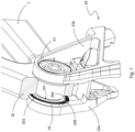
- Fig.5 shows in the partial figure 5 a) a sectional view of the right side of the rear frame 1 of the bicycle frame F together with the base element 20 with its inner or left arm 22a and its right or outer arm 22b.
- the base element is attached to the frame eye 1b of the rear frame 1 by means of an adapter 60, analogous to the known solution of DE '253.
- the adapter has the known adapter bolt 61 and the known adapter nut 66, which are in mutual locking engagement.
- the adapter nut 66 is designed with an outer flange 202. All components shown are shown in section.
- the rear frame 1 is designed in its area 1b, which can also be referred to as a dropout instead of a frame eye and can be seen in the figures, with a right frame opening 2b, which can be understood as a frame eye in the narrower sense and into which the adapter bolt 61 is inserted.
- a right frame opening 2b which can be understood as a frame eye in the narrower sense and into which the adapter bolt 61 is inserted.
- the entire dropout including a frame area surrounding the frame opening 2b, is referred to as the frame eyelet.
- the adapter nut 66 has a groove 204 on an axial inner side facing the rear frame 1 in the radial area of the outer flange 202, in which a spring element 206 is accommodated.
- the spring element is only designated with the reference number 206 in the partial figure 5 b).
- the outer flange 202 has an annular knurled surface 208 on its surface facing the frame eye.
- the spring element 206 which is preferably designed as a steel spring, projects axially out of the spring groove 204, i.e. in front of the knurled surface 208.
- the spring element 206 ensures, through its corresponding pre-tension in this axially protruding position, that in a pre-assembled state as in Fig.5 shown in which the adapter bolt 61 is not yet tightened, the knurled surface 208 is kept at a distance from the associated contact surface of the frame eye 1b, so that an axial air gap 210 is maintained between the frame eye and the knurled surface of the nut before the adapter bolt is tightened. A premature frictional or even positive grip of the knurled surface 208 on the frame eye is thus prevented.
- the maximum friction between the spring element 206 and the inside of the dropout then acts at this point. This ensures that the correct or desired angular position of the base element 20 can be set by appropriately turning the adapter bolt 61 in its tightening direction.
- Bearing elements can be assigned to the frame opening 2b, the adapter bolt 61 and the upper area of the second arm 22b, for example an axially effective bearing collar 212, a radially and axially effective bearing bush 214 and a radially effective bearing bush 216.
- These bearing elements can be made from a stiff and resilient plain bearing material and are mainly used to compensate for tolerances between the components involved that move against each other and to reduce the play between the adapter bolt and the frame eye or between the base element and the adapter bolt. This also ensures that the right derailleur arm 22b sits without play during the adjustment process. This protects sensitive frame surfaces and materials. However, such bearing elements can also be dispensed with.
- the embodiment shown is further characterized by a special ring element 218, which is arranged in an axial and radial intermediate region between the adapter nut 66 and the inner arm 22a of the base element, namely between mutually facing axial surfaces of the Inner arm 22a and the adapter nut 66 and an outer peripheral surface of the adapter nut 66 and an inner peripheral surface of the inner arm 22a.
- the ring element 218 engages with a radially projecting annular collar section 221 (cf. Fig. 16 ) into a radial annular groove 220 of the adapter nut 66 in the overlap area of the adapter nut with the left arm 22a.
- This annular groove 220 serves as a receptacle for the ring element 218 in order to fix the adapter nut on the inner arm 22a and thus in the base element 20.
- the ring element 218 is connected at its outer circumference by means of a press fit 219 to an inner circumference of an axially projecting collar region 248 (cf. Fig. 16 ) of the inner arm 22a and has a clearance fit with the adapter nut 66 on its inner circumference.
- the ring element 218 can be made of a suitable plain bearing material and provides an axial sliding surface in the axial overlap area of the adapter nut with the left arm 22a of the base element 20.
- a plain bearing is provided which acts between the adapter nut 66 and the base element 20 in order to reduce the friction between these components. This means that a larger proportion of the rotational forces introduced into the adapter bolt 61 in the tightening direction, more precisely the forces exerted on the adapter nut 66 as a result of these forces, is available for adjusting the angular position of the base element 20 at the dropout.
- the arrangement is preferably such that in the last phase of tightening the bolt 61 in the adapter nut 66, when the spring element 206 is completely pushed into the spring groove 204 by the inner surface of the dropout 1b, the two ring collars abut one another and the ring element 218 is axially pulled out slightly from its press fit 219 with the inner arm 22a by the adapter nut 66, i.e. is carried along a certain axial distance by the adapter nut 66.
- the knurled surface 208 can only be provided outside the groove 204 that accommodates the spring element 206.
- An axial ring face of the adapter nut that is designed without knurling and is located radially inside the groove 120 is designated here with 209. This area of the adapter nut facing the frame eye can also be designed with knurling, as shown in the Figures 15 to 21 shown.
- the interface 125 between the base element 20 and the adapter nut 66 could be designed in order to enable a transmission of rotational adjustment forces from the adapter nut 66 to the base element 20 on the basis of rotational forces exerted on the adapter bolt 61 in the tightening direction.
- a particularly expedient design is shown in Fig.8
- the inner arm 22a of the base element is designed with an axially projecting projection, namely in the front region of a support structure on the inner arm, which provides a stop surface 124.
- the projection is formed by a preferably separate stop element, designed as a stop bolt, which is also designated 124 for the sake of simplicity.
- a radially projecting flange region 168 of the outer flange 202 of the adapter nut 66 is assigned to this stop surface 124 or this stop element 124, which forms the stop surface of the adapter nut assigned to the stop surface 124.
- the same reference numeral 168 is used for this flange region and the stop surface provided by it.
- the flange region 168 and the stop element 124 or the stop surfaces provided by them together form the mentioned interface 125 between the base element and the adapter nut, which in Fig.8 highlighted and identified by the dashed circle 125.
- the flange area 168 is preferably shaped in such a way that only a limited angle range ⁇ is available up to the stop at a limit of the frame interface. This limits in particular the wear and tear or damage to the frame surface caused by the knurled surfaces of the adapter nut in the event of any violent twisting of the derailleur forwards, and reduces this compared to the prior art.
- the mentioned preliminary estimate of the frame interface is in Fig.9 and is designated 230.
- This angular distance ⁇ is 8 degrees.
- Fig.9 is a representation corresponding to a view of the inside of the dropout 1b without the inner arm 22a of the base element held thereon, but with its stop element 124a and the ring element 218 press-fitted on the inner arm 22a.
- the frame-side contact surface for the adapter nut 66 on the frame eyelet 1b is designated 232.
- Fig.10 corresponds in the representation of the Fig.9 and shows a variant of the adapter nut 66.
- This has a second stop area, which is formed analogously to the stop 168 by a radially projecting section 240 of the outer flange 202 and serves to limit the pivoting range of the switching mechanism 10 to the rear.
- This stop 240 can also interact with the stop element 124 of the base element 20.
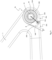
- FIGs 11 and 12 show again the adapter nut 66 of the Figure 5 to 9 in its position held on the inner arm 22a, namely in Fig. 11 in the stop engagement of its stop flange 168 on the stop element 124a of the base element 20 and in Fig. 12 in an assembly state in which this stop engagement between the stops 168 and 124 has not yet been established. Such a state can occur during the assembly of the base element on the rear frame 1.
- the stop flange 168 of the adapter nut 66 is first brought into contact with the stop element 124 of the base element 20, and then by further turning the adapter bolt 61 in the tightening direction by means of the adapter nut 66, adjusting torques can be exerted on the base element 20 in order to bring it into the desired angular position on the dropout 1b with the desired tension of the chain of the derailleur.
- Fig. 13 shows the base element 20 correctly and firmly mounted on the rear frame, more precisely the dropout or frame eye 1b, as it would be mounted coaxially to the rear wheel axle on the rear frame 1 as part of the complete derailleur with the associated pivot mechanism, the movable element and the chain guide.
- the inner arm 22a is then clamped between an inner side of the adapter nut 66 and a stator assembly of the rear wheel axle arrangement and is frictionally fixed in its angular position.
- a recognizable support structure of the base element is designated 234. It can be seen that the stop 124 of the inner arm 22a is formed by a separate stop bolt screwed into a screw opening of the inner arm. It can also be seen a Fig.5 visible hub guide 27 on the inside of the inner arm 22a of the base element 20.
- Fig. 13 thus shows the normal angular position or target angular position of the base element 20 relative to the adapter nut 66 and thus the frame eye 1b.
- the rear derailleur 10 is rotated backwards together with the adapter nut 66 until the chain slack disappears and after further tightening of the adapter bolt 61, while rotating the adapter nut 66 and the resulting rotation of the rear derailleur 10 in a clockwise direction, the desired chain gap or that provided by the manufacturer is achieved.
- the base element assumes this normal position or target position can be recognized very easily by a visual and/or haptic marking 241 on the inner arm 22a of the base element and an associated visual and/or haptic marking 242 on the outer circumference of the outer flange 202 of the adapter nut 66, which in the illustration according to Fig.13 axially aligned.
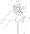
- Fig. 14 shows the base element in a position that has been pivoted out of its nominal or normal position while absorbing frictional energy, for example as a result of a fall, i.e. in a "crashed position" so to speak.
- the base element 20 is opposite the position according to Fig. 13 pivoted backwards. This results in the marking 241 on the inner arm 22a being pivoted forwards relative to the marking 242 on the outer circumference of the outer flange 22 of the adapter nut 66. Due to the frictional fixation of the adapter nut 66 on the frame eye 1b, the angular position of the adapter nut 66 continues to correspond to its previously set normal position or target position.
- a cyclist who has suffered a crash can now simply reset the target position of the base element 20 on the frame eyelet by loosening the quick release axle 7 screwed into the adapter bolt 61 and thus clamping the inner arm 22a in conjunction with the stator arrangement of the rear axle arrangement, then returning the base element to the pivot position according to Fig. 13 and then retightening the quick release axle, thereby restoring the axial clamping of the inner arm 22a.
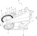
- Fig. 15 shows an exploded view of the base element 20 with the associated components described in detail above.
- a variant with a slightly different adapter nut 66 is shown. Instead of the ring surface 209 without knurling radially within the spring groove 204, this inner ring area of the contact surface of the adapter nut 66 facing the frame eye 1b is now also knurled.
- the shape of the spring element 206 can also be seen, which is designed as a substantially ring-shaped spring element with an axial corrugation and a gap between two spring ends facing each other. Accordingly, the spring groove 204 can also be designed as a circular arc segment adapted to this, i.e. with a knurled gap between two adjacent groove ends. However, it is also possible to design the spring groove 204 as an annular groove.
- Fig. 16 shows the components of the Fig. 15 in a sectioned exploded view including the dropout or the frame eye 1b.
- the groove 220 of the adapter nut 66 for the ring element 218 (or the ring-shaped sliding element 218) can be clearly seen.
- an annular engagement collar or engagement projection 221 on the inner circumference of the ring element 218 can be clearly seen.
- the axially projecting collar area 248 of the inner arm 22a is, as in connection with Fig.5 explained, is assigned to the radial groove 220 of the adapter nut 66 in the overlap region of the adapter nut with the left arm 22a and forms therewith an axial overlap region of the adapter nut with the left arm of the base element.
- Fig. 17 shows the adapter nut 66, which essentially corresponds to the adapter nut 66 of the first embodiment according to Fig.10 , i.e. has two stop outer flange areas 168 and 240. Deviating from this, the contact surface area is also knurled radially within the spring groove 204, as in the design variant of the Fig. 15 and 16 .
- the second embodiment is distinguished from the first embodiment in that the spring element 206 serving as a spacer element 206 is preferably omitted, so that the spring groove 204 on the contact surface of the adapter nut 66 could also be omitted.
- the spring groove 204 can still be provided in order to reduce the number of parts if an embodiment with the spring element 206 and an embodiment without the spring element 206 are to be provided.
- the existing spring groove 204 offers the option of retrofitting the spring element, should this prove to be expedient.
- the Figures 17 to 21 disclose both an embodiment with the spring element 206 and an embodiment without the spring element 206.
- the former embodiment is in Fig. 21 shown.
- a significant difference between the second embodiment and the first embodiment is a preferably annular engagement element 250, which provides a communicable frictional driving engagement between the adapter nut 66 and the adapter bolt 61 in order to be able to exert increased rotational forces on the adapter nut 66 on the basis of rotational forces introduced into the adapter bolt 61.
- Fig. 17 shows the engagement element 250 accommodated in an annular groove 252 of the adapter nut, which is arranged radially inside the annular groove 220 for the sliding element 218 and is open radially inward.
- This engagement element or engagement ring 250 can also be referred to as a clamping ring and is typically made of plastic, for example polyamide.
- the clamping ring 250 acts in the manner a corresponding clamping ring or clamping part of a self-locking nut or lock nut, which serves as a screw lock.
- Fig. 18 shows the adapter bolt 61 in its state screwed into the adapter nut 66. Also visible is a schematically shown external thread 64 of the adapter bolt, which extends from an annular groove 256 on the outer circumference of the adapter bolt to the inner end of the adapter bolt 61, as well as a schematically shown internal thread 67 of the adapter nut 66. This external thread and this internal thread are also shown in the partial figures of Fig.5 recognizable as schematically represented, but not explicitly shown in the other figures discussed above.
- the clamping ring 250 therefore ensures that increased rotational driving forces can be exerted on the adapter nut 66 by turning the adapter bolt 61 in the tightening direction (or of course alternatively in the opposite direction to the tightening direction) using a tool inserted into a tool engagement opening 258, so that the provision of the spring element 206 serving as a spacer element will generally be dispensable. It may also be possible to dispense with the sliding ring 218 between the adapter nut 66 and the inner arm 22a of the base element 20, as far as the aim is to exert sufficient rotational forces on the base element by means of the adapter bolt 61 and the adapter nut 66 for adjusting the chain tension.
- the embodiment of the Fig. 18 differs from the first embodiment also by a bearing ring 214' instead of the bearing bush 214.
- Fig. 19 shows the components of the Fig. 18 together with the base element 20 and an associated, essentially schematically shown rear wheel axle arrangement comprising a quick-release axle 7 screwed into the adapter bolt 61, which extends through an assembly H comprising stationary components 104, 107, 108 and rotary components 103, 200.
- Fig. 20 corresponds to this illustration.
- the left dropout 1a and the right dropout 1b or the left frame eye 1a and the right frame eye 1b of the rear triangle 1 of the bicycle frame F are shown.
- the spring element 206 is not provided.
- Fig. 21 shows, in an enlarged view, the design variant in which the spring element 206 and the clamping ring 250 are both present.
- a rear derailleur of a bicycle derailleur which is intended for coaxial mounting with respect to a rear wheel axle A on a support section 1b of a rear triangle 1 of a bicycle frame F of a bicycle using an adapter 60 comprising an adapter bolt 61 and an adapter nut 66 and has a two-armed base element 20, a pivot mechanism 30, a movable element 40, and a chain guide arrangement 50, is characterized according to one aspect of the invention by at least one engagement element 206 / 218 / 250 which mediates an indirect frictional engagement between the adapter nut 66 on the one hand and at least one of a) an inner first arm 22a of the base element 20, b) an axial inner side of the support section 1b and c) the adapter bolt 61 on the other hand, which engagement element 206 / 218 / 250 in a defined pre-assembled state in the sense of an enlargement of a by means of the adapter bolt 61 and the adapter nut 66 on the base element 20 exerted subsequent
Landscapes
- Engineering & Computer Science (AREA)
- Chemical & Material Sciences (AREA)
- Combustion & Propulsion (AREA)
- Transportation (AREA)
- Mechanical Engineering (AREA)
- Axle Suspensions And Sidecars For Cycles (AREA)
- Devices For Conveying Motion By Means Of Endless Flexible Members (AREA)
Claims (15)
- Dérailleur arrière (10) d'un changement de vitesses à dérailleur de bicyclette pour le montage coaxial, par rapport à un axe de roue arrière (A), sur un cadre structural arrière (1) d'une bicyclette, présentant :- un élément de base (20),- un mécanisme de pivotement (30),- un élément mobile (40), et- un ensemble de guidage de chaîne (50) ;le mécanisme de pivotement (30) reliant l'élément de base (20) à l'élément mobile (40), et l'ensemble de guidage de chaîne (50) précontraint ou pouvant être précontraint dans une direction de tension de chaîne par le biais d'un ensemble accumulateur de force étant relié à l'élément mobile (40) de manière à pouvoir tourner autour d'un axe de rotation (P) ;l'élément de base (20) comprenant une première extrémité de raccordement (21) pour le montage coaxial, par rapport à l'axe de roue arrière (A), sur le cadre structural arrière (1) et une deuxième extrémité de raccordement (29) pour l'accouplement au mécanisme de pivotement (30);la première extrémité de raccordement (21) présentant un premier bras (22a) et un deuxième bras (22b), qui sont disposés de manière espacée l'un de l'autre dans la direction axiale et sont conçus pour le montage du dérailleur (10) sur une partie de support (1b) associée du cadre structural arrière (1) au moyen d'un adaptateur (60) associé ;dans un état prémonté défini et dans un état complètement monté, le premier bras (22a) se trouvant sur un côté intérieur axial de la partie de support (1b) et le deuxième bras (22b) se trouvant sur un côté extérieur axial de la partie de support (1b) ;l'adaptateur comprenant un boulon d'adaptateur (61) et un écrou d'adaptateur (66) associé pouvant être vissé sur le boulon d'adaptateur (61) et, dans l'état prémonté défini et dans l'état complètement monté, une tête de boulon (62) du boulon d'adaptateur (61) étant disposée sur le côté extérieur axial de la partie de support (1b) et l'écrou d'adaptateur (66) se trouvant en prise par vissage avec le boulon d'adaptateur (61) étant disposé sur le côté intérieur axial de la partie de support (1b) ; etdans l'état prémonté défini, par rotation du boulon d'adaptateur (61) dans un sens de serrage à fond, une force de rotation pouvant être exercée sur l'écrou d'adaptateur (66), force sur la base de laquelle, par le biais d'au moins une formation d'entraînement de l'écrou d'adaptateur (66) et d'au moins une formation d'entraînement conjuguée associée de l'élément de base (20), une force de rotation subséquente peut être exercée sur l'élément de base (20) pouvant tourner par rapport à la partie de support (1b) dans l'état prémonté défini, dans un premier sens de rotation correspondant au sens de rotation de serrage à fond, laquelle force de rotation subséquente agit à l'encontre d'une force de rotation conjuguée exercée sur l'élément de base (20), laquelle force de rotation conjuguée est exercée sur l'élément de base (20) dans un deuxième sens opposé au premier sens de rotation par l'intermédiaire d'une chaîne de bicyclette, guidée par le biais de l'ensemble de guidage de chaîne (50), du changement de vitesses à dérailleur de bicyclette ;caractérisé par au moins un élément d'entrée en prise (206 ; 218 ; 250) transmettant une entrée en prise par friction directe entre l'écrou d'adaptateur (66) d'une part et au moins un parmi a) le premier bras (22a) de l'élément de base (20), b) le côté intérieur axial de la partie de support (1b) et c) le boulon d'adaptateur (61) d'autre part, lequel élément d'entrée en prise agit dans le sens d'une augmentation de la force de rotation subséquente pouvant être exercée sur l'élément de base.
- Dérailleur arrière selon la revendication 1, caractérisé par au moins un élément d'entrée en prise (250) réalisé et disposé pour la transmission d'une entrée en prise par friction directe entre l'écrou d'adaptateur (66) d'une part et le boulon d'adaptateur (61) d'autre part, lequel élément d'entrée en prise agit dans le sens d'une augmentation de la force de rotation pouvant être exercée sur l'écrou d'adaptateur dans l'état prémonté défini.
- Dérailleur arrière selon la revendication 1 ou 2, caractérisé par au moins un élément d'entrée en prise (206 ; 218) réalisé et disposé pour la transmission d'une entrée en prise par friction directe entre l'écrou d'adaptateur (66) d'une part et au moins un parmi a) le premier bras (22a) de l'élément de base (20) et b) le côté intérieur axial de la partie de support (1b) d'autre part, lequel élément d'entrée en prise, dans l'état prémonté défini, influence un rapport instantané entre une force de rotation d'origine exercée sur le boulon d'adaptateur (61) dans le sens de serrage à fond et faisant tourner celui-ci par rapport à la partie de support (1b) et la force de rotation subséquente résultante dans le sens d'une augmentation de la force de rotation résultante.
- Dérailleur arrière selon l'une des revendications 1 à 3, caractérisé par au moins un élément d'entrée en prise (250) réalisé pour la transmission d'une entrée en prise par friction directe, lequel élément d'entrée en prise, dans l'état prémonté défini, est serré entre l'écrou d'adaptateur (66) et le boulon d'adaptateur (61) et accouple par friction l'écrou d'adaptateur (66) au boulon d'adaptateur (61), afin de de fournir un entraînement en rotation à friction de l'écrou d'adaptateur (66) par le biais du boulon d'adaptateur (61) .
- Dérailleur arrière selon l'une des revendications 1 à 4, caractérisé par au moins un élément d'entrée en prise (218) réalisé pour la transmission d'une entrée en prise par friction directe, lequel élément d'entrée en prise, dans l'état prémonté défini, produit un palier lisse associé au premier bras (22a) de l'élément de base (20) et à l'écrou d'adaptateur (66), réduisant une friction survenant entre le premier bras (22a) de l'élément de base (20) et l'écrou d'adaptateur (66), afin de réduire des forces conjuguées s'opposant à une rotation de l'écrou d'adaptateur (66) dans le premier sens de rotation.
- Dérailleur arrière selon l'une des revendications 1 à 5, caractérisé par au moins un élément d'entrée en prise (206) réalisé pour la transmission d'une entrée en prise par friction directe et retenu sur l'écrou d'adaptateur (66) et servant d'élément d'espacement axial, lequel est associé à une/la surface d'appui, réalisée de préférence sous forme de surface moletée (208), de l'écrou d'adaptateur (66) et à une surface d'appui (232) sur le côté intérieur axial de la partie de support (1b) et, dans l'état prémonté défini, agit en tant qu'élément d'espacement actif entre celles-ci, lequel maintient de manière axialement espacée la surface d'appui de l'écrou d'adaptateur (66) et la surface d'appui (232) de la partie de support (1b) lors de la rotation du boulon d'adaptateur (61) dans le sens de rotation de serrage à fond sur une plage angulaire de rotation prévue du boulon d'adaptateur (61), avant que la surface d'appui de l'écrou d'adaptateur (66) ne vienne en prise par appui avec la surface d'appui (232) associée de la partie de support en cas de rotation supplémentaire du boulon d'adaptateur (61) dans le sens de rotation de serrage à fond.
- Dérailleur arrière selon l'une des revendications 1 à 6, caractérisé en ce qu'une partie de bride extérieure (168) de l'écrou d'adaptateur (66) forme la formation d'entraînement de l'écrou d'adaptateur (66) et une saillie (124) de l'élément de base (20), faisant saillie à partir d'un côté extérieur du premier bras (22a ; 22a' ; 22b") axialement en direction du deuxième bras (22b ; 22b"), éventuellement réalisée sous forme de boulon de butée séparé, forme la formation d'entraînement conjuguée.
- Dérailleur arrière selon l'une des revendications précédentes, caractérisé en ce que, dans l'état complètement monté, la tête de boulon (62) et l'écrou d'adaptateur (66) sont serrés sur la partie de support (1b) par des forces de filetage axiales ;l'écrou d'adaptateur (66), sur un côté axial tourné vers la partie de support (1b), étant doté d'une surface moletée (208) qui, dans l'état complètement monté, vient en prise avec une/la surface d'appui (232) associée sur le côté intérieur axial de la partie de support (1b) ; etl'écrou d'adaptateur (66) étant doté d'une bride extérieure (202) qui présente un moletage sur un côté axial tourné vers la partie de support (1b), lequel moletage forme la surface moletée (208) ou agrandit celle-ci dans la direction radiale, la bride extérieure s'étendant, dans l'état complètement monté, dans un espace axial entre le premier arbre (22a) de l'élément de base (20) et le côté intérieur axial de la partie de support (1b).
- Dérailleur arrière selon la revendication 8, caractérisé en ce que la bride extérieure est réalisée sous forme de bride annulaire s'étendant de manière annulaire autour d'une région centrale de l'écrou d'adaptateur (66) présentant une ouverture filetée pour le boulon d'adaptateur (61), laquelle bride annulaire présente, sur son côté axial tourné vers la partie de support (1b), un moletage s'étendant de manière annulaire.
- Dérailleur arrière selon la revendication 8 ou 9, caractérisé en ce que la bride extérieure (202) forme une butée avant (168) pour une butée conjuguée (124) associée de l'élément de base (20), afin de supporter, par complémentarité de forme, sur l'écrou d'adaptateur (66) serré fixement sur la partie de support (1b), des forces agissant sur l'élément de base (20) dans un sens vers l'avant dans l'état complètement monté.
- Dérailleur arrière selon l'une des revendications 8 à 10, caractérisé en ce que la bride extérieure (202) forme une butée arrière (240) pour une butée conjuguée (124) associée de l'élément de base (20), afin de limiter un angle de pivotement de l'élément de base (20) par rapport à la partie de support (1b) dans un sens vers l'arrière dans l'état prémonté défini où l'adaptateur (60) n'est pas encore serré fixement ou dans un état correspondant à l'état prémonté après le desserrage de l'adaptateur (60) préalablement serré fixement.
- Dérailleur arrière selon l'une des revendications précédentes, caractérisé en ce que l'élément de base (20) est serré axialement et fixé par friction de manière à empêcher une rotation dans l'état complètement monté sur une partie de serrage de son premier bras (22a) entre l'adaptateur (60) et un module de stator d'un ensemble d'axe de roue arrière associé à une roue mobile arrière de la bicyclette, un affichage de contrôle (241, 242) étant prévu, lequel permet d'identifier au moins un positionnement parmi un positionnement angulaire de consigne, existant momentanément, de l'élément de base (20) et un positionnement angulaire erroné, existant momentanément, différant du positionnement angulaire de consigne, par rapport à au moins un élément parmi l'écrou d'adaptateur (66), la partie de support (1b) et le module de stator.
- Dérailleur arrière selon la revendication 12, caractérisé en ce que l'affichage de contrôle présente un premier élément d'affichage (241) sur un composant séparé se trouvant dans une relation angulaire relative fixe par rapport à l'élément de base (20), ou, de préférence, sur l'élément de base (20).
- Dérailleur arrière selon la revendication 12 ou 13, caractérisé en ce que l'affichage de contrôle présente un deuxième élément d'affichage (242) sur un élément parmi l'écrou d'adaptateur (66), la partie de support (1b) et le module de stator ou sur un composant se trouvant dans une relation angulaire relative fixe par rapport à un élément parmi l'écrou d'adaptateur (66), la partie de support (1b) et le module de stator.
- Bicyclette, comprenant un cadre de bicyclette (F) comportant une roue mobile arrière et un changement de vitesses à dérailleur présentant un dérailleur arrière (10) ;la bicyclette présentant en outre les caractéristiques suivantes :- la roue mobile arrière est dotée d'un ensemble de stator (104, 107, 108) comprenant un ensemble d'axe de roue arrière (104, 107, 108) et d'un ensemble de rotor (103, 200), l'ensemble de rotor étant monté de manière rotative par rapport à l'ensemble de stator et comprenant un moyeu de roue mobile (103) comportant un dispositif d'entraînement (200) supportant un groupe de pignons (R) du changement de vitesse à dérailleur ;- un cadre structural arrière (1) du cadre de bicyclette (F) présente une partie de support gauche et une partie de support droite (1b) pour un axe intérieur (107) de l'ensemble d'axe de roue arrière de la roue mobile arrière, lesquelles présentent une distance axiale définie prédéterminée le long d'un axe géométrique (A) de l'axe intérieur monté sur le cadre structural arrière (1) au moyen des parties de support et forment respectivement un appui conjugué pour un groupe de composants (4, 5, 8) disposé sur l'axe intérieur, serré entre les parties de support et comprenant un module de l'ensemble de stator ;- le dérailleur arrière (10, RD) est monté sur le cadre structural arrière (1) de manière coaxiale par rapport à l'axe géométrique (A) et comprend :- un élément de base (20),- un mécanisme de pivotement (30),- un élément mobile (40), et- un ensemble de guidage de chaîne (50) ;le mécanisme de pivotement (30) reliant l'élément de base (20) à l'élément mobile (40), et l'ensemble de guidage de chaîne (50) précontraint ou pouvant être précontraint dans une direction de tension de chaîne par le biais d'un ensemble accumulateur de force étant relié à l'élément mobile (40) de manière à pouvoir tourner autour d'un axe de rotation (P) ;l'élément de base (20) comprenant une première extrémité de raccordement (21) pour le montage coaxial, par rapport à l'axe géométrique (A), sur le cadre structural arrière (1) et une deuxième extrémité de raccordement (29) pour l'accouplement au mécanisme de pivotement (30) ;la première extrémité de raccordement (21) présentant un premier bras (22a) et un deuxième bras (22b), qui sont disposés de manière espacée l'un de l'autre dans la direction axiale et sont conçus pour le montage du dérailleur (10) sur la partie de support droite (1b) associée du cadre structural arrière (1) au moyen d'un adaptateur (60) associé ; l'adaptateur comprenant un boulon d'adaptateur (61) et un écrou d'adaptateur (66) associé pouvant être vissé sur le boulon d'adaptateur (61) ;le premier bras (22a) se trouvant sur un côté intérieur axial de la partie de support (1b) associée et le deuxième bras (22b ; 22b') se trouvant sur un côté extérieur axial de la partie de support (1b) ;une tête de boulon (62) du boulon d'adaptateur (61) étant disposée sur le côté extérieur axial de la partie de support (1b) et l'écrou d'adaptateur (66) se trouvant en prise par vissage avec le boulon d'adaptateur (61) étant disposé sur le côté intérieur axial de la partie de support (1b) ;caractérisé en ce que le dérailleur arrière (10) est réalisé selon l'une des revendications précédentes et est monté complètement sur le cadre structural arrière (1).
Applications Claiming Priority (3)
| Application Number | Priority Date | Filing Date | Title |
|---|---|---|---|
| DE102020007377 | 2020-12-03 | ||
| DE102021003319 | 2021-06-29 | ||
| DE102021131414.3A DE102021131414A1 (de) | 2020-12-03 | 2021-11-30 | Hinteres Schaltwerk zur koaxialen Anbindung an einem Fahrrad-Rahmen |
Publications (2)
| Publication Number | Publication Date |
|---|---|
| EP4008622A1 EP4008622A1 (fr) | 2022-06-08 |
| EP4008622B1 true EP4008622B1 (fr) | 2024-09-04 |
Family
ID=79730651
Family Applications (1)
| Application Number | Title | Priority Date | Filing Date |
|---|---|---|---|
| EP21401052.2A Active EP4008622B1 (fr) | 2020-12-03 | 2021-12-02 | Mécanisme de commutation arrière destiné à la liaison coaxiale à un cadre de bicyclette |
Country Status (4)
| Country | Link |
|---|---|
| US (1) | US12221191B2 (fr) |
| EP (1) | EP4008622B1 (fr) |
| CN (1) | CN217198524U (fr) |
| TW (1) | TW202225027A (fr) |
Families Citing this family (9)
| Publication number | Priority date | Publication date | Assignee | Title |
|---|---|---|---|---|
| DE102020201229A1 (de) * | 2019-03-22 | 2020-09-24 | Sram Deutschland Gmbh | Koaxiale Schaltwerksanbindung |
| DE102020132208A1 (de) * | 2019-12-18 | 2021-06-24 | Sram Deutschland Gmbh | Fahrrad-Schaltwerk und Anbindung eines Schaltwerks an einem Fahrrad-Rahmen |
| EP3838731B1 (fr) * | 2019-12-18 | 2024-05-15 | SRAM Deutschland GmbH | Dérailleur de bicyclette et raccordement d'un dérailleur à un cadre de bicyclette |
| TWI742700B (zh) * | 2020-05-29 | 2021-10-11 | 彥豪金屬工業股份有限公司 | 自行車後變速器 |
| EP3964437B1 (fr) * | 2020-09-03 | 2024-12-18 | SRAM Deutschland GmbH | Dérailleur arrière électromécanique pour montage coaxial pourvu de dispositif de blocage |
| TWI867135B (zh) * | 2020-12-31 | 2024-12-21 | 日商島野股份有限公司 | 托架裝置 |
| TWI800929B (zh) * | 2021-09-27 | 2023-05-01 | 彥豪金屬工業股份有限公司 | 自行車後變速器 |
| USD1044607S1 (en) * | 2023-01-04 | 2024-10-01 | Geo Handguards Llc | Rear bicycle derailleur |
| USD1083688S1 (en) * | 2025-01-10 | 2025-07-15 | Shenzhen yingfeinuo technology co., LTD | Bicycle |
Family Cites Families (14)
| Publication number | Priority date | Publication date | Assignee | Title |
|---|---|---|---|---|
| US8777788B2 (en) * | 2007-02-08 | 2014-07-15 | Shimano Inc. | Bicycle component positioning device |
| JP6146204B2 (ja) * | 2013-08-26 | 2017-06-14 | 株式会社ジェイテクト | 電動パワーステアリング装置 |
| DE102018001253A1 (de) * | 2017-03-20 | 2018-09-20 | Sram Deutschland Gmbh | Hinteres Schaltwerk zur koaxialen Montage |
| US10981626B2 (en) * | 2018-03-20 | 2021-04-20 | Sram Deutschland Gmbh | Drive arrangement for a bicycle |
| TWM562816U (zh) * | 2018-04-03 | 2018-07-01 | 彥豪金屬工業股份有限公司 | 變速器總成 |
| DE102018206104A1 (de) | 2018-04-20 | 2019-10-24 | Sram Deutschland Gmbh | Schaltauge zur Montage eines hinteren Schaltwerks an einem Fahrradrahmen und Set von Komponenten zur wahlweisen Montage alternativer hinterer Schaltwerke an dem Fahrradrahmen |
| DE102018214218A1 (de) * | 2018-08-22 | 2020-02-27 | Sram Deutschland Gmbh | Hinterrad-Kettenschaltwerk mit exzentrischer Seilzug-Umlenkrollenanordung mit Übersetzungsverhältnis |
| DE102018222834A1 (de) | 2018-12-21 | 2020-06-25 | Sram Deutschland Gmbh | Halterungselement und Fahrrad mit einem Halterungselement |
| EP3712052B1 (fr) | 2019-03-22 | 2026-04-08 | SRAM Deutschland GmbH | Raccordement coaxial de monte-et-baisse |
| DE102020201229A1 (de) | 2019-03-22 | 2020-09-24 | Sram Deutschland Gmbh | Koaxiale Schaltwerksanbindung |
| DE102020210354A1 (de) | 2019-08-23 | 2021-02-25 | Sram Deutschland Gmbh | Fahrradschaltwerk mit einstellanzeige |
| EP3782891B1 (fr) | 2019-08-23 | 2022-12-07 | SRAM Deutschland GmbH | Dérailleur de bicyclette pourvu d'affichage de réglage |
| DE102020132208A1 (de) | 2019-12-18 | 2021-06-24 | Sram Deutschland Gmbh | Fahrrad-Schaltwerk und Anbindung eines Schaltwerks an einem Fahrrad-Rahmen |
| EP3838731B1 (fr) | 2019-12-18 | 2024-05-15 | SRAM Deutschland GmbH | Dérailleur de bicyclette et raccordement d'un dérailleur à un cadre de bicyclette |
-
2021
- 2021-12-02 US US17/540,507 patent/US12221191B2/en active Active
- 2021-12-02 EP EP21401052.2A patent/EP4008622B1/fr active Active
- 2021-12-03 TW TW110145332A patent/TW202225027A/zh unknown
- 2021-12-03 CN CN202123025708.7U patent/CN217198524U/zh active Active
Also Published As
| Publication number | Publication date |
|---|---|
| US20220177075A1 (en) | 2022-06-09 |
| US12221191B2 (en) | 2025-02-11 |
| EP4008622A1 (fr) | 2022-06-08 |
| TW202225027A (zh) | 2022-07-01 |
| CN217198524U (zh) | 2022-08-16 |
Similar Documents
| Publication | Publication Date | Title |
|---|---|---|
| EP4008622B1 (fr) | Mécanisme de commutation arrière destiné à la liaison coaxiale à un cadre de bicyclette | |
| EP3556643B1 (fr) | Patte de dérailleur destiné au montage d'un mécanisme de commutation arrière à un cadre de bicyclette et ensemble de composants destiné au montage sélectif de mécanismes alternatifs de commutation arrière au cadre de bicyclette | |
| EP4063250B1 (fr) | Élément de retenue et bicyclette dotée d'un élément de retenue | |
| EP3388324B1 (fr) | Derailleur arrière destiné au montage coaxial | |
| DE102013001952B4 (de) | Hinterer Umwerfer mit Dämpferbaugruppe | |
| DE102014009070B4 (de) | Fahrradumwerfer | |
| DE102020201229A1 (de) | Koaxiale Schaltwerksanbindung | |
| DE102010010317B4 (de) | Fahrradrahmen mit gelenkiger Gestänge-Befestigungsanordnung | |
| DE69734618T2 (de) | Lärmdämpfungseinheit für Freilauf für ein Fahrrad | |
| DE60132539T2 (de) | Fahrradnabe mit Abstandshalter und lösbarem Freilauf | |
| DE60117331T2 (de) | Fahrradnabe mit Gewindeabstandshalter und lösbarem Freilauf | |
| DE102011103489B4 (de) | Hinterrad-Achsanordnung und hierfür ausgebildete Mehrfach-Ritzelanordnung | |
| EP3712052B1 (fr) | Raccordement coaxial de monte-et-baisse | |
| EP4393804A2 (fr) | Dérailleur de bicyclette et raccordement d'un dérailleur à un cadre de bicyclette | |
| EP2100806B1 (fr) | Composant de bicyclette | |
| EP3838731B1 (fr) | Dérailleur de bicyclette et raccordement d'un dérailleur à un cadre de bicyclette | |
| DE102007056966A1 (de) | Fahrrad-Kettenradbaugruppe | |
| DE102020209370A1 (de) | Fahrrad-Schaltwerk, insbesondere mit Feder-Dämpfer-Baugruppe | |
| DE202010013131U1 (de) | Fahrradkurbelanordnung | |
| DE102021124558A1 (de) | Fahrradpedal | |
| DE102020109601B4 (de) | Fahrzeugaufhängung | |
| DE102017006834A1 (de) | Schwenkbare Kettenblattanordnung | |
| EP3772453A1 (fr) | Mécanisme de monte-et-baisse de la bicyclette, en particulier pourvu de module ressort-amortisseur | |
| DE102017008543A1 (de) | Fahrradnabenanordnung | |
| DE102021131414A1 (de) | Hinteres Schaltwerk zur koaxialen Anbindung an einem Fahrrad-Rahmen |
Legal Events
| Date | Code | Title | Description |
|---|---|---|---|
| STAA | Information on the status of an ep patent application or granted ep patent |
Free format text: STATUS: UNKNOWN |
|
| PUAI | Public reference made under article 153(3) epc to a published international application that has entered the european phase |
Free format text: ORIGINAL CODE: 0009012 |
|
| STAA | Information on the status of an ep patent application or granted ep patent |
Free format text: STATUS: THE APPLICATION HAS BEEN PUBLISHED |
|
| AK | Designated contracting states |
Kind code of ref document: A1 Designated state(s): AL AT BE BG CH CY CZ DE DK EE ES FI FR GB GR HR HU IE IS IT LI LT LU LV MC MK MT NL NO PL PT RO RS SE SI SK SM TR |
|
| STAA | Information on the status of an ep patent application or granted ep patent |
Free format text: STATUS: REQUEST FOR EXAMINATION WAS MADE |
|
| 17P | Request for examination filed |
Effective date: 20221207 |
|
| GRAP | Despatch of communication of intention to grant a patent |
Free format text: ORIGINAL CODE: EPIDOSNIGR1 |
|
| STAA | Information on the status of an ep patent application or granted ep patent |
Free format text: STATUS: GRANT OF PATENT IS INTENDED |
|
| INTG | Intention to grant announced |
Effective date: 20240409 |
|
| GRAS | Grant fee paid |
Free format text: ORIGINAL CODE: EPIDOSNIGR3 |
|
| GRAA | (expected) grant |
Free format text: ORIGINAL CODE: 0009210 |
|
| STAA | Information on the status of an ep patent application or granted ep patent |
Free format text: STATUS: THE PATENT HAS BEEN GRANTED |
|
| AK | Designated contracting states |
Kind code of ref document: B1 Designated state(s): AL AT BE BG CH CY CZ DE DK EE ES FI FR GB GR HR HU IE IS IT LI LT LU LV MC MK MT NL NO PL PT RO RS SE SI SK SM TR |
|
| REG | Reference to a national code |
Ref country code: GB Ref legal event code: FG4D Free format text: NOT ENGLISH |
|
| REG | Reference to a national code |
Ref country code: CH Ref legal event code: EP |
|
| REG | Reference to a national code |
Ref country code: IE Ref legal event code: FG4D Free format text: LANGUAGE OF EP DOCUMENT: GERMAN |
|
| REG | Reference to a national code |
Ref country code: DE Ref legal event code: R096 Ref document number: 502021005041 Country of ref document: DE |
|
| P01 | Opt-out of the competence of the unified patent court (upc) registered |
Free format text: CASE NUMBER: APP_48394/2024 Effective date: 20240822 |
|
| REG | Reference to a national code |
Ref country code: LT Ref legal event code: MG9D |
|
| REG | Reference to a national code |
Ref country code: NL Ref legal event code: MP Effective date: 20240904 |
|
| PG25 | Lapsed in a contracting state [announced via postgrant information from national office to epo] |
Ref country code: NO Free format text: LAPSE BECAUSE OF FAILURE TO SUBMIT A TRANSLATION OF THE DESCRIPTION OR TO PAY THE FEE WITHIN THE PRESCRIBED TIME-LIMIT Effective date: 20241204 |
|
| PG25 | Lapsed in a contracting state [announced via postgrant information from national office to epo] |
Ref country code: GR Free format text: LAPSE BECAUSE OF FAILURE TO SUBMIT A TRANSLATION OF THE DESCRIPTION OR TO PAY THE FEE WITHIN THE PRESCRIBED TIME-LIMIT Effective date: 20241205 Ref country code: PL Free format text: LAPSE BECAUSE OF FAILURE TO SUBMIT A TRANSLATION OF THE DESCRIPTION OR TO PAY THE FEE WITHIN THE PRESCRIBED TIME-LIMIT Effective date: 20240904 Ref country code: FI Free format text: LAPSE BECAUSE OF FAILURE TO SUBMIT A TRANSLATION OF THE DESCRIPTION OR TO PAY THE FEE WITHIN THE PRESCRIBED TIME-LIMIT Effective date: 20240904 |
|
| PG25 | Lapsed in a contracting state [announced via postgrant information from national office to epo] |
Ref country code: BG Free format text: LAPSE BECAUSE OF FAILURE TO SUBMIT A TRANSLATION OF THE DESCRIPTION OR TO PAY THE FEE WITHIN THE PRESCRIBED TIME-LIMIT Effective date: 20240904 |
|
| PG25 | Lapsed in a contracting state [announced via postgrant information from national office to epo] |
Ref country code: LV Free format text: LAPSE BECAUSE OF FAILURE TO SUBMIT A TRANSLATION OF THE DESCRIPTION OR TO PAY THE FEE WITHIN THE PRESCRIBED TIME-LIMIT Effective date: 20240904 |
|
| PG25 | Lapsed in a contracting state [announced via postgrant information from national office to epo] |
Ref country code: HR Free format text: LAPSE BECAUSE OF FAILURE TO SUBMIT A TRANSLATION OF THE DESCRIPTION OR TO PAY THE FEE WITHIN THE PRESCRIBED TIME-LIMIT Effective date: 20240904 |
|
| PG25 | Lapsed in a contracting state [announced via postgrant information from national office to epo] |
Ref country code: ES Free format text: LAPSE BECAUSE OF FAILURE TO SUBMIT A TRANSLATION OF THE DESCRIPTION OR TO PAY THE FEE WITHIN THE PRESCRIBED TIME-LIMIT Effective date: 20240904 Ref country code: RS Free format text: LAPSE BECAUSE OF FAILURE TO SUBMIT A TRANSLATION OF THE DESCRIPTION OR TO PAY THE FEE WITHIN THE PRESCRIBED TIME-LIMIT Effective date: 20241204 |
|
| PG25 | Lapsed in a contracting state [announced via postgrant information from national office to epo] |
Ref country code: RS Free format text: LAPSE BECAUSE OF FAILURE TO SUBMIT A TRANSLATION OF THE DESCRIPTION OR TO PAY THE FEE WITHIN THE PRESCRIBED TIME-LIMIT Effective date: 20241204 Ref country code: PL Free format text: LAPSE BECAUSE OF FAILURE TO SUBMIT A TRANSLATION OF THE DESCRIPTION OR TO PAY THE FEE WITHIN THE PRESCRIBED TIME-LIMIT Effective date: 20240904 Ref country code: NO Free format text: LAPSE BECAUSE OF FAILURE TO SUBMIT A TRANSLATION OF THE DESCRIPTION OR TO PAY THE FEE WITHIN THE PRESCRIBED TIME-LIMIT Effective date: 20241204 Ref country code: LV Free format text: LAPSE BECAUSE OF FAILURE TO SUBMIT A TRANSLATION OF THE DESCRIPTION OR TO PAY THE FEE WITHIN THE PRESCRIBED TIME-LIMIT Effective date: 20240904 Ref country code: HR Free format text: LAPSE BECAUSE OF FAILURE TO SUBMIT A TRANSLATION OF THE DESCRIPTION OR TO PAY THE FEE WITHIN THE PRESCRIBED TIME-LIMIT Effective date: 20240904 Ref country code: GR Free format text: LAPSE BECAUSE OF FAILURE TO SUBMIT A TRANSLATION OF THE DESCRIPTION OR TO PAY THE FEE WITHIN THE PRESCRIBED TIME-LIMIT Effective date: 20241205 Ref country code: FI Free format text: LAPSE BECAUSE OF FAILURE TO SUBMIT A TRANSLATION OF THE DESCRIPTION OR TO PAY THE FEE WITHIN THE PRESCRIBED TIME-LIMIT Effective date: 20240904 Ref country code: ES Free format text: LAPSE BECAUSE OF FAILURE TO SUBMIT A TRANSLATION OF THE DESCRIPTION OR TO PAY THE FEE WITHIN THE PRESCRIBED TIME-LIMIT Effective date: 20240904 Ref country code: BG Free format text: LAPSE BECAUSE OF FAILURE TO SUBMIT A TRANSLATION OF THE DESCRIPTION OR TO PAY THE FEE WITHIN THE PRESCRIBED TIME-LIMIT Effective date: 20240904 |
|
| PG25 | Lapsed in a contracting state [announced via postgrant information from national office to epo] |
Ref country code: NL Free format text: LAPSE BECAUSE OF FAILURE TO SUBMIT A TRANSLATION OF THE DESCRIPTION OR TO PAY THE FEE WITHIN THE PRESCRIBED TIME-LIMIT Effective date: 20240904 |
|
| PG25 | Lapsed in a contracting state [announced via postgrant information from national office to epo] |
Ref country code: PT Free format text: LAPSE BECAUSE OF FAILURE TO SUBMIT A TRANSLATION OF THE DESCRIPTION OR TO PAY THE FEE WITHIN THE PRESCRIBED TIME-LIMIT Effective date: 20250106 Ref country code: IS Free format text: LAPSE BECAUSE OF FAILURE TO SUBMIT A TRANSLATION OF THE DESCRIPTION OR TO PAY THE FEE WITHIN THE PRESCRIBED TIME-LIMIT Effective date: 20250104 |
|
| PG25 | Lapsed in a contracting state [announced via postgrant information from national office to epo] |
Ref country code: RO Free format text: LAPSE BECAUSE OF FAILURE TO SUBMIT A TRANSLATION OF THE DESCRIPTION OR TO PAY THE FEE WITHIN THE PRESCRIBED TIME-LIMIT Effective date: 20240904 Ref country code: SM Free format text: LAPSE BECAUSE OF FAILURE TO SUBMIT A TRANSLATION OF THE DESCRIPTION OR TO PAY THE FEE WITHIN THE PRESCRIBED TIME-LIMIT Effective date: 20240904 |
|
| PG25 | Lapsed in a contracting state [announced via postgrant information from national office to epo] |
Ref country code: EE Free format text: LAPSE BECAUSE OF FAILURE TO SUBMIT A TRANSLATION OF THE DESCRIPTION OR TO PAY THE FEE WITHIN THE PRESCRIBED TIME-LIMIT Effective date: 20240904 |
|
| PG25 | Lapsed in a contracting state [announced via postgrant information from national office to epo] |
Ref country code: CZ Free format text: LAPSE BECAUSE OF FAILURE TO SUBMIT A TRANSLATION OF THE DESCRIPTION OR TO PAY THE FEE WITHIN THE PRESCRIBED TIME-LIMIT Effective date: 20240904 |
|
| PG25 | Lapsed in a contracting state [announced via postgrant information from national office to epo] |
Ref country code: SK Free format text: LAPSE BECAUSE OF FAILURE TO SUBMIT A TRANSLATION OF THE DESCRIPTION OR TO PAY THE FEE WITHIN THE PRESCRIBED TIME-LIMIT Effective date: 20240904 Ref country code: IT Free format text: LAPSE BECAUSE OF FAILURE TO SUBMIT A TRANSLATION OF THE DESCRIPTION OR TO PAY THE FEE WITHIN THE PRESCRIBED TIME-LIMIT Effective date: 20240904 |
|
| REG | Reference to a national code |
Ref country code: DE Ref legal event code: R097 Ref document number: 502021005041 Country of ref document: DE |
|
| PG25 | Lapsed in a contracting state [announced via postgrant information from national office to epo] |
Ref country code: MC Free format text: LAPSE BECAUSE OF FAILURE TO SUBMIT A TRANSLATION OF THE DESCRIPTION OR TO PAY THE FEE WITHIN THE PRESCRIBED TIME-LIMIT Effective date: 20240904 |
|
| PG25 | Lapsed in a contracting state [announced via postgrant information from national office to epo] |
Ref country code: DK Free format text: LAPSE BECAUSE OF FAILURE TO SUBMIT A TRANSLATION OF THE DESCRIPTION OR TO PAY THE FEE WITHIN THE PRESCRIBED TIME-LIMIT Effective date: 20240904 |
|
| PLBE | No opposition filed within time limit |
Free format text: ORIGINAL CODE: 0009261 |
|
| STAA | Information on the status of an ep patent application or granted ep patent |
Free format text: STATUS: NO OPPOSITION FILED WITHIN TIME LIMIT |
|
| REG | Reference to a national code |
Ref country code: CH Ref legal event code: PL |
|
| 26N | No opposition filed |
Effective date: 20250605 |
|
| PG25 | Lapsed in a contracting state [announced via postgrant information from national office to epo] |
Ref country code: LU Free format text: LAPSE BECAUSE OF NON-PAYMENT OF DUE FEES Effective date: 20241202 |
|
| PG25 | Lapsed in a contracting state [announced via postgrant information from national office to epo] |
Ref country code: SE Free format text: LAPSE BECAUSE OF FAILURE TO SUBMIT A TRANSLATION OF THE DESCRIPTION OR TO PAY THE FEE WITHIN THE PRESCRIBED TIME-LIMIT Effective date: 20240904 |
|
| REG | Reference to a national code |
Ref country code: BE Ref legal event code: MM Effective date: 20241231 |
|
| PG25 | Lapsed in a contracting state [announced via postgrant information from national office to epo] |
Ref country code: BE Free format text: LAPSE BECAUSE OF NON-PAYMENT OF DUE FEES Effective date: 20241231 |
|
| PG25 | Lapsed in a contracting state [announced via postgrant information from national office to epo] |
Ref country code: CH Free format text: LAPSE BECAUSE OF NON-PAYMENT OF DUE FEES Effective date: 20241231 |
|
| PG25 | Lapsed in a contracting state [announced via postgrant information from national office to epo] |
Ref country code: IE Free format text: LAPSE BECAUSE OF NON-PAYMENT OF DUE FEES Effective date: 20241202 |
|
| PGFP | Annual fee paid to national office [announced via postgrant information from national office to epo] |
Ref country code: AT Payment date: 20260113 Year of fee payment: 5 |
|
| PGFP | Annual fee paid to national office [announced via postgrant information from national office to epo] |
Ref country code: FR Payment date: 20251229 Year of fee payment: 5 |
|
| PG25 | Lapsed in a contracting state [announced via postgrant information from national office to epo] |
Ref country code: CY Free format text: LAPSE BECAUSE OF FAILURE TO SUBMIT A TRANSLATION OF THE DESCRIPTION OR TO PAY THE FEE WITHIN THE PRESCRIBED TIME-LIMIT; INVALID AB INITIO Effective date: 20211202 |
|
| PGFP | Annual fee paid to national office [announced via postgrant information from national office to epo] |
Ref country code: DE Payment date: 20251218 Year of fee payment: 5 |