EP4393804A2 - Dérailleur de bicyclette et raccordement d'un dérailleur à un cadre de bicyclette - Google Patents
Dérailleur de bicyclette et raccordement d'un dérailleur à un cadre de bicyclette Download PDFInfo
- Publication number
- EP4393804A2 EP4393804A2 EP24020139.2A EP24020139A EP4393804A2 EP 4393804 A2 EP4393804 A2 EP 4393804A2 EP 24020139 A EP24020139 A EP 24020139A EP 4393804 A2 EP4393804 A2 EP 4393804A2
- Authority
- EP
- European Patent Office
- Prior art keywords
- mounting
- bolt
- section
- derailleur
- opening
- Prior art date
- Legal status (The legal status is an assumption and is not a legal conclusion. Google has not performed a legal analysis and makes no representation as to the accuracy of the status listed.)
- Pending
Links
Images


Classifications
-
- B—PERFORMING OPERATIONS; TRANSPORTING
- B62—LAND VEHICLES FOR TRAVELLING OTHERWISE THAN ON RAILS
- B62K—CYCLES; CYCLE FRAMES; CYCLE STEERING DEVICES; RIDER-OPERATED TERMINAL CONTROLS SPECIALLY ADAPTED FOR CYCLES; CYCLE AXLE SUSPENSIONS; CYCLE SIDECARS, FORECARS, OR THE LIKE
- B62K25/00—Axle suspensions
- B62K25/02—Axle suspensions for mounting axles rigidly on cycle frame or fork, e.g. adjustably
-
- B—PERFORMING OPERATIONS; TRANSPORTING
- B62—LAND VEHICLES FOR TRAVELLING OTHERWISE THAN ON RAILS
- B62K—CYCLES; CYCLE FRAMES; CYCLE STEERING DEVICES; RIDER-OPERATED TERMINAL CONTROLS SPECIALLY ADAPTED FOR CYCLES; CYCLE AXLE SUSPENSIONS; CYCLE SIDECARS, FORECARS, OR THE LIKE
- B62K25/00—Axle suspensions
- B62K25/04—Axle suspensions for mounting axles resiliently on cycle frame or fork
- B62K25/12—Axle suspensions for mounting axles resiliently on cycle frame or fork with rocking arm pivoted on each fork leg
- B62K25/22—Axle suspensions for mounting axles resiliently on cycle frame or fork with rocking arm pivoted on each fork leg with more than one arm on each fork leg
- B62K25/26—Axle suspensions for mounting axles resiliently on cycle frame or fork with rocking arm pivoted on each fork leg with more than one arm on each fork leg for rear wheel
-
- B—PERFORMING OPERATIONS; TRANSPORTING
- B62—LAND VEHICLES FOR TRAVELLING OTHERWISE THAN ON RAILS
- B62M—RIDER PROPULSION OF WHEELED VEHICLES OR SLEDGES; POWERED PROPULSION OF SLEDGES OR SINGLE-TRACK CYCLES; TRANSMISSIONS SPECIALLY ADAPTED FOR SUCH VEHICLES
- B62M9/00—Transmissions characterised by use of an endless chain, belt, or the like
- B62M9/04—Transmissions characterised by use of an endless chain, belt, or the like of changeable ratio
- B62M9/06—Transmissions characterised by use of an endless chain, belt, or the like of changeable ratio using a single chain, belt, or the like
- B62M9/10—Transmissions characterised by use of an endless chain, belt, or the like of changeable ratio using a single chain, belt, or the like involving different-sized wheels, e.g. rear sprocket chain wheels selectively engaged by the chain, belt, or the like
- B62M9/12—Transmissions characterised by use of an endless chain, belt, or the like of changeable ratio using a single chain, belt, or the like involving different-sized wheels, e.g. rear sprocket chain wheels selectively engaged by the chain, belt, or the like the chain, belt, or the like being laterally shiftable, e.g. using a rear derailleur
- B62M9/121—Rear derailleurs
- B62M9/125—Mounting the derailleur on the frame
-
- B—PERFORMING OPERATIONS; TRANSPORTING
- B62—LAND VEHICLES FOR TRAVELLING OTHERWISE THAN ON RAILS
- B62M—RIDER PROPULSION OF WHEELED VEHICLES OR SLEDGES; POWERED PROPULSION OF SLEDGES OR SINGLE-TRACK CYCLES; TRANSMISSIONS SPECIALLY ADAPTED FOR SUCH VEHICLES
- B62M9/00—Transmissions characterised by use of an endless chain, belt, or the like
- B62M9/04—Transmissions characterised by use of an endless chain, belt, or the like of changeable ratio
- B62M9/06—Transmissions characterised by use of an endless chain, belt, or the like of changeable ratio using a single chain, belt, or the like
- B62M9/10—Transmissions characterised by use of an endless chain, belt, or the like of changeable ratio using a single chain, belt, or the like involving different-sized wheels, e.g. rear sprocket chain wheels selectively engaged by the chain, belt, or the like
- B62M9/12—Transmissions characterised by use of an endless chain, belt, or the like of changeable ratio using a single chain, belt, or the like involving different-sized wheels, e.g. rear sprocket chain wheels selectively engaged by the chain, belt, or the like the chain, belt, or the like being laterally shiftable, e.g. using a rear derailleur
- B62M9/121—Rear derailleurs
- B62M9/126—Chain guides; Mounting thereof
Definitions
- the present invention generally relates to a rear derailleur of a bicycle derailleur and the manner of mounting the rear derailleur in relation to a rear wheel axle on a bicycle frame, and thus also to a bicycle frame having a suitable frame interface for the rear derailleur.
- the retaining bolt is designed with a non-rotationally symmetrical insertion section or with at least one driving formation on the insertion section, which engages in a rotationally fixed manner in the through opening designed complementarily or with at least one counter-driving formation or the passage of the retaining element designed complementarily or with at least one counter-driving formation.
- the retaining bolt is designed with at least one engagement formation on an end region protruding from the mounting opening of the retaining section on the outside, which can be or is locked in a form-fitting manner with at least one counter-engagement formation of the counter-engagement element separate from the insertion sleeve and the retaining bolt by a relative rotation in order to produce the bayonet-like retaining lock that realizes the form-fitting retaining engagement.
- the through-opening and the mounting opening are formed in a tab-shaped region of the holding element made of metal and that a region of the holding element made of plastic has the insertion sleeve.
- a bearing bush is accommodated or receivable in a passage of the base element associated with the mounting bolt, which supports axial clamping forces of the tightened mounting bolt in order to provide pivotability of the base element relative to the mounting element and the auxiliary mounting element.
- a generally advantageous solution is characterized in that at least one of the first coupling formation and the second coupling formation is designed as an opening through which a fastening screw can be or is passed, which can be or is screwed into a fastening screw opening of the mounting bolt or the mounting bolt or the base element or of a threaded insert received in the mounting bolt or the mounting bolt or the base element.
- the rear derailleur according to the fifth aspect has a basic element as contained in the inventive combination according to the fourth aspect of the invention.
- the rear derailleur according to the fifth aspect is thus closely related in content to the combination according to the fourth aspect of the invention.
- the invention and further development proposals according to the fourth aspect can thus be combined with the invention and further development proposals according to the fourth aspect.
- the coupling formation is designed as an axially protruding coupling projection, which can be brought into engagement or is located in a coupling opening serving as a counter-coupling formation of the adapter designed as a mounting bolt.
- the base element is designed with an adjustment device having at least one manually operable adjusting screw, with which the base element can be pivoted in a chain tensioning direction relative to at least one of the adapter and the mounting section coaxially to the rear wheel axle in at least one of the pre-assembled state and the fully assembled state.
- the adjusting screw can be supported or is supported on a support formation of the bicycle frame by means of a ring part which is to be positioned or is positioned coaxially to the through-mounting opening and which, in the fully assembled state, encloses a quick-release axle screwed into the thread of the adapter.
- location or direction information such as “left”, “right”, “front”, “back”, “top”, “bottom” etc. correspond to the Rider's perspective on a bicycle.
- the direction used here is “inboard” and means “from the left”.
- FIG. 1 shows an example of a bicycle with a conventional bicycle drive.
- the bicycle drive comprises a front chain wheel CR, a rear pinion set R and a chain K, which can be moved from one pinion to the next by means of the rear derailleur RD.
- the direction specifications right/left and front/rear used below refer to a bicycle in the direction of travel V, i.e. correspond to the driver's perspective on the bicycle.
- the bicycle frame 10 typically has a left and a right rear dropout or frame eye, between which the rear wheel is mounted.
- the rear wheel rotates together with the pinion set R around the rear wheel axis A.
- Axial refers to the rear wheel axis A or the axis of rotation A of the multiple pinion arrangement R or a direction parallel to this.
- the rear derailleur has a so-called base element (B-knuckle), which is mounted on the bicycle frame, more precisely on its right dropout.
- the pivot mechanism of the rear derailleur can be designed as an inclined parallelogram.
- the rear derailleur RD of type A) shown here is attached to the right dropout 12 of the frame without using a separate derailleur hanger.
- the base element (B-knuckle) of the rear derailleur is designed for coaxial mounting to the rotation axis A on the dropout by means of an inner and outer arm or arm section of the base element, which are held firmly on the inside and outside of the dropout, as can be seen from the published specification EN 10 2018 001 253 A1 and the corresponding writings EP 3 388 324 A2 and US2018/0265169 A1 known and as can be seen from the disclosure document EN 10 2020 201 229 A1 and the corresponding writings EP 3 712 052 A1 and US 2020/0298933 A1 known.
- the two spaced-apart arms of the base element ensure that the derailleur is stably aligned parallel to the plane of rotation of the pinions and thus perpendicular to the rear wheel axle when the derailleur is assembled. Tilting of the derailleur out of this plane is effectively prevented even under larger forces.
- the two axially spaced-apart fastening points of the base element on the rear wheel axle can absorb the forces acting on the derailleur much better than conventional deraille with only one fastening end.
- the solution which is improved compared to conventional derailleurs, with the two axially spaced fastening points of the base element requires special frame interfaces on the left and right dropouts of the bicycle frame.
- the present applicant has proposed the use of a mounting element in various variants that is matched to the frame interface and is also known in the field as a derailleur hanger, which is mounted on the inside of the right dropout.
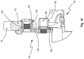
- Fig. 1A shows the state of the art according to DE'834 regarding a coaxial connection of a conventional standard bicycle derailleur to a frame dropout 12.
- a universal derailleur hanger (UDH) 14 is used for the derailleur assembly, which essentially comprises a UDH base plate 18, a UDH sleeve 20 and a UDH bolt 22 (hereinafter also referred to as axle bolt).
- the UDH bolt can also be referred to as an adapter.
- FIG. 1A A UDH washer 24 and a so-called B-disk 26 can also be seen.
- the B-disk is used to adjust the so-called chain gap and to stop a so-called B-screw when the rear derailleur is bouncing.
- the B-screw is used to adjust a front stop for the rear derailleur, for which the hanger or the derailleur hanger 14 has a front stop section.
- the dropout could also have a suitable front stop section in the area of the derailleur hanger that may be used.
- Fig. 11 to 14 represent a further embodiment for the connection between UDH bolt and UDH sleeve, or for the installation of a UDH in the dropout.
- the UDH bolt is positively locked by means of a bayonet-like lock, the structure and effect of which are particularly evident in a combination of Fig. 13 and 14 can be removed.
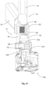
- Fig. 11 shows a complete conventional derailleur 16, which is mounted on the rear right dropout of the frame by means of a B-bolt 72 and the universal derailleur hanger 14 as well as the reinforcement element 70.
- the B-bolt 72 extends through a passage of the base element (B-knuckle) 74 and the already mentioned B-disk 26 and is screwed into the corresponding screw opening of the derailleur hanger base plate 18.
- the figure also shows the already mentioned B-screw 76, which is used in a conventional manner both to adjust the chain gap and to absorb derailleur impacts during bouncing.
- the derailleur can be freely pivoted backwards around the B-bolt against the chain tension.
- An arrow S represents an example of an impact direction on the derailleur, which runs through the B-bolt.
- the UDH base plate 18 with the overmolded UDH sleeve 20 is first inserted from the left into the opening of the frame dropout.
- the UDH bolt 22 is then inserted from the right into the opening of the UDH sleeve 20, whereby only one directional assembly is possible due to the corresponding shape of the bolt and UDH sleeve (two positions offset by 180° are possible here, see Fig. 14 ).
- the locking element 70 which here also forms the reinforcing element 70, is arranged or clamped between the head of the B-bolt 72 of the rear derailleur and the body of the so-called B-knuckle 74, similar to how this is also done, for example, in the Fig. 27 to 34 and the corresponding description is shown there.
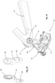
- Fig. 15 to 18 show an embodiment which, like the above embodiment according to Fig. 11 to 14 allows a two-arm assembly of a largely or completely unchanged conventional derailleur.
- this embodiment also uses a largely unchanged universal derailleur hanger (UDH) with screwed fastening in the dropout, as is known from DE'834 and e.g. in Fig. 1A
- the reinforcing element 70 therefore does not serve as a locking element in the sense explained.
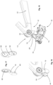
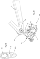
- Fig. 19 to 21 an embodiment is shown which largely corresponds to the embodiment described above according to Fig. 15 to 18
- the difference between this embodiment and the previous embodiment is only the connection of the lower end of the reinforcement element 70 with the B-bolt 72 of the derailleur 16.
- This connection is made here by means of an additional threaded insert, which is inserted or pressed into the existing hexagon socket profile of the B-bolt 72.
- the lower end of the reinforcement element 70 is in turn screwed to this threaded insert.
- the reinforcement element 70 has an opening or bore 96 instead of the pin 90, through which a fastening screw 98 is screwed into a screw opening of the threaded insert 94.
- a conventional B-bolt used into whose Allen head a suitable threaded insert is inserted or pressed. This results in a particularly strong, play-free and resilient connection between the lower end of the reinforcement element and the derailleur.
- a pin 90a is formed on the inside of the reinforcing element 70, which is provided with a screw-in opening for the fastening screw 100 fed from the other side (from the left).
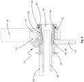
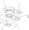
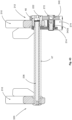
- FIG. 25 to 27 Another embodiment is shown in the Fig. 25 to 27 This embodiment differs from the embodiments described above according to Fig. 15 to 24 in particular by an increased integration of the reinforcing element into the overall arrangement, especially with the switching mechanism 16a.
- the B-knuckle bearing body of which is only slightly shortened axially to make room for the lower eye 82a of the reinforcing element 70, which is smaller than the lower eye 82 of the above-mentioned Embodiment has a larger diameter for a non-clamping design.
- 102 designates the bearing head of the B-knuckle 74 and 104 the head of the B-bolt 72.
- the bolt head 104 of the tightened B-bolt 72 is supported on the derailleur hanger base plate 18 by means of the B-disk 26 via a bearing bush 106 inserted between the B-bolt and the bearing head 102.
- the B-disk is also provided here as in the conventional derailleur, as a stop for the B-screw 76 during derailleur bouncing.
- the rear derailleur can thus be freely pivoted backwards against the chain tension as is conventional, so that the reinforcement element achieves the structural improvement explained with regard to lateral rigidity, but not yet a functional improvement with regard to energy dissipation through friction when pivoting the rear derailleur backwards, as is also possible in principle and will be explained below using a further embodiment.
- FIG. 27 A comparison of Fig. 27 with for example Fig. 21 shows that in the embodiment according to Fig. 25 to 27 the reinforcing element 70 no longer engages the B-bolt 72 of the derailleur 16a from the outside on the right as in the embodiments described above according to Fig. 15 to 24 , but here is arranged by means of its lower eye 82a between the head 104 of the B-bolt 72 and the bearing housing of the derailleur B-knuckle.
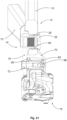
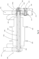
- Fig. 28 to 30 is compared to the above embodiment according to Fig. 25 and 27 externally almost indistinguishable, as a summary of the Fig. 28 and 25 shows. From a summary of the Fig. 30 and 27 However, it becomes clear that the two embodiments differ in the area of the bearing of the B-Knuckle 74.
- the embodiment according to Fig. 28 to 30 compared to the conventional, one-sided derailleur assembly both comparable structural improvements in terms of lateral stiffness and comparable functional improvements, in particular with regard to the prevention of the undesirable so-called derailleur bouncing (the impact in the area of the B-screw and B-disk described below), as is the case with the derailleurs known from EP'324 with two-arm B-knuckle and rear axle coaxial fastening compared to the conventional derailleur mounting.
- Fig. 33 shows similar to already Fig. 30 furthermore, the clamping force flow K3, which in this and the previous embodiment is generated by the B-bolt 72, and which fixes the B-knuckle 74 of the derailleur 16c, as described above, rotationally relative to the derailleur hanger 14.
- Fig. 33 is also representative of all embodiments according to Fig. 15 to 37 the force flow K4 which fixes the universal derailleur hanger (UDH) in the frame dropout when the thru axle is loose is shown.
- UDH universal derailleur hanger
- FIG. 44 to 46 Another embodiment for a two-arm arrangement is shown in Fig. 44 to 46 This embodiment has at first glance considerable similarity to the previous embodiment according to Fig. 41 to 43 .
- K8-3 designates the torque from the B-knuckle to the B-screw
- K8-4 designates the torque from the B-screw to the B-disk
- K8-5 designates the torque from the B-disk to the dropout and thus the frame.
- the force flow (K7) is the force flow when the quick release axle is screwed on.
- the B-knuckle is clamped in a rotational manner by this force flow when the quick release axle is screwed on, absorbing energy, similar to EP '324, paragraph [0082], Fig.4 , 16 and 24a.
- the power flow without a quick-release axle is designated with (K6) and holds the B-knuckle 20 (74), the axle bolt 60 (22), the compensation bushing 408 and the B-disk (26) together without stress by means of the snap ring 406, so that the B-knuckle can be freely pivoted backwards for wheel removal.
- the type A deraille or base elements achieve a much stiffer overall system, which contributes greatly to better shifting quality.
- the system is also less susceptible to bending when subjected to shocks/impacts.
- the idea of the invention is to use a material or element 450 that absorbs the load from the impact and deforms.
- the material or element is designed or constructed in such a way that the B-knuckle 20 (74) can easily be bent back into its original position several times, preferably without the need to use an additional tool.
- any material can be used, e.g. metal or plastic, which is suitable for being bent back again, be it elastic or plastic.
- This material or element connects and holds in position an upper part of the B-knuckle, which is attached to the bicycle frame, to the lower part of the B-knuckle, which holds the parallelogram.
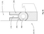
- a simple plug, plug, pin, insert or the like (see item 452 in Fig. 56 ) to hold the two parts in place. It can be a breakaway element, whose strength is set to a certain value, which is weaker than the force required to deform the derailleur parts. This element can be replaced by a spare element after realignment or repair.
- a snap-in connection 456 is provided.
- this solution should also include an end stop that prevents the derailleur from colliding with elements of the wheel such as spokes, in order to prevent further damage to the wheel.
- This solution corresponds to solution i), but the flexible material or element is replaced by a coupling 458, which also makes the predetermined breaking element unnecessary. It can be a friction clutch, for example in the form of a so-called slip clutch.
- the clutch allows the rear derailleur to move in the event of an impact/crash.
- the clutch can be indexed to take on the function of an end stop (which is also possible in principle).
- a marking or display for example in the form of a graphic element 460, can be provided on the B-knuckle 20 (74) in order to make the straightness or deviation from the straightness of the B-knuckle easily recognizable.
- a straight line can be used as a graphic element or marker.
- Figures 59 and 60 explain this possibility by way of example.
- Another possibility is an element that can be measured or detected with a special measuring device.
- the derailleur is repaired by using a new predetermined breaking element 462 and reassembling the B-knuckle, which is held in the assembled state by the predetermined breaking element and, if necessary, suitable engagement and counter-engagement formations 470 and 472 of the two B-knuckle parts.
- the predetermined breaking element 462 can be designed, for example, in the form of a plug or a pin.
Landscapes
- Engineering & Computer Science (AREA)
- Mechanical Engineering (AREA)
- Chemical & Material Sciences (AREA)
- Combustion & Propulsion (AREA)
- Transportation (AREA)
- Axle Suspensions And Sidecars For Cycles (AREA)
- General Engineering & Computer Science (AREA)
- Automatic Cycles, And Cycles In General (AREA)
Applications Claiming Priority (3)
| Application Number | Priority Date | Filing Date | Title |
|---|---|---|---|
| DE102019008796 | 2019-12-18 | ||
| DE102020132208.9A DE102020132208A1 (de) | 2019-12-18 | 2020-12-03 | Fahrrad-Schaltwerk und Anbindung eines Schaltwerks an einem Fahrrad-Rahmen |
| EP20000455.4A EP3838731B1 (fr) | 2019-12-18 | 2020-12-10 | Dérailleur de bicyclette et raccordement d'un dérailleur à un cadre de bicyclette |
Related Parent Applications (1)
| Application Number | Title | Priority Date | Filing Date |
|---|---|---|---|
| EP20000455.4A Division EP3838731B1 (fr) | 2019-12-18 | 2020-12-10 | Dérailleur de bicyclette et raccordement d'un dérailleur à un cadre de bicyclette |
Publications (2)
| Publication Number | Publication Date |
|---|---|
| EP4393804A2 true EP4393804A2 (fr) | 2024-07-03 |
| EP4393804A3 EP4393804A3 (fr) | 2024-12-11 |
Family
ID=76205954
Family Applications (1)
| Application Number | Title | Priority Date | Filing Date |
|---|---|---|---|
| EP24020139.2A Pending EP4393804A3 (fr) | 2019-12-18 | 2020-12-10 | Dérailleur de bicyclette et raccordement d'un dérailleur à un cadre de bicyclette |
Country Status (5)
| Country | Link |
|---|---|
| US (2) | US11939029B2 (fr) |
| EP (1) | EP4393804A3 (fr) |
| CN (1) | CN113002690B (fr) |
| DE (1) | DE102020132208A1 (fr) |
| TW (1) | TWI895311B (fr) |
Families Citing this family (14)
| Publication number | Priority date | Publication date | Assignee | Title |
|---|---|---|---|---|
| TWI730290B (zh) * | 2019-02-13 | 2021-06-11 | 彥豪金屬工業股份有限公司 | 自行車後變速器的固定組件 |
| DE102020201229A1 (de) * | 2019-03-22 | 2020-09-24 | Sram Deutschland Gmbh | Koaxiale Schaltwerksanbindung |
| EP3838731B1 (fr) * | 2019-12-18 | 2024-05-15 | SRAM Deutschland GmbH | Dérailleur de bicyclette et raccordement d'un dérailleur à un cadre de bicyclette |
| DE102020132208A1 (de) * | 2019-12-18 | 2021-06-24 | Sram Deutschland Gmbh | Fahrrad-Schaltwerk und Anbindung eines Schaltwerks an einem Fahrrad-Rahmen |
| EP3964437B1 (fr) * | 2020-09-03 | 2024-12-18 | SRAM Deutschland GmbH | Dérailleur arrière électromécanique pour montage coaxial pourvu de dispositif de blocage |
| US12221191B2 (en) | 2020-12-03 | 2025-02-11 | Sram Deutschland Gmbh | Rear derailleur |
| DE102021131414A1 (de) | 2020-12-03 | 2022-06-09 | Sram Deutschland Gmbh | Hinteres Schaltwerk zur koaxialen Anbindung an einem Fahrrad-Rahmen |
| TWI867135B (zh) | 2020-12-31 | 2024-12-21 | 日商島野股份有限公司 | 托架裝置 |
| TWI895327B (zh) * | 2020-12-31 | 2025-09-01 | 日商島野股份有限公司 | 後撥鏈器 |
| DE102022115599A1 (de) | 2021-06-29 | 2022-12-29 | Sram Deutschland Gmbh | Modulares Fahrrad-Schaltwerk |
| CN115675720A (zh) * | 2021-07-26 | 2023-02-03 | 株式会社岛野 | 支架装置 |
| TWI800929B (zh) * | 2021-09-27 | 2023-05-01 | 彥豪金屬工業股份有限公司 | 自行車後變速器 |
| US12441435B2 (en) * | 2021-11-29 | 2025-10-14 | Shimano Inc. | Bracket apparatus and bracket assembly |
| US12552493B2 (en) * | 2024-05-02 | 2026-02-17 | Shimano Inc. | Derailleur hanger |
Citations (5)
| Publication number | Priority date | Publication date | Assignee | Title |
|---|---|---|---|---|
| DE102018001253A1 (de) | 2017-03-20 | 2018-09-20 | Sram Deutschland Gmbh | Hinteres Schaltwerk zur koaxialen Montage |
| EP3556643A1 (fr) | 2018-04-20 | 2019-10-23 | SRAM Deutschland GmbH | Patte de dérailleur destiné au montage d'un mécanisme de commutation arrière à un cadre de bicyclette et ensemble de composants destiné au montage sélectif du mécanisme de commutation arrière alternatif au cadre de bicyclette |
| EP3670315A2 (fr) | 2018-12-21 | 2020-06-24 | SRAM Deutschland GmbH | Élément de retenue et bicyclette dotée d'un élément de retenue |
| EP3712052A1 (fr) | 2019-03-22 | 2020-09-23 | SRAM Deutschland GmbH | Raccordement coaxial de monte-et-baisse |
| US20200298933A1 (en) | 2019-03-22 | 2020-09-24 | Sram Deutschland Gmbh | Coaxial gearshift mechanism connection |
Family Cites Families (72)
| Publication number | Priority date | Publication date | Assignee | Title |
|---|---|---|---|---|
| GB722363A (en) * | 1951-08-24 | 1955-01-26 | Juy Lucien Charles Hippolyte | Change speed gear of the chain shifting type for bicycles and the like vehicles |
| US4215872A (en) * | 1979-02-07 | 1980-08-05 | Clark Marion A | Positive shift derailleur mechanism |
| FR2508862A1 (fr) * | 1981-07-03 | 1983-01-07 | Simplex Ets | Dispositif de commande assurant des positions multiples preetablies et controlees, applicable en particulier aux changements de vitesse pour les cycles et vehicules similaires |
| JPH0226794Y2 (fr) * | 1985-06-17 | 1990-07-20 | ||
| US4789379A (en) * | 1987-10-06 | 1988-12-06 | Maeda Industries, Ltd. | Bicycle deraileur |
| JP3375163B2 (ja) * | 1993-02-03 | 2003-02-10 | 株式会社シマノ | 自転車用リヤディレーラ |
| US6102421A (en) * | 1996-03-15 | 2000-08-15 | Schwinn Cycling & Fitness Inc. | Rear suspension for a bicycle |
| US5931753A (en) * | 1998-02-09 | 1999-08-03 | Shimano, Inc. | Rear deraileur with shock absorber |
| US6015360A (en) * | 1998-06-17 | 2000-01-18 | Falcon Industrial Co., Ltd. | Automatic gearshifting device of multi-stage fly wheel of bicycle |
| US6287228B1 (en) * | 1999-11-12 | 2001-09-11 | Shimano, Inc. | Rear derailleur with cable guide roller |
| US20030171176A1 (en) * | 2002-03-07 | 2003-09-11 | Shimano, Inc. | Bicycle rear derailleur |
| JP3645872B2 (ja) * | 2002-07-29 | 2005-05-11 | 株式会社シマノ | 自転車用リアディレーラ |
| JP3708515B2 (ja) * | 2002-10-30 | 2005-10-19 | 株式会社シマノ | 自転車用リアディレーラ |
| JP3667312B2 (ja) * | 2002-10-30 | 2005-07-06 | 株式会社シマノ | 自転車用リアディレーラ |
| JP2004189168A (ja) * | 2002-12-13 | 2004-07-08 | Shimano Inc | 自転車用リアディレーラ |
| US7033294B2 (en) * | 2003-06-11 | 2006-04-25 | Specialized Bicycle Components | Bicycle rear derailleur guard |
| US20060172831A1 (en) * | 2005-01-31 | 2006-08-03 | Yi-Ling Wen | Holding device for a rear derailleur of a bicycle |
| JP2006213268A (ja) * | 2005-02-07 | 2006-08-17 | Shimano Inc | 自転車用リアディレーラ |
| US20070021246A1 (en) * | 2005-07-19 | 2007-01-25 | Shimano Inc. | Bicycle rear derailleur |
| US7666111B2 (en) * | 2005-07-19 | 2010-02-23 | Shimano Inc. | Bicycle rear derailleur |
| US8419573B2 (en) * | 2005-07-28 | 2013-04-16 | Shimano Inc. | Bicycle rear derailleur |
| US20080051237A1 (en) * | 2006-08-24 | 2008-02-28 | Shimano Inc. | Bicycle rear derailleur |
| US7905804B2 (en) * | 2006-09-08 | 2011-03-15 | Shimano Inc. | Bicycle derailleur |
| US20080081716A1 (en) * | 2006-09-25 | 2008-04-03 | Shimano Inc. | Bicycle rear derailleur |
| US7614972B2 (en) * | 2006-11-28 | 2009-11-10 | Shimano Inc. | Bicycle rear derailleur |
| US7824285B2 (en) * | 2006-12-20 | 2010-11-02 | Shimano (Singapore) Pte. Ltd. | Bicycle rear derailleur |
| US7703785B2 (en) * | 2007-08-16 | 2010-04-27 | Trek Bicycle Corporation | Bicycle derailleur system |
| US20080272253A1 (en) * | 2007-05-03 | 2008-11-06 | Peng-Yu Tseng | Derailleurbracket for a bicycle |
| DE202007006451U1 (de) * | 2007-05-05 | 2007-10-25 | Grätz, Michael | Steckachssystem zur Radbefestigung |
| IL186237A (en) * | 2007-09-24 | 2013-11-28 | Alon Schaffer | Flexible rack for bicycle gear |
| US7942767B2 (en) | 2007-12-19 | 2011-05-17 | Shimano, Inc. | Bicycle derailleur with multiple mounting adjustments |
| GB201014276D0 (en) * | 2010-08-26 | 2010-10-13 | Imp Innovations Ltd | Variable-geometry suspension apparatus and vehicle comprising such apparatus |
| ES2369287B1 (es) * | 2011-08-11 | 2012-10-16 | Orbea S. Coop. Ltda. | Conjunto-cuadro para construir un cuadro de bicicleta cuya puntera permite el montaje de diferentes tipos de eje rueda. |
| DE102011118912A1 (de) * | 2011-11-18 | 2013-05-23 | Sram Deutschland Gmbh | Umwerfereinrichtung für eine Fahrradschaltung, insbesondere hintere Umwerfereinrichtung |
| US9010792B2 (en) * | 2012-03-16 | 2015-04-21 | Specialized Bicycle Components, Inc. | Torque element for a motor-driven bicycle |
| US9334016B2 (en) * | 2012-07-13 | 2016-05-10 | Shimano Inc. | Bicycle rear derailleur |
| US8899606B2 (en) * | 2012-07-24 | 2014-12-02 | Chris Cocalis | Removable dropouts for bicycle frame |
| ITMI20130251A1 (it) * | 2013-02-22 | 2014-08-23 | Campagnolo Srl | Cambio di bicicletta a precisione di comando migliorata |
| US9227465B2 (en) * | 2013-04-16 | 2016-01-05 | Shimano Inc. | Bicycle wheel securing structure |
| DE102013014336A1 (de) * | 2013-08-28 | 2015-03-05 | Winora-Staiger Gmbh | Fahrradrahmen aus faserverstärktem Werkstoff mit Adapterplatten für das Hinterrad |
| ITMI20131949A1 (it) * | 2013-11-22 | 2015-05-23 | Campagnolo Srl | Dispositivo di montaggio di un deragliatore di un cambio posteriore su un telaio di bicicletta |
| US9308961B2 (en) * | 2013-11-27 | 2016-04-12 | Specialized Bicycle Components, Inc. | Bicycle frame with convertible dropouts |
| US20160039494A1 (en) * | 2014-08-08 | 2016-02-11 | Cycling Sports Group, Inc. | Bicycle with pivoting derailleur hanger |
| ITMI20142069A1 (it) * | 2014-12-02 | 2016-06-02 | Campagnolo Srl | Deragliatore di un cambio di bicicletta e metodo per controllare elettronicamente un cambio di bicicletta |
| FR3036312B1 (fr) * | 2015-05-21 | 2017-06-02 | Cycles Lapierre | Patte de derailleur |
| FR3046399A1 (fr) * | 2015-12-31 | 2017-07-07 | Cycles Lapierre | Support d'etrier de frein a disque pour une bicyclette ou similaire |
| FR3046400B1 (fr) * | 2015-12-31 | 2019-05-10 | Cycles Lapierre | Patte de bras arriere d'une bicyclette ou analogue et bicyclette comportant une telle patte de bras arriere |
| AU2017307605B2 (en) * | 2016-08-04 | 2023-09-21 | Level One Engineering Llc | Bicycle rear suspension system |
| US10472019B2 (en) * | 2016-08-18 | 2019-11-12 | Wolf Tooth Components, Inc. | Axle mounting system |
| KR102406109B1 (ko) * | 2016-09-02 | 2022-06-07 | 현대자동차 주식회사 | 드롭 아웃을 갖는 자전거 프레임구조 |
| US10793222B1 (en) * | 2017-03-21 | 2020-10-06 | Jonathan K. Harris | Bicycle derailleur having upper and lower alignment assemblies |
| TWI641531B (zh) * | 2017-05-31 | 2018-11-21 | 彥豪金屬工業股份有限公司 | 自行車後變速器 |
| US10464634B2 (en) * | 2017-07-12 | 2019-11-05 | Shimano Inc. | Bicycle rear derailleur |
| US10981626B2 (en) * | 2018-03-20 | 2021-04-20 | Sram Deutschland Gmbh | Drive arrangement for a bicycle |
| ES2693614B2 (es) * | 2018-04-09 | 2019-10-17 | Rotor Componentes Tecnologicos S L | Dispositivo de cambio de marchas trasero de bicicleta |
| EP3556647B1 (fr) * | 2018-04-20 | 2021-11-17 | YT Industries GmbH | Dispositif de fixation d'un dispositif de commutation à un cadre de bicyclette |
| DE102018214218A1 (de) * | 2018-08-22 | 2020-02-27 | Sram Deutschland Gmbh | Hinterrad-Kettenschaltwerk mit exzentrischer Seilzug-Umlenkrollenanordung mit Übersetzungsverhältnis |
| TWI730290B (zh) * | 2019-02-13 | 2021-06-11 | 彥豪金屬工業股份有限公司 | 自行車後變速器的固定組件 |
| EP4253217A3 (fr) * | 2019-04-25 | 2024-03-20 | SRAM Deutschland GmbH | Derailleur électromécanique destiné au montage coaxial |
| DE102020000827A1 (de) * | 2019-04-25 | 2020-10-29 | Sram Deutschland Gmbh | Elektromechanisches Schaltwerk zur koaxialen Montage |
| DE102020132208A1 (de) * | 2019-12-18 | 2021-06-24 | Sram Deutschland Gmbh | Fahrrad-Schaltwerk und Anbindung eines Schaltwerks an einem Fahrrad-Rahmen |
| EP3838731B1 (fr) * | 2019-12-18 | 2024-05-15 | SRAM Deutschland GmbH | Dérailleur de bicyclette et raccordement d'un dérailleur à un cadre de bicyclette |
| EP3904193B1 (fr) * | 2020-04-30 | 2024-08-28 | Fantic Motor S.p.A. | Dispositif de positionnement sélectif de pivot d'une roue |
| TWI742700B (zh) * | 2020-05-29 | 2021-10-11 | 彥豪金屬工業股份有限公司 | 自行車後變速器 |
| US12221191B2 (en) * | 2020-12-03 | 2025-02-11 | Sram Deutschland Gmbh | Rear derailleur |
| TWI867135B (zh) * | 2020-12-31 | 2024-12-21 | 日商島野股份有限公司 | 托架裝置 |
| TWI895327B (zh) * | 2020-12-31 | 2025-09-01 | 日商島野股份有限公司 | 後撥鏈器 |
| CN218141972U (zh) * | 2021-06-29 | 2022-12-27 | Sram德国有限公司 | 自行车换挡机构及用于自行车换挡机构的马达传动单元 |
| TWI800929B (zh) * | 2021-09-27 | 2023-05-01 | 彥豪金屬工業股份有限公司 | 自行車後變速器 |
| US12441435B2 (en) * | 2021-11-29 | 2025-10-14 | Shimano Inc. | Bracket apparatus and bracket assembly |
| US12351272B2 (en) * | 2021-11-29 | 2025-07-08 | Shimano Inc. | Bracket apparatus |
| US12441436B2 (en) * | 2021-11-29 | 2025-10-14 | Shimano Inc. | Bracket apparatus |
-
2020
- 2020-12-03 DE DE102020132208.9A patent/DE102020132208A1/de active Pending
- 2020-12-10 EP EP24020139.2A patent/EP4393804A3/fr active Pending
- 2020-12-17 CN CN202011493530.6A patent/CN113002690B/zh active Active
- 2020-12-17 US US17/125,027 patent/US11939029B2/en active Active
- 2020-12-17 TW TW109144724A patent/TWI895311B/zh active
-
2024
- 2024-10-17 US US18/918,417 patent/US20250042505A1/en active Pending
Patent Citations (12)
| Publication number | Priority date | Publication date | Assignee | Title |
|---|---|---|---|---|
| DE102018001253A1 (de) | 2017-03-20 | 2018-09-20 | Sram Deutschland Gmbh | Hinteres Schaltwerk zur koaxialen Montage |
| US20180265169A1 (en) | 2017-03-20 | 2018-09-20 | Sram Deutschland Gmbh | Rear gearshift mechanism for coaxial installation |
| EP3388324A2 (fr) | 2017-03-20 | 2018-10-17 | SRAM Deutschland GmbH | Derailleur arrière destiné au montage coaxial |
| EP3556643A1 (fr) | 2018-04-20 | 2019-10-23 | SRAM Deutschland GmbH | Patte de dérailleur destiné au montage d'un mécanisme de commutation arrière à un cadre de bicyclette et ensemble de composants destiné au montage sélectif du mécanisme de commutation arrière alternatif au cadre de bicyclette |
| US20190322333A1 (en) | 2018-04-20 | 2019-10-24 | Sram Deutschland Gmbh | Derailleur hanger |
| DE102018206104A1 (de) | 2018-04-20 | 2019-10-24 | Sram Deutschland Gmbh | Schaltauge zur Montage eines hinteren Schaltwerks an einem Fahrradrahmen und Set von Komponenten zur wahlweisen Montage alternativer hinterer Schaltwerke an dem Fahrradrahmen |
| EP3670315A2 (fr) | 2018-12-21 | 2020-06-24 | SRAM Deutschland GmbH | Élément de retenue et bicyclette dotée d'un élément de retenue |
| US20200198728A1 (en) | 2018-12-21 | 2020-06-25 | Sram Deutschland Gmbh | Bicycle bracket element |
| DE102018222834A1 (de) | 2018-12-21 | 2020-06-25 | Sram Deutschland Gmbh | Halterungselement und Fahrrad mit einem Halterungselement |
| EP3712052A1 (fr) | 2019-03-22 | 2020-09-23 | SRAM Deutschland GmbH | Raccordement coaxial de monte-et-baisse |
| US20200298933A1 (en) | 2019-03-22 | 2020-09-24 | Sram Deutschland Gmbh | Coaxial gearshift mechanism connection |
| DE102020201229A1 (de) | 2019-03-22 | 2020-09-24 | Sram Deutschland Gmbh | Koaxiale Schaltwerksanbindung |
Also Published As
| Publication number | Publication date |
|---|---|
| CN113002690B (zh) | 2024-08-20 |
| US20210188396A1 (en) | 2021-06-24 |
| US20250042505A1 (en) | 2025-02-06 |
| TWI895311B (zh) | 2025-09-01 |
| US11939029B2 (en) | 2024-03-26 |
| EP4393804A3 (fr) | 2024-12-11 |
| CN113002690A (zh) | 2021-06-22 |
| TW202124213A (zh) | 2021-07-01 |
| DE102020132208A1 (de) | 2021-06-24 |
Similar Documents
| Publication | Publication Date | Title |
|---|---|---|
| EP4393804A2 (fr) | Dérailleur de bicyclette et raccordement d'un dérailleur à un cadre de bicyclette | |
| EP3838731B1 (fr) | Dérailleur de bicyclette et raccordement d'un dérailleur à un cadre de bicyclette | |
| EP3556643B1 (fr) | Patte de dérailleur destiné au montage d'un mécanisme de commutation arrière à un cadre de bicyclette et ensemble de composants destiné au montage sélectif de mécanismes alternatifs de commutation arrière au cadre de bicyclette | |
| EP3388324B1 (fr) | Derailleur arrière destiné au montage coaxial | |
| DE102020201229A1 (de) | Koaxiale Schaltwerksanbindung | |
| EP4063250B1 (fr) | Élément de retenue et bicyclette dotée d'un élément de retenue | |
| DE102008043354B4 (de) | Fahrradbauteil-Befestigungsstruktur | |
| EP4008622B1 (fr) | Mécanisme de commutation arrière destiné à la liaison coaxiale à un cadre de bicyclette | |
| EP1912806B1 (fr) | Bras oscillant de suspension | |
| DE102010010317B4 (de) | Fahrradrahmen mit gelenkiger Gestänge-Befestigungsanordnung | |
| EP2100806B1 (fr) | Composant de bicyclette | |
| EP3712052B1 (fr) | Raccordement coaxial de monte-et-baisse | |
| DE3212842A1 (de) | Spureinstellvorrichtung fuer ein fahrzeug | |
| EP2158120A1 (fr) | Patte de dérailleur avec aide à l'installation | |
| DE10013726C2 (de) | Klappenscharnier | |
| EP2125499A1 (fr) | Axe de blocage rapide | |
| EP3649354A1 (fr) | Système de fixation d'un axe de pivotement à un châssis de véhicule, châssis pour relier un axe de pivotement et procédé de montage d'un axe de pivotement à un châssis de véhicule | |
| DE29903826U1 (de) | Vorrichtung für Federspanner zum Ausrichten eines Federtellers | |
| DE10321043B3 (de) | Montagehilfe und Verfahren für das reproduzierbare Positionieren eines Scharniers | |
| DE102023119709A1 (de) | Fahrradschaltwerk und Verfahren zum Montieren eines Fahrradschaltwerks | |
| DE102021131414A1 (de) | Hinteres Schaltwerk zur koaxialen Anbindung an einem Fahrrad-Rahmen | |
| AT9214U1 (de) | Anordnung zur lenkungsdämpfung der vorderradgabel eines fahrrades | |
| DE102010015355A1 (de) | Klemmverbindung, insbesondere für ein Fahrrad | |
| WO2004113155A1 (fr) | Dispositif de pivotement | |
| DE102007009406A1 (de) | Achsenanordnung |
Legal Events
| Date | Code | Title | Description |
|---|---|---|---|
| PUAI | Public reference made under article 153(3) epc to a published international application that has entered the european phase |
Free format text: ORIGINAL CODE: 0009012 |
|
| STAA | Information on the status of an ep patent application or granted ep patent |
Free format text: STATUS: THE APPLICATION HAS BEEN PUBLISHED |
|
| AC | Divisional application: reference to earlier application |
Ref document number: 3838731 Country of ref document: EP Kind code of ref document: P |
|
| AK | Designated contracting states |
Kind code of ref document: A2 Designated state(s): AL AT BE BG CH CY CZ DE DK EE ES FI FR GB GR HR HU IE IS IT LI LT LU LV MC MK MT NL NO PL PT RO RS SE SI SK SM TR |
|
| PUAL | Search report despatched |
Free format text: ORIGINAL CODE: 0009013 |
|
| AK | Designated contracting states |
Kind code of ref document: A3 Designated state(s): AL AT BE BG CH CY CZ DE DK EE ES FI FR GB GR HR HU IE IS IT LI LT LU LV MC MK MT NL NO PL PT RO RS SE SI SK SM TR |
|
| RIC1 | Information provided on ipc code assigned before grant |
Ipc: B62K 25/02 20060101AFI20241107BHEP |
|
| STAA | Information on the status of an ep patent application or granted ep patent |
Free format text: STATUS: REQUEST FOR EXAMINATION WAS MADE |
|
| 17P | Request for examination filed |
Effective date: 20250610 |
|
| STAA | Information on the status of an ep patent application or granted ep patent |
Free format text: STATUS: EXAMINATION IS IN PROGRESS |
|
| 17Q | First examination report despatched |
Effective date: 20260205 |