EP4008657B1 - Procédé de détection et de suivi d'une caractéristique d'une bande de matériau d'emballage - Google Patents
Procédé de détection et de suivi d'une caractéristique d'une bande de matériau d'emballage Download PDFInfo
- Publication number
- EP4008657B1 EP4008657B1 EP21210405.3A EP21210405A EP4008657B1 EP 4008657 B1 EP4008657 B1 EP 4008657B1 EP 21210405 A EP21210405 A EP 21210405A EP 4008657 B1 EP4008657 B1 EP 4008657B1
- Authority
- EP
- European Patent Office
- Prior art keywords
- capacitor
- web
- packaging material
- feature
- capacitance
- Prior art date
- Legal status (The legal status is an assumption and is not a legal conclusion. Google has not performed a legal analysis and makes no representation as to the accuracy of the status listed.)
- Active
Links
Images

Classifications
-
- B—PERFORMING OPERATIONS; TRANSPORTING
- B65—CONVEYING; PACKING; STORING; HANDLING THIN OR FILAMENTARY MATERIAL
- B65B—MACHINES, APPARATUS OR DEVICES FOR, OR METHODS OF, PACKAGING ARTICLES OR MATERIALS; UNPACKING
- B65B57/00—Automatic control, checking, warning, or safety devices
- B65B57/02—Automatic control, checking, warning, or safety devices responsive to absence, presence, abnormal feed, or misplacement of binding or wrapping material, containers, or packages
-
- B—PERFORMING OPERATIONS; TRANSPORTING
- B65—CONVEYING; PACKING; STORING; HANDLING THIN OR FILAMENTARY MATERIAL
- B65H—HANDLING THIN OR FILAMENTARY MATERIAL, e.g. SHEETS, WEBS, CABLES
- B65H26/00—Warning or safety devices, e.g. automatic fault detectors, stop-motions, for web-advancing mechanisms
- B65H26/02—Warning or safety devices, e.g. automatic fault detectors, stop-motions, for web-advancing mechanisms responsive to presence of irregularities in running webs
-
- B—PERFORMING OPERATIONS; TRANSPORTING
- B65—CONVEYING; PACKING; STORING; HANDLING THIN OR FILAMENTARY MATERIAL
- B65B—MACHINES, APPARATUS OR DEVICES FOR, OR METHODS OF, PACKAGING ARTICLES OR MATERIALS; UNPACKING
- B65B51/00—Devices for, or methods of, sealing or securing package folds or closures; Devices for gathering or twisting wrappers, or necks of bags
- B65B51/10—Applying or generating heat or pressure or combinations thereof
- B65B51/26—Devices specially adapted for producing transverse or longitudinal seams in webs or tubes
- B65B51/30—Devices, e.g. jaws, for applying pressure and heat, e.g. for subdividing filled tubes
-
- B—PERFORMING OPERATIONS; TRANSPORTING
- B65—CONVEYING; PACKING; STORING; HANDLING THIN OR FILAMENTARY MATERIAL
- B65B—MACHINES, APPARATUS OR DEVICES FOR, OR METHODS OF, PACKAGING ARTICLES OR MATERIALS; UNPACKING
- B65B9/00—Enclosing successive articles, or quantities of material, e.g. liquids or semiliquids, in flat, folded, or tubular webs of flexible sheet material; Subdividing filled flexible tubes to form packages
- B65B9/06—Enclosing successive articles, or quantities of material, in a longitudinally-folded web, or in a web folded into a tube about the articles or quantities of material placed upon it
- B65B9/08—Enclosing successive articles, or quantities of material, in a longitudinally-folded web, or in a web folded into a tube about the articles or quantities of material placed upon it in a web folded and sealed transversely to form pockets which are subsequently filled and then closed by sealing
-
- G—PHYSICS
- G01—MEASURING; TESTING
- G01B—MEASURING LENGTH, THICKNESS OR SIMILAR LINEAR DIMENSIONS; MEASURING ANGLES; MEASURING AREAS; MEASURING IRREGULARITIES OF SURFACES OR CONTOURS
- G01B7/00—Measuring arrangements characterised by the use of electric or magnetic techniques
- G01B7/02—Measuring arrangements characterised by the use of electric or magnetic techniques for measuring length, width or thickness
- G01B7/06—Measuring arrangements characterised by the use of electric or magnetic techniques for measuring length, width or thickness for measuring thickness
- G01B7/08—Measuring arrangements characterised by the use of electric or magnetic techniques for measuring length, width or thickness for measuring thickness using capacitive means
- G01B7/087—Measuring arrangements characterised by the use of electric or magnetic techniques for measuring length, width or thickness for measuring thickness using capacitive means for measuring of objects while moving
-
- B—PERFORMING OPERATIONS; TRANSPORTING
- B65—CONVEYING; PACKING; STORING; HANDLING THIN OR FILAMENTARY MATERIAL
- B65H—HANDLING THIN OR FILAMENTARY MATERIAL, e.g. SHEETS, WEBS, CABLES
- B65H2301/00—Handling processes for sheets or webs
- B65H2301/40—Type of handling process
- B65H2301/46—Splicing
- B65H2301/4601—Splicing special splicing features or applications
- B65H2301/46018—Splicing special splicing features or applications involving location or further processing of splice
- B65H2301/460186—Splicing special splicing features or applications involving location or further processing of splice detect location of splice
-
- B—PERFORMING OPERATIONS; TRANSPORTING
- B65—CONVEYING; PACKING; STORING; HANDLING THIN OR FILAMENTARY MATERIAL
- B65H—HANDLING THIN OR FILAMENTARY MATERIAL, e.g. SHEETS, WEBS, CABLES
- B65H2511/00—Dimensions; Position; Numbers; Identification; Occurrences
- B65H2511/10—Size; Dimensions
- B65H2511/13—Thickness
-
- B—PERFORMING OPERATIONS; TRANSPORTING
- B65—CONVEYING; PACKING; STORING; HANDLING THIN OR FILAMENTARY MATERIAL
- B65H—HANDLING THIN OR FILAMENTARY MATERIAL, e.g. SHEETS, WEBS, CABLES
- B65H2515/00—Physical entities not provided for in groups B65H2511/00 or B65H2513/00
- B65H2515/70—Electrical or magnetic properties, e.g. electric power or current
-
- B—PERFORMING OPERATIONS; TRANSPORTING
- B65—CONVEYING; PACKING; STORING; HANDLING THIN OR FILAMENTARY MATERIAL
- B65H—HANDLING THIN OR FILAMENTARY MATERIAL, e.g. SHEETS, WEBS, CABLES
- B65H2553/00—Sensing or detecting means
- B65H2553/20—Sensing or detecting means using electric elements
- B65H2553/23—Capacitive detectors, e.g. electrode arrangements
-
- B—PERFORMING OPERATIONS; TRANSPORTING
- B65—CONVEYING; PACKING; STORING; HANDLING THIN OR FILAMENTARY MATERIAL
- B65H—HANDLING THIN OR FILAMENTARY MATERIAL, e.g. SHEETS, WEBS, CABLES
- B65H2557/00—Means for control not provided for in groups B65H2551/00 - B65H2555/00
- B65H2557/60—Details of processes or procedures
- B65H2557/62—Details of processes or procedures for web tracking, i.e. retrieving a certain position of a web
Definitions
- the invention relates to packaging technology. More particularly, it is related to a method for detecting and tracking features of a web of packaging material.
- packaging material for the packages is provided on reels of packaging material. By unwinding the reel, a web of packaging material is formed and fed into the machine, where it is, in turn, formed, filled with product and made into individual packages.
- a prior art machinery and method are disclosed in e.g. US 3,519,922 .
- ASU automatic splicing unit
- a current solution of detecting the splice, deployed in many roll-fed packaging machines employs a bearing that is rotating on the packaging material and a lever system that is maintaining the bearing in position. Whenever the bearing is passing on the splice, it moves up or down. This movement can be amplified by the lever system and hence the presence of the splice can be detected.
- the features may be detected by identifying a change in capacitance of a capacitor, in which the web forms part, and based on this change the features can be detected.
- a method for detecting and/or tracking a feature of a web of packaging material using a first capacitor placed at a distance (d) from the web of packaging material comprises;
- the packaging material may be made of multiple layers.
- the packaging material may comprise a paper board layer.
- the packaging material may comprise a metallic layer, such as an Aluminium foil.
- the term feature may refer to an anomaly in the packaging material of the web.
- the presence of the feature may be relevant to detect and track through a production line in order to optimize or alter the process.
- the step of measuring the capacitance may comprise injecting a known amount of charges to the first capacitor and measuring the voltage over two plates of the first capacitor.
- the step of determining the feature may comprise determining if the feature is present in the section of the web of packaging material. Put differently, the step of determining the feature may be to determine if one of a number of pre-set features is present in the section of the web of packaging material. In addition, the step of determining the feature may comprise determining which feature of the number of pre-set features is present in the section.
- the section of the web of packaging material may refer to a part of the web that influences the dielectric medium of the first capacitor. Subsequent sections may partly overlap previous sections. The amount of overlap may be dependent on the speed of the web of packaging material, and the time interval of the capacitance measurements.
- An advantage of the proposed method may be that the feature can be detected without making physical contact with the web of packaging material. This may be advantageous from a food safety perspective, since sterilization of the packaging material is crucial. Further, the capacitor requires no line of sight, as opposed to a camera-based system. An effect of this is in turn that it can be protected by a housing, coating or similar, such as a solid resin deposition. Since milk or other food products and/or steam may present, this may prove advantageous in terms of operational reliability.
- the proposed method further proves advantageous in that it lacks any moving parts, as opposed to the solution with a lever and bearing. Thus, it provides a more reliable solution, and less prone to give false detections.
- an effect of not requiring contact with the web is that the décor, i.e. printing of the web, is not negatively affected.
- the method may further comprise measuring, at the point of time (t), a capacitance of a second capacitor at a second position (p'), wherein the second position (p') may be located downstream the first position (p). Further, the method may comprise determining a differential capacitance as a difference between the capacitance of the first capacitor, and the capacitance of the second capacitor. The step of determining the feature of the section passing the first capacitor at the point of time (t), may be based on the differential capacitance.
- the step of measuring the capacitance of the second capacitor may comprise injecting a known amount of charges to the second capacitor and measuring the voltage over two plates of the second capacitor.
- downstream should be interpreted in relation to the direction of the web of packaging material. Put differently, a section of the web of packaging material reaches first the first position (p) and then the second position (p').
- the second capacitor may be placed at a separational distance (d') from the first capacitor.
- the separational distance (d') may be such that a feature may be present at the first position (p) without at the same time being present at the second position (p').
- An advantage of using a differential measurement of the capacitance may be that noise from the measurements can be removed.
- a first capacitor plate of the first capacitor may be connected to a second capacitor plate of the second capacitor.
- the first and second capacitor may be interconnected. This may ensure that the first and second capacitor is excited with the same amount of charges, which may be advantageous when measuring the differential capacitance. Further, it can simplify the construction of the circuit board since one less connector is needed, and they can be excited by the same device. Even further, having the interconnected pair of capacitors may be advantageous in that the measurement of the capacitances can be performed simultaneously.
- a roller of the roll-fed packaging machine may be placed opposite to the first capacitor and the step of measuring the capacitance may be performed with the web being in contact with the roller.
- the step of measuring the capacitance may be performed with the first position (p) at a roller of a roll fed packaging machine. It may also be placed just before or just after the roller. In other words, the first capacitor is placed in this region.
- An advantage of measuring the capacitance in this region may be that oscillations in the web of packaging material is typically smaller in this region and higher further away from the roller.
- the method further comprises tracking the feature, using the point of time (t) of the measurement, and adapting settings of a device of the roll fed packaging machine based on the presence of the feature.
- the feature can be tracked throughout the processing line. This may for instance be advantageous when settings of a device in the packaging machine needs to be adapted if the feature is present.
- the term "device” may herein be interpreted as a sub-system of the roll fed packaging machine. As a non-limiting example, it may be a system for sterilizing the packaging material, sealing the package or filling the package with product.
- the method may further comprise determining oscillations in the web affecting the distance (d) between the capacitor and the web. Further, the step of determining the feature may comprise compensating for the oscillations. This may be advantageous in that a more precise determination of the feature may be achieved. In addition, abnormal oscillations in the web may be detected that could indicate that something is wrong within the packaging machine.
- the oscillations may be determined by another part of the machine and these may be taken into account when determining the feature.
- Another option is that the first capacitor can in itself determine the oscillations by detecting regular variations in capacitance that are likely to be a result of variations in distance.
- the distance (d) between the capacitor and the web of packaging material may be 2-5 mm.
- the capacitor may be a planar capacitor. This may be an advantage in that the capacitor can be placed on one side of the web of packaging material, as opposed to having the web of packaging material passing through the capacitor. This reduces the complexity and the risk of having the web of packaging material getting stuck in the capacitor.
- the feature may be related to a thickness of the web of packaging material. Put differently, it may be related to a change in thickness of the web of packaging material.
- the feature may be a splice between two ends of packaging material.
- the splice may come from joining a new roll of packaging material with a roll that is about to finish. It may also come from a doctoring of a web of packaging material, when a part of the web has been removed.
- the splice should be understood to have a greater thickness, due to overlapping packaging material, that other parts of the web.
- the feature may be an area where material has been added to or removed from the web of packaging material.
- Such a feature may be a pre-laminated hole, PLH, where one or more layers of the packaging material has been removed.
- an arrangement for detecting and tracking a feature of a web of packaging material in a roll fed packaging machine comprises;
- the arrangement may further comprise a second capacitor, and the control unit may further be configured to;
- a roll fed packaging machine may be enabled for detecting and tracking a feature of a web of packaging material.
- the roll fed packaging machine comprises;
- the roll fed packaging machine may further comprise a discarding unit.
- the discarding unit may be configured to discard packages.
- the control unit is communicatively connected to a control system of the roll fed packaging machine such that the feature can be tracked throughout the roll-fed packaging machine.
- the control system of the roll fed packaging machine is configured to adapt settings of one or more devices of the roll fed packaging machine based on the feature being tracked.
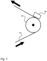
- Fig. 1 illustrates a placement of a capacitor 106 in relation to a web of packaging material 102.
- a suitable placement of the capacitor 106 may be in connection to a roller 104. In this region, vibrations or oscillations of the web 102 are smaller than for instance in between two rollers.
- the capacitor may be curved with the same diameter as the roller 104, so that it can be placed along the bend where the web of packaging material 102 is in contact with the roller 104.
- the arrows indicate the moving direction of the web of packaging material.
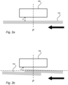
- Fig. 2a illustrates, in a cross-sectional view, the capacitor 106 placed at a distance d from the web of packaging material 102.
- the distance d may be 2-5 mm. How close the capacitor 106 can be placed to the web of packaging material 102 may depend on how much the web vibrates.
- the distance d should be sufficiently large so that the web of packaging material 102 cannot touch the capacitor 106, since this may cause damage either to the capacitor 106 or to the web of packaging material 102.
- the distance d should be sufficiently small so that the web of packaging material 102 is fed through a region where it affects the dielectric properties of the capacitor 106. The closer it is, the more clear the effect is.
- the dielectric properties can be affected by the distance between the web of packaging material 102 and the capacitor 106. It may also be affected by the thickness of the web of material, since a volume of air is replaced by the same volume of packaging material and the packaging material has different dielectric properties than air.
- the distance d may also be dependent on the thickness of the packaging material as illustrated in Fig. 2b.
- Fig. 2b illustrates, in a cross-sectional view, the capacitor 106 placed at the same distance d as in Fig. 2a from the web of packaging material 102.
- a feature, in the form of a splice is present under the capacitor 106, at the position p. Due to how the splice is formed, a part of the web reaches closer to the capacitor 106 than the distance d.
- the web of packaging material 102 is slightly tilted, compared to in Fig. 2a .
- the reason is due to how the splice is formed. When looking at a small region around the splice, this may be a more accurate illustration. Looking at the web of packaging material 102 at a distance, the web 102 is significantly parallel to the capacitor 106 as in Fig. 2a . How the splice is formed and how sections of the web placed next to the splice are affected depend on the packaging material.
- the splice can be the junction between two independent reels of packaging material. Normal operation of packaging machines requires the creation of splices when one of the two reels in the Automatic Splicing Unit, ASU, is about to finish.
- the splice can be a doctoring splice. Such a splice can be formed when a part of the web of packaging material has to be removed. The doctoring splice may then be formed to join the two ends created from removing a part of the web. Thus, the splice appears as a thicker part of the web of packaging material because of the junction between two ends. Measuring the capacitance of the scenario in Fig. 2b may yield a higher value than in the scenario in Fig. 2a , because of the thicker part of the web.
- the increased thickness of the web of packaging material 102 at the splice, due to the overlapping packaging material, may result in the web of packaging material 102 passing the capacitor 106 at a smaller distance than the distance d.
- the dielectric properties may be affected by that the distance d is decreased due to the increased thickness caused by the splice, but also in that more packaging material is provided close to the first capacitor 106, i.e. two layers of packaging material are provided.
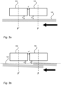
- Fig. 3a and 3b illustrates the two scenarios of Fig. 2a and 2b respectively, but with a second capacitor 302 at position p' in addition to the first capacitor 106 at position p.
- the first and second capacitor 106, 302 are herein placed at the same distance d from the web of packaging material 102. Further, the first and second capacitor 106, 302 is placed at a separational distance d' from each other.
- the separational distance d' may be large enough so that a feature can affect the capacitance of either the first or second capacitor 106, 302 differently.
- the differential capacitance may indicate the presence of a feature in a clear way.
- the separational distance d' may be 10 mm.
- the feature may be detected either at position p, as illustrated herein, or at position p' when the feature has moved upstream.
- Fig. 4 illustrates a different type of feature being detected by the first and second capacitor 106, 302.
- the feature can be an area 402 where material has been added to or removed from the web of packaging material 102.
- the feature is illustrates as an area 402 where material has been removed.
- Such an area 402 may be a pre-laminated hole, PLH, i.e. an area in which a carton layer has been removed.
- the PLH may later be covered by a cap or other opening device
- Another alternative may be folding lines for folding the web 102 into a package.
- the folding lines also sometimes referred to as weakening lines, may be areas in which the packaging material has been compressed. By having these areas, formed as lines, folding of the web can be facilitated and a risk of having unintentional folding can be reduced.
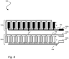
- Fig. 5 illustrates, by way of example, an arrangement 500 comprising the first and the second capacitor 106, 302.
- the first and second capacitors 106, 302 are herein illustrated as interdigital planar capacitors.
- the plates of the interconnected capacitors may have a plurality of sub-plates. Even though illustrated with ten sub-plates each, the number of sub-plates may vary.
- first and second capacitor 106, 302 comprises a first and second plate respectively, that is connected to each other, thus forming a common plate 504.
- the first and second capacitor 106, 302 further comprises a third and fourth plate 502, 506 respectively, so that each capacitor comprises two plates separated by a dielectric medium.
- the dielectric medium of the first and second capacitor 106, 302 can be formed by the volume of the surrounding air and material, such as the web of packaging material 102.
- the common plate 504 may be separated into two plates, one for each capacitor 106, 302.
- the plates can be manufactured as a standard flexible printed circuit board, PCB.
- the first and second capacitor 106, 302 may have a width w corresponding to a width of the feature to be detected, in order to maximize the variation in capacitance caused by the feature.
- the width w may be 10-20 mm, or more preferably, 16 mm.
- Each plate 502, 504, 506 may be provided with a excitation connector 508a-c, for connecting the capacitors to a source of electrical charges.
- having two capacitors makes it possible to determine a differential capacitance.
- the change in capacitance when a feature is present can be in the range of femtofarads.
- removing noise by using the differential capacitance is advantageous, and it makes the method robust to common mode noise, varying distance between the capacitors and the web, movement of the web, different types of packaging material, support structure and roller.
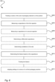
- Fig. 6 is a flow-chart illustrating the steps of a method 600 for detecting and tracking a feature of a web of packaging material 102, using a first capacitor 106 placed at a distance d from the web of packaging material 102.
- a section of the web of packaging material 102 is fed to the first position p, so that the section influences the dielectric property of the first capacitor 106.
- a capacitance of the first capacitor 106 is measured at a point of time t.
- a third step S612 the feature of the section passing the first capacitor 106 at the point of time t is determined, based on the measured capacitance.
- the capacitance of the second capacitor 302 may be measured at the point of time t at a second position p'.
- the second position p' may be located downstream the first position p.
- the capacitance of the first and second capacitor 106, 302 are measured at the same point of time but on different sections of the web. Hence the two capacitors may experience different dielectric mediums.
- a differential capacitance may be determined as a difference between the capacitance of the fist capacitor 106, and the capacitance of the second capacitor 302.
- the step of determining S612 the feature of the section passing the first capacitor 106 at the point of time t may be based on the differential capacitance.
- the step of measuring S604 the capacitance may be performed with the first position p at a roller of a roll fed packaging machine.
- a sixth step S614 the feature is tracked, using the point of time t of the measurement.
- settings of a device of a roll fed packaging machine may be adapted based on the presence of the feature.
- oscillations in the web 102 affecting the distance d between the capacitor 106, 302 and the web 102 may be determined.
- the step of determining S608 the feature may be compensated for the determined oscillations.
- the different steps may also be performed in other orders, as well as multiple times.
- the web of packaging material may be continuously fed past the capacitor, so that features can be detected in any section of the web.
- the method may be repeated at a subsequent point of time t' so that a feature can be detected at a subsequent section of the web.
- the subsequent section of the web may partly overlap with the previous section, depending on the speed of the web, and the length of the time interval between the previous and subsequent point of time.
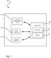
- Fig. 7 is a schematic view of an arrangement 700 for detecting and tracking a feature of a web of packaging material 102 in a roll fed packaging machine.
- the arrangement comprises a first capacitor 702, a capacitor measurement unit 704, a control unit 706 comprising a processor 708 and a memory 710, communicatively connected to the capacitor 702.
- the memory may hold instruction for the processor to execute.
- the control unit is configured to send a request to the capacitance measurement unit 704 to inject a known amount of charges to the first capacitor 702 placed at a distance d from the web of packaging material 102, receive indication that a section of the web of packaging material 102 has been fed to a first position p, so that the section influences a dielectric property of the first capacitor 702, measure, by the capacitor measurement unit 704, at a point of time t, a capacitance of the first capacitor 702, and determine the feature of the section passing the first capacitor 702 at the point of time t, based on the capacitance.
- the arrangement 700 may further comprise a second capacitor 712.
- the control unit 706 may be further configured to measure, by the capacitor measurement unit 704, at the point of time t, a capacitance of the second capacitor 712 at a second position p', wherein the second position p' is located upstream from the first position p, determine a differential capacitance as a difference between the capacitance of the first capacitor 702, and the capacitance of the second capacitor 712, wherein the step of determining the feature of the section passing the first capacitor 702 at the point of time t, is based on the differential capacitance.
- the arrangement may be provided as an update kit to a pre-existing roll fed packaging machine.
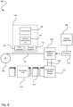
- Fig. 8 is a schematic view of a roll-fed packaging machine 800.
- the roll fed packaging machine 800 is enabled for detecting and tracking the feature of a roll of packaging material 102.
- the roll fed packaging machine 800 can comprise a reel receiver 802 for receiving a reel of packaging material 102, a longitudinal sealing device 804 for forming a tube 806 of the web of packaging material 102, a product filling pipe 808 for filling product 810 into the tube 806, a transversal sealing device 812 for forming packages 814, filled with the product 810, from the tube 806, and an arrangement 700 for detecting and tracking a feature of a web of packaging material in a roll fed packaging machine, as described in connection to Fig. 7 .
- the roll fed packaging machine 800 may be any common roll fed packaging machine provided with the arrangement 700.
- the arrangement may preferably be provided in connection with a roller of the packaging machine, as illustrated in Fig. 1 .
- the arrangement 700 may be installed as an integral part of the machine 800, but it may also be installed as an upgrade kit at a later point of time. Further, even though not illustrated, the arrangement 700 may be connected to a remote server such that program code of the arrangement can be updated if required, and also to provide for that reference data linked to features can be retrieved by the arrangement, thereby making it possible to update the arrangement 700 if e.g. a new type of packaging material is to be used. Further, having the arrangement 700 connected to the remote server, data can be collected and combined with similar data retrieved from other similar arrangements. By doing so, the reference data can be continuously improved by using e.g. ML or Al algorithms.
- the roll fed packaging machine 800 may further comprise a discarding unit 816 for discarding certain packages. For instance, in case the ASU splice or the doctoring splice is detected in the web, this may be traced through the machine. The package formed from the web and that comprise the ASU splice or the doctoring splice may be discarded. To be on the safe side, a number of packages before and after this package may also be discarded. With an increased traceability made possible by the arrangement 700, a number of discarded packages may be reduced.
- the control unit 706 is communicatively connected to a control system of the roll fed packaging machine 800 such that the feature is tracked throughout the roll-fed packaging machine 800. Further, the control system of the roll fed packaging machine 800 is configured to adapt settings of one or more devices of the roll fed packaging machine 800 based on the feature being tracked. As an example, if a splice is present in a package, more power may be provided for the longitudinal sealing. Having two layers of packaging material instead of only one layer may namely require more power, i.e. additional heating, to provide for that a reliable sealing is made. Put differently, if the machine knows when the splice is present, it may alter settings of the longitudinal sealing device 804 to compensate for this.
- packages 814 comprising the splice may have to be discarded due to food safety reasons.
- a common practice is to also discard one package before and one package after the package comprising the splice. Again, by tracking the splice, the discarding unit 816 can know what packages 814 to discard.
Landscapes
- Engineering & Computer Science (AREA)
- Mechanical Engineering (AREA)
- Physics & Mathematics (AREA)
- General Physics & Mathematics (AREA)
- Controlling Rewinding, Feeding, Winding, Or Abnormalities Of Webs (AREA)
- Containers And Plastic Fillers For Packaging (AREA)
- Investigating Or Analyzing Materials By The Use Of Electric Means (AREA)
- Measurement Of Length, Angles, Or The Like Using Electric Or Magnetic Means (AREA)
Claims (11)
- Procédé (600) destiné à détecter et suivre une caractéristique d'une bande de matériau d'emballage (102), au moyen d'un premier condensateur (106) placé à une distance (d) de la bande de matériau d'emballage (102), le procédé (600) comprenant :l'avance (S602) d'une section de la bande de matériau d'emballage (102) jusqu'à une première position (p), de telle sorte que la section influence une propriété diélectrique du premier condensateur (106),la mesure (S604), à un instant (t), d'une capacité du premier condensateur (106),la détermination (S612) de la caractéristique de la section passant le premier condensateur (106) à l'instant (t), sur la base de la capacité,le suivi (S614) de la caractéristique, au moyen de l'instant (t) de la mesure, etl'adaptation (S616) de réglages d'un dispositif d'une machine d'emballage à avance par rouleaux sur la base de la présence de la caractéristique.
- Procédé (600) selon la revendication 1, le procédé (600) comprenant en outre :la mesure (S606), à l'instant (t), d'une capacité d'un deuxième condensateur (302) à une deuxième position (p'), la deuxième position (p') étant située en aval de la première position (p),la détermination (S608) d'une capacité différentielle comme une différence entre la capacité du premier condensateur (106) et la capacité du deuxième condensateur (302),dans lequel l'étape de détermination (S612) de la caractéristique de la section passant le premier condensateur (106) à l'instant (t) est basée sur la capacité différentielle.
- Procédé (600) selon la revendication 2, dans lequel une première plaque de condensateur du premier condensateur (106) est reliée à une deuxième plaque de condensateur du deuxième condensateur (302).
- Procédé (600) selon l'une quelconque des revendications précédentes, dans lequel un rouleau de la machine d'emballage à avance par rouleaux est placé en face du premier condensateur et l'étape de mesure (S604) de la capacité est effectuée avec la bande en contact avec le rouleau.
- Procédé (600) selon l'une quelconque des revendications précédentes, le procédé (600) comprenant en outre :la détermination (S610) d'oscillations dans la bande (102) affectant la distance (d) entre le condensateur (106, 302) et la bande (102),la compensation des oscillations à l'étape de détermination (S608) de la caractéristique.
- Procédé (600) selon l'une quelconque des revendications précédentes, dans lequel la distance (d) entre le condensateur (106, 302) et la bande de matériau d'emballage (102) est de 2-5 mm.
- Procédé (600) selon l'une quelconque des revendications précédentes, dans lequel le condensateur (106, 302) est un condensateur plan.
- Procédé (600) selon l'une quelconque des revendications précédentes, dans lequel la caractéristique est liée à une épaisseur de la bande de matériau d'emballage (102).
- Procédé (600) selon l'une quelconque des revendications précédentes, dans lequel la caractéristique est un raccord entre deux extrémités de matériau d'emballage.
- Procédé (600) selon l'une quelconque des revendications précédentes, dans lequel la caractéristique est une zone (402) ou un matériau a été ajouté à ou retiré de la bande de matériau d'emballage.
- Machine d'emballage à avance par rouleaux (800) comprenant :un récepteur de bobine (802) destiné à recevoir un rouleau de matériau d'emballage (102),un dispositif de scellement longitudinal (804) destiné à former un tube (806) de la bande de matériau d'emballage (102),un tuyau de remplissage de produit (808) destiné à remplir avec un produit (810) l'intérieur du tube (806),un dispositif de scellement transversal (812) destiné à former des emballages (814), remplis avec le produit (810), à partir du tube (806),un agencement (700) destiné à détecter et suivre une caractéristique d'une bande de matériau d'emballage dans une machine d'emballage à avance par rouleaux comprenant :un premier condensateur (702),une unité de mesure de condensateur (704),une unité de commande (706) comprenant un processeur (708) et une mémoire (710), reliée de façon communicante au condensateur (702), l'unité de commande (706) étant configurée pour :envoyer une requête à l'unité de mesure de capacité pour injecter une quantité connue de charges dans le premier condensateur (702) placé à une distance (d) de la bande de matériau d'emballage (102),recevoir une indication qu'une section de la bande de matériau d'emballage (102) a été avancée jusqu'à une première position (p), de telle sorte que la section influence une propriété diélectrique du premier condensateur (702),faire mesurer, par l'unité de mesure de condensateur, à un instant (t), une capacité du premier condensateur (702), etdéterminer la caractéristique de la section passant le premier condensateur (702) à l'instant (t), sur la base de la capacité, dans laquelle l'unité de commande (706) est reliée de façon communicante à un système de commande de la machine d'emballage à avance par rouleaux de telle sorte que la caractéristique est suivie d'un bout à l'autre de la machine d'emballage à avance par rouleaux, etdans laquelle le système de commande de la machine d'emballage à avance par rouleaux est configuré pour adapter des réglages d'un ou plusieurs dispositifs de la machine d'emballage à avance par rouleaux sur la base de la caractéristique suivie.
Applications Claiming Priority (1)
| Application Number | Priority Date | Filing Date | Title |
|---|---|---|---|
| EP20210988 | 2020-12-01 |
Publications (2)
| Publication Number | Publication Date |
|---|---|
| EP4008657A1 EP4008657A1 (fr) | 2022-06-08 |
| EP4008657B1 true EP4008657B1 (fr) | 2024-03-20 |
Family
ID=73654724
Family Applications (1)
| Application Number | Title | Priority Date | Filing Date |
|---|---|---|---|
| EP21210405.3A Active EP4008657B1 (fr) | 2020-12-01 | 2021-11-25 | Procédé de détection et de suivi d'une caractéristique d'une bande de matériau d'emballage |
Country Status (5)
| Country | Link |
|---|---|
| US (1) | US12404062B2 (fr) |
| EP (1) | EP4008657B1 (fr) |
| JP (1) | JP2023551064A (fr) |
| CN (1) | CN116507875A (fr) |
| WO (1) | WO2022117425A1 (fr) |
Families Citing this family (1)
| Publication number | Priority date | Publication date | Assignee | Title |
|---|---|---|---|---|
| WO2025140873A1 (fr) * | 2023-12-27 | 2025-07-03 | Tetra Laval Holdings & Finance S.A. | Machine d'emballage pour la production d'emballages scellés à partir d'une bande de matériau d'emballage |
Family Cites Families (16)
| Publication number | Priority date | Publication date | Assignee | Title |
|---|---|---|---|---|
| US3519922A (en) * | 1965-12-16 | 1970-07-07 | Nash & Harrison Ltd | Apparatus for detecting abrupt change in the thickness of sheet material |
| US4276547A (en) * | 1977-12-22 | 1981-06-30 | Research Technology, Inc. | Film thickness detection system |
| JP3580372B2 (ja) * | 1993-12-17 | 2004-10-20 | 株式会社イシダ | 包装機における継目部分の包装物排除装置 |
| JP3479824B2 (ja) * | 1996-08-23 | 2003-12-15 | 松下電工株式会社 | 静電容量型タッチスイッチ |
| CH695250A5 (de) * | 2000-05-03 | 2006-02-15 | Leuze Electronic Gmbh & Co | Vorrichtung zur Detektion von Marken auf einer Materialbahn. |
| ITBO20010079A1 (it) * | 2001-02-14 | 2002-08-14 | Gd Spa | Metodo e dispositivo per il controllo di materiale di incarto in una macchina confezionatrice |
| SE531047C2 (sv) * | 2005-03-02 | 2008-12-02 | Tetra Laval Holdings & Finance | System och sätt för att tillverka ett förpackningslaminat samt förpackningsbehållare som tillverkas från förpackningslaminatet |
| JP4755283B2 (ja) * | 2007-07-26 | 2011-08-24 | 富士通株式会社 | 紙葉厚み検出装置 |
| JP5315529B2 (ja) * | 2009-03-24 | 2013-10-16 | 株式会社フジクラ | 静電容量型近接センサ、近接検知方法および静電容量型近接センサの電極構造 |
| JP5970777B2 (ja) * | 2011-10-31 | 2016-08-17 | キョーラク株式会社 | 包装体及びその製造方法 |
| CN203811121U (zh) * | 2014-04-29 | 2014-09-03 | 威海华菱光电股份有限公司 | 厚度传感器 |
| CN103968749A (zh) * | 2014-05-16 | 2014-08-06 | 威海华菱光电股份有限公司 | 物体厚度检测装置及其检测方法 |
| CN204400259U (zh) * | 2014-12-30 | 2015-06-17 | 江苏立富电极箔有限公司 | 一种连续接箔装置 |
| AU2016267216C1 (en) * | 2015-05-26 | 2019-06-06 | Ishida Co., Ltd. | Production Line Configuration Apparatus |
| CN106501340B (zh) * | 2016-09-23 | 2019-07-09 | 上海小海龟科技有限公司 | 电极、离子敏感传感器、电容和离子活度的检测方法 |
| US11614317B2 (en) * | 2019-06-21 | 2023-03-28 | Tyrata, Inc. | Methods providing enhanced material thickness sensing with capacitive sensors using inductance-generated resonance and related devices |
-
2021
- 2021-11-25 EP EP21210405.3A patent/EP4008657B1/fr active Active
- 2021-11-25 US US18/254,570 patent/US12404062B2/en active Active
- 2021-11-25 JP JP2023533324A patent/JP2023551064A/ja active Pending
- 2021-11-25 WO PCT/EP2021/082958 patent/WO2022117425A1/fr not_active Ceased
- 2021-11-25 CN CN202180079894.6A patent/CN116507875A/zh active Pending
Also Published As
| Publication number | Publication date |
|---|---|
| US12404062B2 (en) | 2025-09-02 |
| WO2022117425A1 (fr) | 2022-06-09 |
| JP2023551064A (ja) | 2023-12-06 |
| CN116507875A (zh) | 2023-07-28 |
| EP4008657A1 (fr) | 2022-06-08 |
| US20240017867A1 (en) | 2024-01-18 |
Similar Documents
| Publication | Publication Date | Title |
|---|---|---|
| JP4755283B2 (ja) | 紙葉厚み検出装置 | |
| EP4008657B1 (fr) | Procédé de détection et de suivi d'une caractéristique d'une bande de matériau d'emballage | |
| KR20070109858A (ko) | 피복층의 두께계량기구 및 그것을 이용한 피복층형성장치 | |
| US6988398B2 (en) | Method and device for tracking the edge of a web | |
| KR102375416B1 (ko) | 저항 측정 장치, 필름 제조 장치 및 도전성 필름의 제조 방법 | |
| US5778724A (en) | Method and device for monitoring web bagginess | |
| CN102722933A (zh) | 一种薄片类介质厚度检测装置及其方法 | |
| CN108357153B (zh) | 瓦楞纸板设备和用于生产瓦楞纸板片的方法 | |
| KR20230026865A (ko) | 전극 파단시의 롤맵 좌표 보정시스템 및 롤맵 좌표 보정방법 | |
| CN107430795B (zh) | 纸张厚度检测传感器及纸币鉴别单元 | |
| KR20040025745A (ko) | 부품 벨트를 검출하기 위한 센서를 구비한 부품 공급 장치 및 부품 벨트를 검출하기 위한 방법 | |
| US6508138B1 (en) | Method of, and device for, checking cigarettes | |
| US10246826B2 (en) | Method for operating a machine for producing and/or processing a material web | |
| CN109532118A (zh) | 接纸控制方法、装置及生产管理系统 | |
| KR101618641B1 (ko) | 볼트 불량검출기 | |
| JP7725770B2 (ja) | 電極シートカッティング装置及びカッティング方法 | |
| CN107421451A (zh) | 基于w型监测点布局的宽幅传感检测装置及纠偏控制系统 | |
| US20120260813A1 (en) | Method and device for measuring a running direction of a substrate web | |
| EP4563508A1 (fr) | Procédé de surveillance d'un agencement de manipulation de bande | |
| US20200369476A1 (en) | Sensor device for recognizing consecutive objects | |
| JP2010105772A (ja) | コルゲータの紙継ぎ部検出装置及び方法並びに紙継ぎ部除去装置付きコルゲータ | |
| CN118974513A (zh) | 表面形状测定装置、表面形状测定方法以及带的管理方法 | |
| EP4481519A1 (fr) | Surveillance automatisée d'alignement intercadre pour applications de fabrication de feuilles | |
| EP4711118A1 (fr) | Machine d'emballage pour produire des emballages scellés à partir d'une bande de matériau d'emballage, procédé correspondant et produit de programme informatique | |
| CN214566644U (zh) | 商标纸下纸通道堵塞检测装置及卷烟包装机 |
Legal Events
| Date | Code | Title | Description |
|---|---|---|---|
| PUAI | Public reference made under article 153(3) epc to a published international application that has entered the european phase |
Free format text: ORIGINAL CODE: 0009012 |
|
| STAA | Information on the status of an ep patent application or granted ep patent |
Free format text: STATUS: THE APPLICATION HAS BEEN PUBLISHED |
|
| AK | Designated contracting states |
Kind code of ref document: A1 Designated state(s): AL AT BE BG CH CY CZ DE DK EE ES FI FR GB GR HR HU IE IS IT LI LT LU LV MC MK MT NL NO PL PT RO RS SE SI SK SM TR |
|
| STAA | Information on the status of an ep patent application or granted ep patent |
Free format text: STATUS: REQUEST FOR EXAMINATION WAS MADE |
|
| 17P | Request for examination filed |
Effective date: 20221208 |
|
| RBV | Designated contracting states (corrected) |
Designated state(s): AL AT BE BG CH CY CZ DE DK EE ES FI FR GB GR HR HU IE IS IT LI LT LU LV MC MK MT NL NO PL PT RO RS SE SI SK SM TR |
|
| GRAP | Despatch of communication of intention to grant a patent |
Free format text: ORIGINAL CODE: EPIDOSNIGR1 |
|
| STAA | Information on the status of an ep patent application or granted ep patent |
Free format text: STATUS: GRANT OF PATENT IS INTENDED |
|
| INTG | Intention to grant announced |
Effective date: 20231116 |
|
| GRAS | Grant fee paid |
Free format text: ORIGINAL CODE: EPIDOSNIGR3 |
|
| GRAA | (expected) grant |
Free format text: ORIGINAL CODE: 0009210 |
|
| STAA | Information on the status of an ep patent application or granted ep patent |
Free format text: STATUS: THE PATENT HAS BEEN GRANTED |
|
| AK | Designated contracting states |
Kind code of ref document: B1 Designated state(s): AL AT BE BG CH CY CZ DE DK EE ES FI FR GB GR HR HU IE IS IT LI LT LU LV MC MK MT NL NO PL PT RO RS SE SI SK SM TR |
|
| REG | Reference to a national code |
Ref country code: GB Ref legal event code: FG4D |
|
| REG | Reference to a national code |
Ref country code: CH Ref legal event code: EP |
|
| REG | Reference to a national code |
Ref country code: IE Ref legal event code: FG4D |
|
| REG | Reference to a national code |
Ref country code: DE Ref legal event code: R096 Ref document number: 602021010634 Country of ref document: DE |
|
| P01 | Opt-out of the competence of the unified patent court (upc) registered |
Effective date: 20240404 |
|
| PG25 | Lapsed in a contracting state [announced via postgrant information from national office to epo] |
Ref country code: LT Free format text: LAPSE BECAUSE OF FAILURE TO SUBMIT A TRANSLATION OF THE DESCRIPTION OR TO PAY THE FEE WITHIN THE PRESCRIBED TIME-LIMIT Effective date: 20240320 |
|
| REG | Reference to a national code |
Ref country code: LT Ref legal event code: MG9D |
|
| PG25 | Lapsed in a contracting state [announced via postgrant information from national office to epo] |
Ref country code: GR Free format text: LAPSE BECAUSE OF FAILURE TO SUBMIT A TRANSLATION OF THE DESCRIPTION OR TO PAY THE FEE WITHIN THE PRESCRIBED TIME-LIMIT Effective date: 20240621 |
|
| PG25 | Lapsed in a contracting state [announced via postgrant information from national office to epo] |
Ref country code: HR Free format text: LAPSE BECAUSE OF FAILURE TO SUBMIT A TRANSLATION OF THE DESCRIPTION OR TO PAY THE FEE WITHIN THE PRESCRIBED TIME-LIMIT Effective date: 20240320 Ref country code: RS Free format text: LAPSE BECAUSE OF FAILURE TO SUBMIT A TRANSLATION OF THE DESCRIPTION OR TO PAY THE FEE WITHIN THE PRESCRIBED TIME-LIMIT Effective date: 20240620 |
|
| REG | Reference to a national code |
Ref country code: NL Ref legal event code: MP Effective date: 20240320 |
|
| PG25 | Lapsed in a contracting state [announced via postgrant information from national office to epo] |
Ref country code: RS Free format text: LAPSE BECAUSE OF FAILURE TO SUBMIT A TRANSLATION OF THE DESCRIPTION OR TO PAY THE FEE WITHIN THE PRESCRIBED TIME-LIMIT Effective date: 20240620 Ref country code: NO Free format text: LAPSE BECAUSE OF FAILURE TO SUBMIT A TRANSLATION OF THE DESCRIPTION OR TO PAY THE FEE WITHIN THE PRESCRIBED TIME-LIMIT Effective date: 20240620 Ref country code: LT Free format text: LAPSE BECAUSE OF FAILURE TO SUBMIT A TRANSLATION OF THE DESCRIPTION OR TO PAY THE FEE WITHIN THE PRESCRIBED TIME-LIMIT Effective date: 20240320 Ref country code: HR Free format text: LAPSE BECAUSE OF FAILURE TO SUBMIT A TRANSLATION OF THE DESCRIPTION OR TO PAY THE FEE WITHIN THE PRESCRIBED TIME-LIMIT Effective date: 20240320 Ref country code: GR Free format text: LAPSE BECAUSE OF FAILURE TO SUBMIT A TRANSLATION OF THE DESCRIPTION OR TO PAY THE FEE WITHIN THE PRESCRIBED TIME-LIMIT Effective date: 20240621 Ref country code: FI Free format text: LAPSE BECAUSE OF FAILURE TO SUBMIT A TRANSLATION OF THE DESCRIPTION OR TO PAY THE FEE WITHIN THE PRESCRIBED TIME-LIMIT Effective date: 20240320 Ref country code: BG Free format text: LAPSE BECAUSE OF FAILURE TO SUBMIT A TRANSLATION OF THE DESCRIPTION OR TO PAY THE FEE WITHIN THE PRESCRIBED TIME-LIMIT Effective date: 20240320 |
|
| REG | Reference to a national code |
Ref country code: AT Ref legal event code: MK05 Ref document number: 1667668 Country of ref document: AT Kind code of ref document: T Effective date: 20240320 |
|
| PG25 | Lapsed in a contracting state [announced via postgrant information from national office to epo] |
Ref country code: SE Free format text: LAPSE BECAUSE OF FAILURE TO SUBMIT A TRANSLATION OF THE DESCRIPTION OR TO PAY THE FEE WITHIN THE PRESCRIBED TIME-LIMIT Effective date: 20240320 Ref country code: LV Free format text: LAPSE BECAUSE OF FAILURE TO SUBMIT A TRANSLATION OF THE DESCRIPTION OR TO PAY THE FEE WITHIN THE PRESCRIBED TIME-LIMIT Effective date: 20240320 |
|
| PG25 | Lapsed in a contracting state [announced via postgrant information from national office to epo] |
Ref country code: NL Free format text: LAPSE BECAUSE OF FAILURE TO SUBMIT A TRANSLATION OF THE DESCRIPTION OR TO PAY THE FEE WITHIN THE PRESCRIBED TIME-LIMIT Effective date: 20240320 |
|
| PG25 | Lapsed in a contracting state [announced via postgrant information from national office to epo] |
Ref country code: NL Free format text: LAPSE BECAUSE OF FAILURE TO SUBMIT A TRANSLATION OF THE DESCRIPTION OR TO PAY THE FEE WITHIN THE PRESCRIBED TIME-LIMIT Effective date: 20240320 |
|
| PG25 | Lapsed in a contracting state [announced via postgrant information from national office to epo] |
Ref country code: IS Free format text: LAPSE BECAUSE OF FAILURE TO SUBMIT A TRANSLATION OF THE DESCRIPTION OR TO PAY THE FEE WITHIN THE PRESCRIBED TIME-LIMIT Effective date: 20240720 |
|
| PG25 | Lapsed in a contracting state [announced via postgrant information from national office to epo] |
Ref country code: PT Free format text: LAPSE BECAUSE OF FAILURE TO SUBMIT A TRANSLATION OF THE DESCRIPTION OR TO PAY THE FEE WITHIN THE PRESCRIBED TIME-LIMIT Effective date: 20240722 Ref country code: SM Free format text: LAPSE BECAUSE OF FAILURE TO SUBMIT A TRANSLATION OF THE DESCRIPTION OR TO PAY THE FEE WITHIN THE PRESCRIBED TIME-LIMIT Effective date: 20240320 |
|
| PG25 | Lapsed in a contracting state [announced via postgrant information from national office to epo] |
Ref country code: ES Free format text: LAPSE BECAUSE OF FAILURE TO SUBMIT A TRANSLATION OF THE DESCRIPTION OR TO PAY THE FEE WITHIN THE PRESCRIBED TIME-LIMIT Effective date: 20240320 |
|
| PG25 | Lapsed in a contracting state [announced via postgrant information from national office to epo] |
Ref country code: EE Free format text: LAPSE BECAUSE OF FAILURE TO SUBMIT A TRANSLATION OF THE DESCRIPTION OR TO PAY THE FEE WITHIN THE PRESCRIBED TIME-LIMIT Effective date: 20240320 Ref country code: CZ Free format text: LAPSE BECAUSE OF FAILURE TO SUBMIT A TRANSLATION OF THE DESCRIPTION OR TO PAY THE FEE WITHIN THE PRESCRIBED TIME-LIMIT Effective date: 20240320 |
|
| PG25 | Lapsed in a contracting state [announced via postgrant information from national office to epo] |
Ref country code: AT Free format text: LAPSE BECAUSE OF FAILURE TO SUBMIT A TRANSLATION OF THE DESCRIPTION OR TO PAY THE FEE WITHIN THE PRESCRIBED TIME-LIMIT Effective date: 20240320 |
|
| PG25 | Lapsed in a contracting state [announced via postgrant information from national office to epo] |
Ref country code: PL Free format text: LAPSE BECAUSE OF FAILURE TO SUBMIT A TRANSLATION OF THE DESCRIPTION OR TO PAY THE FEE WITHIN THE PRESCRIBED TIME-LIMIT Effective date: 20240320 |
|
| PG25 | Lapsed in a contracting state [announced via postgrant information from national office to epo] |
Ref country code: SK Free format text: LAPSE BECAUSE OF FAILURE TO SUBMIT A TRANSLATION OF THE DESCRIPTION OR TO PAY THE FEE WITHIN THE PRESCRIBED TIME-LIMIT Effective date: 20240320 |
|
| PG25 | Lapsed in a contracting state [announced via postgrant information from national office to epo] |
Ref country code: SM Free format text: LAPSE BECAUSE OF FAILURE TO SUBMIT A TRANSLATION OF THE DESCRIPTION OR TO PAY THE FEE WITHIN THE PRESCRIBED TIME-LIMIT Effective date: 20240320 Ref country code: SK Free format text: LAPSE BECAUSE OF FAILURE TO SUBMIT A TRANSLATION OF THE DESCRIPTION OR TO PAY THE FEE WITHIN THE PRESCRIBED TIME-LIMIT Effective date: 20240320 Ref country code: RO Free format text: LAPSE BECAUSE OF FAILURE TO SUBMIT A TRANSLATION OF THE DESCRIPTION OR TO PAY THE FEE WITHIN THE PRESCRIBED TIME-LIMIT Effective date: 20240320 Ref country code: PT Free format text: LAPSE BECAUSE OF FAILURE TO SUBMIT A TRANSLATION OF THE DESCRIPTION OR TO PAY THE FEE WITHIN THE PRESCRIBED TIME-LIMIT Effective date: 20240722 Ref country code: PL Free format text: LAPSE BECAUSE OF FAILURE TO SUBMIT A TRANSLATION OF THE DESCRIPTION OR TO PAY THE FEE WITHIN THE PRESCRIBED TIME-LIMIT Effective date: 20240320 Ref country code: IS Free format text: LAPSE BECAUSE OF FAILURE TO SUBMIT A TRANSLATION OF THE DESCRIPTION OR TO PAY THE FEE WITHIN THE PRESCRIBED TIME-LIMIT Effective date: 20240720 Ref country code: ES Free format text: LAPSE BECAUSE OF FAILURE TO SUBMIT A TRANSLATION OF THE DESCRIPTION OR TO PAY THE FEE WITHIN THE PRESCRIBED TIME-LIMIT Effective date: 20240320 Ref country code: EE Free format text: LAPSE BECAUSE OF FAILURE TO SUBMIT A TRANSLATION OF THE DESCRIPTION OR TO PAY THE FEE WITHIN THE PRESCRIBED TIME-LIMIT Effective date: 20240320 Ref country code: CZ Free format text: LAPSE BECAUSE OF FAILURE TO SUBMIT A TRANSLATION OF THE DESCRIPTION OR TO PAY THE FEE WITHIN THE PRESCRIBED TIME-LIMIT Effective date: 20240320 Ref country code: AT Free format text: LAPSE BECAUSE OF FAILURE TO SUBMIT A TRANSLATION OF THE DESCRIPTION OR TO PAY THE FEE WITHIN THE PRESCRIBED TIME-LIMIT Effective date: 20240320 |
|
| REG | Reference to a national code |
Ref country code: DE Ref legal event code: R097 Ref document number: 602021010634 Country of ref document: DE |
|
| PG25 | Lapsed in a contracting state [announced via postgrant information from national office to epo] |
Ref country code: DK Free format text: LAPSE BECAUSE OF FAILURE TO SUBMIT A TRANSLATION OF THE DESCRIPTION OR TO PAY THE FEE WITHIN THE PRESCRIBED TIME-LIMIT Effective date: 20240320 |
|
| PLBE | No opposition filed within time limit |
Free format text: ORIGINAL CODE: 0009261 |
|
| STAA | Information on the status of an ep patent application or granted ep patent |
Free format text: STATUS: NO OPPOSITION FILED WITHIN TIME LIMIT |
|
| PG25 | Lapsed in a contracting state [announced via postgrant information from national office to epo] |
Ref country code: DK Free format text: LAPSE BECAUSE OF FAILURE TO SUBMIT A TRANSLATION OF THE DESCRIPTION OR TO PAY THE FEE WITHIN THE PRESCRIBED TIME-LIMIT Effective date: 20240320 |
|
| 26N | No opposition filed |
Effective date: 20241223 |
|
| PG25 | Lapsed in a contracting state [announced via postgrant information from national office to epo] |
Ref country code: SI Free format text: LAPSE BECAUSE OF FAILURE TO SUBMIT A TRANSLATION OF THE DESCRIPTION OR TO PAY THE FEE WITHIN THE PRESCRIBED TIME-LIMIT Effective date: 20240320 |
|
| REG | Reference to a national code |
Ref country code: CH Ref legal event code: PL |
|
| PG25 | Lapsed in a contracting state [announced via postgrant information from national office to epo] |
Ref country code: MC Free format text: LAPSE BECAUSE OF FAILURE TO SUBMIT A TRANSLATION OF THE DESCRIPTION OR TO PAY THE FEE WITHIN THE PRESCRIBED TIME-LIMIT Effective date: 20240320 |
|
| PG25 | Lapsed in a contracting state [announced via postgrant information from national office to epo] |
Ref country code: LU Free format text: LAPSE BECAUSE OF NON-PAYMENT OF DUE FEES Effective date: 20241125 |
|
| REG | Reference to a national code |
Ref country code: CH Ref legal event code: PL |
|
| PG25 | Lapsed in a contracting state [announced via postgrant information from national office to epo] |
Ref country code: CH Free format text: LAPSE BECAUSE OF NON-PAYMENT OF DUE FEES Effective date: 20241130 |
|
| REG | Reference to a national code |
Ref country code: BE Ref legal event code: MM Effective date: 20241130 |
|
| PG25 | Lapsed in a contracting state [announced via postgrant information from national office to epo] |
Ref country code: BE Free format text: LAPSE BECAUSE OF NON-PAYMENT OF DUE FEES Effective date: 20241130 |
|
| PG25 | Lapsed in a contracting state [announced via postgrant information from national office to epo] |
Ref country code: FR Free format text: LAPSE BECAUSE OF NON-PAYMENT OF DUE FEES Effective date: 20241130 |
|
| PG25 | Lapsed in a contracting state [announced via postgrant information from national office to epo] |
Ref country code: IE Free format text: LAPSE BECAUSE OF NON-PAYMENT OF DUE FEES Effective date: 20241125 |
|
| PGFP | Annual fee paid to national office [announced via postgrant information from national office to epo] |
Ref country code: DE Payment date: 20251126 Year of fee payment: 5 |
|
| PGFP | Annual fee paid to national office [announced via postgrant information from national office to epo] |
Ref country code: IT Payment date: 20251121 Year of fee payment: 5 |
|
| PG25 | Lapsed in a contracting state [announced via postgrant information from national office to epo] |
Ref country code: HU Free format text: LAPSE BECAUSE OF FAILURE TO SUBMIT A TRANSLATION OF THE DESCRIPTION OR TO PAY THE FEE WITHIN THE PRESCRIBED TIME-LIMIT; INVALID AB INITIO Effective date: 20211125 |