EP4008664B1 - Verfahren zur verhinderung von schwerkraftsprüngen bei einem notstopp in aufzugssystemen - Google Patents
Verfahren zur verhinderung von schwerkraftsprüngen bei einem notstopp in aufzugssystemen Download PDFInfo
- Publication number
- EP4008664B1 EP4008664B1 EP20212046.5A EP20212046A EP4008664B1 EP 4008664 B1 EP4008664 B1 EP 4008664B1 EP 20212046 A EP20212046 A EP 20212046A EP 4008664 B1 EP4008664 B1 EP 4008664B1
- Authority
- EP
- European Patent Office
- Prior art keywords
- emergency stop
- delay
- brake device
- drive
- elevator car
- Prior art date
- Legal status (The legal status is an assumption and is not a legal conclusion. Google has not performed a legal analysis and makes no representation as to the accuracy of the status listed.)
- Active
Links
Images

Classifications
-
- B—PERFORMING OPERATIONS; TRANSPORTING
- B66—HOISTING; LIFTING; HAULING
- B66B—ELEVATORS; ESCALATORS OR MOVING WALKWAYS
- B66B5/00—Applications of checking, fault-correcting, or safety devices in elevators
- B66B5/02—Applications of checking, fault-correcting, or safety devices in elevators responsive to abnormal operating conditions
-
- B—PERFORMING OPERATIONS; TRANSPORTING
- B66—HOISTING; LIFTING; HAULING
- B66B—ELEVATORS; ESCALATORS OR MOVING WALKWAYS
- B66B1/00—Control systems of elevators in general
- B66B1/24—Control systems with regulation, i.e. with retroactive action, for influencing travelling speed, acceleration, or deceleration
- B66B1/28—Control systems with regulation, i.e. with retroactive action, for influencing travelling speed, acceleration, or deceleration electrical
- B66B1/32—Control systems with regulation, i.e. with retroactive action, for influencing travelling speed, acceleration, or deceleration electrical effective on braking devices, e.g. acting on electrically controlled brakes
-
- B—PERFORMING OPERATIONS; TRANSPORTING
- B66—HOISTING; LIFTING; HAULING
- B66B—ELEVATORS; ESCALATORS OR MOVING WALKWAYS
- B66B5/00—Applications of checking, fault-correcting, or safety devices in elevators
- B66B5/0006—Monitoring devices or performance analysers
- B66B5/0018—Devices monitoring the operating condition of the elevator system
- B66B5/0031—Devices monitoring the operating condition of the elevator system for safety reasons
-
- B—PERFORMING OPERATIONS; TRANSPORTING
- B66—HOISTING; LIFTING; HAULING
- B66B—ELEVATORS; ESCALATORS OR MOVING WALKWAYS
- B66B5/00—Applications of checking, fault-correcting, or safety devices in elevators
- B66B5/02—Applications of checking, fault-correcting, or safety devices in elevators responsive to abnormal operating conditions
- B66B5/027—Applications of checking, fault-correcting, or safety devices in elevators responsive to abnormal operating conditions to permit passengers to leave an elevator car in case of failure, e.g. moving the car to a reference floor or unlocking the door
-
- B—PERFORMING OPERATIONS; TRANSPORTING
- B66—HOISTING; LIFTING; HAULING
- B66B—ELEVATORS; ESCALATORS OR MOVING WALKWAYS
- B66B5/00—Applications of checking, fault-correcting, or safety devices in elevators
- B66B5/28—Buffer-stops for cars, cages, or skips
-
- B—PERFORMING OPERATIONS; TRANSPORTING
- B66—HOISTING; LIFTING; HAULING
- B66B—ELEVATORS; ESCALATORS OR MOVING WALKWAYS
- B66B9/00—Kinds or types of lifts in, or associated with, buildings or other structures
Definitions
- the present disclosure relates to elevator systems and methods of controlling an elevator car, in particular upon detecting an emergency stop condition.
- Typical elevator systems comprise one or more elevator cars running in a hoistway to transport passengers or cargo between floors of a building.
- a drive system is controlled to drive the elevator car between the floors (e.g. using a drive device connected to a drive sheave that engages a tension member from which the elevator car is suspended).
- the drive system typically also includes one or more brake devices for decelerating the elevator car (e.g. by applying braking force to the drive sheave).
- elevator systems normally feature a safety chain made up of several electronic relays connected in series and controlled by respective sensors such as hoistway door sensors or overspeed sensors.
- the safety chain controls the supply of power to the drive system. If any unsafe condition (such as an open hoistway door) is detected by one of the sensors, the corresponding relay opens, breaking the safety chain and triggering an emergency stop of the elevator car by cutting power to the drive system. Driving force is removed and the brakes are applied, quickly slowing the car to a halt.
- an emergency stop condition automatically interrupts the power supply to the whole drive system including the drive and brake devices.
- brake devices in elevator systems cannot produce braking force instantly, e.g. due to the time it takes a brake shoe to physically move into full engagement. This is known as a "brake-drop delay".
- the removal of driving force once the power supply to a drive device is interrupted can be very quick.
- no drive force and little or no braking force may be applied to the elevator car. This can result in a "gravity jump", in which the elevator car is actually free to accelerate for a short period of time immediately after an emergency stop is triggered.
- US 2016/0152440 which shows the preamble of claim 1, discloses a braking method for a passenger transportation system.
- An activation signal activates a service brake of the passenger transportation system and an emergency stop is initiated.
- the brake control switches a drive machine of the passenger transportation system into a motor-brake operating mode.
- the drive machine is only switched by the brake control into a braking-torque-free state when a braking effect of the service brake on moving components of the passenger transportation system is detected and transmitted to the brake control.
- WO 2016/156658 discloses a brake control sequence when emergency stop of an elevator is issued. The elevator brakes are applied as soon as possible for stopping movement of an elevator car.
- EP 3457555 discloses a transport conveyor drive featuring a first safety interface 12a and a second safety interface 12b.
- a first safety signal 12a on the first safety interface 12a goes to OFF/LOW with a delay compared to the second safety signal so as to keep the drive motor operating during brake applying delay of the first brake 28a.
- the drive device continues to drive the elevator car for at least some of the time between triggering the brake device and substantive braking force actually being generated (i.e. during a brake drop delay experienced by the brake device).
- gravity jumps are at least partially mitigated, improving ride comfort and convenience and reducing the likelihood of controller errors.
- the drive device is stopped after the determined time period, rather than continuing to operate indefinitely, it is less likely to oppose braking force eventually generated by the brake device for a significant amount of time. This reduces the likelihood of excessive brake wear or even failures of the brake device and/or the drive device.
- the drive device continues to drive the elevator car after triggering the brake device, the acceleration of the elevator car during the delay may be lower compared to the acceleration experienced during a gravity jump, meaning that the elevator car does not travel as far before the brakes are engaged and the emergency stop may therefore be carried out over a shorter distance. This may allow for higher operating speeds and/or tighter operational margins such as higher deceleration profiles to a terminal floor or the use of terminal buffers with lower maximum impact velocities.
- an emergency stop condition automatically opens an electric safety chain that interrupts the power supply to the whole drive system (i.e. including drive and brake devices), preventing any independent control over the drive and brake devices.
- the drive and brake devices may operate independently.
- the safety system comprises a safety controller (e.g. a PESSRAL node such as a node defined as a Programmable Electronic System in Safety Related Applications for Lifts according to the relevant standard(s)), to facilitate independent safety control over the drive and brake devices.
- the safety controller may be arranged to trigger the brake device independently of stopping the drive device.
- the safety controller may be configured to determine the delay to be applied between triggering the brake device and stopping the drive device; and to wait for the time period corresponding to the delay before stopping the drive device.
- the safety system comprises a safety chain configured to detect an emergency stop condition.
- the step of detecting an emergency stop condition may comprise opening a safety chain.
- the triggering of the brake device may correspond to opening of the safety chain.
- the safety chain may include a power supply or power supply switch for the brake device. This means that the brake device can be triggered directly in response to the safety chain detecting an emergency stop condition, while the safety controller can calculate the delay to be applied before stopping the drive device.
- the safety chain may be connected to the safety controller, to assist with determining the delay to be applied.
- An emergency stop condition may comprise any indication that the elevator car should be brought quickly to a halt.
- Emergency stop conditions include those related to a motion hazard, such as a hoistway door being open, an elevator car door being open, an elevator car over-speed or over-acceleration, a terminal landing issue (e.g. where the elevator car is travelling too quickly to stop at a terminal landing), or the engagement and/or disengagement by a mechanic of inspection modes (e.g. via manual switches in the pit of the hoistway or on top of the car).
- Emergency stop conditions also include electrical hazards, such as overvoltage or overcurrent conditions, short circuit detection and electrical circuit or sensor failures.
- the stopping of the drive device may only be delayed for motion-hazard emergency stop conditions, i.e. with no delay to the stopping of the drive device in case of an electrical-hazard emergency stop condition.
- This allows gravity jumps to be mitigated in a large number of emergency stop situations (the majority of emergency stops are typically caused by motion-hazards), whilst ensuring safety in emergency stop conditions where precise electrical control of the elevator system (e.g. to delay the stopping of the drive device) may not be relied upon.
- the method comprises determining whether the emergency stop condition is a motion-hazard emergency stop condition, and only waiting for the time period corresponding to the delay before stopping the drive device if the emergency stop condition is a motion-hazard emergency stop condition.
- stopping the drive device comprises interrupting an electrical power supply to the drive device. This interruption may be effected by the safety system (e.g. by the safety controller) after waiting for a time period corresponding to the delay, as described above.
- the drive device may comprise an electric motor, for instance supplied with power from a mains supply via a rectifier and an inverter. In some such examples, stopping the drive device may comprise interrupting the supply of power to the electric motor (e.g. by interrupting the supply of power to an inverter).
- triggering the brake device comprises interrupting an electrical power supply to the brake device (e.g. by opening a power supply relay).
- This interruption may be effected by a safety chain detecting an emergency stop condition, as described above.
- this interruption may be effected by a safety controller (e.g. connected to a safety chain).
- the brake device may comprise an electromechanical brake, in which one or more brake shoes are biased (e.g. with a spring) towards a braking surface (e.g. a brake disc coupled to a drive sheave), but held out of engagement by an electromagnet (e.g. a solenoid).
- an electromagnet e.g. a solenoid
- triggering the brake device may comprise interrupting a supply of power to the electromagnet.
- the delay to be applied between triggering the brake device and stopping the drive device may be predetermined (i.e. decided before the brake device is triggered).
- the delay may be determined, for instance, by retrieving a pre-set delay from a memory (e.g. a hard-coded delay value).
- a predetermined delay may correspond to an expected brake drop delay of the brake device, i.e. the length of time the brake device is expected to take to achieve a desired level of braking force (e.g. 70%, 80% or 90% of a nominal maximum braking force).
- the delay may simply be chosen to be equal to an expected brake drop delay of the brake device, although in some examples the delay may be chosen to be longer than an expected brake-drop delay (e.g. to increase the chance of a gravity jump being entirely avoided), or shorter than an expected brake-drop delay (e.g. to decrease the chance that the drive device continues to drive after the brake device has fully engaged, risking damage).
- An expected brake drop delay may comprise a nominal brake drop delay specified for the type or model of elevator system or brake device in use, or even for the particular brake device that is in use (e.g. determined in factory testing). Additionally or alternatively, the delay may be determined based on previous operational performance of the brake device, e.g. comprising a mean or median value of some or all of the brake drop delays experienced previously by the brake device.
- the delay may be determined by measuring, directly or indirectly, a level of braking force that is being applied by the brake device.
- the length of the delay may comprise the time taken for the measured level of braking force to reach a predetermined level (e.g. 70%, 80% or 90% of a nominal maximum braking force).
- Measuring a level of braking force that is actually being applied by the brake device may comprise monitoring motion of the elevator car (e.g. a magnitude of deceleration) after the brake device has been triggered.
- the stopping of the drive device may be delayed until the motion of the elevator car indicates that a desired level of braking force is being applied (i.e. when the brake device is sufficiently engaged).
- the motion of the elevator car may be monitored with an absolute position measurement system arranged to determine elevator car position and/or velocity (e.g. at a high frequency), although alternative monitoring approaches such as using a rotary encoder or visual monitoring are possible.
- the absolute position measurement system may be connected to the safety system or included as part of the safety system.
- the acceleration of the elevator car during the delay time period is likely to be lower than the acceleration experienced in a conventional system wherein the drive device is stopped at the same time as the brake device, because even if the drive motion profile in progress when the emergency stop condition arises is simply continued through the brake-drop delay this is unlikely to involve the magnitude of elevator car acceleration experienced when the drive device is stopped and the brake device is not providing braking force.
- some phases of drive motion profiles can involve large accelerations (e.g. as the car departs a floor), there are many other phases which feature smaller or zero accelerations, or decelerations.
- the drive device may be controlled to decelerate the elevator car (e.g. at a maximum possible deceleration rate) after the brake device is triggered (e.g. simultaneously with triggering the brake device).
- the drive device may comprise a regenerative drive device arranged to convert motion of the car back into electrical power, decelerating the car in the process (regenerative braking), without the need for mechanical brakes. Once the time period corresponding to the delay has elapsed, this regenerative braking is stopped.
- the elevator system may comprise an elevator controller arranged to control the drive system, e.g. to control the elevator car to respond to elevator calls.
- the elevator controller and the safety controller may be provided as part of a single controller device.
- an elevator system 20 comprises an elevator car 22 that runs in a hoistway 34 between various floors of a building.
- the elevator car 22 is suspended in the hoistway 34 by a tension member 26 (e.g. comprising one or more ropes or belts).
- the other end of the tension member 26 is connected to a counterweight 24.
- the elevator car 22 and the counterweight 24 are moving components in the elevator system 20.
- the elevator system may be ropeless.
- the bottom of the hoistway 34 includes a first buffer 42 located underneath the elevator car 22 and a second buffer 46 located underneath the counterweight 24.
- the buffers 42, 46 are located just below a terminal landing 35 of the elevator system 20 (i.e. stopping point for the lowermost floor in the building) and are arranged to act as shock absorbers to bring the elevator car 22 and/or counterweight 24 quickly but gently to a halt if it should overrun the terminal landing 35.
- An emergency terminal stopping device (ETSD) 37 is arranged to detect if the elevator car 22 or the counterweight 24 is travelling too quickly on approach to the terminal landing 35, and to trigger an emergency stop if so.
- the ETSD 37 may, for instance, comprise a series of sensors located at points in the hoistway near to the terminal landing 35. If the elevator car 22 passes one of the sensors travelling above a pre-set speed threshold, an emergency stop is triggered.
- a permissible motion profile (“ETS trigger”) 103 that falls just within these speed thresholds is shown in Figure 2 .
- the elevator car 22 travels up and down in the hoistway to transport passengers and/or cargo between floors of the building.
- the elevator car 22 is driven by a drive system 30 comprising a drive device 32 and a brake device 36.
- the tension member 26 passes over a drive sheave (not shown) that is driven to rotate by the drive device 32 and braked by the brake device 36.
- the drive device 32 and the brake device 36 are controlled by a safety controller 40.
- Normal operation of the drive system 30 may be controlled by a separate elevator controller (not shown).
- the safety controller 40 may be connected to an absolute position measurement system 41.
- the safety controller 40 may comprise a PESSRAL node.
- the elevator system 20 also comprises a safety chain 43 configured to detect emergency stop conditions.
- the safety chain 43 is connected to the safety controller 40 (which may be considered part of the safety chain) and together they form a safety system 47.
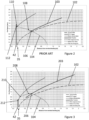
- FIG. 2 The conventional approach to emergency stops is illustrated in Figure 2 , which shows a normal trajectory ("drive profile") 102 of the elevator car 22 approaching the terminal landing 35, and an improper trajectory (“start at wrong pos”) 104 of the elevator car 22 approaching the terminal landing 35 too quickly, such that a conventional emergency stop is triggered.
- the normal trajectory 102 shows the elevator 22 gradually slowing to a halt at the position of the terminal landing 35.
- the improper trajectory 104 shows the elevator car 22 accelerating towards the terminal landing 35, such that at a point 106 approximately 0.45 m above the terminal landing 35, the elevator car 22 is travelling at approximately 1 ms -1 .
- PES response time a short electronic reaction time
- this causes the emergency terminal stopping device 37 to trigger an emergency stop of the elevator car 22 by opening the safety chain 43 and interrupting the supply of power to the whole drive system 30 (i.e. cutting power to the drive device 32 and the brake device 36).
- the drive device 32 immediately stops driving the drive sheave, and the brake device 36 is triggered to engage. However, due to the inherent brake-drop delay of the brake device 36, for a short period of time immediately after the emergency stop is triggered, little or no braking force is actually generated by the brake device 36. Because the power supply to the drive device 32 has also been interrupted, there is also no driving force applied to the elevator car 22. Thus, the elevator car 22 continues to travel and accelerate to point 110 on a brake deceleration profile, roughly level with the terminal landing 35 (i.e. still slightly above the buffer position 42) and travelling at approximately 1.4 ms -1 . Only after this brake drop delay does the brake device 36 start to generate a substantial level of braking force and the elevator car 22 begins to decelerate, slowing slightly before impacting the buffer 42 at point 112 at a speed of approximately 1.3 ms -1 .
- Figure 3 illustrates a method of controlling the elevator car 22 according to an example of the present disclosure.
- Figure 3 again shows the normal trajectory ("drive profile") 102 of the elevator car 22 approaching the terminal landing 35, and an improper trajectory ("start at wrong pos") 104 of the elevator car 22 approaching the terminal landing 35 too quickly, such that an emergency stop is triggered when the improper trajectory 104 intersects a permissible motion profile ("ETS trigger") 203.
- ETS trigger a permissible motion profile
- the safety controller 40 may use information from the absolute position measurement system 41 to compare the speed of the elevator car 22 to the permissible motion profile 203, as well as or instead of relying on the ETSD 37.
- An emergency stop is triggered by opening the safety chain 43.
- the normal trajectory 102 again comprises a gradual deceleration before stopping at the terminal landing 35.
- the improper trajectory 104 shows the elevator car 22 accelerating towards the terminal landing 35, such that at a point 206 approximately 0.4 m above the terminal landing 35, the elevator car 22 is travelling at approximately 1.1 ms -1 , which is above the permitted threshold speed for that position. Therefore, after a short electronic reaction time ("PES response time") (e.g. a reaction time of the emergency terminal stopping device 37 and/or the safety chain 43) in which the elevator car 22 continues to travel and accelerate to point 208, the emergency terminal stopping device 37 triggers an emergency stop of the elevator car 22 by opening the safety chain 43. This triggers the safety controller 40 to immediately interrupt the supply of power to the brake device 36, triggering the brake device 36. However, the drive device 32 continues to be powered and to drive the elevator car 22 via the drive sheave.
- PES response time e.g. a reaction time of the emergency terminal stopping device 37 and/or the safety chain 43
- the safety controller 40 determines a delay to be applied between triggering the brake device 36 (at point 208) and stopping the drive device 32, for instance by retrieving from memory an expected brake-drop delay for the brake device 36.
- the safety controller 40 then waits for a for a time period corresponding to the delay before stopping the drive device 32 at point 210 (e.g. by interrupting a power supply to an inverter of the drive device 32).
- the safety controller 40 controls the drive device 32 to decelerate the elevator car 22, such that at the end of the delay time period at point 210, the elevator car 22 is located just above the terminal landing 35 and travelling at approximately 0.8 ms -1 .
- the brake device 36 starts to generate a substantial level of braking force and the deceleration of the elevator car 22 increases, slowing the elevator car 22 to approximately 0.5 ms -1 before impacting the buffer 42 at point 212.
- ETSD emergency stop threshold speeds can be increased and/or the threshold positions moved closer to the terminal landing 35, allowing more efficient elevator motion profiles to be used (e.g. with higher operating speeds and/or higher deceleration profiles).
- ETS trigger the example permissible motion profile
Landscapes
- Engineering & Computer Science (AREA)
- Automation & Control Theory (AREA)
- Structural Engineering (AREA)
- Elevator Control (AREA)
- Computer Networks & Wireless Communication (AREA)
Claims (12)
- Verfahren zum Steuern einer Aufzugskabine (22), wobei das Verfahren Folgendes umfasst:Antreiben der Aufzugskabine (22) mit einem Antriebssystem (30), das eine Antriebsvorrichtung (32) und eine Bremsvorrichtung (36) beinhaltet;Erkennen eines Notstoppzustands;Auslösen der Bremsvorrichtung (36) in Reaktion auf das Erkennen eines Notstoppzustands;Bestimmen einer Verzögerung, die zwischen dem Auslösen der Bremsvorrichtung (36) und dem Anhalten der Antriebsvorrichtung (32) anzuwenden ist; undAbwarten einer Zeitperiode, die der Verzögerung entspricht, bevor die Antriebsvorrichtung (32) angehalten wirdgekennzeichnet durch Bestimmen, ob der erkannte Notstoppzustand ein bewegungsgefährdender Notstoppzustand ist, und Abwarten der Zeitperiode, die der Verzögerung entspricht, bevor die Antriebsvorrichtung (32) angehalten wird, nur dann, wenn der Notstoppzustand ein bewegungsgefährdender Notstoppzustand ist.
- Verfahren nach Anspruch 1, wobei die anzuwendende Verzögerung zwischen Auslösen der Bremsvorrichtung (36) und dm Anhalten der Antriebsvorrichtung (32) vorbestimmt ist.
- Verfahren nach Anspruch 2, wobei die vorbestimmte Verzögerung, die zwischen Auslösen der Bremsvorrichtung (36) und Anhalten der Antriebsvorrichtung (32) anzuwenden ist, einer erwarteten Bremsabfallverzögerung der Bremsvorrichtung (36) entspricht.
- Verfahren nach einem der vorhergehenden Ansprüche, umfassend Bestimmen der anzuwendenden Verzögerung durch Messen des Niveaus der Bremskraft, die im Gebrauch von der Bremsvorrichtung (36) angewendet wird.
- Verfahren nach Anspruch 4, wobei Messen eines Niveaus der Bremskraft, die im Gebrauch durch die Bremsvorrichtung (36) aufgebracht wird, Überwachen der Bewegung der Aufzugskabine (22) umfasst, nachdem die Bremsvorrichtung (36) ausgelöst worden ist.
- Verfahren nach einem der vorhergehenden Ansprüche, umfassend Steuern der Antriebsvorrichtung (32) zum Abbremsen der Aufzugskabine (22) nachdem die Bremsvorrichtung (36) ausgelöst worden ist.
- Verfahren nach einem der vorhergehenden Ansprüche, wobei Erkennen eines Notstoppzustands Öffnen einer Sicherheitskette umfasst.
- Aufzugsystem (20), umfassend:eine Aufzugskabine (22); undein Antriebssystem, umfassend eine Antriebsvorrichtung (32) und eine Bremsvorrichtung, wobei das Antriebssystem (32) angeordnet ist, um die Aufzugskabine (22) anzutreiben; undein Sicherheitssystem (47), das konfiguriert ist zum:Erkennen eines Notstoppzustands;Auslösen der Bremsvorrichtung (36) in Reaktion auf das Erkennen eines Notstoppzustands;Bestimmen einer Verzögerung, die zwischen dem Auslösen der Bremsvorrichtung (36) und dem Anhalten der Antriebsvorrichtung (32) anzuwenden ist; undAbwarten einer Zeitperiode, die der Verzögerung entspricht, bevor die Antriebsvorrichtung (32) angehalten wird;dadurch gekennzeichnet, dass das Aufzugssystem konfiguriert ist zum Bestimmen, ob der erkannte Notstoppzustand ein bewegungsgefährdender Notstoppzustand ist, und zum Abwarten der Zeitperiode, die der Verzögerung entspricht, bevor die Antriebsvorrichtung (32) angehalten wird, nur dann, wenn der Notstoppzustand ein bewegungsgefährdender Notstoppzustand ist.
- Aufzugssystem (20) nach Anspruch 8, wobei das Sicherheitssystem (47) eine Sicherheitssteuerung (40) umfasst, die konfiguriert ist zum:Bestimmen der Verzögerung, die zwischen dem Auslösen der Bremsvorrichtung (36) und dem Anhalten der Antriebsvorrichtung (32) anzuwenden ist; undAbwarten der Zeitperiode, die der Verzögerung entspricht, bevor die Antriebsvorrichtung (32) angehalten wird.
- Aufzugssystem (20) nach Anspruch 8 oder 9, wobei das Sicherheitssystem (47) eine Sicherheitskette (43) umfasst, die konfiguriert ist zum Erkennen eines Notstoppzustands.
- Aufzugssystem (20) nach einem der Ansprüche 8-10, umfassend ein absolutes Positionsmesssystem (41), das angeordnet ist, um die Position und/oder Geschwindigkeit der Aufzugskabine (22) zu bestimmen.
- Aufzugssystem (20) nach Anspruch 11, wobei das Sicherheitssystem (47) angeordnet ist, um die anzuwendende Verzögerung durch Überwachen der Bewegung der Aufzugskabine (22) zu bestimmen, nachdem die Bremsvorrichtung (36) ausgelöst worden ist, unter Verwendung des absoluten Positionsmesssystems (41).
Priority Applications (3)
| Application Number | Priority Date | Filing Date | Title |
|---|---|---|---|
| EP20212046.5A EP4008664B1 (de) | 2020-12-04 | 2020-12-04 | Verfahren zur verhinderung von schwerkraftsprüngen bei einem notstopp in aufzugssystemen |
| US17/396,096 US20220177263A1 (en) | 2020-12-04 | 2021-08-06 | Method of preventing gravity jump at emergency stop in elevator systems |
| CN202110953249.4A CN114590670B (zh) | 2020-12-04 | 2021-08-19 | 防止电梯系统中在紧急停止时重力跳动的方法 |
Applications Claiming Priority (1)
| Application Number | Priority Date | Filing Date | Title |
|---|---|---|---|
| EP20212046.5A EP4008664B1 (de) | 2020-12-04 | 2020-12-04 | Verfahren zur verhinderung von schwerkraftsprüngen bei einem notstopp in aufzugssystemen |
Publications (2)
| Publication Number | Publication Date |
|---|---|
| EP4008664A1 EP4008664A1 (de) | 2022-06-08 |
| EP4008664B1 true EP4008664B1 (de) | 2024-10-23 |
Family
ID=73726751
Family Applications (1)
| Application Number | Title | Priority Date | Filing Date |
|---|---|---|---|
| EP20212046.5A Active EP4008664B1 (de) | 2020-12-04 | 2020-12-04 | Verfahren zur verhinderung von schwerkraftsprüngen bei einem notstopp in aufzugssystemen |
Country Status (3)
| Country | Link |
|---|---|
| US (1) | US20220177263A1 (de) |
| EP (1) | EP4008664B1 (de) |
| CN (1) | CN114590670B (de) |
Family Cites Families (14)
| Publication number | Priority date | Publication date | Assignee | Title |
|---|---|---|---|---|
| CN101163634B (zh) * | 2006-08-03 | 2011-02-09 | 三菱电机株式会社 | 电梯装置 |
| FI120828B (fi) * | 2007-02-21 | 2010-03-31 | Kone Corp | Elektroninen liikkeenrajoitin ja menetelmä elektronisen liikkeenrajoittimen ohjaamiseksi |
| WO2009008058A1 (ja) * | 2007-07-10 | 2009-01-15 | Mitsubishi Electric Corporation | エレベータ装置 |
| BRPI0814570B1 (pt) * | 2007-07-17 | 2019-04-09 | Inventio Ag | Instalação de elevador com uma cabine de elevador e com um dispositivo de frenagem e processo para a parada de uma cabine de elevador no regime de operação especial através de um dispositivo de frenagem |
| CN102131725B (zh) * | 2008-09-01 | 2013-10-23 | 三菱电机株式会社 | 电梯装置 |
| FI20105033A7 (fi) * | 2010-01-18 | 2011-07-19 | Kone Corp | Menetelmä hissikorin liikkeen valvomiseksi sekä hissijärjestelmä |
| WO2012105986A1 (en) * | 2011-02-04 | 2012-08-09 | Otis Elevator Company | Stop sequencing for braking device |
| WO2012137346A1 (ja) * | 2011-04-08 | 2012-10-11 | 三菱電機株式会社 | マルチカー式エレベータ及びその制御方法 |
| CN105283404B (zh) * | 2013-06-13 | 2017-09-29 | 因温特奥股份公司 | 用于人员运送设备的制动方法、用于执行制动方法的制动控制装置以及具有制动控制装置的人员运送设备 |
| FI125316B (fi) * | 2013-09-10 | 2015-08-31 | Kone Corp | Menetelmä hätäpysäytyksen suorittamiseksi sekä hissin turvajärjestely |
| CN107250022B (zh) * | 2015-03-30 | 2019-02-05 | 三菱电机株式会社 | 电梯的控制系统 |
| EP3277612B1 (de) * | 2015-04-01 | 2020-09-30 | KONE Corporation | Bremssteuerungsvorrichtung und verfahren zur steuerung einer aufzugbremse |
| EP3457555B1 (de) * | 2017-09-19 | 2022-08-03 | KONE Corporation | Antrieb für ein transportbeförderungsmittel |
| US11040848B2 (en) * | 2018-03-27 | 2021-06-22 | Otis Elevator Company | Elevator machine brake delay control |
-
2020
- 2020-12-04 EP EP20212046.5A patent/EP4008664B1/de active Active
-
2021
- 2021-08-06 US US17/396,096 patent/US20220177263A1/en active Pending
- 2021-08-19 CN CN202110953249.4A patent/CN114590670B/zh active Active
Also Published As
| Publication number | Publication date |
|---|---|
| EP4008664A1 (de) | 2022-06-08 |
| CN114590670A (zh) | 2022-06-07 |
| US20220177263A1 (en) | 2022-06-09 |
| CN114590670B (zh) | 2024-02-13 |
Similar Documents
| Publication | Publication Date | Title |
|---|---|---|
| US7669697B2 (en) | Elevator apparatus | |
| US9771243B2 (en) | Elevator safety arrangement for controlling elevator movement | |
| US9546074B2 (en) | Elevator apparatus including an anomalous acceleration detecting mechanism | |
| US9505587B2 (en) | Elevator with acceleration detection | |
| US9637348B2 (en) | Elevator apparatus | |
| CN105283404B (zh) | 用于人员运送设备的制动方法、用于执行制动方法的制动控制装置以及具有制动控制装置的人员运送设备 | |
| EP2141108B1 (de) | Bremsvorrichtung für aufzug | |
| CN104080722B (zh) | 用于减小升降机轿厢的速度的系统和方法 | |
| US20120073909A1 (en) | Elevator device | |
| US9604819B2 (en) | Elevator monitoring arrangement configured to monitor operation of a safety device of an elevator, a controller and method for performing same | |
| JP2004149231A (ja) | エレベータの非常停止装置 | |
| KR101438074B1 (ko) | 에스컬레이터의 안전 운행 정지 방법 | |
| US10662028B2 (en) | Method for moving an elevator car | |
| WO2020090286A1 (ja) | エレベーターの制御システム | |
| EP4008664B1 (de) | Verfahren zur verhinderung von schwerkraftsprüngen bei einem notstopp in aufzugssystemen | |
| CN102177082A (zh) | 电梯的安全电路装置 | |
| US12559343B2 (en) | Emergency terminal deceleration in elevator systems | |
| RU2842090C2 (ru) | Аварийное конечное замедление в лифтовых системах | |
| HK40069287A (en) | A method for testing machinery brakes in an elevator | |
| KR20220012722A (ko) | 에스컬레이터의 보조 브레이크 제어 장치 | |
| JPH0532306B2 (de) | ||
| JPS59207378A (ja) | エレベ−タの保護装置 | |
| HK1199437B (en) | Elevator monitoring arrangement and method for monitoring an elevator |
Legal Events
| Date | Code | Title | Description |
|---|---|---|---|
| PUAI | Public reference made under article 153(3) epc to a published international application that has entered the european phase |
Free format text: ORIGINAL CODE: 0009012 |
|
| STAA | Information on the status of an ep patent application or granted ep patent |
Free format text: STATUS: THE APPLICATION HAS BEEN PUBLISHED |
|
| AK | Designated contracting states |
Kind code of ref document: A1 Designated state(s): AL AT BE BG CH CY CZ DE DK EE ES FI FR GB GR HR HU IE IS IT LI LT LU LV MC MK MT NL NO PL PT RO RS SE SI SK SM TR |
|
| STAA | Information on the status of an ep patent application or granted ep patent |
Free format text: STATUS: REQUEST FOR EXAMINATION WAS MADE |
|
| 17P | Request for examination filed |
Effective date: 20221201 |
|
| RBV | Designated contracting states (corrected) |
Designated state(s): AL AT BE BG CH CY CZ DE DK EE ES FI FR GB GR HR HU IE IS IT LI LT LU LV MC MK MT NL NO PL PT RO RS SE SI SK SM TR |
|
| GRAP | Despatch of communication of intention to grant a patent |
Free format text: ORIGINAL CODE: EPIDOSNIGR1 |
|
| STAA | Information on the status of an ep patent application or granted ep patent |
Free format text: STATUS: GRANT OF PATENT IS INTENDED |
|
| INTG | Intention to grant announced |
Effective date: 20240522 |
|
| GRAS | Grant fee paid |
Free format text: ORIGINAL CODE: EPIDOSNIGR3 |
|
| GRAA | (expected) grant |
Free format text: ORIGINAL CODE: 0009210 |
|
| STAA | Information on the status of an ep patent application or granted ep patent |
Free format text: STATUS: THE PATENT HAS BEEN GRANTED |
|
| AK | Designated contracting states |
Kind code of ref document: B1 Designated state(s): AL AT BE BG CH CY CZ DE DK EE ES FI FR GB GR HR HU IE IS IT LI LT LU LV MC MK MT NL NO PL PT RO RS SE SI SK SM TR |
|
| REG | Reference to a national code |
Ref country code: GB Ref legal event code: FG4D |
|
| REG | Reference to a national code |
Ref country code: CH Ref legal event code: EP |
|
| REG | Reference to a national code |
Ref country code: DE Ref legal event code: R096 Ref document number: 602020039820 Country of ref document: DE |
|
| REG | Reference to a national code |
Ref country code: IE Ref legal event code: FG4D |
|
| REG | Reference to a national code |
Ref country code: LT Ref legal event code: MG9D |
|
| REG | Reference to a national code |
Ref country code: NL Ref legal event code: MP Effective date: 20241023 |
|
| REG | Reference to a national code |
Ref country code: AT Ref legal event code: MK05 Ref document number: 1734697 Country of ref document: AT Kind code of ref document: T Effective date: 20241023 |
|
| PG25 | Lapsed in a contracting state [announced via postgrant information from national office to epo] |
Ref country code: NL Free format text: LAPSE BECAUSE OF FAILURE TO SUBMIT A TRANSLATION OF THE DESCRIPTION OR TO PAY THE FEE WITHIN THE PRESCRIBED TIME-LIMIT Effective date: 20241023 |
|
| PG25 | Lapsed in a contracting state [announced via postgrant information from national office to epo] |
Ref country code: NL Free format text: LAPSE BECAUSE OF FAILURE TO SUBMIT A TRANSLATION OF THE DESCRIPTION OR TO PAY THE FEE WITHIN THE PRESCRIBED TIME-LIMIT Effective date: 20241023 |
|
| PG25 | Lapsed in a contracting state [announced via postgrant information from national office to epo] |
Ref country code: IS Free format text: LAPSE BECAUSE OF FAILURE TO SUBMIT A TRANSLATION OF THE DESCRIPTION OR TO PAY THE FEE WITHIN THE PRESCRIBED TIME-LIMIT Effective date: 20250223 Ref country code: PT Free format text: LAPSE BECAUSE OF FAILURE TO SUBMIT A TRANSLATION OF THE DESCRIPTION OR TO PAY THE FEE WITHIN THE PRESCRIBED TIME-LIMIT Effective date: 20250224 Ref country code: HR Free format text: LAPSE BECAUSE OF FAILURE TO SUBMIT A TRANSLATION OF THE DESCRIPTION OR TO PAY THE FEE WITHIN THE PRESCRIBED TIME-LIMIT Effective date: 20241023 |
|
| PG25 | Lapsed in a contracting state [announced via postgrant information from national office to epo] |
Ref country code: FI Free format text: LAPSE BECAUSE OF FAILURE TO SUBMIT A TRANSLATION OF THE DESCRIPTION OR TO PAY THE FEE WITHIN THE PRESCRIBED TIME-LIMIT Effective date: 20241023 |
|
| PG25 | Lapsed in a contracting state [announced via postgrant information from national office to epo] |
Ref country code: BG Free format text: LAPSE BECAUSE OF FAILURE TO SUBMIT A TRANSLATION OF THE DESCRIPTION OR TO PAY THE FEE WITHIN THE PRESCRIBED TIME-LIMIT Effective date: 20241023 |
|
| PG25 | Lapsed in a contracting state [announced via postgrant information from national office to epo] |
Ref country code: ES Free format text: LAPSE BECAUSE OF FAILURE TO SUBMIT A TRANSLATION OF THE DESCRIPTION OR TO PAY THE FEE WITHIN THE PRESCRIBED TIME-LIMIT Effective date: 20241023 |
|
| PG25 | Lapsed in a contracting state [announced via postgrant information from national office to epo] |
Ref country code: NO Free format text: LAPSE BECAUSE OF FAILURE TO SUBMIT A TRANSLATION OF THE DESCRIPTION OR TO PAY THE FEE WITHIN THE PRESCRIBED TIME-LIMIT Effective date: 20250123 |
|
| PG25 | Lapsed in a contracting state [announced via postgrant information from national office to epo] |
Ref country code: LV Free format text: LAPSE BECAUSE OF FAILURE TO SUBMIT A TRANSLATION OF THE DESCRIPTION OR TO PAY THE FEE WITHIN THE PRESCRIBED TIME-LIMIT Effective date: 20241023 Ref country code: AT Free format text: LAPSE BECAUSE OF FAILURE TO SUBMIT A TRANSLATION OF THE DESCRIPTION OR TO PAY THE FEE WITHIN THE PRESCRIBED TIME-LIMIT Effective date: 20241023 Ref country code: GR Free format text: LAPSE BECAUSE OF FAILURE TO SUBMIT A TRANSLATION OF THE DESCRIPTION OR TO PAY THE FEE WITHIN THE PRESCRIBED TIME-LIMIT Effective date: 20250124 |
|
| PG25 | Lapsed in a contracting state [announced via postgrant information from national office to epo] |
Ref country code: PL Free format text: LAPSE BECAUSE OF FAILURE TO SUBMIT A TRANSLATION OF THE DESCRIPTION OR TO PAY THE FEE WITHIN THE PRESCRIBED TIME-LIMIT Effective date: 20241023 |
|
| PG25 | Lapsed in a contracting state [announced via postgrant information from national office to epo] |
Ref country code: RS Free format text: LAPSE BECAUSE OF FAILURE TO SUBMIT A TRANSLATION OF THE DESCRIPTION OR TO PAY THE FEE WITHIN THE PRESCRIBED TIME-LIMIT Effective date: 20250123 |
|
| PG25 | Lapsed in a contracting state [announced via postgrant information from national office to epo] |
Ref country code: SM Free format text: LAPSE BECAUSE OF FAILURE TO SUBMIT A TRANSLATION OF THE DESCRIPTION OR TO PAY THE FEE WITHIN THE PRESCRIBED TIME-LIMIT Effective date: 20241023 |
|
| PG25 | Lapsed in a contracting state [announced via postgrant information from national office to epo] |
Ref country code: MC Free format text: LAPSE BECAUSE OF FAILURE TO SUBMIT A TRANSLATION OF THE DESCRIPTION OR TO PAY THE FEE WITHIN THE PRESCRIBED TIME-LIMIT Effective date: 20241023 |
|
| PG25 | Lapsed in a contracting state [announced via postgrant information from national office to epo] |
Ref country code: DK Free format text: LAPSE BECAUSE OF FAILURE TO SUBMIT A TRANSLATION OF THE DESCRIPTION OR TO PAY THE FEE WITHIN THE PRESCRIBED TIME-LIMIT Effective date: 20241023 |
|
| PG25 | Lapsed in a contracting state [announced via postgrant information from national office to epo] |
Ref country code: EE Free format text: LAPSE BECAUSE OF FAILURE TO SUBMIT A TRANSLATION OF THE DESCRIPTION OR TO PAY THE FEE WITHIN THE PRESCRIBED TIME-LIMIT Effective date: 20241023 |
|
| PG25 | Lapsed in a contracting state [announced via postgrant information from national office to epo] |
Ref country code: RO Free format text: LAPSE BECAUSE OF FAILURE TO SUBMIT A TRANSLATION OF THE DESCRIPTION OR TO PAY THE FEE WITHIN THE PRESCRIBED TIME-LIMIT Effective date: 20241023 |
|
| REG | Reference to a national code |
Ref country code: DE Ref legal event code: R097 Ref document number: 602020039820 Country of ref document: DE |
|
| PG25 | Lapsed in a contracting state [announced via postgrant information from national office to epo] |
Ref country code: SK Free format text: LAPSE BECAUSE OF FAILURE TO SUBMIT A TRANSLATION OF THE DESCRIPTION OR TO PAY THE FEE WITHIN THE PRESCRIBED TIME-LIMIT Effective date: 20241023 |
|
| PG25 | Lapsed in a contracting state [announced via postgrant information from national office to epo] |
Ref country code: CZ Free format text: LAPSE BECAUSE OF FAILURE TO SUBMIT A TRANSLATION OF THE DESCRIPTION OR TO PAY THE FEE WITHIN THE PRESCRIBED TIME-LIMIT Effective date: 20241023 |
|
| PG25 | Lapsed in a contracting state [announced via postgrant information from national office to epo] |
Ref country code: IT Free format text: LAPSE BECAUSE OF FAILURE TO SUBMIT A TRANSLATION OF THE DESCRIPTION OR TO PAY THE FEE WITHIN THE PRESCRIBED TIME-LIMIT Effective date: 20241023 |
|
| REG | Reference to a national code |
Ref country code: CH Ref legal event code: PL |
|
| PG25 | Lapsed in a contracting state [announced via postgrant information from national office to epo] |
Ref country code: LU Free format text: LAPSE BECAUSE OF NON-PAYMENT OF DUE FEES Effective date: 20241204 |
|
| PLBE | No opposition filed within time limit |
Free format text: ORIGINAL CODE: 0009261 |
|
| STAA | Information on the status of an ep patent application or granted ep patent |
Free format text: STATUS: NO OPPOSITION FILED WITHIN TIME LIMIT |
|
| PG25 | Lapsed in a contracting state [announced via postgrant information from national office to epo] |
Ref country code: SE Free format text: LAPSE BECAUSE OF FAILURE TO SUBMIT A TRANSLATION OF THE DESCRIPTION OR TO PAY THE FEE WITHIN THE PRESCRIBED TIME-LIMIT Effective date: 20241023 |
|
| 26N | No opposition filed |
Effective date: 20250724 |
|
| REG | Reference to a national code |
Ref country code: BE Ref legal event code: MM Effective date: 20241231 |
|
| PG25 | Lapsed in a contracting state [announced via postgrant information from national office to epo] |
Ref country code: BE Free format text: LAPSE BECAUSE OF NON-PAYMENT OF DUE FEES Effective date: 20241231 |
|
| PG25 | Lapsed in a contracting state [announced via postgrant information from national office to epo] |
Ref country code: CH Free format text: LAPSE BECAUSE OF NON-PAYMENT OF DUE FEES Effective date: 20241231 |
|
| PG25 | Lapsed in a contracting state [announced via postgrant information from national office to epo] |
Ref country code: IE Free format text: LAPSE BECAUSE OF NON-PAYMENT OF DUE FEES Effective date: 20241204 |
|
| PGFP | Annual fee paid to national office [announced via postgrant information from national office to epo] |
Ref country code: DE Payment date: 20251126 Year of fee payment: 6 |
|
| PGFP | Annual fee paid to national office [announced via postgrant information from national office to epo] |
Ref country code: GB Payment date: 20251120 Year of fee payment: 6 |
|
| PGFP | Annual fee paid to national office [announced via postgrant information from national office to epo] |
Ref country code: FR Payment date: 20251120 Year of fee payment: 6 |
|
| PG25 | Lapsed in a contracting state [announced via postgrant information from national office to epo] |
Ref country code: CY Free format text: LAPSE BECAUSE OF FAILURE TO SUBMIT A TRANSLATION OF THE DESCRIPTION OR TO PAY THE FEE WITHIN THE PRESCRIBED TIME-LIMIT; INVALID AB INITIO Effective date: 20201204 |