EP4008678A1 - Grue comprenant une colonne de grue et une pompe pour la lubrification de paliers - Google Patents
Grue comprenant une colonne de grue et une pompe pour la lubrification de paliers Download PDFInfo
- Publication number
- EP4008678A1 EP4008678A1 EP20212119.0A EP20212119A EP4008678A1 EP 4008678 A1 EP4008678 A1 EP 4008678A1 EP 20212119 A EP20212119 A EP 20212119A EP 4008678 A1 EP4008678 A1 EP 4008678A1
- Authority
- EP
- European Patent Office
- Prior art keywords
- crane
- pump
- oil
- bearing
- column
- Prior art date
- Legal status (The legal status is an assumption and is not a legal conclusion. Google has not performed a legal analysis and makes no representation as to the accuracy of the status listed.)
- Withdrawn
Links
Images



Classifications
-
- B—PERFORMING OPERATIONS; TRANSPORTING
- B66—HOISTING; LIFTING; HAULING
- B66C—CRANES; LOAD-ENGAGING ELEMENTS OR DEVICES FOR CRANES, CAPSTANS, WINCHES, OR TACKLES
- B66C23/00—Cranes comprising essentially a beam, boom, or triangular structure acting as a cantilever and mounted for translatory of swinging movements in vertical or horizontal planes or a combination of such movements, e.g. jib-cranes, derricks, tower cranes
- B66C23/62—Constructional features or details
- B66C23/84—Slewing gear
-
- B—PERFORMING OPERATIONS; TRANSPORTING
- B66—HOISTING; LIFTING; HAULING
- B66C—CRANES; LOAD-ENGAGING ELEMENTS OR DEVICES FOR CRANES, CAPSTANS, WINCHES, OR TACKLES
- B66C23/00—Cranes comprising essentially a beam, boom, or triangular structure acting as a cantilever and mounted for translatory of swinging movements in vertical or horizontal planes or a combination of such movements, e.g. jib-cranes, derricks, tower cranes
- B66C23/18—Cranes comprising essentially a beam, boom, or triangular structure acting as a cantilever and mounted for translatory of swinging movements in vertical or horizontal planes or a combination of such movements, e.g. jib-cranes, derricks, tower cranes specially adapted for use in particular purposes
- B66C23/36—Cranes comprising essentially a beam, boom, or triangular structure acting as a cantilever and mounted for translatory of swinging movements in vertical or horizontal planes or a combination of such movements, e.g. jib-cranes, derricks, tower cranes specially adapted for use in particular purposes mounted on road or rail vehicles; Manually-movable jib-cranes for use in workshops; Floating cranes
- B66C23/42—Cranes comprising essentially a beam, boom, or triangular structure acting as a cantilever and mounted for translatory of swinging movements in vertical or horizontal planes or a combination of such movements, e.g. jib-cranes, derricks, tower cranes specially adapted for use in particular purposes mounted on road or rail vehicles; Manually-movable jib-cranes for use in workshops; Floating cranes with jibs of adjustable configuration, e.g. foldable
Definitions
- the present disclosure relates to the technical field of slewing mechanisms for cranes, and in particular, lubrication solutions for the slewing bearing or slewing ring.
- the disclosure also relates to a method in relation to the crane.
- a crane mounted on a vehicle often comprises a slewing mechanism provided with an upper and lower bearing arranged to lubricate a slewing motion of a crane column.
- One common approach for lubricating the bearings is to lubricate the lower bearing in an oil bath and to use grease for lubrication of the upper bearing.
- bearing is typically meant radial bearings referring to bearings that support primarily radial loads.
- radial bearings are deep groove ball bearings, and cylindrical roller bearings.
- some cranes e.g. so-called continuous slewing-cranes, are only provided with one bearing, which then is intended to support both radial and axial loads.
- the present invention is thus applicable to bearings intended to support both radial and axial loads.
- JP2017115898A discloses a greasing system for a construction machine such as a jib crane.
- the jib crane has an upper swivel body that is pivotable via a swing device on a lower traveling body.
- the swing device comprises an inner ring attached to the lower traveling body and an outer race attached to the upper swivel body.
- the swing device is rotated by a motor, which further turns the upper body with respect to the lower body.
- a controller outputs a greasing execution command to the lubricating device for lubrication.
- KR19980062266U discloses an automatic grease supply device for driving part of an overhead crane.
- the crane consists of a wire drum that rotates while lifting and lowering of the hoist of the crane.
- a pump is installed at the periphery of the drum, such that when the drum rotates, the pump pushes grease to the bearing through the distribution valve for lubrication.
- US20170022036A1 discloses a crane including a crane pillar supported rotatably about an axis.
- a radial bearing is present for supporting the rotatable crane pillar in a base.
- the radial bearings between the crane base and pillar can further be arranged in an oil bath chamber.
- the oil bath serves as the purpose of lubrication of the bearings.
- the crane further comprises a drive unit, specifically a rack-and-pinion drive unit.
- the crane also comprises a second bearing between the pillar and crane base. The second bearing is located in an oil bath.
- JPH10237897A discloses an automatic lubrication system for a construction machine like hydraulic crane.
- the construction machine comprises a lower traveling body and an upper revolving body.
- the machine further comprises a boom and an arm cylinder, which is operated by a pressure detecting means.
- the pressure detecting means is provided in the hydraulic circuit and detects the work frequency of the actuator or the load amount of the hydraulic oil. The sensor then detects the load, provides a signal to the controller that drives the grease pump to lubricate the bearings.
- CN210318449U discloses a lubricating device for gear column of horizontal rotary large gear ring.
- the large gear ring is arranged below a rotary platform seat frame of a loading and unloading machine like a portal crane.
- the gear ring is installed in a bearing house.
- the lubricating device is driven by the driving gear meshing with the large ring gear, which then lubricates the internal oil passages in the wheel body of the wheel.
- a highpressure oil pump is used for pumping oil from the supply pipe to the discharge pipe.
- the prior art further comprises a motor for rotating the gear.
- a crane bearing that is lubricated with grease needs to be checked and maintained quite frequently by the crane operator or crane owner. Solutions with oil-baths to cover both bearings require quite a large oil bath.
- the object of the present invention is to achieve a crane provided with at least one bearing that is essentially maintenance free in the sense that no manual greasing is required, and that the lubrication with oil of the at least one bearing is accurate, predictable, and easily controlled.
- the crane, and method according to the present invention is based on the idea that a bearing in the slewing house that is not located in an oil-bath should instead be lubricated by distributing oil from the oil-bath using a pump when the rotation of the crane column takes place.
- the drive of the pump consists of gear wheels and roller clutches placed in a combination that will convert a slewing motion into a rotational motion.
- the rotational motion drives the pump that distributes oil to the bearings in the slewing mechanism.
- the crane operator and owner will not need to maintain the lubrication of an upper bearing that is frequently done when lubricated with grease (approximately once a week). Furthermore, by avoiding using grease as in the crane of the present disclosure, the oil will not be contaminated by the grease and there will be less grease stains and contaminations of the working area around the crane. Thus, the crane according to the present invention will hence also have an environmental aspect.
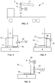
- FIG. 1 is a perspective view of a vehicle 4 provided with a crane 2 according to one embodiment of the present invention.
- the vehicle 4 is e.g. a loader truck, a forestry vehicle, or any vehicle where a crane may be arranged.
- the crane 2 conventionally comprises a crane column 8, and a first boom 14, e.g. a telescopic boom, pivotably connected to the crane column. Further booms may naturally also be arranged, and a tool, e.g. a hook or a grapple to grab logs for a forestry application, may be attached to a tip of the final boom.
- the illustrated crane comprises a slewing house 10 where two bearings are arranged, e.g. in a so-called rack and pinion arrangement.
- a rack and pinion is a type of linear actuator that comprises a circular gear (the pinion) engaging a linear gear (the rack), which operate to translate linear motion to a rotational movement of the crane column 8.
- the linear motion of the rack may be controlled by a hydraulic cylinder.
- FIG 2 is a perspective view of a vehicle 4 provided with a crane 2 according to another embodiment of the present invention.
- This crane is provided with a slewing house 10 provided with one bearing and adapted for continuous slewing.
- the crane comprises a crane column 8 and at least one boom 14, e.g. a telescopic boom, pivotably connected to the crane column.
- further booms may naturally also be arranged, and a tool, e.g. a hook or a grapple to grab logs for a forestry application, may be attached to a final boom extension.
- the crane comprises a crane base 6 arranged to be attached to the vehicle 4, and a crane column 8 rotatably connected to the crane base 6 by a slewing house 10.
- the crane column 8 has an essentially vertical orientation.
- At least a first boom 14 is pivotally connected to the crane column 8, and, as mentioned above, further booms may be attached to the first boom, and a tool may be arranged at a boom tip.
- An actuator 12 comprising e.g. a hydraulic cylinder or a hydraulic motor, is arranged to apply a rotating movement of the crane column 8. The rotating movement may be applied by the actuator driven by a hydraulic system.
- the actuator may provide movement to the crane column via various cogwheels, e.g. arranged at a lower end of the crane column.
- the slewing house 10 comprises at least a first bearing 16 facilitating the rotation of the crane column 8 relative to the crane base 6.
- the crane 2 further comprises an oil-bath chamber 18 containing oil for lubrication of the at least one first bearing 16.
- the oil-bath chamber 18 may either be arranged outside the slewing house 10 as shown in figures 4 and 6 , or inside the slewing house 10 as shown in figures 5 and 7 .
- the crane 2 comprises at least one pump 20 configured to supply, when activated, oil from the oil-bath chamber 18 via an oil feeding tube 36 to the at least one first bearing 16.
- the pump 20 is supplied with oil from the oil-bath chamber 18 via an oil input tube 34.
- the at least one pump 20 is configured to be activated in response to the rotating movement of the crane column 8.
- the arrow from the crane column 8 to the pump illustrates the activation of the at least one pump 20.
- the at least one pump 20 is configured to be directly physically activated by the rotating movement of the crane column 8. This is achieved by providing means that transfers the rotating movement of the crane column 8 to an input movement applicable to operate the pump.
- the nature of the input movement is dependent of the type of pump, and may e.g. be a rotating movement, or a reciprocating movement.
- the at least one pump 20 is configured to be directly physically activated by the rotating movement of the crane column 8 by at least one roller clutch member 22 provided in relation to the crane column 8 to transfer rotating movement from the crane column 8 to the at least one pump 20. This is illustrated in figure 7 .
- the at least one pump 20 is configured to be directly physically activated by the rotating movement of the crane column 8 by at least one cam member provided at the crane column 8 to transfer rotating movement from the crane column 8 to the at least one pump 20.
- the cam member is structured to transform the rotating movement of the crane column to a back and forth motion driving a membrane pump.
- this solution may easily be adapted to presently applied cranes.
- the oil-bath chamber for the lower bearing may be used, adding components for activating the pump and the pump itself.
- the oil may be directed from the pump to the present inlet for grease to the upper bearing, and the oil is then returned to the oil-bath chamber through the slewing house.
- the crane 2 comprises two bearings mounted in the slewing house, the first bearing 16 and a second bearing 32.
- the second bearing 32 is mounted below said first bearing 16, and the oil-bath chamber 18 is structured to enclose the second bearing 32 such that the second bearing 32 is immersed in oil, and wherein the pump 20 is structured to be mounted close to the second bearing 32.
- the pump 20 is mounted close to the second bearing 32 is meant that the pump is mounted such that rotation movement of the crane column may be transferred to the pump by e.g. a roller clutch or a cam.
- Figure 7 discloses a part of the crane provided with a roller clutch member 22 including cogwheels driving the pump distributing oil from the oil-bath chamber 18, where a second bearing is arranged, to the first bearing 16 in the upper part of the slewing house.
- a roller clutch with a gear is placed on a shaft that is in contact with the component 24 (a cogwheel) creating the slewing motion, a second shaft (not shown) with a roller clutch working in the opposite direction is also in contact with the component creating the slewing motion. Both shafts are in contact by gears where one of the gears is equipped with a roller clutch and one of the shafts is driving the oil pump 20.
- Several types of pumps such as Helm pumps, Gear wheel pumps, etc. may be applied.
- the crane comprises at least one pressure sensor arranged to sense pressure of hydraulic fluid in a hydraulic system of the actuator 12 arranged to apply a rotating movement of the crane column 8.
- the crane also comprises a pump control unit 28 (see figure 6 ) configured to determine at least one pump control parameter in dependence of the sensed hydraulic pressure, and to activate the at least one pump 20 by the determined at least one control parameter.
- the crane comprises a pump control unit 28 connected to the crane control unit.
- the crane control unit generates operation commands to the actuators of the crane in response to driving instructions input from e.g. an operator controlling the crane with a remote control unit.
- the pump control unit 28 may hence be activated in response to an operation command activating actuators controlling the slewing of the crane column.
- the pump control unit 28 may be further configured to determine at least one pump control parameter in dependence of the at least one operation command or driving instructions, and to activate the at least one pump 20 by the determined at least one control parameter.
- the at least one pump control parameter comprises one or many of a time period that the pump 20 is activated, an amount of oil that is supplied during the activation, and a variability factor of supplied oil during one activation.
- the variability factor may be set such that the amount of supplied oil is dependent on the expected rotational speed of the crane column. For example, a low speed may result in a low amount of supplied oil, and a high speed may result in a high amount of supplied oil, and that the amount of supplied oil is gradually increased between the low speed, up to the high speed.
- the crane comprises a rotating movement measurement member 30 (see figure 6 ) configured to determine at least one movement parameter related to the rotating movement of the crane column 8.
- the measurement member 30 may e.g. be any optical, inductive or mechanical sensor capable of sensing the movement parameter (e.g. rotational speed).
- the crane comprises a pump control unit 28 configured to determine at least one pump control parameter in dependence of the at least one movement parameter, and to activate the at least one pump 20 by the determined at least one control parameter.
- the at least one pump control parameter comprises one or many of a time period that the pump 20 is activated, an amount of oil that is supplied during the activation, and a variability factor of supplied oil during one activation.
- the variability factor may be set such that the amount of supplied oil is dependent on the rotational speed of the crane column. For example, a low speed may result in a low amount of supplied oil, and a high speed may result in a high amount of supplied oil, and that the amount of supplied oil is gradually increased between the low speed, up to the high speed.
- the oil-bath chamber 18 is arranged separately from the slewing house 10. This is illustrated in figures 4 and 6 .
- the oil-bath chamber 18 may further be placed in such a way that no bearing is located within the oil-bath chamber, but the location of the oil-bath chamber still enables to collect and reuse oil that has once been used to lubricate the bearing. This way oil may be reused in the system which further mitigates the need of frequent maintenance.
- the oil-bath may e.g. be placed below the bearing to the lubricated.
- the oil-bath may as an alternative be arranged to be in connection with a recycling system that collects and returns oil to the oil-bath chamber.
- Figure 8 shows a schematic illustration of a part of a continuous slewing-crane provided with a roller clutch member 22 including cogwheels driving the pump 20 distributing oil from the oil-bath chamber 18 via an oil input tube 34 and by an oil feeding tube 36 to the bearing 16.
- the at least one pump 20 is configured to be activated in response to the rotating movement of the crane column 8.
- the present invention also relates to a method of a crane 2 arranged to be mounted to a vehicle 4.
- the crane has been described in detail above and it is here referred to that description.
- the crane comprises a crane base 6 arranged to be attached to the vehicle 4, a crane column 8 rotatably connected to the crane base 6 by a slewing house 10, an actuator 12 arranged to apply a rotating movement of the crane column 8, and at least a first boom 14 pivotally connected to the crane column 8.
- the slewing house 10 comprises at least a first bearing 16 facilitating the rotation of the crane column 8 relative to the crane base 6, and the crane 2 further comprises an oil-bath chamber 18 for lubrication of the at least one first bearing 16.
- the method comprises activating the at least one pump in response to the rotating movement of the crane column 8, and supplying, by the at least one pump 20, when activated, oil from the oil-bath chamber 18 to the at least one first bearing 16.
- the method further comprises:
- the method comprises:
- the present invention also relates to a vehicle comprising a crane 2 as described above.
Landscapes
- Engineering & Computer Science (AREA)
- Mechanical Engineering (AREA)
- Jib Cranes (AREA)
Priority Applications (1)
| Application Number | Priority Date | Filing Date | Title |
|---|---|---|---|
| EP20212119.0A EP4008678A1 (fr) | 2020-12-07 | 2020-12-07 | Grue comprenant une colonne de grue et une pompe pour la lubrification de paliers |
Applications Claiming Priority (1)
| Application Number | Priority Date | Filing Date | Title |
|---|---|---|---|
| EP20212119.0A EP4008678A1 (fr) | 2020-12-07 | 2020-12-07 | Grue comprenant une colonne de grue et une pompe pour la lubrification de paliers |
Publications (1)
| Publication Number | Publication Date |
|---|---|
| EP4008678A1 true EP4008678A1 (fr) | 2022-06-08 |
Family
ID=73740233
Family Applications (1)
| Application Number | Title | Priority Date | Filing Date |
|---|---|---|---|
| EP20212119.0A Withdrawn EP4008678A1 (fr) | 2020-12-07 | 2020-12-07 | Grue comprenant une colonne de grue et une pompe pour la lubrification de paliers |
Country Status (1)
| Country | Link |
|---|---|
| EP (1) | EP4008678A1 (fr) |
Citations (6)
| Publication number | Priority date | Publication date | Assignee | Title |
|---|---|---|---|---|
| JPH10237897A (ja) * | 1997-02-27 | 1998-09-08 | Hitachi Constr Mach Co Ltd | 建設機械の自動給脂装置 |
| KR19980062266U (ko) | 1997-03-31 | 1998-11-16 | 김종진 | 천정기중기 구동부 그리스 자동공급장치 |
| JP2002097668A (ja) * | 2000-09-27 | 2002-04-02 | Komatsu Ltd | 建設機械の旋回装置 |
| US20170022036A1 (en) | 2013-07-31 | 2017-01-26 | Palfinger Ag | Crane |
| JP2017115898A (ja) | 2015-12-21 | 2017-06-29 | Ihi運搬機械株式会社 | 旋回装置の給脂システム及び建設機械 |
| CN210318449U (zh) | 2019-07-05 | 2020-04-14 | 青岛港国际股份有限公司 | 水平回转大齿圈齿柱的润滑装置 |
-
2020
- 2020-12-07 EP EP20212119.0A patent/EP4008678A1/fr not_active Withdrawn
Patent Citations (6)
| Publication number | Priority date | Publication date | Assignee | Title |
|---|---|---|---|---|
| JPH10237897A (ja) * | 1997-02-27 | 1998-09-08 | Hitachi Constr Mach Co Ltd | 建設機械の自動給脂装置 |
| KR19980062266U (ko) | 1997-03-31 | 1998-11-16 | 김종진 | 천정기중기 구동부 그리스 자동공급장치 |
| JP2002097668A (ja) * | 2000-09-27 | 2002-04-02 | Komatsu Ltd | 建設機械の旋回装置 |
| US20170022036A1 (en) | 2013-07-31 | 2017-01-26 | Palfinger Ag | Crane |
| JP2017115898A (ja) | 2015-12-21 | 2017-06-29 | Ihi運搬機械株式会社 | 旋回装置の給脂システム及び建設機械 |
| CN210318449U (zh) | 2019-07-05 | 2020-04-14 | 青岛港国际股份有限公司 | 水平回转大齿圈齿柱的润滑装置 |
Similar Documents
| Publication | Publication Date | Title |
|---|---|---|
| EP2589707B1 (fr) | Machine de construction avec dispositif de tourelle | |
| US9656839B2 (en) | Jack and support device | |
| EP4008678A1 (fr) | Grue comprenant une colonne de grue et une pompe pour la lubrification de paliers | |
| US4359206A (en) | Severe duty hydraulic cylinder with continuously effective locking device | |
| JPH10279285A (ja) | 旋回ロック機構 | |
| US3738500A (en) | Rotatable mounting for boom type loaders | |
| US2828867A (en) | Crane for trucks | |
| US4211252A (en) | Hydraulic coupler | |
| CN112499500B (zh) | 一种用于回转平台限位锁止控制机构 | |
| CN212609536U (zh) | 装卸鹤管 | |
| CN219242337U (zh) | 摇摆传动装置 | |
| JP6764647B2 (ja) | 旋回装置の給脂システム及び建設機械 | |
| JP2004245356A (ja) | 遊星歯車減速装置 | |
| KR19980086380A (ko) | 감속기 장치 | |
| JP3311823B2 (ja) | 建設・荷役作業用機械の旋回制動装置 | |
| EP4375541A1 (fr) | Actionneur électromécanique pour équipement de travail et équipement de travail | |
| CN222331414U (zh) | 一种自润滑卷扬机构及其起重机 | |
| CN210770183U (zh) | 回转减速机装置及工程机械 | |
| JP5983331B2 (ja) | デッキクレーン | |
| JP2938786B2 (ja) | 旋回装置 | |
| CN223411423U (zh) | 一种便于维护的塔式起重机一字型布局减速器 | |
| EP3619155B1 (fr) | Ensemble actionneur de bras pour grue | |
| CN118651800B (zh) | 一种浅圆仓用升降车姿态调整装置、浅圆仓用升降车 | |
| US9890516B2 (en) | Revolving device for work vehicle, and method for manufacturing same | |
| CN222434088U (zh) | 一种抬升组件及运输机器人 |
Legal Events
| Date | Code | Title | Description |
|---|---|---|---|
| PUAI | Public reference made under article 153(3) epc to a published international application that has entered the european phase |
Free format text: ORIGINAL CODE: 0009012 |
|
| STAA | Information on the status of an ep patent application or granted ep patent |
Free format text: STATUS: THE APPLICATION HAS BEEN PUBLISHED |
|
| AK | Designated contracting states |
Kind code of ref document: A1 Designated state(s): AL AT BE BG CH CY CZ DE DK EE ES FI FR GB GR HR HU IE IS IT LI LT LU LV MC MK MT NL NO PL PT RO RS SE SI SK SM TR |
|
| STAA | Information on the status of an ep patent application or granted ep patent |
Free format text: STATUS: THE APPLICATION IS DEEMED TO BE WITHDRAWN |
|
| 18D | Application deemed to be withdrawn |
Effective date: 20221209 |