EP4008839A1 - Werkzeugmaschinensystem, insbesondere für arbeiten an einer eisenbahnstrecke - Google Patents
Werkzeugmaschinensystem, insbesondere für arbeiten an einer eisenbahnstrecke Download PDFInfo
- Publication number
- EP4008839A1 EP4008839A1 EP21215334.0A EP21215334A EP4008839A1 EP 4008839 A1 EP4008839 A1 EP 4008839A1 EP 21215334 A EP21215334 A EP 21215334A EP 4008839 A1 EP4008839 A1 EP 4008839A1
- Authority
- EP
- European Patent Office
- Prior art keywords
- chainsaw
- battery
- machine
- support
- disc
- Prior art date
- Legal status (The legal status is an assumption and is not a legal conclusion. Google has not performed a legal analysis and makes no representation as to the accuracy of the status listed.)
- Granted
Links
Images





Classifications
-
- E—FIXED CONSTRUCTIONS
- E01—CONSTRUCTION OF ROADS, RAILWAYS, OR BRIDGES
- E01B—PERMANENT WAY; PERMANENT-WAY TOOLS; MACHINES FOR MAKING RAILWAYS OF ALL KINDS
- E01B31/00—Working rails, sleepers, baseplates, or the like, in or on the line; Machines, tools, or auxiliary devices specially designed therefor
- E01B31/02—Working rail or other metal track components on the spot
- E01B31/04—Sectioning or slitting, e.g. by sawing, shearing, flame-cutting
-
- B—PERFORMING OPERATIONS; TRANSPORTING
- B23—MACHINE TOOLS; METAL-WORKING NOT OTHERWISE PROVIDED FOR
- B23D—PLANING; SLOTTING; SHEARING; BROACHING; SAWING; FILING; SCRAPING; LIKE OPERATIONS FOR WORKING METAL BY REMOVING MATERIAL, NOT OTHERWISE PROVIDED FOR
- B23D45/00—Sawing machines or sawing devices with circular saw blades or with friction saw discs
- B23D45/003—Sawing machines or sawing devices with circular saw blades or with friction saw discs for particular purposes
-
- B—PERFORMING OPERATIONS; TRANSPORTING
- B23—MACHINE TOOLS; METAL-WORKING NOT OTHERWISE PROVIDED FOR
- B23D—PLANING; SLOTTING; SHEARING; BROACHING; SAWING; FILING; SCRAPING; LIKE OPERATIONS FOR WORKING METAL BY REMOVING MATERIAL, NOT OTHERWISE PROVIDED FOR
- B23D45/00—Sawing machines or sawing devices with circular saw blades or with friction saw discs
- B23D45/04—Sawing machines or sawing devices with circular saw blades or with friction saw discs with a circular saw blade or the stock carried by a pivoted lever
- B23D45/042—Sawing machines or sawing devices with circular saw blades or with friction saw discs with a circular saw blade or the stock carried by a pivoted lever with the saw blade carried by a pivoted lever
- B23D45/046—Sawing machines or sawing devices with circular saw blades or with friction saw discs with a circular saw blade or the stock carried by a pivoted lever with the saw blade carried by a pivoted lever the pivoted lever being mounted on a carriage
-
- B—PERFORMING OPERATIONS; TRANSPORTING
- B23—MACHINE TOOLS; METAL-WORKING NOT OTHERWISE PROVIDED FOR
- B23D—PLANING; SLOTTING; SHEARING; BROACHING; SAWING; FILING; SCRAPING; LIKE OPERATIONS FOR WORKING METAL BY REMOVING MATERIAL, NOT OTHERWISE PROVIDED FOR
- B23D59/00—Accessories specially designed for sawing machines or sawing devices
- B23D59/007—Accessories specially designed for sawing machines or sawing devices for mounting a portable sawing device on a frame part
-
- B—PERFORMING OPERATIONS; TRANSPORTING
- B25—HAND TOOLS; PORTABLE POWER-DRIVEN TOOLS; MANIPULATORS
- B25F—COMBINATION OR MULTI-PURPOSE TOOLS NOT OTHERWISE PROVIDED FOR; DETAILS OR COMPONENTS OF PORTABLE POWER-DRIVEN TOOLS NOT PARTICULARLY RELATED TO THE OPERATIONS PERFORMED AND NOT OTHERWISE PROVIDED FOR
- B25F5/00—Details or components of portable power-driven tools not particularly related to the operations performed and not otherwise provided for
- B25F5/006—Vibration damping means
-
- E—FIXED CONSTRUCTIONS
- E01—CONSTRUCTION OF ROADS, RAILWAYS, OR BRIDGES
- E01B—PERMANENT WAY; PERMANENT-WAY TOOLS; MACHINES FOR MAKING RAILWAYS OF ALL KINDS
- E01B27/00—Placing, renewing, working, cleaning, or taking-up the ballast, with or without concurrent work on the track; Devices therefor; Packing sleepers
- E01B27/12—Packing sleepers, with or without concurrent work on the track; Compacting track-carrying ballast
- E01B27/13—Packing sleepers, with or without concurrent work on the track
- E01B27/14—Manual tools or hand-held power tools therefor
Definitions
- the invention relates to a machine tool system, in particular for work on a railway track, comprising at least one machine tool such as a rail track saw, and a device for driving the machine.
- the object of the invention is to overcome this drawback.
- the machine tool system according to the invention is characterized in that the machine tool is equipped with an electric motor supplied with power by an electric battery advantageously placed in a backpack carried by the operator. and which is connected by a power cable to the motor.
- the cable is a multi-wire cable in order to be flexible and to limit the heating of the cable.
- each machine tool comprises a specific machine card which identifies the machine and is suitable for dialogue with the battery and is provided with a program for managing the operation of the machine, in cooperation with the battery. .
- the battery comprises a card for switching the discharge channel and the battery charging channel, a BMS card for controlling the switching card and which is adapted to dialogue with the machine card connected to the battery.
- the battery is housed in a casing provided with an internal device for damping vibrations and shocks.
- the damping device comprises a set of flexible wedges held in place by spacers.
- the machine tool is a chainsaw for objects, such as rails, comprising a cutting disk capable of rotating in both directions of rotation, and pivotally mounted on an axis of a fixing support device on the rail, so as to allow the cutting of an object by being placed on one and the other side of the object, by reversal around the pivot axis without dismantling the device support.
- the chainsaw comprises a socket for receiving the axle of the support device, the bottom of which is provided with an electrical contact intended to be actuated by the axle of the socket when the chainsaw is mounted on the bracket.
- control handle is provided with a pivoting lever for controlling the chainsaw.
- the machine comprises two safety handles, one of which is located above and the other below the machine mounted on the support device, in a vertical plane, so that the handle which is the lower handle in the position of rotation of the disc in one direction, becomes the upper handle when the disc rotates in the opposite direction.
- the chainsaw is in working order when the operator has mounted the chainsaw on its support and actuated the control lever and the upper safety handle.
- the socket for receiving the pivot axis on the support is arranged on the axis passing through the center of the disc and a control handle of the machine, located on the end of the machine, opposite the end of the disk side, to ensure the same operating conditions in each direction of rotation of the disk.
- the system comprises a device for transmitting the rotation of the motor shaft to the device by belt, the strand of which located on the side of the axis of the device of the support, this strand is deflected by a puck.
- the machine is in working order when the operator simultaneously actuates a control lever associated with the control handle and the upper safety handle.
- the figure 1 illustrates, in a general way, the machine tool system according to the invention, with a plurality of machine tools usable within the framework of this system, namely, in the example represented, a chainsaw 1, in particular but not exclusively rails of a railway track, a vibrator 2 which makes it possible, for example, to compact the ballast between the sleepers, a drill 3, for example, for rails intended to drill holes in the rails for fixing fishplates or braids connection, and an impact wrench 4 for screwing or unscrewing the fasteners or fishplate bolts.
- the machines are equipped with an electric motor and are supplied with electric power by a battery 5 integrated in an assembly 6 portable by the user of a machine, advantageously in the form of a backpack.
- Each machine can be connected to the battery by a cord or discharge cable 9.
- the machines being high-powered machines, for example of the order of 3 to 10 KW, the cord 9, so as not to be inconvenient for the user is a flexible multi-wire cable comprising a multitude of electrical conductors of small cross-section which allows the cord to be flexible and to limit heating by the electric current circulating between the battery and the electric motor of the machine connected to the battery.
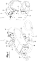
- the machine tool system will be described below, by way of non-limiting example in its embodiment comprising, as machine tool, a chainsaw, in particular but not exclusively, for rails of a path of iron, as represented in 1 to figure 1 and 2 , to figures 3A to 3D and to figures 11 to 13 .
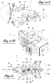
- the chainsaw 1 is provided with an electric motor indicated by the reference 8 on the figures 11B and 15 , and driven by the electric battery 5 disposed in a housing 13 in the form of a shell on which is fixed an over-shell 15.
- the assembly formed by the over-shell 15 and the housing 5 is completed by a carrying device ergonomic 16 to form the assembly 6 of the portable backpack structure by an operator of the machine tool.
- the carrying assembly eliminates the weight of the battery on the machine.
- a battery charger 7 allows rapid recharging of the battery, for example in 2 hours ( figure 1 ).
- the chainsaw 1 is pivotally mounted on a support and fixing vice device 18 with two articulated arms 19, 20.
- One of the two arms, namely the arm 20 is provided at its free end with a vice 21 for fixing by clamping on the rail, while the other arm 19 carries at its free end a shaft 22 on which the chainsaw is pivotally mounted.
- the chainsaw has a socket for receiving the shaft, denoted 25 (page 2).
- an electrical contact (not shown) which is closed when the machine is correctly positioned on the axis 22 of the vice.
- the battery carrying assembly and the latter will be described below in more detail, with reference to the figures 4 to 9 .
- the exploded view of the figure 5 shows the various components of the assembly, namely the battery 5, the casing 13 in the form of a shell, the over-shell 15 and the carrying device 16 comprising essentially two shoulder straps 23, each for one shoulder of the operator, which are mounted on a fixing plate 24 and an adjustable abdominal strap 26, the rear middle part 27 of which is widened to allow the mounting of the strap on the casing 13.
- plates 29, 30 ( Figures 7E, 7F ) which are formed by sheets to be glued inside the hull and which support sealed and threaded inserts 32 for fixing the carrying device 16 to the housing using screws for fixing parts 24, 27 of the device 16 in the threaded inserts 32.
- the plates are wide to provide a good grip surface and a good range to absorb the forces.
- the sealed inserts 32 are crimped on the sheet before bonding to the shell.
- the casing is designed to constitute the external protective element of the battery and the over-shell 15 fixed to the shell provides additional security.
- the shell casing 13 for external protection of the battery consists of two half-shells 34, 35 made of fibreglass/polyester resin characterized by high resistance and an excellent rigidity/mass ratio.
- the reference 37 designates a seal cover interposed between the two half-shells.
- a set of soft wedges 40 and 41 ( Fig. 7C ) is positioned on the inner sides of the hull. These wedges allow the correct positioning of the battery in the hull and have a damping function. They are held in place by spacers 42 until the battery is mounted in the hull.
- the wedge 40 is located at the junction of the two half-shells, while the two wedges 41 are arranged in planes perpendicular to the wedge 40 near the lateral sides of the housing.
- connection plate 45 ( figures 8, 9 ) located at the opening of the case. It is accommodated by flexible shock-proof wedges 40, 41 which form a structure of the foam skeleton type.
- Two tabs 47 are each fixed on a large side face of the battery, at its end on the opening side. They are intended to suppress the movement of the battery towards the connection plate while ensuring shock absorption. To this end, when the battery is placed in the casing, the free ends of the flexible tabs 47 come into engagement at 49 behind a stop element at the entrance to the casing.
- the battery is associated with a BMS (Battery Management System) card 51, a switching card 53 and a connector card 55, which are placed between the heart of the battery and the connection board 45.
- BMS Battery Management System
- the heart of the battery in the The example shown is made up of 130 cells of the Li-Ion type. The cells are held side by side by two holding elements (not shown) each arranged at one end of the block of cells. Two electronic cards are provided to interconnect the cells and to receive the temperature sensors.
- the connector plate 45 ( figure 6 and 8 ) carries on its outer face, a discharge connector 60 to which the discharge cord which constitutes the power cable is connected, to connect the battery to the machine used.
- This connector is waterproof, it is equipped with a removable cap to protect it when the cord is not connected.
- the plate also carries a charging connector 62 for connecting a charger to the battery, three connectors 64 which allow accessories to be connected to the battery, such as the human/machine interface HMI, an LED lamp and the USB charging cord , a start button 66 and a hatch 68 for access to a memory card.
- the charging connector 62 is fitted with a self-closing cover which protects the electrical contact when the charger is not plugged in.
- the start button 66 is a lighted button.
- the plate When it is on, the battery is on. When it is off, the battery is off. The battery goes into "sleep" mode after 10 minutes after being turned off (power saving mode) or after 10 minutes of inactivity. Flashing modes are provided to signal different types of faults to the user.
- the plate also carries a respirator 69. Concerning the respirator 69, as the battery is sealed, it makes it possible to balance the pressure between the interior and the exterior of the battery by avoiding any introduction of humidity.
- the memory card contains the battery operating parameter as well as information about the machines used.
- the 55 connector card carries a 48 V/5 V transformer which supplies the accessories, the power supply to the machine card by system initiation, the connectors for the distribution of the accessory harnesses and the CAN BUS, the connectors for the start-up connection 66, a "low battery” alarm buzzer indicating to the user that the battery must be recharged in order not to damage the cells, the battery power connection pads and a connector for multi-spindle discharge.
- the battery 5 output there are two large section power cables which are not flexible.
- the function of the multi-pin connector is to distribute the high power over a plurality of pins compatible with the plurality of conductors of smaller section of the discharge cord or cable, which is designed to be as flexible as possible to facilitate the use of machines and to limit heating of the cord.
- the latter comprises twenty-four pins, namely ten pins for +48 V, ten pins for 0 V, one + 5 V pin, one 0 V pin , a pin for CAN high and a pin for CAN low.
- the discharge cable has one conductor for each pin.
- the connector card further comprises a relay which protects the load channel, the function of which is to prevent the presence of current on the load channel, when no connector is connected to it.
- a circuit is provided in the charging connector wiring that allows the charging circuit to be closed when connected to the battery.
- the BMS 51 board provides safety functions, namely overload protection, short circuit protection and temperature monitoring. It also provides cell management, namely the monitoring of cell discharge and charge. Then the card performs communication functions, i.e. controlling the switching card, managing the memory card, the buzzer and the human/machine interface HMI and, where applicable, the links with other applications.
- the switching board 53 comprises an electronic relay which is controlled by the BMS board 51 and has the function of providing the power cut-off function on the battery discharge channel, the management of the charging channel, the management the pre-charge circuit of the motor controllers of the machines, and the protection against overloads and short circuits.
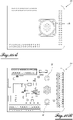
- Each machine which will be connected to the battery 5 is equipped with a machine card 77, the two faces of which are represented in figures 10A and 10B , and which carries a multi-pin connector 79 allowing the connection of the discharge cord, and two power pads 81 which respectively combine the ten pins of + 48 V and the ten pins of 0 V, for the electrical power supply of the motor controller .
- the card also includes the connection terminals for the inputs/outputs and is suitable for managing the logic inputs/outputs.
- the card also has the function of establishing a dialogue with the battery for the identification of the machine during connection and of sending commands to the motor controller 78 for controlling the motor.
- Each machine card has a program which manages the specific operation of the machine according to the following operating logic: the discharge cord is connected to the machine card, the permanent voltage 0/5 V enables the machine card to be started , an encrypted dialogue on the CAN BUS engages between the machine card and the BMS card 51. If the machine card is recognized, the BMS card authorizes the closing of the 48 V discharge channel. The switching card 53 manages the pre -charge of the motor controller 78. The machine is ready for use if the start-up conditions are met.
- the chainsaw 1 as represented in figure 1 , 3A to 3D and 11 to 13 .
- This chainsaw comprises a cutting disc 80 driven in rotation, via a transmission device 82, by an electric motor 8 enclosed in a casing 84.
- the chainsaw is provided at its end opposite that of the disc with a control handle 86 provided with a pivoting lever 87 for controlling the motor so that the latter rotates the disc in one or the other direction of rotation by pivoting the lever upwards or downwards.
- the chainsaw further comprises a pair of safety handles, namely an upper handle 88 and a lower handle 89.
- each handle is located either above or below the casing, at a certain distance from the upper or lower surface thereof, and is carried by a rod 91 which extends in a plane parallel to plane of the disk, projecting above and below the casing and terminating in an end in the form of a foot 92.
- Each handle 88, 89 extends perpendicular to its support rod and to the plane of the disk, near the base of the stem. Each handle is associated with a guard 93.
- the multipin connector 79 for connecting the discharge cord can be seen.
- Attached to a lateral side of the crankcase is a cowl 96 which covers an air filter 97 through which, by an internal electric fan, a flow of engine cooling air is drawn in, which passes through the engine and is discharged to the front disc side.
- the suction opening is on the operator side.
- the air filter prevents metal particles produced by rail cutting or abrasive particles from disc wear from entering the engine.
- the socket 25 for receiving the support pin of the vice.
- an LED display is provided on the housing, which gives the operator information on the quantity of energy remaining available in the battery, compared to the amount of energy needed to make a complete cut, following an analysis made by the machine card which lights up the LEDs according to the result.
- a green LED for example, means that the cut can be started and there is enough energy to finish it.
- the lighting of a yellow LED indicates that a final complete cut is still possible.
- the operator should not start a cut because there is not enough energy in the battery to finish it.
- the display also includes a "filter clogging" LED which indicates to the operator that he has reached a number of cuts which requires the replacement of the air filter.
- a very advantageous particularity of the chainsaw according to the invention lies in the fact that it makes it possible to cut a rail by reversal, without the operator having to dismantle the machine from the axis of the vice. , as illustrated by the figures 3A to 3D .
- the Figure 3A shows the chainsaw, mounted on the axis of the support vice, with two articulated arms 19, 20.
- the operator started the cut by activating the safety handle 88 and the lever 87 for controlling the rotation when he grasps the handle 86. If the cut is not possible in one go, the operator takes the disc out of the start of the cut, stops the rotation of the disc by releasing the control lever and performs the reversal of the machine without dismantling the vice axis 22, by passing it from the position of the Figure 3B , on one side of the rail, in the position according to the Fig. 3C on the other side of the rail. To continue the cut, the operator activates the other safety handle 89 which is now the upper handle and the control lever 87 which he rotates in the opposite direction with respect to the first phase so that the disc can rotate. now in the opposite direction.
- the receiving sleeve of the vice screw is placed in the axis which passes through the center of the disc 80 and the control handle 86, 87 and is indicated by the references X, X', so as to have a symmetry at the level of the kinematics of the set of levers constituted by the vice arms to ensure the same operating conditions in both directions of rotation of the disk.
- the figure 12 shows the particular configuration of the components of the device for transmitting rotary motion from the motor shaft to the disc shaft.
- This transmission is carried out using an endless transmission belt 101, which transmits the rotational movement of a roller 103 integral in rotation with the shaft of the motor to a roller 105 integral in rotation with the disc.
- a roller 103 integral in rotation with the shaft of the motor
- a roller 105 integral in rotation with the disc.
- this strand is deflected by a roller 108.
- the belt 101 is advantageously an elastic belt, ribbed in the direction of the length, which does not require tension adjustment or maintenance.
- the invention provides for the use of a roller 109, which is supported by a lever 111 mounted pivoting around a pin 113 and capable of being fixed in position by a screw 115.
- the figure 14 illustrates the different ways of cutting a rail.
- the image on the left shows the type of cut consisting of cutting the entire rail without having to turn the machine over. To perform this type of cut, the machine must be equipped with a new blade.
- the other two images illustrate a two-stage cut when the disc wear has reached a certain degree and its diameter has decreased so that a full cut is no longer possible. In this case, in accordance with the image in the middle, the operator, working on a first side, first cuts the entire head and the rail core, as well as part of the shoe, the hatched part remaining uncut.
- the operator After idling the engine and waiting for the disc to come to a complete stop, the operator removes the disc from the start of the cut and rotates the machine to the other side of the rail 180°, restarts the chainsaw and completes the rail cut, as shown in the image to the right.
- the system according to the invention can be used with other machine tools such as a vibrator shown at the top of the figure 1 and denoted 2, a Rail Drill 3 shown in the middle and the Impact Wrench 4 shown at the bottom.
- a vibrator shown at the top of the figure 1 and denoted 2
- a Rail Drill 3 shown in the middle
- the Impact Wrench 4 shown at the bottom.
- the battery discharge cable is connected to the connector indicated by the reference 121.
- the starting of the vibrator and its stopping is done by actuating or releasing the handle 123.
- the electric motor is cooled by a air flow generated by an electric fan and passing through the motor.
- an air filter 125 is provided, the removable cover of which has been removed in the figure.
- the motor, filtration and electrical box assembly is covered by a plastic cover, not shown.
- An LED display 127 is present to indicate approximate remaining work time.
- the battery discharge cable is connected to the connector indicated at 131.
- each machine tool is equipped with a specific machine card 77 which is specific to it.
- the machine card of the connected machine establishes a dialogue with the BMS card, via the CAN BUS to allow the identification of the machine using an identification code that the machine card sends to the BMS card.
- the BMS card which has the function of controlling the switching card, authorizes the closing of the discharge path passing from the battery, through the switching card, the connector card, the multi-wire cable, the machine board and the motor controller to the motor.
- the specific operation of each machine is managed by the machine card which has the operating program and therefore sends commands to the motor controller for its control.
- the machine is then ready to be used if the start-up conditions are met, i.e. if the operator has activated the control devices, in the case of the chainsaw the control handle and the corresponding to the desired direction of rotation of the cutting disc.
Landscapes
- Engineering & Computer Science (AREA)
- Mechanical Engineering (AREA)
- Architecture (AREA)
- Civil Engineering (AREA)
- Structural Engineering (AREA)
- Sawing (AREA)
- Machines For Laying And Maintaining Railways (AREA)
- Drilling And Boring (AREA)
- Portable Power Tools In General (AREA)
- Finish Polishing, Edge Sharpening, And Grinding By Specific Grinding Devices (AREA)
Applications Claiming Priority (3)
| Application Number | Priority Date | Filing Date | Title |
|---|---|---|---|
| FR1855597A FR3082855B1 (fr) | 2018-06-22 | 2018-06-22 | Systeme de machine-outil, notamment pour des travaux sur une voie de chemin ferre |
| EP19742452.6A EP3810857A1 (de) | 2018-06-22 | 2019-06-21 | Werkzeugmaschinensystem, insbesondere für arbeiten an einer eisenbahnstrecke |
| PCT/FR2019/051530 WO2019243756A1 (fr) | 2018-06-22 | 2019-06-21 | Système de machine-outil, notamment pour des travaux sur une voie de chemin ferré |
Related Parent Applications (1)
| Application Number | Title | Priority Date | Filing Date |
|---|---|---|---|
| EP19742452.6A Division EP3810857A1 (de) | 2018-06-22 | 2019-06-21 | Werkzeugmaschinensystem, insbesondere für arbeiten an einer eisenbahnstrecke |
Publications (2)
| Publication Number | Publication Date |
|---|---|
| EP4008839A1 true EP4008839A1 (de) | 2022-06-08 |
| EP4008839B1 EP4008839B1 (de) | 2024-05-01 |
Family
ID=63407451
Family Applications (2)
| Application Number | Title | Priority Date | Filing Date |
|---|---|---|---|
| EP21215334.0A Active EP4008839B1 (de) | 2018-06-22 | 2019-06-21 | Schneidesystem, insbesondere für arbeiten an schienen einer eisenbahnstrecke |
| EP19742452.6A Pending EP3810857A1 (de) | 2018-06-22 | 2019-06-21 | Werkzeugmaschinensystem, insbesondere für arbeiten an einer eisenbahnstrecke |
Family Applications After (1)
| Application Number | Title | Priority Date | Filing Date |
|---|---|---|---|
| EP19742452.6A Pending EP3810857A1 (de) | 2018-06-22 | 2019-06-21 | Werkzeugmaschinensystem, insbesondere für arbeiten an einer eisenbahnstrecke |
Country Status (7)
| Country | Link |
|---|---|
| US (1) | US20210246615A1 (de) |
| EP (2) | EP4008839B1 (de) |
| JP (1) | JP7408649B2 (de) |
| CA (1) | CA3104389A1 (de) |
| DE (1) | DE202019005809U1 (de) |
| FR (1) | FR3082855B1 (de) |
| WO (1) | WO2019243756A1 (de) |
Families Citing this family (10)
| Publication number | Priority date | Publication date | Assignee | Title |
|---|---|---|---|---|
| FR3082855B1 (fr) | 2018-06-22 | 2021-03-12 | Soc Des Anciens Etablissements L Geismar | Systeme de machine-outil, notamment pour des travaux sur une voie de chemin ferre |
| EA202092780A1 (ru) * | 2018-07-25 | 2021-03-01 | Робель Банбаумашинен Гмбх | Виброуплотнитель балластной подушки железнодорожного пути |
| DE102019200303A1 (de) | 2019-01-11 | 2020-07-16 | Robel Bahnbaumaschinen Gmbh | Trennschleifgerät und Verfahren zum Durchtrennen einer Schiene eines Gleises |
| WO2022028681A1 (de) | 2020-08-04 | 2022-02-10 | Robel Bahnbaumaschinen Gmbh | Gleisbearbeitungsmaschine und verfahren zur gleisbearbeitung |
| JP2024545625A (ja) | 2021-12-01 | 2024-12-10 | ヒルティ アクチエンゲゼルシャフト | 機械工具と電力供給装置とを有するシステム、インターフェース及び電力供給装置 |
| EP4191723A1 (de) * | 2021-12-01 | 2023-06-07 | Hilti Aktiengesellschaft | Energieversorgungsvorrichtung und werkzeugmaschine mit einer solchen energieversorgungsvorrichtung |
| EP4190499A1 (de) | 2021-12-01 | 2023-06-07 | Hilti Aktiengesellschaft | System, schnittstelle, werkzeugmaschine und energieversorgungsvorrichtung |
| EP4190498A1 (de) | 2021-12-01 | 2023-06-07 | Hilti Aktiengesellschaft | Systeme, die werkzeugmaschinen und eine energieversorgungsvorrichtungen umfassen, sowie energieversorgungsvorrichtung |
| CN114227476B (zh) * | 2021-12-24 | 2023-02-03 | 永康市开源动力工具有限公司 | 角磨机用防外压板越锁越紧的垫片结构 |
| CN117773626B (zh) * | 2024-02-28 | 2024-05-03 | 山西众合无磁钻具股份有限公司 | 一种钻铤加工的机床夹具 |
Citations (6)
| Publication number | Priority date | Publication date | Assignee | Title |
|---|---|---|---|---|
| US4068415A (en) | 1976-01-12 | 1978-01-17 | Racine Railroad Products, Inc. | Rail cutting apparatus |
| FR2508071A1 (fr) * | 1981-06-23 | 1982-12-24 | Caballero Patrick | Machine pour l'execution d'operations variees : percage, tronconnage, tirefonnage, boulonnage... sur une voie ferree |
| US5486136A (en) * | 1992-06-15 | 1996-01-23 | Kabushiki Kaisha Yamazaki Haguruma Seisakusho | Cutting machine for railroad rail |
| WO2008087285A2 (fr) * | 2006-12-27 | 2008-07-24 | Societe Des Anciens Etablissements Lucien Geismar | Tronçonneuse de rail ou analogue |
| WO2013187837A2 (en) * | 2012-06-12 | 2013-12-19 | Husqvarna Ab | Electric cutting system |
| WO2018097194A1 (ja) | 2016-11-24 | 2018-05-31 | 株式会社マキタ | 電動作業機 |
Family Cites Families (16)
| Publication number | Priority date | Publication date | Assignee | Title |
|---|---|---|---|---|
| FR2267418B1 (de) * | 1974-04-09 | 1976-10-08 | Mecanique Ste Turripinoise | |
| US5016510A (en) * | 1989-08-18 | 1991-05-21 | Gardner Frederick P | Power saw arrangement |
| JPH0762321B2 (ja) * | 1992-06-15 | 1995-07-05 | 株式会社山崎歯車製作所 | 鉄道レール穿孔機 |
| FR2771318B1 (fr) * | 1997-11-27 | 2000-01-21 | Turripinoise De Mecanique Stum | Tronconneuse de rail |
| FR2862558B1 (fr) * | 2003-11-20 | 2006-04-28 | Pellenc Sa | Outil portatif electrique autonome de puissance |
| FR2920683B1 (fr) * | 2007-09-06 | 2010-02-12 | Pellenc Sa | Appareils electroportatifs polyvalents. |
| KR101147231B1 (ko) | 2010-07-23 | 2012-05-18 | 삼성에스디아이 주식회사 | 전지 팩 및 그의 충방전 제어 방법 |
| EP2635411B1 (de) | 2010-11-04 | 2017-03-22 | Ingersoll-Rand Company | Schnurlose elektrowerkzeuge mit einer universellen steuerung sowie werkzeug- und batterie-identifikation |
| FR2973815B1 (fr) * | 2011-04-07 | 2014-08-29 | Pellenc Sa | Souffleur electroportatif autonome a vitesse de sortie d'air modulable |
| EP2869965B1 (de) * | 2012-07-04 | 2016-08-17 | Black & Decker Inc. | Elektrowerkzeug |
| US9391305B2 (en) | 2012-07-06 | 2016-07-12 | Hitachi Koki Co., Ltd. | Backpack-type power supply including operation portion |
| US11162228B2 (en) * | 2013-05-07 | 2021-11-02 | Husqvarna Ab | Apparatus and system for securing a cutting device |
| EP2965886B1 (de) * | 2014-06-18 | 2020-12-02 | Husqvarna AB | Fliesen- oder steinsägenanordnung mit verbesserter klingenbenetzungsfähigkeit |
| KR102028114B1 (ko) * | 2016-09-13 | 2019-10-02 | 주식회사 엘지화학 | 배터리 팩 |
| US10158301B2 (en) * | 2017-02-14 | 2018-12-18 | Black & Decker Inc. | Sensorless thermal protection for power tools |
| FR3082855B1 (fr) | 2018-06-22 | 2021-03-12 | Soc Des Anciens Etablissements L Geismar | Systeme de machine-outil, notamment pour des travaux sur une voie de chemin ferre |
-
2018
- 2018-06-22 FR FR1855597A patent/FR3082855B1/fr active Active
-
2019
- 2019-06-21 CA CA3104389A patent/CA3104389A1/fr active Pending
- 2019-06-21 US US17/255,102 patent/US20210246615A1/en not_active Abandoned
- 2019-06-21 DE DE202019005809.5U patent/DE202019005809U1/de active Active
- 2019-06-21 EP EP21215334.0A patent/EP4008839B1/de active Active
- 2019-06-21 EP EP19742452.6A patent/EP3810857A1/de active Pending
- 2019-06-21 JP JP2021520471A patent/JP7408649B2/ja active Active
- 2019-06-21 WO PCT/FR2019/051530 patent/WO2019243756A1/fr not_active Ceased
Patent Citations (6)
| Publication number | Priority date | Publication date | Assignee | Title |
|---|---|---|---|---|
| US4068415A (en) | 1976-01-12 | 1978-01-17 | Racine Railroad Products, Inc. | Rail cutting apparatus |
| FR2508071A1 (fr) * | 1981-06-23 | 1982-12-24 | Caballero Patrick | Machine pour l'execution d'operations variees : percage, tronconnage, tirefonnage, boulonnage... sur une voie ferree |
| US5486136A (en) * | 1992-06-15 | 1996-01-23 | Kabushiki Kaisha Yamazaki Haguruma Seisakusho | Cutting machine for railroad rail |
| WO2008087285A2 (fr) * | 2006-12-27 | 2008-07-24 | Societe Des Anciens Etablissements Lucien Geismar | Tronçonneuse de rail ou analogue |
| WO2013187837A2 (en) * | 2012-06-12 | 2013-12-19 | Husqvarna Ab | Electric cutting system |
| WO2018097194A1 (ja) | 2016-11-24 | 2018-05-31 | 株式会社マキタ | 電動作業機 |
Also Published As
| Publication number | Publication date |
|---|---|
| CA3104389A1 (fr) | 2019-12-26 |
| EP4008839B1 (de) | 2024-05-01 |
| EP3810857A1 (de) | 2021-04-28 |
| JP2021529679A (ja) | 2021-11-04 |
| FR3082855A1 (fr) | 2019-12-27 |
| FR3082855B1 (fr) | 2021-03-12 |
| WO2019243756A1 (fr) | 2019-12-26 |
| JP7408649B2 (ja) | 2024-01-05 |
| DE202019005809U1 (de) | 2022-04-20 |
| US20210246615A1 (en) | 2021-08-12 |
Similar Documents
| Publication | Publication Date | Title |
|---|---|---|
| EP4008839B1 (de) | Schneidesystem, insbesondere für arbeiten an schienen einer eisenbahnstrecke | |
| EP2159018B1 (de) | Sicherheitsvorrichtung für ortsveränderliche Werkzeuge mit Wärmekraftmaschinen, die eine Abschalten ihrer Funktion bei Auftreten von unvorhergesehenen heftigen und gewaltsamen Bewegungen ermöglicht | |
| JP7027490B2 (ja) | 電動工具 | |
| FR2828787A1 (fr) | Tondeuse a gazon electrique | |
| JP2007006903A (ja) | リール型の草刈り機アセンブリ | |
| FR2730376A1 (fr) | Tete motrice pour dispositif de coupe de l'herbe electrique | |
| FR2586608A1 (fr) | Tronconneuse a chaine a moteur serie electrique et frein de surete | |
| US7406902B2 (en) | Battery powered table saws | |
| FR2916320A1 (fr) | Outil tournant tel qu'un outil de vissage comprenant un organe de commande, des moyens de reglage de la vitesse de rotation separables de l'outil, et organe de commande correspondant | |
| FR3095820A1 (fr) | Système de tronçonneuse, notamment pour des travaux sur une voie ferrée | |
| CN102554971B (zh) | 链锯 | |
| CN209288432U (zh) | 切割机 | |
| FR2834233A3 (fr) | Outil a moteur comportant un systeme d'alimentation perfectionne | |
| FR2636498A1 (fr) | Dispositif tondeuse a gazon alimente par une batterie | |
| EP3808589B1 (de) | Elektrisches motorisierungssystem für baumaschine oder technische wartungsmaschine, insbesondere für schienenverkehr | |
| WO2010086777A1 (fr) | Dispositif de soufflage de feuilles et autres débris végétaux | |
| EP0253032A1 (de) | Konstruktionsmaterialienschneidemaschine | |
| JP2010124697A (ja) | 充電式芝刈り機 | |
| FR2776858A1 (fr) | Dispositif de maintien, de positionnement, ou de serrage, a actionnement electrique | |
| FR2584566A1 (fr) | Secateur automatique pour la taille de la vigne, arbres et autres... | |
| CN213817297U (zh) | 一种充电可自动调节开断的移动电源 | |
| FR3012357A1 (fr) | Dispositif de mise en obturation amovible et adaptable pour une targette d'obturation d'aspiration d'une machine de travail industriel et machine equipee d'un tel dispositif | |
| JP7604143B2 (ja) | 手持式作業機 | |
| CN214245059U (zh) | 一种定位效果好的涤纶布加工用裁布机 | |
| FR2824196A1 (fr) | Dispositif de stockage d'un cable electique formant une rallonge |
Legal Events
| Date | Code | Title | Description |
|---|---|---|---|
| PUAI | Public reference made under article 153(3) epc to a published international application that has entered the european phase |
Free format text: ORIGINAL CODE: 0009012 |
|
| STAA | Information on the status of an ep patent application or granted ep patent |
Free format text: STATUS: THE APPLICATION HAS BEEN PUBLISHED |
|
| AC | Divisional application: reference to earlier application |
Ref document number: 3810857 Country of ref document: EP Kind code of ref document: P |
|
| AK | Designated contracting states |
Kind code of ref document: A1 Designated state(s): AL AT BE BG CH CY CZ DE DK EE ES FI FR GB GR HR HU IE IS IT LI LT LU LV MC MK MT NL NO PL PT RO RS SE SI SK SM TR |
|
| STAA | Information on the status of an ep patent application or granted ep patent |
Free format text: STATUS: REQUEST FOR EXAMINATION WAS MADE |
|
| 17P | Request for examination filed |
Effective date: 20220607 |
|
| RBV | Designated contracting states (corrected) |
Designated state(s): AL AT BE BG CH CY CZ DE DK EE ES FI FR GB GR HR HU IE IS IT LI LT LU LV MC MK MT NL NO PL PT RO RS SE SI SK SM TR |
|
| STAA | Information on the status of an ep patent application or granted ep patent |
Free format text: STATUS: EXAMINATION IS IN PROGRESS |
|
| 17Q | First examination report despatched |
Effective date: 20220926 |
|
| TPAC | Observations filed by third parties |
Free format text: ORIGINAL CODE: EPIDOSNTIPA |
|
| GRAP | Despatch of communication of intention to grant a patent |
Free format text: ORIGINAL CODE: EPIDOSNIGR1 |
|
| STAA | Information on the status of an ep patent application or granted ep patent |
Free format text: STATUS: GRANT OF PATENT IS INTENDED |
|
| RIC1 | Information provided on ipc code assigned before grant |
Ipc: B23D 45/00 20060101ALN20231019BHEP Ipc: E01B 31/06 20060101ALN20231019BHEP Ipc: B23D 59/00 20060101ALI20231019BHEP Ipc: B23D 45/16 20060101ALI20231019BHEP Ipc: E01B 27/14 20060101ALI20231019BHEP Ipc: E01B 31/04 20060101AFI20231019BHEP |
|
| INTG | Intention to grant announced |
Effective date: 20231129 |
|
| RIC1 | Information provided on ipc code assigned before grant |
Ipc: B23D 45/00 20060101ALN20231117BHEP Ipc: E01B 31/06 20060101ALN20231117BHEP Ipc: B23D 59/00 20060101ALI20231117BHEP Ipc: B23D 45/16 20060101ALI20231117BHEP Ipc: E01B 27/14 20060101ALI20231117BHEP Ipc: E01B 31/04 20060101AFI20231117BHEP |
|
| GRAS | Grant fee paid |
Free format text: ORIGINAL CODE: EPIDOSNIGR3 |
|
| GRAA | (expected) grant |
Free format text: ORIGINAL CODE: 0009210 |
|
| STAA | Information on the status of an ep patent application or granted ep patent |
Free format text: STATUS: THE PATENT HAS BEEN GRANTED |
|
| RAP3 | Party data changed (applicant data changed or rights of an application transferred) |
Owner name: GEISMAR |
|
| AC | Divisional application: reference to earlier application |
Ref document number: 3810857 Country of ref document: EP Kind code of ref document: P |
|
| AK | Designated contracting states |
Kind code of ref document: B1 Designated state(s): AL AT BE BG CH CY CZ DE DK EE ES FI FR GB GR HR HU IE IS IT LI LT LU LV MC MK MT NL NO PL PT RO RS SE SI SK SM TR |
|
| REG | Reference to a national code |
Ref country code: GB Ref legal event code: FG4D Free format text: NOT ENGLISH |
|
| REG | Reference to a national code |
Ref country code: CH Ref legal event code: EP |
|
| REG | Reference to a national code |
Ref country code: IE Ref legal event code: FG4D Free format text: LANGUAGE OF EP DOCUMENT: FRENCH |
|
| REG | Reference to a national code |
Ref country code: DE Ref legal event code: R096 Ref document number: 602019051788 Country of ref document: DE |
|
| REG | Reference to a national code |
Ref country code: LT Ref legal event code: MG9D |
|
| REG | Reference to a national code |
Ref country code: NL Ref legal event code: MP Effective date: 20240501 |
|
| P01 | Opt-out of the competence of the unified patent court (upc) registered |
Free format text: CASE NUMBER: APP_48672/2024 Effective date: 20240826 |
|
| PG25 | Lapsed in a contracting state [announced via postgrant information from national office to epo] |
Ref country code: IS Free format text: LAPSE BECAUSE OF FAILURE TO SUBMIT A TRANSLATION OF THE DESCRIPTION OR TO PAY THE FEE WITHIN THE PRESCRIBED TIME-LIMIT Effective date: 20240901 |
|
| PG25 | Lapsed in a contracting state [announced via postgrant information from national office to epo] |
Ref country code: BG Free format text: LAPSE BECAUSE OF FAILURE TO SUBMIT A TRANSLATION OF THE DESCRIPTION OR TO PAY THE FEE WITHIN THE PRESCRIBED TIME-LIMIT Effective date: 20240501 |
|
| PG25 | Lapsed in a contracting state [announced via postgrant information from national office to epo] |
Ref country code: FI Free format text: LAPSE BECAUSE OF FAILURE TO SUBMIT A TRANSLATION OF THE DESCRIPTION OR TO PAY THE FEE WITHIN THE PRESCRIBED TIME-LIMIT Effective date: 20240501 Ref country code: HR Free format text: LAPSE BECAUSE OF FAILURE TO SUBMIT A TRANSLATION OF THE DESCRIPTION OR TO PAY THE FEE WITHIN THE PRESCRIBED TIME-LIMIT Effective date: 20240501 |
|
| PG25 | Lapsed in a contracting state [announced via postgrant information from national office to epo] |
Ref country code: GR Free format text: LAPSE BECAUSE OF FAILURE TO SUBMIT A TRANSLATION OF THE DESCRIPTION OR TO PAY THE FEE WITHIN THE PRESCRIBED TIME-LIMIT Effective date: 20240802 |
|
| PG25 | Lapsed in a contracting state [announced via postgrant information from national office to epo] |
Ref country code: PT Free format text: LAPSE BECAUSE OF FAILURE TO SUBMIT A TRANSLATION OF THE DESCRIPTION OR TO PAY THE FEE WITHIN THE PRESCRIBED TIME-LIMIT Effective date: 20240902 |
|
| REG | Reference to a national code |
Ref country code: AT Ref legal event code: MK05 Ref document number: 1682494 Country of ref document: AT Kind code of ref document: T Effective date: 20240501 |
|
| PG25 | Lapsed in a contracting state [announced via postgrant information from national office to epo] |
Ref country code: NL Free format text: LAPSE BECAUSE OF FAILURE TO SUBMIT A TRANSLATION OF THE DESCRIPTION OR TO PAY THE FEE WITHIN THE PRESCRIBED TIME-LIMIT Effective date: 20240501 |
|
| PG25 | Lapsed in a contracting state [announced via postgrant information from national office to epo] |
Ref country code: ES Free format text: LAPSE BECAUSE OF FAILURE TO SUBMIT A TRANSLATION OF THE DESCRIPTION OR TO PAY THE FEE WITHIN THE PRESCRIBED TIME-LIMIT Effective date: 20240501 |
|
| PG25 | Lapsed in a contracting state [announced via postgrant information from national office to epo] |
Ref country code: AT Free format text: LAPSE BECAUSE OF FAILURE TO SUBMIT A TRANSLATION OF THE DESCRIPTION OR TO PAY THE FEE WITHIN THE PRESCRIBED TIME-LIMIT Effective date: 20240501 |
|
| PG25 | Lapsed in a contracting state [announced via postgrant information from national office to epo] |
Ref country code: PL Free format text: LAPSE BECAUSE OF FAILURE TO SUBMIT A TRANSLATION OF THE DESCRIPTION OR TO PAY THE FEE WITHIN THE PRESCRIBED TIME-LIMIT Effective date: 20240501 |
|
| PG25 | Lapsed in a contracting state [announced via postgrant information from national office to epo] |
Ref country code: LV Free format text: LAPSE BECAUSE OF FAILURE TO SUBMIT A TRANSLATION OF THE DESCRIPTION OR TO PAY THE FEE WITHIN THE PRESCRIBED TIME-LIMIT Effective date: 20240501 |
|
| PG25 | Lapsed in a contracting state [announced via postgrant information from national office to epo] |
Ref country code: PT Free format text: LAPSE BECAUSE OF FAILURE TO SUBMIT A TRANSLATION OF THE DESCRIPTION OR TO PAY THE FEE WITHIN THE PRESCRIBED TIME-LIMIT Effective date: 20240902 Ref country code: PL Free format text: LAPSE BECAUSE OF FAILURE TO SUBMIT A TRANSLATION OF THE DESCRIPTION OR TO PAY THE FEE WITHIN THE PRESCRIBED TIME-LIMIT Effective date: 20240501 Ref country code: NO Free format text: LAPSE BECAUSE OF FAILURE TO SUBMIT A TRANSLATION OF THE DESCRIPTION OR TO PAY THE FEE WITHIN THE PRESCRIBED TIME-LIMIT Effective date: 20240801 Ref country code: NL Free format text: LAPSE BECAUSE OF FAILURE TO SUBMIT A TRANSLATION OF THE DESCRIPTION OR TO PAY THE FEE WITHIN THE PRESCRIBED TIME-LIMIT Effective date: 20240501 Ref country code: LV Free format text: LAPSE BECAUSE OF FAILURE TO SUBMIT A TRANSLATION OF THE DESCRIPTION OR TO PAY THE FEE WITHIN THE PRESCRIBED TIME-LIMIT Effective date: 20240501 Ref country code: IS Free format text: LAPSE BECAUSE OF FAILURE TO SUBMIT A TRANSLATION OF THE DESCRIPTION OR TO PAY THE FEE WITHIN THE PRESCRIBED TIME-LIMIT Effective date: 20240901 Ref country code: HR Free format text: LAPSE BECAUSE OF FAILURE TO SUBMIT A TRANSLATION OF THE DESCRIPTION OR TO PAY THE FEE WITHIN THE PRESCRIBED TIME-LIMIT Effective date: 20240501 Ref country code: GR Free format text: LAPSE BECAUSE OF FAILURE TO SUBMIT A TRANSLATION OF THE DESCRIPTION OR TO PAY THE FEE WITHIN THE PRESCRIBED TIME-LIMIT Effective date: 20240802 Ref country code: FI Free format text: LAPSE BECAUSE OF FAILURE TO SUBMIT A TRANSLATION OF THE DESCRIPTION OR TO PAY THE FEE WITHIN THE PRESCRIBED TIME-LIMIT Effective date: 20240501 Ref country code: ES Free format text: LAPSE BECAUSE OF FAILURE TO SUBMIT A TRANSLATION OF THE DESCRIPTION OR TO PAY THE FEE WITHIN THE PRESCRIBED TIME-LIMIT Effective date: 20240501 Ref country code: BG Free format text: LAPSE BECAUSE OF FAILURE TO SUBMIT A TRANSLATION OF THE DESCRIPTION OR TO PAY THE FEE WITHIN THE PRESCRIBED TIME-LIMIT Effective date: 20240501 Ref country code: AT Free format text: LAPSE BECAUSE OF FAILURE TO SUBMIT A TRANSLATION OF THE DESCRIPTION OR TO PAY THE FEE WITHIN THE PRESCRIBED TIME-LIMIT Effective date: 20240501 Ref country code: RS Free format text: LAPSE BECAUSE OF FAILURE TO SUBMIT A TRANSLATION OF THE DESCRIPTION OR TO PAY THE FEE WITHIN THE PRESCRIBED TIME-LIMIT Effective date: 20240801 |
|
| P02 | Opt-out of the competence of the unified patent court (upc) changed |
Free format text: CASE NUMBER: APP_53082/2024 Effective date: 20240923 |
|
| PG25 | Lapsed in a contracting state [announced via postgrant information from national office to epo] |
Ref country code: DK Free format text: LAPSE BECAUSE OF FAILURE TO SUBMIT A TRANSLATION OF THE DESCRIPTION OR TO PAY THE FEE WITHIN THE PRESCRIBED TIME-LIMIT Effective date: 20240501 |
|
| PG25 | Lapsed in a contracting state [announced via postgrant information from national office to epo] |
Ref country code: EE Free format text: LAPSE BECAUSE OF FAILURE TO SUBMIT A TRANSLATION OF THE DESCRIPTION OR TO PAY THE FEE WITHIN THE PRESCRIBED TIME-LIMIT Effective date: 20240501 |
|
| PG25 | Lapsed in a contracting state [announced via postgrant information from national office to epo] |
Ref country code: CZ Free format text: LAPSE BECAUSE OF FAILURE TO SUBMIT A TRANSLATION OF THE DESCRIPTION OR TO PAY THE FEE WITHIN THE PRESCRIBED TIME-LIMIT Effective date: 20240501 |
|
| PG25 | Lapsed in a contracting state [announced via postgrant information from national office to epo] |
Ref country code: SK Free format text: LAPSE BECAUSE OF FAILURE TO SUBMIT A TRANSLATION OF THE DESCRIPTION OR TO PAY THE FEE WITHIN THE PRESCRIBED TIME-LIMIT Effective date: 20240501 Ref country code: RO Free format text: LAPSE BECAUSE OF FAILURE TO SUBMIT A TRANSLATION OF THE DESCRIPTION OR TO PAY THE FEE WITHIN THE PRESCRIBED TIME-LIMIT Effective date: 20240501 |
|
| REG | Reference to a national code |
Ref country code: DE Ref legal event code: R026 Ref document number: 602019051788 Country of ref document: DE |
|
| PG25 | Lapsed in a contracting state [announced via postgrant information from national office to epo] |
Ref country code: SM Free format text: LAPSE BECAUSE OF FAILURE TO SUBMIT A TRANSLATION OF THE DESCRIPTION OR TO PAY THE FEE WITHIN THE PRESCRIBED TIME-LIMIT Effective date: 20240501 |
|
| PG25 | Lapsed in a contracting state [announced via postgrant information from national office to epo] |
Ref country code: SM Free format text: LAPSE BECAUSE OF FAILURE TO SUBMIT A TRANSLATION OF THE DESCRIPTION OR TO PAY THE FEE WITHIN THE PRESCRIBED TIME-LIMIT Effective date: 20240501 Ref country code: SK Free format text: LAPSE BECAUSE OF FAILURE TO SUBMIT A TRANSLATION OF THE DESCRIPTION OR TO PAY THE FEE WITHIN THE PRESCRIBED TIME-LIMIT Effective date: 20240501 Ref country code: RO Free format text: LAPSE BECAUSE OF FAILURE TO SUBMIT A TRANSLATION OF THE DESCRIPTION OR TO PAY THE FEE WITHIN THE PRESCRIBED TIME-LIMIT Effective date: 20240501 Ref country code: EE Free format text: LAPSE BECAUSE OF FAILURE TO SUBMIT A TRANSLATION OF THE DESCRIPTION OR TO PAY THE FEE WITHIN THE PRESCRIBED TIME-LIMIT Effective date: 20240501 Ref country code: DK Free format text: LAPSE BECAUSE OF FAILURE TO SUBMIT A TRANSLATION OF THE DESCRIPTION OR TO PAY THE FEE WITHIN THE PRESCRIBED TIME-LIMIT Effective date: 20240501 Ref country code: CZ Free format text: LAPSE BECAUSE OF FAILURE TO SUBMIT A TRANSLATION OF THE DESCRIPTION OR TO PAY THE FEE WITHIN THE PRESCRIBED TIME-LIMIT Effective date: 20240501 Ref country code: MC Free format text: LAPSE BECAUSE OF FAILURE TO SUBMIT A TRANSLATION OF THE DESCRIPTION OR TO PAY THE FEE WITHIN THE PRESCRIBED TIME-LIMIT Effective date: 20240501 |
|
| PLBI | Opposition filed |
Free format text: ORIGINAL CODE: 0009260 |
|
| REG | Reference to a national code |
Ref country code: CH Ref legal event code: PL |
|
| PG25 | Lapsed in a contracting state [announced via postgrant information from national office to epo] |
Ref country code: IT Free format text: LAPSE BECAUSE OF FAILURE TO SUBMIT A TRANSLATION OF THE DESCRIPTION OR TO PAY THE FEE WITHIN THE PRESCRIBED TIME-LIMIT Effective date: 20240501 |
|
| PG25 | Lapsed in a contracting state [announced via postgrant information from national office to epo] |
Ref country code: LU Free format text: LAPSE BECAUSE OF NON-PAYMENT OF DUE FEES Effective date: 20240621 |
|
| PLAX | Notice of opposition and request to file observation + time limit sent |
Free format text: ORIGINAL CODE: EPIDOSNOBS2 |
|
| 26 | Opposition filed |
Opponent name: MASCHIO & SOAMES IP LIMITED Effective date: 20250127 |
|
| PG25 | Lapsed in a contracting state [announced via postgrant information from national office to epo] |
Ref country code: IE Free format text: LAPSE BECAUSE OF NON-PAYMENT OF DUE FEES Effective date: 20240621 |
|
| GBPC | Gb: european patent ceased through non-payment of renewal fee |
Effective date: 20240801 |
|
| PG25 | Lapsed in a contracting state [announced via postgrant information from national office to epo] |
Ref country code: CH Free format text: LAPSE BECAUSE OF NON-PAYMENT OF DUE FEES Effective date: 20240630 Ref country code: SI Free format text: LAPSE BECAUSE OF FAILURE TO SUBMIT A TRANSLATION OF THE DESCRIPTION OR TO PAY THE FEE WITHIN THE PRESCRIBED TIME-LIMIT Effective date: 20240501 Ref country code: BE Free format text: LAPSE BECAUSE OF NON-PAYMENT OF DUE FEES Effective date: 20240630 |
|
| REG | Reference to a national code |
Ref country code: BE Ref legal event code: MM Effective date: 20240630 |
|
| PLBB | Reply of patent proprietor to notice(s) of opposition received |
Free format text: ORIGINAL CODE: EPIDOSNOBS3 |
|
| PG25 | Lapsed in a contracting state [announced via postgrant information from national office to epo] |
Ref country code: GB Free format text: LAPSE BECAUSE OF NON-PAYMENT OF DUE FEES Effective date: 20240801 |
|
| PGFP | Annual fee paid to national office [announced via postgrant information from national office to epo] |
Ref country code: FR Payment date: 20250602 Year of fee payment: 7 |
|
| PG25 | Lapsed in a contracting state [announced via postgrant information from national office to epo] |
Ref country code: SE Free format text: LAPSE BECAUSE OF FAILURE TO SUBMIT A TRANSLATION OF THE DESCRIPTION OR TO PAY THE FEE WITHIN THE PRESCRIBED TIME-LIMIT Effective date: 20240501 |
|
| PGFP | Annual fee paid to national office [announced via postgrant information from national office to epo] |
Ref country code: DE Payment date: 20250630 Year of fee payment: 7 |
|
| PG25 | Lapsed in a contracting state [announced via postgrant information from national office to epo] |
Ref country code: CY Free format text: LAPSE BECAUSE OF FAILURE TO SUBMIT A TRANSLATION OF THE DESCRIPTION OR TO PAY THE FEE WITHIN THE PRESCRIBED TIME-LIMIT; INVALID AB INITIO Effective date: 20190621 |
|
| PG25 | Lapsed in a contracting state [announced via postgrant information from national office to epo] |
Ref country code: HU Free format text: LAPSE BECAUSE OF FAILURE TO SUBMIT A TRANSLATION OF THE DESCRIPTION OR TO PAY THE FEE WITHIN THE PRESCRIBED TIME-LIMIT; INVALID AB INITIO Effective date: 20190621 |