EP4008863B1 - Tür- und fensterspaltsicherung - Google Patents
Tür- und fensterspaltsicherung Download PDFInfo
- Publication number
- EP4008863B1 EP4008863B1 EP20211745.3A EP20211745A EP4008863B1 EP 4008863 B1 EP4008863 B1 EP 4008863B1 EP 20211745 A EP20211745 A EP 20211745A EP 4008863 B1 EP4008863 B1 EP 4008863B1
- Authority
- EP
- European Patent Office
- Prior art keywords
- arm
- retaining
- opening
- retaining arm
- fastening base
- Prior art date
- Legal status (The legal status is an assumption and is not a legal conclusion. Google has not performed a legal analysis and makes no representation as to the accuracy of the status listed.)
- Active
Links
Images


Classifications
-
- E—FIXED CONSTRUCTIONS
- E05—LOCKS; KEYS; WINDOW OR DOOR FITTINGS; SAFES
- E05C—BOLTS OR FASTENING DEVICES FOR WINGS, SPECIALLY FOR DOORS OR WINDOWS
- E05C17/00—Devices for holding wings open; Devices for limiting opening of wings or for holding wings open by a movable member extending between frame and wing; Braking devices, stops or buffers, combined therewith
- E05C17/02—Devices for holding wings open; Devices for limiting opening of wings or for holding wings open by a movable member extending between frame and wing; Braking devices, stops or buffers, combined therewith by mechanical means
- E05C17/04—Devices for holding wings open; Devices for limiting opening of wings or for holding wings open by a movable member extending between frame and wing; Braking devices, stops or buffers, combined therewith by mechanical means with a movable bar or equivalent member extending between frame and wing
- E05C17/12—Devices for holding wings open; Devices for limiting opening of wings or for holding wings open by a movable member extending between frame and wing; Braking devices, stops or buffers, combined therewith by mechanical means with a movable bar or equivalent member extending between frame and wing consisting of a single rod
- E05C17/16—Devices for holding wings open; Devices for limiting opening of wings or for holding wings open by a movable member extending between frame and wing; Braking devices, stops or buffers, combined therewith by mechanical means with a movable bar or equivalent member extending between frame and wing consisting of a single rod pivoted only at one end and having an elongated slot
- E05C17/166—Security devices
-
- E—FIXED CONSTRUCTIONS
- E05—LOCKS; KEYS; WINDOW OR DOOR FITTINGS; SAFES
- E05B—LOCKS; ACCESSORIES THEREFOR; HANDCUFFS
- E05B17/00—Accessories in connection with locks
- E05B17/20—Means independent of the locking mechanism for preventing unauthorised opening, e.g. for securing the bolt in the fastening position
- E05B17/2084—Means to prevent forced opening by attack, tampering or jimmying
-
- E—FIXED CONSTRUCTIONS
- E05—LOCKS; KEYS; WINDOW OR DOOR FITTINGS; SAFES
- E05C—BOLTS OR FASTENING DEVICES FOR WINGS, SPECIALLY FOR DOORS OR WINDOWS
- E05C9/00—Arrangements of simultaneously actuated bolts or other securing devices at well-separated positions on the same wing
- E05C9/06—Arrangements of simultaneously actuated bolts or other securing devices at well-separated positions on the same wing with three or more sliding bars
- E05C9/063—Arrangements of simultaneously actuated bolts or other securing devices at well-separated positions on the same wing with three or more sliding bars extending along three or more sides of the wing or frame
- E05C9/066—Locks for windows or doors specially adapted for tilt and turn
-
- E—FIXED CONSTRUCTIONS
- E05—LOCKS; KEYS; WINDOW OR DOOR FITTINGS; SAFES
- E05C—BOLTS OR FASTENING DEVICES FOR WINGS, SPECIALLY FOR DOORS OR WINDOWS
- E05C9/00—Arrangements of simultaneously actuated bolts or other securing devices at well-separated positions on the same wing
- E05C9/18—Details of fastening means or of fixed retaining means for the ends of bars
- E05C9/1808—Keepers
Definitions
- the present invention relates to a carpentry blocker device, of the type designed to take position in the rebate of the carpentry of a door, window or the like.
- the present invention relates to the field of joinery fittings of the door or window type and relates, more particularly, to the locking devices capable of cooperating with a locking fitting fitted to such joinery to, in a defined unlocking position, contribute to maintain a sash in a half-open position with respect to its fixed frame.
- joinery of the window door type, is equipped with a locking fitting whose control makes it possible, depending on the case, to keep the opening or openings of this door or window closed on the fixed frame or, on the contrary, the opening of this or these openings by rotation around a vertical or even horizontal axis with respect to said fixed frame.
- Some of these locking fittings are capable of occupying two unlocking positions allowing two distinct opening modes.
- a first unlocking position starting from the locked position, frequently allows opening of a sash by rotation around a vertical axis, while the second unlocking position leads to a limited opening by lowering at least one leaf, corresponding to a half-open position of the latter.
- these door opener devices include a fixing base often defined to take position in the rebate of the carpentry, as the case may be on the frame or the opening.
- this fixing base is attached in a pivoting manner, one end of a half-opening arm, the opposite end of which cooperates, with a certain mobility, with a hooking finger equipping, conversely, the opening or the frame.
- this ajar arm comprises a longitudinal opening, along which the latching finger can move, when the sash is pushed back, from its closed position , in its ajar open position and vice versa.
- This longitudinal opening can be configured in the form of a buttonhole.
- it can be provided with a release opening through which the hooking finger can escape from the half-opening arm to allow the complete opening of the sash relative to the fixed frame.
- the latching finger can be integral with such an operating rod and, therefore, movable in translation under the impetus of the latter.
- this operating rod in a first unlocked position of the locking fitting, can push this hooking finger into the longitudinal opening of the half-opening arm in a position situating it in line with the release opening.
- this latching finger can escape without constraint from the half-opening arm for free rotation of the sash relative to its fixed frame.
- the latching finger is brought into a position along the longitudinal opening of the half-opening arm which does not allow it to escape.
- the sash pivots with respect to its fixed frame according to an amplitude delimited by the half-opening arm.
- the opening amplitude is usually dependent exclusively on the length of the opening arm and the longitudinal opening in the latter
- the length of the fixing base also becomes dependent on it in order to be able to fulfill the function of spoils.
- the positioning of the latter necessarily depends on the travel communicated to the latching finger by the operating rod of the locking fitting between its locked position and its various unlocking positions.
- a second inventive step we thought of a solution making it possible to maintain, or even recall, the door-opening device in its inactive position, substantially in the plane of the joinery to which it is attached, as long as it is not solicited in its function of opening an opening with respect to its fixed frame.
- its half-opening arm does not risk leaving this inactive position and if this were unexpectedly the case, it is automatically returned to this position, avoiding any risk of false manipulation or subsequent degradation.
- the latter in the longitudinal axis of the fixing base, the latter comprises a notch in the form of a striker plate for receiving a blocking roller fitted to the opening arm.
- the ajar device comprises elastic return means defined to return the ajar arm by rotation substantially to the longitudinal plane of the fixing base from an angular position separated from this plane.
- the tilting arm is capable of occupying, apart from a position of free rotation with respect to the fixing base, a position of blocking in rotation on this fixing base thanks to the cooperation of a roller blocking with a notch in the form of a striker that includes the latter.
- This configuration has the advantage, compared to the state of the art, of making the lengths of the fixing base, on the one hand, and of the opening arm, on the other hand, independent, to ensure this function of keeper which is also filled by the interlock device.
- the half-opening arm hardly risks being brought inadvertently into a position in which it can thwart the closing of a door or window.
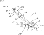
- the present invention relates to a door-opening device 1 for application to joinery of the door or window type.
- a window 2 comprising an opening 3 mounted, in this case, pivoting about a vertical axis on a frame 4.
- This carpentry in this case this window 2 is equipped with a locking fitting 5, in the form of an espagnolette or locking espagnolette, located in the rebate of the opening 3.
- This locking fitting 5 comprises a control mechanism 6 acting on one or more operating rods 6A (visible in the figure 2 And 3 ) extending along the front upright 7 of the opening 3, or even the upper and lower crossbar(s) 8.
- the door opener device 1 is installed in the carpentry rebate at the level of the upper crosspiece 9 of the frame 4.
- This opener device 1 comprises a fixing base 10 having a first application side 11 intended to be attached to the carpentry rebate.
- this fixing base 10 is attached to the rebate of the upper crosspiece 9 of the frame 4.
- the fixing base 10 would preferably be attached to the opening.
- the present invention is therefore not limited to the example of layout illustrated in the figures.
- This fixing base 10 further comprises a second opposite side 12 on which a first end 15 of a half-opening arm 16 is mounted articulated around a pivot axis 13, perpendicular to the plane 14 of said fixing base 10.
- the opener arm 16 by pivoting around of the axis 13, starts from a position substantially parallel to the longitudinal axis 17 to extend in a plane perpendicular to that P of this carpentry 2.
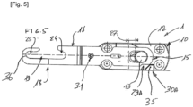
- This opening arm 16 is also provided, in an end portion 18 opposite the first end 15, with a slot 19 of oblong shape. It is defined to accommodate a hooking member 20, preferably, in the form of a T-shaped roller. , conversely, on frame 4 or sash 3.
- This attachment member 20 is defined as movable in translation under the impetus of an operating rod 6A actuated by the control mechanism 6 of the locking fitting 5.
- this attachment member 20 is capable of occupying, preferably, at least one locked position 21 and, successively starting from the latter, at least two distinct positions, including a first and a second unlocked position 22, 23.
- the slot 19 advantageously comprises an exhaust opening 240 through which the attachment member 20 can disengage laterally, substantially in a direction perpendicular to the plane P of the carpentry 2, when this attachment member 20 occupies the first unlocking position 22, between the locked position 21 and the unlocking position 23, as shown in the picture 3 .
- the opening 19 in the cracking arm 16 describes notches 24, 25, one of which 24 is closer to the first end 15 of this cracking arm 16 and a notch 25 more distant.
- the opening arm 16 is still mounted so as to be able to move in a longitudinal direction 26, perpendicular to the pivot axis 13, according to a stroke of defined length 27.
- the opening arm 16 can be provided with an oblong slot through which it is mounted on the pivot pin 13.
- the opening arm 16 is capable of being pushed back longitudinally from a rotationally locked position 28 with respect to the fixing base 10 into a position of free rotation around the pivot axis 13 and vice versa.
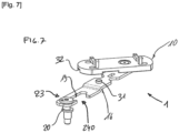
- the half-opening arm 16 comprises rotation locking means 29 capable of cooperating with complementary locking means 30 provided at the level of the fixing base 10.
- the rotation blocking means 29 are defined by a roller 31 extending under the opening arm 16 in the direction of the fixing base 10.
- This roller 31 is defined able to engage in a notch in form of striker 32 that this fixing base 10 comprises as complementary locking means 30, this when said opening arm 16 is pushed back into its rotation locking position 28.
- these rotation locking means 29 and the complementary locking means 30 are able to cooperate with each other when the opening arm 16 is brought into its locking position 28 by longitudinal movement, but, in addition , on the condition that the opening arm 16 is in an angular position 33 defined with respect to the fixing base 10.
- This angular position 33 is that occupied by this opening arm 16 in its inactive position, it that is to say in a plane substantially parallel to that of the carpentry 2, or substantially in the longitudinal alignment of the fixing base 10.
- This angular position 33 is in particular that occupied by this half-opening arm 16 when the window 2 is closed, that is to say when the opening 3 is pushed back against the fixed frame 4.
- the locking fitting 5 is capable of being actuated, in particular to lock the leaf 3 on the fixed frame 4.
- This action causes the attachment member 20 to reach its locked position 21 by engaging in the notch 24 of the light 19. It is finally under the action of this attachment member 20, pushed back into the locked position 21, and its interaction with the bottom 34 of this notch 24 that the half-opening arm 16 is pushed back into its blocking position 28 by movement perpendicular to the pivot axis 13 and engagement of the roller 31 in the notch in the form of a striker 32.
- the stroke 27 in the longitudinal direction 26 of the half-opening arm 16, perpendicular to the pivot axis 13, is greater than the stroke necessary to pass from the position 28 of blocking in rotation of this opening arm 16 with respect to the fixing base 10, in a free position in rotation around the pivot axis 13.
- this interlocking device 1 may have the additional function of compression, at least of compression adjustment of the leaf 3 against the fixed frame 4 in the locked position of the locking fitting 5.
- the roller 31 is mounted in eccentric rotation on the opening arm 16, allowing it to be adjusted at least in a direction transverse to the longitudinal direction 26 on this opening arm 16.
- this one in cooperation with the notch in the form of a striker 32, can, by action on said opening arm 16, result in pulling the sash 3 against the fixed frame 4.
- the first end 15 of the opening arm 16 can form rotation blocking means 29A capable of cooperating, in the blocking position 18 of said opening arm 16, with blocking means complementary 30A in the form of a stop 35 that comprises the fixing base 10, on its side 12 on which is pivotally mounted the opening arm 16.
- This stop 35 is installed in such a way that in this blocking position 28 the first end 15 of the half-opening arm 16 extends in line with this stop 35 so as to prevent rotation of the latter. On the contrary, moved away from this blocking position 28, this first end 15 of the opening arm 16 escapes the action of the stop 35 allowing the free rotation of this arm 16.
- the half-opening arm 16 can, in particular when it is arranged in the longitudinal alignment of the fixing base 10, be pushed back into the position of blocking 28 by the attachment member 20 whose movement is controlled by the locking fitting 5. Conversely, during an unlocking command of the latter, this attachment member 20 can control the longitudinal movement of this arm opening 16 to release it from this blocking position 28.
- this attachment member 20 essentially comes out of the notch 24 to position itself in line with the opening of escapement 240 that the slot 19 comprises in the end portion 18 of the half-opening arm 16, in its travel between this first unlocking position 22 and the second unlocking position 23, the hooking member 20 engages in the notch 25 of this slot 19.
- the attachment member 20 pushes the arm ajar 16 in an unlocking direction 37 which has the function of disengaging the roller 31 from the notch in the form of a striker 32. In the embodiment shown and described here by way of example, this action also has the consequence of disengaging the first end 15 of this opening arm 16 of the stop 34.
- the ajar device 1 further comprises elastic return means 38 defined to return the ajar arm 16 by rotation to the longitudinal extension of the fixing base 10 from an angular position separated of this axis.
- elastic return means 38 have the essential function of bringing the opening arm 16 back to an inactive position, substantially in the plane of the carpentry in the event that it were moved away from it other than through the hooking member 20.
- this can occur when an opening control for free rotation of the sash 3 relative to the fixed frame 4 has been requested through the locking fitting 5.
- the attachment member 20, pushed back into its first unlocking position 22 can escape the half-opening arm 16 allowing the user to open his door or window widely.
- the ajar device 1, then freely accessible in the rebate, can be voluntarily or involuntarily actuated and the ajar arm 16 can be moved away from the plane P of the carpentry 2. This ajar arm 16 can subsequently prevent the opening 3 to close on the fixed frame 4, or even twist during this action.
- the elastic return means 38 interacting between the fixing base 10 and the opening arm 16 remedy this risk.
- These elastic return means 38 can take different embodiments. Their restoring force is preferably limited to their function, that is to say capable of bringing the half-opening arm 16 back into this inactive position, without opposing the half-opening of the door or window.
Landscapes
- Engineering & Computer Science (AREA)
- Mechanical Engineering (AREA)
- Wing Frames And Configurations (AREA)
Claims (12)
- Feststellvorrichtung, die eine Befestigungsbasis (10) aufweist, umfassend eine erste Seite (11) zum Aufbringen in einem Falz einer Zarge (4) oder eines Flügels (3) einer Schreinerarbeit (2), der Art Tür oder Fenster, und eine zweite gegenüberliegende Seite (12), auf die um eine Schwenkachse (13) herum senkrecht zu der Ebene der Befestigungsbasis (10) ein erstes Ende (15) eines Feststellarms (16) gelenkig montiert ist, der in einem gegenüberliegenden Endteil (18) mit einer Längsöffnung (19) versehen ist, die zum Aufnehmen eines Verhakungsfingers (20) definiert ist, der jeweils den Flügel (3) oder die Zarge (4) ausrüstet, dadurch gekennzeichnet, dass an seinem ersten Ende (15), das auf der Befestigungsbasis (10) schwenkbar montiert ist, der Feststellarm (16) außerdem in seiner Längsrichtung (26) senkrecht zu der Schwenkachse (13) gemäß einem definierten Längshub (27) bewegbar montiert ist.
- Feststellvorrichtung nach Anspruch 1 dadurch gekennzeichnet, dass der Schlitz (19) eine Auslassöffnung (240) aufweist, die zum Ermöglichen des seitlichen Auslösens senkrecht zu der Längsrichtung (26) des Verhakungselements (20) auf beiden Seiten dieser Auslassöffnung (240) definiert ist, wobei der Schlitz (19) Kerben (24, 25) aufweist, von denen die eine (24) näher an dem ersten Ende (15) dieses Feststellarms (16) und eine Kerbe (25) weiter entfernt ist.
- Feststellvorrichtung nach den vorstehenden Ansprüchen,
dadurch gekennzeichnet, dass der Feststellarm (16) definiert ist, um in Längsrichtung von einer Drehsicherungsposition (28) relativ zu der Befestigungsbasis (10) in eine frei drehbare Position um die Schwenkachse (13) herum und umgekehrt zurückgeschoben zu werden. - Feststellvorrichtung nach Anspruch 1 und 3,
dadurch gekennzeichnet, dass der Hub (27) in der Längsrichtung (26) des Feststellarms (16) senkrecht zu der Schwenkachse (13) größer als der Hub zum Übergehen von seiner Drehsicherungsposition (28) in eine frei drehbare Position um die Schwenkachse (13) herum definiert ist. - Feststellvorrichtung nach Anspruch 3, dadurch gekennzeichnet, dass der Feststellarm (16) Drehsicherungsmittel (29); (29A) umfasst, die zum Zusammenwirken mit komplementären Sicherungsmitteln (30); (30A) geeignet sind, die an der Befestigungsbasis (10) vorgesehen sind.
- Feststellvorrichtung nach Anspruch 5, dadurch gekennzeichnet, dass Drehsicherungsmittel (29) und die komplementären Sicherungsmittel (30) so definiert sind, dass sie miteinander zusammenwirken, wenn sich der Feststellarm (16) in einer definierten Winkelposition (33) relativ zu der Befestigungsbasis (10) befindet.
- Feststellvorrichtung nach Anspruch 6, dadurch gekennzeichnet, dass die definierte Winkelposition (33) diejenige ist, die durch den Feststellarm (16) in seiner inaktiven Position eingenommen wird, im Wesentlichen in der Längsausrichtung der Befestigungsbasis (10).
- Feststellvorrichtung nach einem der Ansprüche 4 bis 7,
dadurch gekennzeichnet, dass die Drehsicherungsmittel (29) durch eine Rolle (31) definiert sind, die sich unter dem Feststellarm (16) in Richtung der Befestigungsbasis (10) erstreckt, wobei diese Rolle (31) zum Eingreifen in eine schließblechförmige Kerbe (32) definiert ist, die von dieser Befestigungsbasis (10) als ergänzendes Sicherungsmittel (30) aufgewiesen ist, dies wenn der Feststellarm (16) in seine Drehsicherungsposition (28) zurückgeschoben wird. - Feststellvorrichtung nach Anspruch 8, dadurch gekennzeichnet, dass die Rolle (31) auf dem Feststellarm (16) für ihre Einstellung mindestens entlang einer Querrichtung relativ zu der Längsrichtung (26) dieses Feststellarms (16) exzentrisch drehbar montiert ist.
- Feststellvorrichtung nach einem der Ansprüche 4 bis 7,
dadurch gekennzeichnet, dass die Drehsicherungsmittel (29A) durch das erste Ende (15) des Feststellarms (16) definiert sind, um geeignet zu sein, in der Sicherungsposition (28) dieses letzteren mit komplementären Sicherungsmitteln (30A) in Form eines Anschlags (35), der von der Befestigungsbasis (10) aufgewiesen ist, auf ihrer Seite (12), auf der der Feststellarm (16) schwenkbar montiert ist, zusammenzuwirken. - Feststellvorrichtung nach einem der vorstehenden Ansprüche,
dadurch gekennzeichnet, dass sie elastische Rückstellmittel (38) aufweist, die zum Zurückbringen durch Drehung des Feststellarms (16) in die Längsverlängerung der Befestigungsbasis (10) von einer auseinanderstehenden Winkelposition dieser Achse definiert ist. - Schreinerarbeit der Art Tür oder Fenster, umfassend mindestens einen Flügel, der an einer Zarge montiert ist und mit einem Verriegelungsbeschlag ausgerüstet ist, wie einem Treibstangengetriebe oder einem Treibstangenschloss, der in dem Falz des Flügels (3) oder der Zarge (4) eingesetzt ist, und ein Verhakungselement (20) aufweist, das unter dem Impuls einer Betätigungsstange (6A) translatorisch bewegbar ist, die durch einen Steuermechanismus (6) des Verriegelungsbeschlags (5) in Gang gesetzt wird, zum Einnehmen mindestens einer verriegelten Position (21) und nacheinander aus dieser, mindestens zwei separater Positionen, die eine erste und eine zweite Entriegelungsposition (22), (23) sind, dadurch gekennzeichnet, dass sie eine Feststellvorrichtung (1) nach einem der Ansprüche 1 bis 11 umfasst, deren Längsöffnung (19) zum Aufnehmen des Verhakungsfingers (20) definiert ist.
Priority Applications (1)
| Application Number | Priority Date | Filing Date | Title |
|---|---|---|---|
| EP20211745.3A EP4008863B1 (de) | 2020-12-04 | 2020-12-04 | Tür- und fensterspaltsicherung |
Applications Claiming Priority (1)
| Application Number | Priority Date | Filing Date | Title |
|---|---|---|---|
| EP20211745.3A EP4008863B1 (de) | 2020-12-04 | 2020-12-04 | Tür- und fensterspaltsicherung |
Publications (3)
| Publication Number | Publication Date |
|---|---|
| EP4008863A1 EP4008863A1 (de) | 2022-06-08 |
| EP4008863B1 true EP4008863B1 (de) | 2023-08-02 |
| EP4008863C0 EP4008863C0 (de) | 2023-08-02 |
Family
ID=73726574
Family Applications (1)
| Application Number | Title | Priority Date | Filing Date |
|---|---|---|---|
| EP20211745.3A Active EP4008863B1 (de) | 2020-12-04 | 2020-12-04 | Tür- und fensterspaltsicherung |
Country Status (1)
| Country | Link |
|---|---|
| EP (1) | EP4008863B1 (de) |
Family Cites Families (6)
| Publication number | Priority date | Publication date | Assignee | Title |
|---|---|---|---|---|
| BE1009024A4 (fr) * | 1995-01-12 | 1996-10-01 | Metalchimex S A | Entrebailleur d'un vantail oscillobattant d'une menuiserie metallique. |
| DE69625331T2 (de) * | 1996-04-30 | 2003-10-16 | Ferco International Ferrures Et Serrures De Batiment S.A., Sarrebourg | Feststeller für Tür, Fenster oder sonstiges |
| GB2384270B (en) * | 2000-10-19 | 2004-03-10 | Interlock Group Ltd | A restrictor device |
| TR200807184A2 (tr) * | 2008-09-22 | 2009-12-21 | Külekçi̇ Aydin | Yandan havalandırmalı otomatik tek açılım ispanyolet |
| FR2995623B1 (fr) | 2012-09-18 | 2014-10-10 | Ferco | Procede et dispositif de commande de ferrure de verrouillage |
| DE102014226794A1 (de) | 2014-12-22 | 2016-06-23 | Roto Frank Ag | Beschlag zum Einbau zwischen einem Flügel und einem festen Rahmen eines Fensters, einer Tür oder dergleichen sowie Fenster, Tür oder dergleichen mit einem derartigen Beschlag |
-
2020
- 2020-12-04 EP EP20211745.3A patent/EP4008863B1/de active Active
Also Published As
| Publication number | Publication date |
|---|---|
| EP4008863C0 (de) | 2023-08-02 |
| EP4008863A1 (de) | 2022-06-08 |
Similar Documents
| Publication | Publication Date | Title |
|---|---|---|
| EP0770751B1 (de) | Anlage um einen Flügel angelehnt zu halten | |
| EP4008863B1 (de) | Tür- und fensterspaltsicherung | |
| EP0928868B1 (de) | Gleitstangenverschluss oder Gleitstangenschloss für Tür, Fenster oder dergleichen | |
| EP1004737B1 (de) | Anhebevorrichtung für den Flügel einer Tür , eines Fensters oder dergleichen | |
| EP2586943B1 (de) | Feststell- und Sicherheitsvorrichtung für Tür oder Fenster | |
| EP4361388B1 (de) | Verriegelungssystem für eine schiebetür | |
| EP2112303B1 (de) | Vorrichtung zur Verhinderung von Fehlbedienung und Treibstangenverriegelungsbeschlag für eine Schiebetür | |
| EP0805250B1 (de) | Feststeller für Tür, Fenster oder sonstiges | |
| EP0742333B1 (de) | Aussteller für Türe, Fenster oder sonstiges | |
| EP1241307B1 (de) | Feststeller für Tür, Fenster dgl. mit treibstangenverschlussartigen Beschlag | |
| FR2729429A1 (fr) | Entrebailleur pour fenetre, porte-fenetre ou analogue | |
| FR3024994A1 (fr) | Dispositif de commande de ferrure de verrouillage de type cremone ou cremone-serrure | |
| FR3096067A1 (fr) | Dispositif de poignée de commande à levier | |
| EP1878862B1 (de) | Verriegelungseinrichtung für einen Flügel | |
| EP1164244A2 (de) | Anhebevorrichtung für den Flügel einer Tür, eines Fensters oder dergleichen | |
| EP2907947A1 (de) | Verriegelungsvorrichtung für halbfesten Fenster- oder Türflügel | |
| FR2825111A1 (fr) | Verrou entrebailleur de porte, fenetre ou analogue | |
| FR3099196A1 (fr) | Ferrure de verrouillage à moyens de rappel élastique en position verrouillée. | |
| FR2825400A1 (fr) | Verrou pour vantail de porte, fenetre ou similaire | |
| EP0743414A1 (de) | Austellvorrichtung für zweiflügelige Fenster, Türe oder dergleichen | |
| EP1362972A1 (de) | Verriegelungsbeschlag für zweiflügelige Tür, Fenster od. dgl. ohne Mittelpfosten | |
| EP1270857A1 (de) | Feststell- und Sicherheitsvorrichtung für einen verschiebbaren Flügel einer Tür, eines Fensters oder dgl. | |
| FR2825401A1 (fr) | Verrou pour vantail de porte, fenetre ou similaire | |
| FR3097581A1 (fr) | Boitier de serrure à verrouillage automatique | |
| EP3091154A1 (de) | Ausrückbarer schliessbügel |
Legal Events
| Date | Code | Title | Description |
|---|---|---|---|
| PUAI | Public reference made under article 153(3) epc to a published international application that has entered the european phase |
Free format text: ORIGINAL CODE: 0009012 |
|
| STAA | Information on the status of an ep patent application or granted ep patent |
Free format text: STATUS: THE APPLICATION HAS BEEN PUBLISHED |
|
| AK | Designated contracting states |
Kind code of ref document: A1 Designated state(s): AL AT BE BG CH CY CZ DE DK EE ES FI FR GB GR HR HU IE IS IT LI LT LU LV MC MK MT NL NO PL PT RO RS SE SI SK SM TR |
|
| STAA | Information on the status of an ep patent application or granted ep patent |
Free format text: STATUS: REQUEST FOR EXAMINATION WAS MADE |
|
| 17P | Request for examination filed |
Effective date: 20221116 |
|
| RBV | Designated contracting states (corrected) |
Designated state(s): AL AT BE BG CH CY CZ DE DK EE ES FI FR GB GR HR HU IE IS IT LI LT LU LV MC MK MT NL NO PL PT RO RS SE SI SK SM TR |
|
| RIC1 | Information provided on ipc code assigned before grant |
Ipc: E05C 17/16 20060101ALI20230302BHEP Ipc: E05C 9/18 20060101ALI20230302BHEP Ipc: E05C 9/06 20060101ALI20230302BHEP Ipc: E05B 17/20 20060101AFI20230302BHEP |
|
| GRAP | Despatch of communication of intention to grant a patent |
Free format text: ORIGINAL CODE: EPIDOSNIGR1 |
|
| STAA | Information on the status of an ep patent application or granted ep patent |
Free format text: STATUS: GRANT OF PATENT IS INTENDED |
|
| INTG | Intention to grant announced |
Effective date: 20230413 |
|
| GRAS | Grant fee paid |
Free format text: ORIGINAL CODE: EPIDOSNIGR3 |
|
| GRAA | (expected) grant |
Free format text: ORIGINAL CODE: 0009210 |
|
| STAA | Information on the status of an ep patent application or granted ep patent |
Free format text: STATUS: THE PATENT HAS BEEN GRANTED |
|
| AK | Designated contracting states |
Kind code of ref document: B1 Designated state(s): AL AT BE BG CH CY CZ DE DK EE ES FI FR GB GR HR HU IE IS IT LI LT LU LV MC MK MT NL NO PL PT RO RS SE SI SK SM TR |
|
| REG | Reference to a national code |
Ref country code: GB Ref legal event code: FG4D Free format text: NOT ENGLISH |
|
| REG | Reference to a national code |
Ref country code: CH Ref legal event code: EP |
|
| REG | Reference to a national code |
Ref country code: DE Ref legal event code: R096 Ref document number: 602020014874 Country of ref document: DE |
|
| P01 | Opt-out of the competence of the unified patent court (upc) registered |
Effective date: 20230720 |
|
| REG | Reference to a national code |
Ref country code: IE Ref legal event code: FG4D Free format text: LANGUAGE OF EP DOCUMENT: FRENCH |
|
| U01 | Request for unitary effect filed |
Effective date: 20230809 |
|
| U07 | Unitary effect registered |
Designated state(s): AT BE BG DE DK EE FI FR IT LT LU LV MT NL PT SE SI Effective date: 20230816 |
|
| P04 | Withdrawal of opt-out of the competence of the unified patent court (upc) registered |
Effective date: 20230811 |
|
| PG25 | Lapsed in a contracting state [announced via postgrant information from national office to epo] |
Ref country code: GR Free format text: LAPSE BECAUSE OF FAILURE TO SUBMIT A TRANSLATION OF THE DESCRIPTION OR TO PAY THE FEE WITHIN THE PRESCRIBED TIME-LIMIT Effective date: 20231103 |
|
| PG25 | Lapsed in a contracting state [announced via postgrant information from national office to epo] |
Ref country code: IS Free format text: LAPSE BECAUSE OF FAILURE TO SUBMIT A TRANSLATION OF THE DESCRIPTION OR TO PAY THE FEE WITHIN THE PRESCRIBED TIME-LIMIT Effective date: 20231202 |
|
| PG25 | Lapsed in a contracting state [announced via postgrant information from national office to epo] |
Ref country code: RS Free format text: LAPSE BECAUSE OF FAILURE TO SUBMIT A TRANSLATION OF THE DESCRIPTION OR TO PAY THE FEE WITHIN THE PRESCRIBED TIME-LIMIT Effective date: 20230802 Ref country code: NO Free format text: LAPSE BECAUSE OF FAILURE TO SUBMIT A TRANSLATION OF THE DESCRIPTION OR TO PAY THE FEE WITHIN THE PRESCRIBED TIME-LIMIT Effective date: 20231102 Ref country code: IS Free format text: LAPSE BECAUSE OF FAILURE TO SUBMIT A TRANSLATION OF THE DESCRIPTION OR TO PAY THE FEE WITHIN THE PRESCRIBED TIME-LIMIT Effective date: 20231202 Ref country code: HR Free format text: LAPSE BECAUSE OF FAILURE TO SUBMIT A TRANSLATION OF THE DESCRIPTION OR TO PAY THE FEE WITHIN THE PRESCRIBED TIME-LIMIT Effective date: 20230802 Ref country code: GR Free format text: LAPSE BECAUSE OF FAILURE TO SUBMIT A TRANSLATION OF THE DESCRIPTION OR TO PAY THE FEE WITHIN THE PRESCRIBED TIME-LIMIT Effective date: 20231103 |
|
| U20 | Renewal fee for the european patent with unitary effect paid |
Year of fee payment: 4 Effective date: 20231227 |
|
| PG25 | Lapsed in a contracting state [announced via postgrant information from national office to epo] |
Ref country code: PL Free format text: LAPSE BECAUSE OF FAILURE TO SUBMIT A TRANSLATION OF THE DESCRIPTION OR TO PAY THE FEE WITHIN THE PRESCRIBED TIME-LIMIT Effective date: 20230802 |
|
| PG25 | Lapsed in a contracting state [announced via postgrant information from national office to epo] |
Ref country code: ES Free format text: LAPSE BECAUSE OF FAILURE TO SUBMIT A TRANSLATION OF THE DESCRIPTION OR TO PAY THE FEE WITHIN THE PRESCRIBED TIME-LIMIT Effective date: 20230802 |
|
| PG25 | Lapsed in a contracting state [announced via postgrant information from national office to epo] |
Ref country code: SM Free format text: LAPSE BECAUSE OF FAILURE TO SUBMIT A TRANSLATION OF THE DESCRIPTION OR TO PAY THE FEE WITHIN THE PRESCRIBED TIME-LIMIT Effective date: 20230802 Ref country code: RO Free format text: LAPSE BECAUSE OF FAILURE TO SUBMIT A TRANSLATION OF THE DESCRIPTION OR TO PAY THE FEE WITHIN THE PRESCRIBED TIME-LIMIT Effective date: 20230802 Ref country code: ES Free format text: LAPSE BECAUSE OF FAILURE TO SUBMIT A TRANSLATION OF THE DESCRIPTION OR TO PAY THE FEE WITHIN THE PRESCRIBED TIME-LIMIT Effective date: 20230802 Ref country code: CZ Free format text: LAPSE BECAUSE OF FAILURE TO SUBMIT A TRANSLATION OF THE DESCRIPTION OR TO PAY THE FEE WITHIN THE PRESCRIBED TIME-LIMIT Effective date: 20230802 Ref country code: SK Free format text: LAPSE BECAUSE OF FAILURE TO SUBMIT A TRANSLATION OF THE DESCRIPTION OR TO PAY THE FEE WITHIN THE PRESCRIBED TIME-LIMIT Effective date: 20230802 |
|
| REG | Reference to a national code |
Ref country code: DE Ref legal event code: R097 Ref document number: 602020014874 Country of ref document: DE |
|
| PLBE | No opposition filed within time limit |
Free format text: ORIGINAL CODE: 0009261 |
|
| STAA | Information on the status of an ep patent application or granted ep patent |
Free format text: STATUS: NO OPPOSITION FILED WITHIN TIME LIMIT |
|
| 26N | No opposition filed |
Effective date: 20240503 |
|
| REG | Reference to a national code |
Ref country code: CH Ref legal event code: PL |
|
| PG25 | Lapsed in a contracting state [announced via postgrant information from national office to epo] |
Ref country code: MC Free format text: LAPSE BECAUSE OF FAILURE TO SUBMIT A TRANSLATION OF THE DESCRIPTION OR TO PAY THE FEE WITHIN THE PRESCRIBED TIME-LIMIT Effective date: 20230802 |
|
| PG25 | Lapsed in a contracting state [announced via postgrant information from national office to epo] |
Ref country code: MC Free format text: LAPSE BECAUSE OF FAILURE TO SUBMIT A TRANSLATION OF THE DESCRIPTION OR TO PAY THE FEE WITHIN THE PRESCRIBED TIME-LIMIT Effective date: 20230802 |
|
| REG | Reference to a national code |
Ref country code: IE Ref legal event code: MM4A |
|
| PG25 | Lapsed in a contracting state [announced via postgrant information from national office to epo] |
Ref country code: IE Free format text: LAPSE BECAUSE OF NON-PAYMENT OF DUE FEES Effective date: 20231204 |
|
| PG25 | Lapsed in a contracting state [announced via postgrant information from national office to epo] |
Ref country code: CH Free format text: LAPSE BECAUSE OF NON-PAYMENT OF DUE FEES Effective date: 20231231 |
|
| PG25 | Lapsed in a contracting state [announced via postgrant information from national office to epo] |
Ref country code: IE Free format text: LAPSE BECAUSE OF NON-PAYMENT OF DUE FEES Effective date: 20231204 Ref country code: CH Free format text: LAPSE BECAUSE OF NON-PAYMENT OF DUE FEES Effective date: 20231231 |
|
| P05 | Withdrawal of opt-out of the competence of the unified patent court (upc) changed |
Free format text: CASE NUMBER: APP_561106/2023 Effective date: 20230816 |
|
| U20 | Renewal fee for the european patent with unitary effect paid |
Year of fee payment: 5 Effective date: 20241227 |
|
| PG25 | Lapsed in a contracting state [announced via postgrant information from national office to epo] |
Ref country code: CY Free format text: LAPSE BECAUSE OF FAILURE TO SUBMIT A TRANSLATION OF THE DESCRIPTION OR TO PAY THE FEE WITHIN THE PRESCRIBED TIME-LIMIT; INVALID AB INITIO Effective date: 20201204 |
|
| PG25 | Lapsed in a contracting state [announced via postgrant information from national office to epo] |
Ref country code: HU Free format text: LAPSE BECAUSE OF FAILURE TO SUBMIT A TRANSLATION OF THE DESCRIPTION OR TO PAY THE FEE WITHIN THE PRESCRIBED TIME-LIMIT; INVALID AB INITIO Effective date: 20201204 |
|
| GBPC | Gb: european patent ceased through non-payment of renewal fee |
Effective date: 20241204 |
|
| PG25 | Lapsed in a contracting state [announced via postgrant information from national office to epo] |
Ref country code: GB Free format text: LAPSE BECAUSE OF NON-PAYMENT OF DUE FEES Effective date: 20241204 |
|
| PG25 | Lapsed in a contracting state [announced via postgrant information from national office to epo] |
Ref country code: TR Free format text: LAPSE BECAUSE OF FAILURE TO SUBMIT A TRANSLATION OF THE DESCRIPTION OR TO PAY THE FEE WITHIN THE PRESCRIBED TIME-LIMIT Effective date: 20230802 |
|
| U20 | Renewal fee for the european patent with unitary effect paid |
Year of fee payment: 6 Effective date: 20251230 |