EP4008900B1 - Capteurs de charge dans des éoliennes - Google Patents
Capteurs de charge dans des éoliennes Download PDFInfo
- Publication number
- EP4008900B1 EP4008900B1 EP20383053.4A EP20383053A EP4008900B1 EP 4008900 B1 EP4008900 B1 EP 4008900B1 EP 20383053 A EP20383053 A EP 20383053A EP 4008900 B1 EP4008900 B1 EP 4008900B1
- Authority
- EP
- European Patent Office
- Prior art keywords
- blades
- moments
- plane
- plane moments
- wind turbine
- Prior art date
- Legal status (The legal status is an assumption and is not a legal conclusion. Google has not performed a legal analysis and makes no representation as to the accuracy of the status listed.)
- Active
Links
Images





Classifications
-
- F—MECHANICAL ENGINEERING; LIGHTING; HEATING; WEAPONS; BLASTING
- F03—MACHINES OR ENGINES FOR LIQUIDS; WIND, SPRING, OR WEIGHT MOTORS; PRODUCING MECHANICAL POWER OR A REACTIVE PROPULSIVE THRUST, NOT OTHERWISE PROVIDED FOR
- F03D—WIND MOTORS
- F03D17/00—Monitoring or testing of wind motors, e.g. diagnostics
-
- F—MECHANICAL ENGINEERING; LIGHTING; HEATING; WEAPONS; BLASTING
- F03—MACHINES OR ENGINES FOR LIQUIDS; WIND, SPRING, OR WEIGHT MOTORS; PRODUCING MECHANICAL POWER OR A REACTIVE PROPULSIVE THRUST, NOT OTHERWISE PROVIDED FOR
- F03D—WIND MOTORS
- F03D80/00—Details, components or accessories not provided for in groups F03D1/00 - F03D17/00
-
- G—PHYSICS
- G01—MEASURING; TESTING
- G01L—MEASURING FORCE, STRESS, TORQUE, WORK, MECHANICAL POWER, MECHANICAL EFFICIENCY, OR FLUID PRESSURE
- G01L1/00—Measuring force or stress, in general
- G01L1/20—Measuring force or stress, in general by measuring variations in ohmic resistance of solid materials or of electrically-conductive fluids; by making use of electrokinetic cells, i.e. liquid-containing cells wherein an electrical potential is produced or varied upon the application of stress
- G01L1/22—Measuring force or stress, in general by measuring variations in ohmic resistance of solid materials or of electrically-conductive fluids; by making use of electrokinetic cells, i.e. liquid-containing cells wherein an electrical potential is produced or varied upon the application of stress using resistance strain gauges
-
- F—MECHANICAL ENGINEERING; LIGHTING; HEATING; WEAPONS; BLASTING
- F05—INDEXING SCHEMES RELATING TO ENGINES OR PUMPS IN VARIOUS SUBCLASSES OF CLASSES F01-F04
- F05B—INDEXING SCHEME RELATING TO WIND, SPRING, WEIGHT, INERTIA OR LIKE MOTORS, TO MACHINES OR ENGINES FOR LIQUIDS COVERED BY SUBCLASSES F03B, F03D AND F03G
- F05B2260/00—Function
- F05B2260/80—Diagnostics
-
- F—MECHANICAL ENGINEERING; LIGHTING; HEATING; WEAPONS; BLASTING
- F05—INDEXING SCHEMES RELATING TO ENGINES OR PUMPS IN VARIOUS SUBCLASSES OF CLASSES F01-F04
- F05B—INDEXING SCHEME RELATING TO WIND, SPRING, WEIGHT, INERTIA OR LIKE MOTORS, TO MACHINES OR ENGINES FOR LIQUIDS COVERED BY SUBCLASSES F03B, F03D AND F03G
- F05B2260/00—Function
- F05B2260/83—Testing, e.g. methods, components or tools therefor
-
- F—MECHANICAL ENGINEERING; LIGHTING; HEATING; WEAPONS; BLASTING
- F05—INDEXING SCHEMES RELATING TO ENGINES OR PUMPS IN VARIOUS SUBCLASSES OF CLASSES F01-F04
- F05B—INDEXING SCHEME RELATING TO WIND, SPRING, WEIGHT, INERTIA OR LIKE MOTORS, TO MACHINES OR ENGINES FOR LIQUIDS COVERED BY SUBCLASSES F03B, F03D AND F03G
- F05B2270/00—Control
- F05B2270/30—Control parameters, e.g. input parameters
- F05B2270/331—Mechanical loads
-
- F—MECHANICAL ENGINEERING; LIGHTING; HEATING; WEAPONS; BLASTING
- F05—INDEXING SCHEMES RELATING TO ENGINES OR PUMPS IN VARIOUS SUBCLASSES OF CLASSES F01-F04
- F05B—INDEXING SCHEME RELATING TO WIND, SPRING, WEIGHT, INERTIA OR LIKE MOTORS, TO MACHINES OR ENGINES FOR LIQUIDS COVERED BY SUBCLASSES F03B, F03D AND F03G
- F05B2270/00—Control
- F05B2270/30—Control parameters, e.g. input parameters
- F05B2270/332—Maximum loads or fatigue criteria
-
- F—MECHANICAL ENGINEERING; LIGHTING; HEATING; WEAPONS; BLASTING
- F05—INDEXING SCHEMES RELATING TO ENGINES OR PUMPS IN VARIOUS SUBCLASSES OF CLASSES F01-F04
- F05B—INDEXING SCHEME RELATING TO WIND, SPRING, WEIGHT, INERTIA OR LIKE MOTORS, TO MACHINES OR ENGINES FOR LIQUIDS COVERED BY SUBCLASSES F03B, F03D AND F03G
- F05B2270/00—Control
- F05B2270/80—Devices generating input signals, e.g. transducers, sensors, cameras or strain gauges
- F05B2270/808—Strain gauges; Load cells
-
- Y—GENERAL TAGGING OF NEW TECHNOLOGICAL DEVELOPMENTS; GENERAL TAGGING OF CROSS-SECTIONAL TECHNOLOGIES SPANNING OVER SEVERAL SECTIONS OF THE IPC; TECHNICAL SUBJECTS COVERED BY FORMER USPC CROSS-REFERENCE ART COLLECTIONS [XRACs] AND DIGESTS
- Y02—TECHNOLOGIES OR APPLICATIONS FOR MITIGATION OR ADAPTATION AGAINST CLIMATE CHANGE
- Y02E—REDUCTION OF GREENHOUSE GAS [GHG] EMISSIONS, RELATED TO ENERGY GENERATION, TRANSMISSION OR DISTRIBUTION
- Y02E10/00—Energy generation through renewable energy sources
- Y02E10/70—Wind energy
- Y02E10/72—Wind turbines with rotation axis in wind direction
Definitions
- the present disclosure relates to wind turbines, and more particularly relates to methods and systems for determining reliability or correct functioning of load sensors in a wind turbine.
- the present disclosure particularly relates to the determining the functioning of load sensors indicative of blade root bending moments.
- a wind turbine generally includes a tower with a nacelle supported on top of the tower.
- a wind turbine rotor comprising a hub and a plurality of wind turbine blades may be rotatably mounted to the nacelle.
- the wind turbine blades may be set in motion by wind.
- the hub of the wind turbine may be operatively coupled with a rotor of a generator. As the hub and blades rotate, the kinetic energy of the wind is converted to kinetic mechanical energy of the wind turbine rotor and ultimately to electrical energy or power in the generator.
- the generator may typically be arranged inside the nacelle.
- the wind turbine rotor may be coupled directly to the generator rotor in so-called direct drive wind turbines.
- the wind turbine rotor may include a main rotor shaft (a so-called "low speed shaft” which leads to a gearbox.
- a high-speed shaft of the gearbox may then drive the generator.
- the electrical power output of the generator may be fed to an electric grid.
- the connection of the generator to the grid may include e.g. a converter, transformer, medium voltage line and other.
- a wind turbine controller may be configured to determine suitable actuator setpoints for the wind turbine based on the prevailing circumstances.
- the actuator setpoints for modern variable speed wind turbines include e.g. the generator torque and the pitch angle of the blades. Through control of the pitch angle(s) of the blade(s) and the generator torque, the speed of the rotor may be controlled, as well as the electrical power output, aerodynamic thrust and further mechanical loads.
- the purpose of the control system is generally to maximize electrical power output while at the same time keeping loads in the wind turbine at an acceptable level.
- the actuator setpoints of torque and pitch may be changed in accordance with circumstances.
- important input for the determination of the actuator setpoints include e.g. wind speed, and wind direction.
- the wind speed may be measured directly or indirectly e.g. through the use of a (generator) rotor speed sensor.
- Wind turbines may also comprise load sensors on or in the blades for measuring loads on the blades caused by for example the wind and/or the weight of the blades. Too high loads on the blades can e.g. damage the blades and/or cause undesirable rotational speeds of the rotor which may damage other components of the wind turbine.
- the blade load sensors permit detecting high loads and make it possible to react, by e.g. acting on the pitch systems in such a way that loads on the blades may be reduced. These adjustments on the blades through the pitch systems may extend the life of the wind turbine and/or reduce the cost of producing power.
- Load sensors for measuring loads on wind turbines, and particularly wind turbine blades may include resistive strain gauges, fiber optic strain gauges or any other known strain sensing system. The performance of these kinds of sensors may degrade over time, under the influence of continuous loading, and under the influence of temperature changes, and from being exposed to different sorts of ambient conditions and environments.
- a spanwise direction refers to a direction along a longitudinal axis of the blade, extending from the blade root towards the blade tip.
- the edgewise direction refers to a direction along the chord of a section of the wind turbine blade, i.e. extending from leading edge to trailing edge.
- the flapwise direction is perpendicular to both the edgewise and the spanwise direction.
- loads may be decomposed as in-plane loads (loads that are tangential to the rotor plane) and out-of-plane loads (loads that are perpendicular to the rotor plane).
- the rotor plane may herein be defined as a plane perpendicular to the rotor rotational axis and passing through a center of the blades at the blade root.
- Blade load sensors can be calibrated in order to preserve their accuracy when taking measurements of the loads on the blades.
- Calibration normally comprises establishing correspondence between indications generated by the blade load sensors and values of reference according to calibration patterns (i.e. particular conditions for calibration). If the calibration process produces some inconsistency, suitable adjustments may be undertaken on the load sensors to improve their accuracy.
- blade load sensors can be manually calibrated in a factory by e.g. statically pulling the blades to obtain particular conditions for calibration. This manual calibration is normally performed before mounting the blades on the wind turbine. However, over time, load sensors may need to be recalibrated.
- EP 2 615 303 discloses a method of calibrating one or more load sensors of a blade of a wind turbine, wherein the wind turbine comprises: a main generator; a power electronic converter connected with the main generator; a rotor operationally connected with the main generator and carrying the blade. And the method being comprises: acting on the power electronic converter to operate the main generator as motor to set the blade in at least one predetermined condition; measuring loads in the predetermined condition using the load sensors of the blade; and calibrating the blade load sensors taking into account the measured loads.
- Such a method can be carried out particularly after interruption of normal operation of a wind turbine.
- blade load sensors can be manually calibrated when the blades are mounted on the wind turbine by manually (i.e. mechanically) acting on the wind turbine to e.g. set the blade in a particular position (e.g. horizontal position) with a particular pitch angle.
- This manual calibration permits recalibrating the load sensors regularly.
- this type of calibration may take a long time and may be especially expensive for offshore wind turbines because operators need to go where the wind turbine is located.
- the present disclosure provides examples of methods and systems for determining reliability or correct functioning of load sensors that resolve at least some of the aforementioned disadvantages.
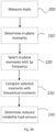
- a method for determining reliability of one or more load sensors in a wind turbine comprises, measuring loads with the load sensors during operation of the wind turbine and determining in-plane moments with rotor rotational speed frequency of one or more blades based on the measured loads. The method then further comprises comparing the in-plane moments with rotor rotational speed frequency with theoretical in-plane moments due to a mass of the blades and determining that the load sensors have reduced reliability if the in-plane moments with rotor rotational speed frequency deviate from the theoretical in-plane moments by more than a first threshold value
- the reliability or correct functioning of load sensors can be determined during operation of the wind turbine, i.e. the operation of the wind turbine does not need to be interrupted or put in specific conditions in order to be able to determine whether the load sensors are correctly indicating the loads.
- the loads measured may be measured as in-plane moments or converted to in-plane moments.
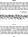
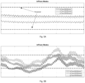
- the in-plane moments at any given moment during operation will be a combination of aerodynamic loads and loads due to mass of the blades.
- the mass of the blades will however provide the same moment throughout every rotation of the blade. At a 12 o'clock position and at a 6 o'clock position, the mass of the blade will not contribute to a bending moment.
Landscapes
- Engineering & Computer Science (AREA)
- Life Sciences & Earth Sciences (AREA)
- Sustainable Development (AREA)
- Sustainable Energy (AREA)
- Chemical & Material Sciences (AREA)
- Combustion & Propulsion (AREA)
- Mechanical Engineering (AREA)
- General Engineering & Computer Science (AREA)
- Physics & Mathematics (AREA)
- General Physics & Mathematics (AREA)
- Wind Motors (AREA)
Claims (15)
- Méthode pour déterminer la fiabilité d'un ou de plusieurs capteurs de charge dans une éolienne, comprenant :mesurer (200) les charges à l'aide des capteurs de charge pendant le fonctionnement de l'éolienne ;déterminer (210, 220) les moments dans le plan du rotor avec la fréquence de la vitesse de rotation du rotor d'une ou de plusieurs pales sur la base des charges mesuréesen comparant (230) les moments dans le plan du rotor avec la fréquence de la vitesse de rotation du rotor avec les moments théoriques dans le plan du rotor dus à la masse des pales ;déterminer (240) que les capteurs de charge ont une fiabilité réduite si les moments dans le plan du rotor avec la fréquence de la vitesse de rotation du rotor s'écartent des moments théoriques dans le plan du rotor de plus d'une première valeur seuil.
- La méthode selon la revendication 1, dans laquelle mesurer (200) des charges comprend mesurer (300) des moments dans le sens de battement et de la corde.
- La méthode selon la revendication 2, dans laquelle les moments dans le sens de battement et de la corde sont convertis (320) en moments dans le plan du rotor et en moments hors du plan du rotor sur la base d'un angle d'inclinaison des pales.
- La méthode selon l'une des revendications 1à 3, dans laquelle la détermination des moments dans le plan du rotor avec la fréquence de la vitesse de rotation du rotor comprenddéterminer (210) les moments dans le plan du rotor sur la base des charges mesurées ; etsélectionnant (220) les moments dans le plan du rotor en fonction de la fréquence de la vitesse de rotation du rotor.
- La méthode selon l'une des revendications 1 à 4, dans laquelle les moments théoriques dans le plan du rotor dus à la masse des pales sont déterminés sur la base d'une position azimutale de la pale du rotor
- Méthode selon l'une des revendications 1 à 5, dans laquelle la sélection des moments dans le plan du rotor en fonction de la fréquence de la vitesse de rotation du rotor comprend le filtrage (330) des moments dans le plan du rotor déterminés des pales à l'aide d'un filtre de crête.
- Méthode selon l'une des revendications 1 à 6, dans laquelle la valeur seuil est un pourcentage de la valeur absolue d'un moment théorique dans le plan du rotor.
- La méthode selon l'une des revendications 1 à 7, dans laquelle la comparaison des moments dans le plan du rotors sélectionnés avec les moments théoriques dans le plan du rotor dus à la masse des pales comprend la détermination d'une valeur moyenne quadratique des moments dans le plan du rotor sélectionnés.
- La méthode de l'une des revendications 1 à 8, comprenant en outre la génération d'un premier signal d'avertissement si les capteurs de charge ont une fiabilité réduite.
- La méthode de la revendication 9, comprenant en outre la détermination si les moments en plan du rotor sélectionnés des pales s'écartent des moments en plan du rotor théoriques des pales de plus d'une deuxième valeur seuil, la deuxième valeur seuil étant supérieure à la première valeur seuil.
- La méthode de la revendication 10, comprenant en outre l'interruption du fonctionnement de l'éolienne, si les moments en plan du rotor sélectionnés des pales s'écartent des moments en plan du rotor théoriques des pales de plus de la deuxième valeur seuil.
- Système de turbine éolienne comprenant :une éolienne (160) comprenant un rotor d'éolienne (115) avec plusieurs pales (120),une pluralité de capteurs de charge pour mesurer les charges sur les pales (120), etun système de contrôle configuré pour :recevoir les signaux des capteurs de charge pendant le fonctionnement ;déterminer les moments dans le plan du rotor (210) sur une ou plusieurs pales ;sélectionner (220) les moments dans le plan du rotor en fonction de la fréquence de la vitesse de rotation du rotor pour une ou plusieurs pales ;comparer (230) les moments en plan du rotor sélectionnés avec les moments en plan du rotor théoriques dus à la masse d'une ou de plusieurs pales ; etgénérer un signal d'avertissement si les moments dans le plan du rotor sélectionnés s'écartent des moments dans le plan du rotor théoriques de plus d'un seuil prédéfini.
- Le système de la revendication 12, dans lequel chacune des pales (120) comprend des jauges de contrainte.
- Le système de la revendication 12 ou 13, dans lequel les jauges de contrainte sont montées de manière à mesurer les charges dans le sens de la corde et de battement.
- Le système de l'une des revendications 12 à 14, dans lequel les capteurs sont montés dans ou près d'une partie de la racine des pales (120).
Priority Applications (7)
| Application Number | Priority Date | Filing Date | Title |
|---|---|---|---|
| PL20383053.4T PL4008900T3 (pl) | 2020-12-03 | 2020-12-03 | Czujniki obciążenia w turbinach wiatrowych |
| EP20383053.4A EP4008900B1 (fr) | 2020-12-03 | 2020-12-03 | Capteurs de charge dans des éoliennes |
| ES20383053T ES3023171T3 (en) | 2020-12-03 | 2020-12-03 | Load sensors in wind turbines |
| JP2021183805A JP7859809B2 (ja) | 2020-12-03 | 2021-11-11 | 風力タービンにおける負荷センサ |
| KR1020210168398A KR20220078498A (ko) | 2020-12-03 | 2021-11-30 | 풍력 터빈의 부하 센서 |
| US17/539,432 US11732696B2 (en) | 2020-12-03 | 2021-12-01 | Load sensors in wind turbines |
| CN202111471623.3A CN114593019A (zh) | 2020-12-03 | 2021-12-03 | 风力涡轮中的载荷传感器 |
Applications Claiming Priority (1)
| Application Number | Priority Date | Filing Date | Title |
|---|---|---|---|
| EP20383053.4A EP4008900B1 (fr) | 2020-12-03 | 2020-12-03 | Capteurs de charge dans des éoliennes |
Publications (2)
| Publication Number | Publication Date |
|---|---|
| EP4008900A1 EP4008900A1 (fr) | 2022-06-08 |
| EP4008900B1 true EP4008900B1 (fr) | 2025-01-29 |
Family
ID=73834412
Family Applications (1)
| Application Number | Title | Priority Date | Filing Date |
|---|---|---|---|
| EP20383053.4A Active EP4008900B1 (fr) | 2020-12-03 | 2020-12-03 | Capteurs de charge dans des éoliennes |
Country Status (7)
| Country | Link |
|---|---|
| US (1) | US11732696B2 (fr) |
| EP (1) | EP4008900B1 (fr) |
| JP (1) | JP7859809B2 (fr) |
| KR (1) | KR20220078498A (fr) |
| CN (1) | CN114593019A (fr) |
| ES (1) | ES3023171T3 (fr) |
| PL (1) | PL4008900T3 (fr) |
Families Citing this family (5)
| Publication number | Priority date | Publication date | Assignee | Title |
|---|---|---|---|---|
| DE102020105053A1 (de) * | 2020-02-26 | 2021-08-26 | fos4X GmbH | Verfahren zur Zustandsüberwachung eines Antriebsstrangs oder Turms einer Windenergieanlage und Windenergieanlage |
| EP4116582B1 (fr) * | 2021-07-05 | 2025-08-27 | General Electric Renovables España S.L. | Capteurs d'azimut dans des éoliennes |
| EP4273397B1 (fr) * | 2022-05-05 | 2025-02-19 | Wobben Properties GmbH | Procédé de détection d'un dysfonctionnement d'un capteur de charge d'une éolienne |
| GB202403773D0 (en) * | 2024-03-15 | 2024-05-01 | Insight Analytics Solutions Holdings Ltd | Wind turbine blade monitoring |
| WO2026114533A1 (fr) | 2024-11-26 | 2026-06-04 | Siemens Gamesa Renewable Energy A/S | Surveillance d'un moment de pale d'une pale de rotor |
Family Cites Families (31)
| Publication number | Priority date | Publication date | Assignee | Title |
|---|---|---|---|---|
| AU768212B2 (en) | 1999-11-03 | 2003-12-04 | Vestas Wind Systems A/S | Method of controlling the operation of a wind turbine and wind turbine for use in said method |
| DE10011393A1 (de) | 2000-03-09 | 2001-09-13 | Tacke Windenergie Gmbh | Regelungssystem für eine Windkraftanlage |
| CA2426711C (fr) | 2002-05-02 | 2009-11-17 | General Electric Company | Centrale eolienne, mecanisme de commande de centrale eolienne et methode d'exploitation d'une centrale eolienne |
| CA2651925A1 (fr) * | 2006-05-15 | 2007-11-22 | Igus-Innovative Technische Systeme Gmbh | Procede de surveillance des contraintes de pales de rotor d'eoliennes |
| DE102006036157B4 (de) | 2006-08-01 | 2016-09-15 | Senvion Gmbh | Kalibrierverfahren |
| US20090246019A1 (en) * | 2007-05-04 | 2009-10-01 | Mark Volanthen | Wind turbine monitoring |
| GB2458400B (en) * | 2007-05-04 | 2010-02-17 | Insensys Ltd | Wind turbine monitoring |
| US20110158806A1 (en) * | 2009-04-15 | 2011-06-30 | Arms Steven W | Wind Turbines and Other Rotating Structures with Instrumented Load-Sensor Bolts or Instrumented Load-Sensor Blades |
| EP2333322A3 (fr) * | 2009-11-30 | 2017-02-22 | Vestas Wind Systems A/S | Mesure des charges sur des pales d'éolienne |
| EP2354538A1 (fr) | 2010-02-01 | 2011-08-10 | Lm Glasfiber A/S | Procédé d'étalonnage des jauges de contrainte d'une pale d'éolienne |
| US8360722B2 (en) | 2010-05-28 | 2013-01-29 | General Electric Company | Method and system for validating wind turbine |
| DE102010052565A1 (de) * | 2010-11-25 | 2012-05-31 | Aloys Wobben | Verfahren zum Betreiben einer Windenergieanlage |
| US8463085B2 (en) * | 2010-12-17 | 2013-06-11 | General Electric Company | Systems and methods for monitoring a condition of a rotor blade for a wind turbine |
| US20110210551A1 (en) | 2011-02-07 | 2011-09-01 | Scholte-Wassink Hartmut | Method and system for testing a mechanical brake of a wind rotor shaft of a wind turbine |
| US8265885B2 (en) | 2011-06-24 | 2012-09-11 | General Electric Company | System and method for determining lifetime of wind turbine blade |
| US9447778B2 (en) * | 2011-11-02 | 2016-09-20 | Vestas Wind Systems A/S | Methods and systems for detecting sensor fault modes |
| US8757003B1 (en) * | 2011-12-15 | 2014-06-24 | Shaw Shahriar Makaremi | Multi-frequency-band blade condition monitoring system |
| US8511177B1 (en) * | 2011-12-15 | 2013-08-20 | Shaw Shahriar Makaremi | Blade condition monitoring system |
| ES2532177T3 (es) | 2012-01-12 | 2015-03-24 | Alstom Renewable Technologies | Calibración de sensores de carga en pala |
| EP3027895B1 (fr) * | 2013-07-30 | 2019-09-04 | Vestas Wind Systems A/S | Procédé et dispositif de fonctionnement de turbine éolienne basés sur des mesures de charge et d'accélération dans l'aube |
| EP3314120B1 (fr) * | 2015-06-24 | 2023-06-07 | Vestas Wind Systems A/S | Système de détection de charge de pale pour une éolienne |
| ES2885019T3 (es) * | 2015-06-24 | 2021-12-13 | Vestas Wind Sys As | Sistema de detección de carga de pala para una turbina eólica |
| US10612524B2 (en) * | 2015-06-30 | 2020-04-07 | Vestas Wind Systems A/S | Blade load sensing system for a wind turbine |
| US10605233B2 (en) * | 2015-06-30 | 2020-03-31 | Vestas Wind Systems A/S | Method of measuring load on a wind turbine |
| US10677225B2 (en) * | 2015-06-30 | 2020-06-09 | Vestas Wind Systems A/S | Method of calibrating load sensors of a wind turbine |
| JP6351557B2 (ja) * | 2015-09-11 | 2018-07-04 | 三菱重工業株式会社 | 荷重計測装置の較正方法、風車翼の荷重計測システム及び風車 |
| WO2017093512A1 (fr) * | 2015-12-03 | 2017-06-08 | Danmarks Tekniske Universitet | Surveillance de l'état d'un agencement de rotor, en particulier d'une éolienne |
| DE102017115926B4 (de) * | 2017-07-14 | 2022-03-17 | fos4X GmbH | Blattbiegemomentbestimmung mit zwei Lastsensoren pro Rotorblatt und unter Einbezug von Rotordaten |
| US10677765B2 (en) * | 2017-12-12 | 2020-06-09 | Honeywell International Inc. | Structural health monitoring of cyclically loaded structures |
| DE102018112825A1 (de) * | 2018-05-29 | 2019-12-05 | fos4X GmbH | Sensoranordnung für eine Windkraftanlage |
| US11168668B2 (en) * | 2019-06-24 | 2021-11-09 | Mistras Group, Inc. | Wind turbine blade monitoring systems |
-
2020
- 2020-12-03 EP EP20383053.4A patent/EP4008900B1/fr active Active
- 2020-12-03 ES ES20383053T patent/ES3023171T3/es active Active
- 2020-12-03 PL PL20383053.4T patent/PL4008900T3/pl unknown
-
2021
- 2021-11-11 JP JP2021183805A patent/JP7859809B2/ja active Active
- 2021-11-30 KR KR1020210168398A patent/KR20220078498A/ko active Pending
- 2021-12-01 US US17/539,432 patent/US11732696B2/en active Active
- 2021-12-03 CN CN202111471623.3A patent/CN114593019A/zh active Pending
Also Published As
| Publication number | Publication date |
|---|---|
| ES3023171T3 (en) | 2025-05-30 |
| CN114593019A (zh) | 2022-06-07 |
| JP7859809B2 (ja) | 2026-05-15 |
| KR20220078498A (ko) | 2022-06-10 |
| EP4008900A1 (fr) | 2022-06-08 |
| US11732696B2 (en) | 2023-08-22 |
| US20220178352A1 (en) | 2022-06-09 |
| JP2022089163A (ja) | 2022-06-15 |
| PL4008900T3 (pl) | 2025-05-19 |
Similar Documents
| Publication | Publication Date | Title |
|---|---|---|
| US11732696B2 (en) | Load sensors in wind turbines | |
| EP4116582B1 (fr) | Capteurs d'azimut dans des éoliennes | |
| DK177769B1 (en) | Methods and apparatus for detecting ice on a rotor vane | |
| EP2096300B1 (fr) | Procédé de controle du rapport de vitesse en bout de pales d'éoliennes | |
| EP3344870B1 (fr) | Éolienne et procédé de fonctionnement d'éolienne ayant une zone d'exclusion de vitesse de rotation | |
| EP3218600A1 (fr) | Système et procédé d'estimation de charges de pale de rotor d'une éolienne | |
| EP3663573B1 (fr) | Procédé pour réduire les vibrations dans des pales de rotor d'une éolienne | |
| EP4093967B1 (fr) | Système et procédé de commande d'éolienne | |
| US12037984B2 (en) | System and method for controlling blade pitch of wind turbine rotor blades to reduce vibrations and limit loads in a locked condition of the rotor hub | |
| EP3619425B1 (fr) | Facteur d'ajustement pour carte de performance aérodynamique | |
| US12152565B2 (en) | Vibrations in wind turbines | |
| EP3892850B1 (fr) | Système et procédé pour atténuer les charges agissant sur une pale de rotor d'une éolienne | |
| EP4194688A1 (fr) | Système et procédé de commande de pas de pale sur des pales de rotor d'éolienne pour réduire les vibrations et limiter les charges dans un état verrouillé du rotor d'éolienne | |
| JP6865672B2 (ja) | 風力発電装置の評価方法および設計方法 | |
| EP4467805A1 (fr) | Détection d'un déséquilibre de rotor dans une éolienne | |
| EP4343143A1 (fr) | Procédé et système de détection et d'atténuation de vibrations latérales dans des pales d'éolienne | |
| WO2025131318A1 (fr) | Détermination d'un déséquilibre de rotor aérodynamique dans une éolienne |
Legal Events
| Date | Code | Title | Description |
|---|---|---|---|
| PUAI | Public reference made under article 153(3) epc to a published international application that has entered the european phase |
Free format text: ORIGINAL CODE: 0009012 |
|
| STAA | Information on the status of an ep patent application or granted ep patent |
Free format text: STATUS: THE APPLICATION HAS BEEN PUBLISHED |
|
| AK | Designated contracting states |
Kind code of ref document: A1 Designated state(s): AL AT BE BG CH CY CZ DE DK EE ES FI FR GB GR HR HU IE IS IT LI LT LU LV MC MK MT NL NO PL PT RO RS SE SI SK SM TR |
|
| STAA | Information on the status of an ep patent application or granted ep patent |
Free format text: STATUS: EXAMINATION IS IN PROGRESS |
|
| 17P | Request for examination filed |
Effective date: 20221208 |
|
| 17Q | First examination report despatched |
Effective date: 20221216 |
|
| RBV | Designated contracting states (corrected) |
Designated state(s): AL AT BE BG CH CY CZ DE DK EE ES FI FR GB GR HR HU IE IS IT LI LT LU LV MC MK MT NL NO PL PT RO RS SE SI SK SM TR |
|
| P01 | Opt-out of the competence of the unified patent court (upc) registered |
Effective date: 20230529 |
|
| GRAP | Despatch of communication of intention to grant a patent |
Free format text: ORIGINAL CODE: EPIDOSNIGR1 |
|
| STAA | Information on the status of an ep patent application or granted ep patent |
Free format text: STATUS: GRANT OF PATENT IS INTENDED |
|
| INTG | Intention to grant announced |
Effective date: 20240625 |
|
| RAP3 | Party data changed (applicant data changed or rights of an application transferred) |
Owner name: GENERAL ELECTRIC RENOVABLES ESPANA S.L. |
|
| GRAS | Grant fee paid |
Free format text: ORIGINAL CODE: EPIDOSNIGR3 |
|
| GRAA | (expected) grant |
Free format text: ORIGINAL CODE: 0009210 |
|
| STAA | Information on the status of an ep patent application or granted ep patent |
Free format text: STATUS: THE PATENT HAS BEEN GRANTED |
|
| AK | Designated contracting states |
Kind code of ref document: B1 Designated state(s): AL AT BE BG CH CY CZ DE DK EE ES FI FR GB GR HR HU IE IS IT LI LT LU LV MC MK MT NL NO PL PT RO RS SE SI SK SM TR |
|
| REG | Reference to a national code |
Ref country code: GB Ref legal event code: FG4D |
|
| REG | Reference to a national code |
Ref country code: CH Ref legal event code: EP |
|
| REG | Reference to a national code |
Ref country code: DE Ref legal event code: R096 Ref document number: 602020045477 Country of ref document: DE |
|
| REG | Reference to a national code |
Ref country code: IE Ref legal event code: FG4D |
|
| REG | Reference to a national code |
Ref country code: NL Ref legal event code: FP |
|
| REG | Reference to a national code |
Ref country code: ES Ref legal event code: FG2A Ref document number: 3023171 Country of ref document: ES Kind code of ref document: T3 Effective date: 20250530 |
|
| PG25 | Lapsed in a contracting state [announced via postgrant information from national office to epo] |
Ref country code: RS Free format text: LAPSE BECAUSE OF FAILURE TO SUBMIT A TRANSLATION OF THE DESCRIPTION OR TO PAY THE FEE WITHIN THE PRESCRIBED TIME-LIMIT Effective date: 20250429 |
|
| PG25 | Lapsed in a contracting state [announced via postgrant information from national office to epo] |
Ref country code: FI Free format text: LAPSE BECAUSE OF FAILURE TO SUBMIT A TRANSLATION OF THE DESCRIPTION OR TO PAY THE FEE WITHIN THE PRESCRIBED TIME-LIMIT Effective date: 20250129 |
|
| REG | Reference to a national code |
Ref country code: LT Ref legal event code: MG9D |
|
| PG25 | Lapsed in a contracting state [announced via postgrant information from national office to epo] |
Ref country code: IS Free format text: LAPSE BECAUSE OF FAILURE TO SUBMIT A TRANSLATION OF THE DESCRIPTION OR TO PAY THE FEE WITHIN THE PRESCRIBED TIME-LIMIT Effective date: 20250529 Ref country code: NO Free format text: LAPSE BECAUSE OF FAILURE TO SUBMIT A TRANSLATION OF THE DESCRIPTION OR TO PAY THE FEE WITHIN THE PRESCRIBED TIME-LIMIT Effective date: 20250429 |
|
| REG | Reference to a national code |
Ref country code: AT Ref legal event code: MK05 Ref document number: 1763668 Country of ref document: AT Kind code of ref document: T Effective date: 20250129 |
|
| PG25 | Lapsed in a contracting state [announced via postgrant information from national office to epo] |
Ref country code: HR Free format text: LAPSE BECAUSE OF FAILURE TO SUBMIT A TRANSLATION OF THE DESCRIPTION OR TO PAY THE FEE WITHIN THE PRESCRIBED TIME-LIMIT Effective date: 20250129 |
|
| PG25 | Lapsed in a contracting state [announced via postgrant information from national office to epo] |
Ref country code: PT Free format text: LAPSE BECAUSE OF FAILURE TO SUBMIT A TRANSLATION OF THE DESCRIPTION OR TO PAY THE FEE WITHIN THE PRESCRIBED TIME-LIMIT Effective date: 20250529 Ref country code: LV Free format text: LAPSE BECAUSE OF FAILURE TO SUBMIT A TRANSLATION OF THE DESCRIPTION OR TO PAY THE FEE WITHIN THE PRESCRIBED TIME-LIMIT Effective date: 20250129 |
|
| PG25 | Lapsed in a contracting state [announced via postgrant information from national office to epo] |
Ref country code: GR Free format text: LAPSE BECAUSE OF FAILURE TO SUBMIT A TRANSLATION OF THE DESCRIPTION OR TO PAY THE FEE WITHIN THE PRESCRIBED TIME-LIMIT Effective date: 20250430 Ref country code: BG Free format text: LAPSE BECAUSE OF FAILURE TO SUBMIT A TRANSLATION OF THE DESCRIPTION OR TO PAY THE FEE WITHIN THE PRESCRIBED TIME-LIMIT Effective date: 20250129 |
|
| PG25 | Lapsed in a contracting state [announced via postgrant information from national office to epo] |
Ref country code: AT Free format text: LAPSE BECAUSE OF FAILURE TO SUBMIT A TRANSLATION OF THE DESCRIPTION OR TO PAY THE FEE WITHIN THE PRESCRIBED TIME-LIMIT Effective date: 20250129 |
|
| PG25 | Lapsed in a contracting state [announced via postgrant information from national office to epo] |
Ref country code: SE Free format text: LAPSE BECAUSE OF FAILURE TO SUBMIT A TRANSLATION OF THE DESCRIPTION OR TO PAY THE FEE WITHIN THE PRESCRIBED TIME-LIMIT Effective date: 20250129 |
|
| PG25 | Lapsed in a contracting state [announced via postgrant information from national office to epo] |
Ref country code: SM Free format text: LAPSE BECAUSE OF FAILURE TO SUBMIT A TRANSLATION OF THE DESCRIPTION OR TO PAY THE FEE WITHIN THE PRESCRIBED TIME-LIMIT Effective date: 20250129 |
|
| PG25 | Lapsed in a contracting state [announced via postgrant information from national office to epo] |
Ref country code: DK Free format text: LAPSE BECAUSE OF FAILURE TO SUBMIT A TRANSLATION OF THE DESCRIPTION OR TO PAY THE FEE WITHIN THE PRESCRIBED TIME-LIMIT Effective date: 20250129 |
|
| PG25 | Lapsed in a contracting state [announced via postgrant information from national office to epo] |
Ref country code: IT Free format text: LAPSE BECAUSE OF FAILURE TO SUBMIT A TRANSLATION OF THE DESCRIPTION OR TO PAY THE FEE WITHIN THE PRESCRIBED TIME-LIMIT Effective date: 20250129 |
|
| PG25 | Lapsed in a contracting state [announced via postgrant information from national office to epo] |
Ref country code: EE Free format text: LAPSE BECAUSE OF FAILURE TO SUBMIT A TRANSLATION OF THE DESCRIPTION OR TO PAY THE FEE WITHIN THE PRESCRIBED TIME-LIMIT Effective date: 20250129 Ref country code: CZ Free format text: LAPSE BECAUSE OF FAILURE TO SUBMIT A TRANSLATION OF THE DESCRIPTION OR TO PAY THE FEE WITHIN THE PRESCRIBED TIME-LIMIT Effective date: 20250129 |
|
| PG25 | Lapsed in a contracting state [announced via postgrant information from national office to epo] |
Ref country code: RO Free format text: LAPSE BECAUSE OF FAILURE TO SUBMIT A TRANSLATION OF THE DESCRIPTION OR TO PAY THE FEE WITHIN THE PRESCRIBED TIME-LIMIT Effective date: 20250129 |
|
| PG25 | Lapsed in a contracting state [announced via postgrant information from national office to epo] |
Ref country code: SK Free format text: LAPSE BECAUSE OF FAILURE TO SUBMIT A TRANSLATION OF THE DESCRIPTION OR TO PAY THE FEE WITHIN THE PRESCRIBED TIME-LIMIT Effective date: 20250129 |
|
| REG | Reference to a national code |
Ref country code: DE Ref legal event code: R097 Ref document number: 602020045477 Country of ref document: DE |
|
| PLBE | No opposition filed within time limit |
Free format text: ORIGINAL CODE: 0009261 |
|
| STAA | Information on the status of an ep patent application or granted ep patent |
Free format text: STATUS: NO OPPOSITION FILED WITHIN TIME LIMIT |
|
| REG | Reference to a national code |
Ref country code: CH Ref legal event code: L10 Free format text: ST27 STATUS EVENT CODE: U-0-0-L10-L00 (AS PROVIDED BY THE NATIONAL OFFICE) Effective date: 20251210 |
|
| PGFP | Annual fee paid to national office [announced via postgrant information from national office to epo] |
Ref country code: NL Payment date: 20251119 Year of fee payment: 6 |
|
| 26N | No opposition filed |
Effective date: 20251030 |
|
| PGFP | Annual fee paid to national office [announced via postgrant information from national office to epo] |
Ref country code: DE Payment date: 20251126 Year of fee payment: 6 |
|
| PGFP | Annual fee paid to national office [announced via postgrant information from national office to epo] |
Ref country code: GB Payment date: 20251119 Year of fee payment: 6 |
|
| PGFP | Annual fee paid to national office [announced via postgrant information from national office to epo] |
Ref country code: FR Payment date: 20251120 Year of fee payment: 6 |
|
| PGFP | Annual fee paid to national office [announced via postgrant information from national office to epo] |
Ref country code: IE Payment date: 20251121 Year of fee payment: 6 |
|
| PGFP | Annual fee paid to national office [announced via postgrant information from national office to epo] |
Ref country code: PL Payment date: 20251127 Year of fee payment: 6 |
|
| PGFP | Annual fee paid to national office [announced via postgrant information from national office to epo] |
Ref country code: ES Payment date: 20260102 Year of fee payment: 6 |
|
| PG25 | Lapsed in a contracting state [announced via postgrant information from national office to epo] |
Ref country code: LT Free format text: LAPSE BECAUSE OF FAILURE TO SUBMIT A TRANSLATION OF THE DESCRIPTION OR TO PAY THE FEE WITHIN THE PRESCRIBED TIME-LIMIT Effective date: 20250129 |
|
| PG25 | Lapsed in a contracting state [announced via postgrant information from national office to epo] |
Ref country code: MC Free format text: LAPSE BECAUSE OF FAILURE TO SUBMIT A TRANSLATION OF THE DESCRIPTION OR TO PAY THE FEE WITHIN THE PRESCRIBED TIME-LIMIT Effective date: 20250129 |
|
| REG | Reference to a national code |
Ref country code: CH Ref legal event code: H13 Free format text: ST27 STATUS EVENT CODE: U-0-0-H10-H13 (AS PROVIDED BY THE NATIONAL OFFICE) Effective date: 20260723 |