EP4008903A1 - Unité de rotor et pompe à vis excentrique - Google Patents
Unité de rotor et pompe à vis excentrique Download PDFInfo
- Publication number
- EP4008903A1 EP4008903A1 EP20211922.8A EP20211922A EP4008903A1 EP 4008903 A1 EP4008903 A1 EP 4008903A1 EP 20211922 A EP20211922 A EP 20211922A EP 4008903 A1 EP4008903 A1 EP 4008903A1
- Authority
- EP
- European Patent Office
- Prior art keywords
- rotor
- drive shaft
- shaft
- rotor unit
- eccentric screw
- Prior art date
- Legal status (The legal status is an assumption and is not a legal conclusion. Google has not performed a legal analysis and makes no representation as to the accuracy of the status listed.)
- Granted
Links
Images


Classifications
-
- F—MECHANICAL ENGINEERING; LIGHTING; HEATING; WEAPONS; BLASTING
- F04—POSITIVE - DISPLACEMENT MACHINES FOR LIQUIDS; PUMPS FOR LIQUIDS OR ELASTIC FLUIDS
- F04C—ROTARY-PISTON, OR OSCILLATING-PISTON, POSITIVE-DISPLACEMENT MACHINES FOR LIQUIDS; ROTARY-PISTON, OR OSCILLATING-PISTON, POSITIVE-DISPLACEMENT PUMPS
- F04C2/00—Rotary-piston machines or pumps
- F04C2/08—Rotary-piston machines or pumps of intermeshing-engagement type, i.e. with engagement of co-operating members similar to that of toothed gearing
- F04C2/10—Rotary-piston machines or pumps of intermeshing-engagement type, i.e. with engagement of co-operating members similar to that of toothed gearing of internal-axis type with the outer member having more teeth or tooth-equivalents, e.g. rollers, than the inner member
- F04C2/107—Rotary-piston machines or pumps of intermeshing-engagement type, i.e. with engagement of co-operating members similar to that of toothed gearing of internal-axis type with the outer member having more teeth or tooth-equivalents, e.g. rollers, than the inner member with helical teeth
- F04C2/1071—Rotary-piston machines or pumps of intermeshing-engagement type, i.e. with engagement of co-operating members similar to that of toothed gearing of internal-axis type with the outer member having more teeth or tooth-equivalents, e.g. rollers, than the inner member with helical teeth the inner and outer member having a different number of threads and one of the two being made of elastic materials, e.g. Moineau type
- F04C2/1073—Rotary-piston machines or pumps of intermeshing-engagement type, i.e. with engagement of co-operating members similar to that of toothed gearing of internal-axis type with the outer member having more teeth or tooth-equivalents, e.g. rollers, than the inner member with helical teeth the inner and outer member having a different number of threads and one of the two being made of elastic materials, e.g. Moineau type where one member is stationary while the other member rotates and orbits
-
- F—MECHANICAL ENGINEERING; LIGHTING; HEATING; WEAPONS; BLASTING
- F04—POSITIVE - DISPLACEMENT MACHINES FOR LIQUIDS; PUMPS FOR LIQUIDS OR ELASTIC FLUIDS
- F04C—ROTARY-PISTON, OR OSCILLATING-PISTON, POSITIVE-DISPLACEMENT MACHINES FOR LIQUIDS; ROTARY-PISTON, OR OSCILLATING-PISTON, POSITIVE-DISPLACEMENT PUMPS
- F04C15/00—Component parts, details or accessories of machines, pumps or pumping installations, not provided for in groups F04C2/00 - F04C14/00
- F04C15/0003—Sealing arrangements in rotary-piston machines or pumps
-
- F—MECHANICAL ENGINEERING; LIGHTING; HEATING; WEAPONS; BLASTING
- F04—POSITIVE - DISPLACEMENT MACHINES FOR LIQUIDS; PUMPS FOR LIQUIDS OR ELASTIC FLUIDS
- F04C—ROTARY-PISTON, OR OSCILLATING-PISTON, POSITIVE-DISPLACEMENT MACHINES FOR LIQUIDS; ROTARY-PISTON, OR OSCILLATING-PISTON, POSITIVE-DISPLACEMENT PUMPS
- F04C15/00—Component parts, details or accessories of machines, pumps or pumping installations, not provided for in groups F04C2/00 - F04C14/00
- F04C15/0057—Driving elements, brakes, couplings, transmission specially adapted for machines or pumps
- F04C15/0061—Means for transmitting movement from the prime mover to driven parts of the pump, e.g. clutches, couplings, transmissions
- F04C15/0065—Means for transmitting movement from the prime mover to driven parts of the pump, e.g. clutches, couplings, transmissions for eccentric movement
-
- F—MECHANICAL ENGINEERING; LIGHTING; HEATING; WEAPONS; BLASTING
- F04—POSITIVE - DISPLACEMENT MACHINES FOR LIQUIDS; PUMPS FOR LIQUIDS OR ELASTIC FLUIDS
- F04C—ROTARY-PISTON, OR OSCILLATING-PISTON, POSITIVE-DISPLACEMENT MACHINES FOR LIQUIDS; ROTARY-PISTON, OR OSCILLATING-PISTON, POSITIVE-DISPLACEMENT PUMPS
- F04C15/00—Component parts, details or accessories of machines, pumps or pumping installations, not provided for in groups F04C2/00 - F04C14/00
- F04C15/0057—Driving elements, brakes, couplings, transmission specially adapted for machines or pumps
- F04C15/0061—Means for transmitting movement from the prime mover to driven parts of the pump, e.g. clutches, couplings, transmissions
- F04C15/0073—Couplings between rotors and input or output shafts acting by interengaging or mating parts, i.e. positive coupling of rotor and shaft
-
- F—MECHANICAL ENGINEERING; LIGHTING; HEATING; WEAPONS; BLASTING
- F04—POSITIVE - DISPLACEMENT MACHINES FOR LIQUIDS; PUMPS FOR LIQUIDS OR ELASTIC FLUIDS
- F04C—ROTARY-PISTON, OR OSCILLATING-PISTON, POSITIVE-DISPLACEMENT MACHINES FOR LIQUIDS; ROTARY-PISTON, OR OSCILLATING-PISTON, POSITIVE-DISPLACEMENT PUMPS
- F04C2/00—Rotary-piston machines or pumps
- F04C2/08—Rotary-piston machines or pumps of intermeshing-engagement type, i.e. with engagement of co-operating members similar to that of toothed gearing
- F04C2/10—Rotary-piston machines or pumps of intermeshing-engagement type, i.e. with engagement of co-operating members similar to that of toothed gearing of internal-axis type with the outer member having more teeth or tooth-equivalents, e.g. rollers, than the inner member
- F04C2/107—Rotary-piston machines or pumps of intermeshing-engagement type, i.e. with engagement of co-operating members similar to that of toothed gearing of internal-axis type with the outer member having more teeth or tooth-equivalents, e.g. rollers, than the inner member with helical teeth
- F04C2/1071—Rotary-piston machines or pumps of intermeshing-engagement type, i.e. with engagement of co-operating members similar to that of toothed gearing of internal-axis type with the outer member having more teeth or tooth-equivalents, e.g. rollers, than the inner member with helical teeth the inner and outer member having a different number of threads and one of the two being made of elastic materials, e.g. Moineau type
-
- F—MECHANICAL ENGINEERING; LIGHTING; HEATING; WEAPONS; BLASTING
- F04—POSITIVE - DISPLACEMENT MACHINES FOR LIQUIDS; PUMPS FOR LIQUIDS OR ELASTIC FLUIDS
- F04C—ROTARY-PISTON, OR OSCILLATING-PISTON, POSITIVE-DISPLACEMENT MACHINES FOR LIQUIDS; ROTARY-PISTON, OR OSCILLATING-PISTON, POSITIVE-DISPLACEMENT PUMPS
- F04C2240/00—Components
- F04C2240/60—Shafts
- F04C2240/601—Shaft flexion
Definitions
- the present invention relates to a rotor unit for an eccentric screw pump and an eccentric screw pump, in particular a 3D print head, with such a rotor unit.
- Eccentric screw pumps include a stator and a rotor rotatably accommodated in the stator.
- a medium to be metered is conveyed by the interaction of the rotor with the stator in a longitudinal direction of the eccentric screw pump away from a drive element of the eccentric screw pump according to the endless piston principle.
- the delivery volume per unit of time depends on the speed, size, pitch and geometry of the rotor.
- the rotor During operation of such an eccentric screw pump, the rotor performs an eccentric movement in the stator. In order to enable this eccentric movement, the rotor is connected to a drive shaft via a flexibly deformable shaft or a joint. This results in a relatively large installation space viewed in the longitudinal direction of the eccentric screw pump. This space requires a large dead volume in a pump housing of the eccentric screw pump. In the case of expensive media in particular, it is desirable for this dead space volume to be as small as possible.
- the DE 20 2007 018 923 U1 describes an eccentric screw pump as mentioned above, which has a rotor unit with a drive shaft, a rotor and a flexible shaft arranged between the drive shaft and the rotor.
- the rotor unit comprises a drive shaft, which can be driven using a drive element of the eccentric screw pump, a worm-shaped rotor and a flex shaft, which connects the drive shaft to the rotor, the flex shaft being accommodated at least in sections within the drive shaft, and being between the flex shaft and the drive shaft a gap surrounding the flex shaft is provided, which allows radial movement of the flex shaft within the drive shaft.
- the flexible shaft is accommodated at least in sections within the drive shaft, a reduced installation space can be achieved along a longitudinal direction of the rotor unit, which is oriented from the drive shaft in the direction of the rotor. This makes it possible to constructively design the eccentric screw pump in such a way that it has a minimal dead volume. This is particularly advantageous when dosing expensive media.
- the rotor unit can also be referred to as a rotor train, in particular as a compact rotor train.
- the terms “rotor unit”, “rotor train” and “compact rotor train” can be interchanged at will.
- the rotor unit is preferably part of the progressing cavity pump.
- the rotor unit is exchangeable.
- the drive shaft is rotatably mounted about an axis of symmetry of the rotor unit, in particular in a bearing housing part of the eccentric screw pump.
- bearing elements can be provided in the form of roller bearings or plain bearings.
- the drive element can be an electric motor.
- the drive element can include a gear, for example a planetary gear.
- the drive element is particularly suitable for applying a torque to the rotor unit to bring up.
- the drive shaft transmits torque to the flex shaft, which in turn transmits torque to the rotor.
- the rotor is firmly connected to the drive shaft with the help of the flex shaft.
- the rotor which interacts with a stator of the eccentric screw pump, is provided on the front side of the flexible shaft.
- the fact that the rotor is “snail-shaped” means in particular that the rotor has a helical or snail-shaped outer contour.
- the terms "helical” and “helical” are arbitrarily interchangeable.
- the rotor works together with the stator, which has an opening in which the rotor is arranged.
- the opening in the stator has a helical or snail-shaped inner contour that corresponds to the rotor.
- the stator is also part of the progressing cavity pump.
- the stator is replaceable.
- a “flex shaft” is to be understood as meaning a shaft, in particular more generally a component, which allows the rotor to move eccentrically relative to the drive shaft.
- the flex shaft can have, for example, a joint, in particular a universal joint or a cardan joint, or a plurality of joints.
- the flex shaft can also be referred to as a flexible shaft or cardan shaft.
- the flexible shaft itself is particularly preferably elastically deformable.
- the flex shaft can also be a flexible rod, in particular a plastic flexible rod, or be referred to as such.
- the flex shaft can be made of a polyetheretherketone (PEEK), polyethylene (PE) or the like, for example.
- the flexible shaft can also be made of a steel cable, in particular a steel cable that is coated with plastic.
- the rotor is connected to the drive shaft via the flexible shaft, which is driven by the drive element when the progressing cavity pump is in operation becomes.
- a medium to be metered or conveyed is conveyed in the longitudinal direction of the eccentric screw pump away from the drive shaft according to the endless piston principle through the interaction with the stator, in particular the opening in the stator.
- the delivery volume per unit of time depends on the speed, size, pitch and geometry of the rotor.
- the flex shaft is accommodated “inside” the drive shaft means in the present case that the flex shaft is passed through the drive shaft at least in sections.
- the gap which preferably runs completely around the flex shaft, is provided between the flex shaft and the drive shaft.
- the rotor performs an eccentric movement, which causes the flex shaft arranged inside the drive shaft to be deflected in a radial direction, which is oriented perpendicularly to the axis of symmetry of the rotor unit.
- the radial movement can also be an eccentric movement. However, this is not mandatory.
- the medium to be metered can be, for example, an adhesive or sealant, water, an aqueous solution, a paint, a suspension, a viscous raw material, an emulsion or a fat.
- the medium can also be a gel or alginate.
- the medium can comprise cells, in particular human, animal or plant cells.
- the medium can be liquid or pasty.
- a paste or a pasty medium is to be understood as meaning a solid-liquid mixture, in particular a suspension, with a high solids content.
- the medium can have a content of fillers, for example so-called microballoons, fibrous, in particular short-fibrous, fractions or the like.
- the medium can be, for example, an alginate, a bone wax or any other biological or medicinal material.
- the medium can furthermore also comprise bacteria or viruses.
- a suitable medium can be selected.
- the medium can also be a cyanoacrylate, for example.
- the medium can also be an anaerobic glue.
- the drive shaft has a cylindrical bearing surface on the outside, with the flexible shaft running at least in sections within the bearing surface.
- the bearing surface is preferably constructed rotationally symmetrically to the axis of symmetry of the rotor unit.
- the bearing elements mentioned above, in particular roller bearings or plain bearings, can be mounted on the bearing surface.
- the fact that the flex shaft runs “inside” the bearing surface means that the flex shaft is encircled by the bearing surface when viewed in the radial direction. However, this does not preclude the flex shaft protruding at least in sections beyond the bearing surface when viewed in the longitudinal direction.
- the flex shaft can also run at least in sections within a sealing surface of the drive shaft.
- the sealing surface is also preferably cylindrical.
- the sealing surface is also provided on the outside of the drive shaft.
- the drive shaft comprises a recess in which the flex shaft is accommodated, the recess widening starting from a first end of the recess facing away from the rotor towards a second end of the recess facing the rotor.
- the recess is in particular a bore provided in the drive shaft.
- the recess extends along the longitudinal direction and is preferably constructed rotationally symmetrically to the axis of symmetry.
- the flexible shaft is accommodated in the recess. However, this does not preclude the flex shaft from protruding beyond the drive shaft.
- the flex shaft can also stand back with respect to the drive shaft. That the recess "expands" means in the present case in particular that a diameter of the recess is larger at the second end than at the first end. This allows for radial movement of the flexshaft, with the radial movement having a smaller amplitude at the first end than at the second end.
- the recess is stepped or conical.
- stepped means that the recess is a stepped bore, which is made up of several bore sections with different diameters.
- conical or frustum-shaped means in particular that a diameter of the recess increases continuously and without steps, starting from the first end towards the second end.
- the flex shaft is firmly connected to the drive shaft at the first end.
- the flex shaft can be positively connected to the drive shaft.
- the drive shaft can have an interface.
- a form-fitting connection is created by the interlocking or rear engagement of two connection partners, in this case the flex shaft and the drive shaft.
- the flex shaft can be screwed to the drive shaft.
- the flex shaft can also be integrally connected to the drive shaft.
- the connection partners are held together by atomic or molecular forces. Cohesive connections are non-detachable connections that can only be separated by destroying the connection means and/or the connection partner.
- the flexible shaft is glued into the drive shaft, welded to it, in particular laser welded, or soldered.
- the gap is filled at least in sections with an elastically deformable sealing compound.
- the sealant is optional.
- the sealing compound prevents the medium to be metered from entering the gap.
- the sealant is preferably a low shore hardness material.
- the sealing compound is preferably elastically deformable in such a way that it does not impede the radial movement of the flex shaft in the drive shaft, or at least impedes it only slightly.
- sealing compound can be a silicone, in particular a two-component silicone, a room-temperature-curing silicone or RTV silicone (engl.: Room-Temperature-Vulcanizing Silicone), a high-temperature-curing silicone, a thermoplastic elastomer (TPE), in particular a thermoplastic polyurethane (TPU), a thermoplastic vulcanizate (TPV), a fluorovinyl methyl silicone rubber (FVMQ) or the like.
- a silicone in particular a two-component silicone, a room-temperature-curing silicone or RTV silicone (engl.: Room-Temperature-Vulcanizing Silicone), a high-temperature-curing silicone, a thermoplastic elastomer (TPE), in particular a thermoplastic polyurethane (TPU), a thermoplastic vulcanizate (TPV), a fluorovinyl methyl silicone rubber (FVMQ) or the like.
- TPE thermoplastic elastomer
- TPU
- the sealing compound is foamed.
- the sealing compound can have an open-pore or a closed-pore structure.
- the sealing compound can be foam rubber-like.
- the rotor unit also includes a sealing element which is arranged on the front side between the drive shaft and the rotor.
- the sealing element in the present case means between a front face of the drive shaft and the rotor, in particular a shoulder of the rotor.
- the sealing element can be an O-ring.
- the sealing element can also be disc-shaped or frusto-conical.
- the sealing element can be made of a thermoplastic Elastomer (TPE), in particular made of a thermoplastic polyurethane (TPU).
- TPE thermoplastic Elastomer
- TPU thermoplastic polyurethane
- the sealing element can also be made of rubber.
- the rotor comprises a circumferential shoulder, with the sealing element being arranged between the shoulder and an end face of the drive shaft.
- the sealing element is pressed between the shoulder and the end face.
- the sealing element prevents the medium to be metered from penetrating into the gap provided between the flexible shaft and the drive shaft. That is, the sealant is unnecessary when the sealing member is provided. However, this does not preclude the provision of both the sealing compound and the sealing element.
- the sealing element is bellows-shaped.
- the sealing element can be deformed particularly easily, as a result of which the radial movement of the flexible shaft in the drive shaft is not impeded.
- “bellows-shaped” means in particular that the sealing element is folded or has at least one fold.
- the flex shaft is accommodated completely within the drive shaft, viewed along a longitudinal direction of the rotor unit.
- the flex shaft does not protrude beyond the drive shaft when viewed in the longitudinal direction.
- the flex shaft can also protrude beyond the drive shaft.
- the flex shaft can also stand back behind the drive shaft.
- the drive shaft comprises at least one sealing lip on the outside, in particular a sealing lip formed in one piece with the drive shaft, for sealing the drive shaft with respect to a housing of the eccentric screw pump.
- the number of sealing lips is arbitrary. For example, two or three sealing lips are provided. Exactly one sealing lip can also be provided. In the event that several sealing lips are provided, these are arranged spaced apart from one another viewed along the longitudinal direction.
- the sealing lips are preferably in contact with a cylindrical sealing surface of a pump housing part of the eccentric screw pump.
- the sealing lip is molded directly onto the drive shaft using a plastic injection molding process.
- the sealing lip can be made from the same material as the drive shaft.
- the sealing lip can also be made from a different material than the drive shaft.
- the sealing lip can be made of a softer material than the drive shaft.
- a multi-component injection molding process can be used to produce the rotor unit.
- the drive shaft, the rotor and/or the flexible shaft form a one-piece component, in particular a one-piece material component.
- the drive shaft, the rotor and/or the flex shaft form a common component and are not composed of different components.
- “in one piece” means in particular that the drive shaft, the rotor and/or the flex shaft are made of the same material throughout.
- the rotor unit can be a plastic injection molded component. A multi-component plastic injection molding process can also be used.
- the rotor assembly is disposable.
- the rotor unit can also be used several times.
- the rotor assembly is disposable, it is made of a plastic material.
- the rotor unit can preferably be sterilized.
- the rotor unit can be used in biotechnology, for example.
- the progressing cavity pump can thus be used in additive or generative manufacturing.
- the progressing cavity pump can be mains-operated.
- the eccentric screw pump can also be battery operated.
- the progressing cavity pump is independent of a power grid.
- the progressing cavity pump can thus work as a handheld device.
- the progressing cavity pump can be used to dose soldering paste at a manual workstation.
- the eccentric screw pump can thus be used in the manner of a pipetting device or pipetting aid, with the difference that the eccentric screw pump can also be used to meter highly viscous media.
- such a self-sufficient eccentric screw pump can also be used for rapid wound care, for example for field care by emergency services, or in the operating room.
- waxes in particular bone waxes, adhesives, denture materials, artificial skin or the like can be dosed.
- rotor unit and/or the eccentric screw pump also include combinations of features or embodiments described above or below with regard to the exemplary embodiments that are not explicitly mentioned.
- the person skilled in the art will also add individual aspects as improvements or additions to the respective basic form of the rotor unit and/or the eccentric screw pump.
- the 1 shows a schematic partial sectional view of an embodiment of an eccentric screw pump 1 for dosing a liquid or pasty medium M.
- the medium M can be, for example, an alginate, a bone wax or any other biological or medical material.
- the medium M can contain human, animal or plant cells.
- the medium M can furthermore also include bacteria or viruses.
- a suitable medium M can be selected depending on the use of the eccentric screw pump 1 in biomedicine, pharmaceutical technology or industry.
- the medium M can also be a cyanoacrylate, for example.
- the medium M can also be an anaerobic adhesive.
- the eccentric screw pump 1 comprises a housing 2 with a front housing part 3 , a pump housing part 4 and a bearing housing part 5 .
- the pump housing part 4 is arranged between the front housing part 3 and the bearing housing part 5 .
- the housing 2 also includes a rear housing part (not shown).
- the front housing part 3, the pump housing part 4 and/or the bearing housing part 5 can be firmly connected to one another, for example screwed.
- the front housing part 3, the pump housing part 4 and the bearing housing part 5 can preferably be dismantled from one another, for example for cleaning purposes.
- the housing 2 is constructed essentially rotationally symmetrically to a central axis or axis of symmetry 6 .
- the bearing housing part 5 comprises a centrally arranged bore 7, in which a first bearing element 8 and a second bearing element 9 are accommodated.
- the bearing elements 8, 9 can be plain bearings, for example. Alternatively, the bearing elements 8, 9, as in the 1 shown to be rolling bearings. Facing the pump housing part 4, the first bearing element 8 lies on a bore 7 protruding paragraph 10 of the bearing housing part 5 at.
- a groove 11 running around the axis of symmetry 6 is provided in the bearing housing part 5 facing away from the pump housing part 4 .
- a retaining ring 12 is accommodated in the groove 11 and fixes the bearing elements 8 , 9 on the bearing housing part 5 .
- a sealing element 13 which is pressed between the pump housing part 4 and the bearing housing part 5 , is accommodated between the bearing housing part 5 and the pump housing part 4 .
- a groove running around the axis of symmetry 6 in a ring shape is provided in the shoulder 10 .
- the bearing housing part 5 can be made of a metallic material such as steel or aluminum. Alternatively, the bearing housing part 5 can also be made from a plastic material.
- the pump housing part 4 comprises a receiving space 14 provided centrally in the pump housing part 4 for receiving the medium M.
- the receiving space 14 is constructed rotationally symmetrically to the axis of symmetry 6 .
- the medium M can be fed to the receiving space 14 via a feed opening 15 designed as a bore provided in the pump housing part 4 .
- the feed opening 15 can be oriented obliquely or perpendicularly to the axis of symmetry 6 .
- a replaceable cartridge that holds the medium M can be connected to the feed opening 15, for example.
- a sealing surface 16 running around the axis of symmetry 6 in a cylindrical manner adjoins the receiving space 14 .
- the sealing elements 17, 18 are mounted on the sealing surface 16 .
- the sealing elements 17, 18 can be shaft sealing rings, for example. However, the sealing elements 17, 18 can also be O-rings.
- the pump housing part 4 projects into the front part 3 of the housing with a projection 19 which is of cylindrical design.
- the receiving space 14 extends through the projection 19 .
- the front housing part 3 includes a central bore 20 in which the projection 19 of the pump housing part 4 is accommodated.
- the pump housing part 4 is preferably made of a metallic material such as steel or aluminum. Alternatively, the pump housing part 4 can also be made of a plastic material.
- the eccentric screw pump 1 also includes an at least partially elastically deformable stator 21 .
- the stator 21 has an outer part 22 and an inner part 23 accommodated in the outer part 22 .
- the outer part 22 comprises a foot section 24 which is arranged between the bearing housing part 4 and the front part 3 of the housing, in particular between the projection 19 and the bore 20 .
- the stator 21 can be detachably connected to the housing 2 with the aid of the housing front part 3 .
- the outer part 22 On the front side, ie facing away from the front part 3 of the housing, the outer part 22 includes a Luer lock connector 25. With the help of the Luer lock connector 25, for example, a cannula can be connected to the eccentric screw pump 1.
- the inner part 23 is preferably an elastically deformable elastomeric part with a central opening 26.
- the opening 26 preferably comprises a helical or snail-shaped inner contour.
- the inner part 23 is made of an elastomer such as rubber or a thermoplastic elastomer (TPE).
- TPE thermoplastic elastomer
- the outer part 22 is preferably made of a harder plastic material than the inner part 23 .
- the outer part 22 can also be made of a metallic material, such as stainless steel or aluminum.
- the eccentric screw pump 1 also has a rotor unit 27 .
- the rotor unit 27 can also be referred to as a rotor train or compact rotor train.
- the rotor unit 27 includes a drive shaft 28 which is rotatably mounted in the bearing housing part 5 with the aid of the bearing elements 8 , 9 .
- the drive shaft 28 can be rotated about the axis of symmetry 6 with the aid of a drive element 29 .
- the drive element 29 can be an electric motor.
- the drive element 29 can have a gear, for example a planetary gear.
- the drive element 29 is coupled to the drive shaft 28 in any manner such that the drive element 29 can apply torque to the drive shaft 28 .
- the drive element 29 is accommodated in the housing 2, in particular in the rear part of the housing (not shown).
- the rotor unit 27 includes a rotor 30 which is snail-shaped and thus has a helical or snail-shaped outer contour which corresponds to the snail- or snail-shaped inner contour of the opening 26 in the inner part 23 of the stator 21 .
- the rotor 30 can be made from a metallic material, for example stainless steel, or from a suitable plastic material.
- a flex shaft 31 is provided between the rotor 30 and the drive shaft 28 and connects the rotor 30 to the drive shaft 28 .
- the flex shaft 31 is viewed along a longitudinal direction L of the rotor unit 27, which is oriented from the drive shaft 28 in the direction of the rotor 30 and parallel to the axis of symmetry 6, and is accommodated at least in sections within the drive shaft 28.
- the flex shaft 31 can also be referred to as a flexible shaft.
- the flex shaft 31 is preferably elastically deformable and enables an eccentric movement of the rotor 30 in the stator 21.
- the flex shaft 31 serves to transmit torque from the drive shaft 28 to the rotor 30.
- the flex shaft 31 can be a wire cable which is coated or sheathed with a plastic material, for example.
- the flex shaft 31 can also include one or more joints, in particular a universal joint or cardan joint, which also enable an eccentric movement of the rotor 30 .
- the flex shaft 31 itself is not elastically deformable, and the eccentric movement of the rotor 30 is made possible purely by the joint or joints.
- the flex shaft 31 can also be a flexible rod, in particular a plastic flexible rod, or be referred to as such.
- the flex shaft 31 can be made of a polyetheretherketone (PEEK), polyethylene (PE) or the like, for example.
- PEEK polyetheretherketone
- PE polyethylene
- the flex shaft 31 can have a diameter of 3 mm or less, for example.
- the rotor 30 can have a diameter of 2 mm, 1.7 mm or 1.5 mm.
- the rotor 30 can also have a larger or smaller diameter.
- the rotor 30 and the flexible shaft 31 can, for example, be designed in one piece, in particular in one piece of material. "In one piece” or “in one piece” means here that the flex shaft 31 and the rotor 30 form a common component and are not composed of different components. "One-piece material” means here that the flex shaft 31 and the rotor 30 are made of the same material throughout.
- the drive shaft 28 can also be formed in one piece, in particular in one piece of material, with the flexible shaft 31 and/or the rotor 30 .
- the rotor unit 27 is preferably a plastic component.
- the rotor unit 27 can be a one-piece plastic injection molded component.
- the flex shaft 31, the rotor 30 and/or the drive shaft 28 can also be separate components which, for example, are plugged into one another and are thus either detachably or non-detachably connected to one another.
- the flexible shaft 31 can be made of a metallic material and the rotor 30 can be made of a plastic, or vice versa.
- the flex shaft 31 can be coated with an elastomer.
- the rotor 30 can also be made of a metallic material.
- the rotor 30 can be made of stainless steel, for example.
- the rotor 30 can also be designed as a plastic component or a ceramic component and can have various coatings.
- the medium M is conveyed away from the drive shaft 28 in the longitudinal direction L by the interaction with the opening 26 in the stator 21 according to the endless piston principle.
- the delivery volume per unit of time is dependent on the speed, size, pitch and geometry of the rotor 30.
- Such an eccentric screw pump 1 is particularly suitable for conveying a large number of media M, in particular viscous, highly viscous and abrasive media M.
- the progressing cavity pump 1 belongs to the group of rotating displacement pumps.
- the main components of the progressing cavity pump 1 are the drive element 29, the rotatable rotor unit 27 and the fixed stator 21, in which the rotor 30 rotates.
- the rotor 30 is designed as a type of round thread screw with an extremely large pitch, large thread depth and small core diameter.
- the at least partially elastically deformable stator 21 preferably has one more thread turn than the rotor 30 and twice the pitch length of the rotor 30. This leaves pumping spaces between the stator 21 and the rotor 30 rotating therein and also moving radially, which continuously extend from an inlet side of the Stators 21 move to an exit side thereof. Valves to limit the pumping chambers are not required.
- the size of the delivery chambers and thus the theoretical delivery rate depends on the pump size.
- a 360° rotation of the rotor unit 27 with a free outlet gives the volumetric delivery rate per revolution.
- the flow rate of the eccentric screw pump 1 can thus be changed via the speed of the rotor unit 27 .
- the actual flow rate depends on the back pressure that occurs.
- the medium M to be dosed always tries to equalize the pressure from the high to the low pressure. Since the seal between the rotor 30 and the stator 21 is not static, medium M will always flow from the pressure side to the suction side. These "slip losses" can be seen on the basis of a characteristic curve as the difference between the theoretical and the actual flow rate.
- the shape of the pumping chambers is constant, so that the medium M is not compressed. With a suitable design, not only fluids but also solids can therefore be conveyed with such an eccentric screw pump 1 .
- the shearing forces acting on the medium M are very small, so that, for example, plant, animal and human cells can also be conveyed in a non-destructive manner.
- a particular advantage of such an eccentric screw pump 1 is that the eccentric screw pump 1 delivers continuously and with little pulsation. This makes them suitable for use in potting plants. Even highly viscous and abrasive media can be pumped without any problems.
- the eccentric screw pump 1 With the help of the eccentric screw pump 1, a wide variety of media M can thus be conveyed gently and with low pulsation.
- the spectrum of the media M ranges from water to media M that no longer flow by themselves. Since the flow rate is proportional to the speed of the rotor 30, the eccentric screw pump 1 can be used very well for dosing tasks in conjunction with appropriate measurement and control technology.
- the progressing cavity pump 1 combines many positive properties of other pump systems. Like the centrifugal pump, the progressing cavity pump 1 has no suction and pressure valves. Like the piston pump, the progressive cavity pump 1 has excellent self-priming performance. Like the diaphragm or peristaltic pump, the eccentric screw pump 1 can have any type of inhomogeneous and promote abrasive media M, which can also be mixed with solids and fibrous materials.
- the eccentric screw pump 1 Like the gear or screw pump, the eccentric screw pump 1 is able to cope with the highest viscosities of the medium M. Like the piston, membrane, gear or screw pump, the progressing cavity pump 1 has a speed-dependent, continuous delivery flow and is therefore able to perform high-precision dosing tasks.
- the eccentric screw pump 1 can be used in all industrial sectors in which special conveying tasks have to be solved.
- Examples are environmental technology, especially pumping in the area of sewage treatment plants, the food industry, especially for high-viscosity media such as syrup, quark, yoghurt and ketchup, in the various low-germ processing stages, and the chemical industry, especially for safe pumping and dosing of aggressive, high-viscosity media and abrasive media M.
- eccentric screw pump 1 With the eccentric screw pump 1 the exact dosing of different media M is possible. A repeatability of ⁇ 1% can be achieved.
- Various embodiments of the eccentric screw pump 1 also enable the application of two-component media M. Due to its design, namely that the rotor 30 moves in the medium M and an internal volume of the suction side must be filled, such an eccentric screw pump 1 always has a certain dead space. This dead space can be reduced by arranging the flexible shaft 31 within the drive shaft 28, so that there is a reduction in installation space along the longitudinal direction L. In this way, the receiving space 14 in particular can be made smaller.
- the rotor assembly 27 includes the flex shaft 31 which is elastically deformable. This allows the rotor 30 to move eccentrically in the stator 21. During this eccentric movement of the rotor 30 in the stator 21, the flex shaft 31 performs a radial movement within the drive shaft 28 along a radial direction R of the rotor unit 27.
- the radial direction R is perpendicular to the Longitudinal direction L and oriented away from this.
- the stator 21 is exposed to a continuous load during operation, which is why it is subject to wear. This wear is compensated for by regularly replacing the stator 21, with the replacement intervals being determined by the media M used and the process parameters.
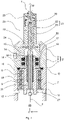
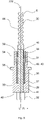
- the 2 shows a schematic view of a further embodiment of a rotor unit 27A for the eccentric screw pump 1.
- FIG 3 12 shows a schematic sectional view of the rotor unit 27A. The following will refer to the 2 and 3 referenced at the same time.
- the rotor assembly 27A includes a drive shaft 28, a rotor 30, and a flexshaft 31 connecting the rotor 30 to the drive shaft 28.
- the drive shaft 28 includes an interface 32 by which the rotor assembly 27A can be coupled to the drive member 29.
- the drive element 29 can transmit a torque to the rotor unit 27A with the aid of the interface 32 .
- Torque is transmitted from the drive shaft 28 to the flexshaft 31 and from the flexshaft 31 to the rotor 30 .
- the drive shaft 28, the flexible shaft 31 and the rotor 30 are connected to one another in a rotationally fixed manner.
- the drive shaft 28 includes a bearing surface 33 on which the bearing elements 8, 9 can be mounted, as well as a sealing surface 34.
- the sealing elements 17 , 18 can rest against the sealing surface 34 in a sealing manner.
- a circumferential step 35 is provided between the bearing surface 33 and the sealing surface 34 viewed in the longitudinal direction L, which extends out both over the bearing surface 33 and over the sealing surface 34 viewed in the radial direction R.
- the drive shaft 28 also includes a recess 36 in which the flex shaft 31 is accommodated.
- the recess 36 has a first end 37 facing away from the rotor 30 and a second end 38 facing the rotor 30 .
- the recess 36 widens from the first end 37 in the direction of the second end 38, so that the recess 36 has a smaller diameter at the first end 37 than at the second end 38.
- the recess 36 can for this purpose, as in FIG 3 shown, be designed as a stepped bore. However, the recess 36 can also have a conical or frustoconical geometry.
- the drive shaft 28 also includes a first end face 39 facing the rotor 30 and a second end face 40 facing away from the rotor 30.
- the drive shaft 28 has an interface 41, with the help of which the flex shaft 31 is connected to the drive shaft 28 in a torque-proof manner.
- the interface 41 can, for example, comprise an adhesive connection, a screw connection, a soldered connection, a welded connection or the like.
- the flexible shaft 31 is preferably designed as a steel cable.
- the flex shaft 31 can also be made of a plastic material.
- a gap 42 running completely around the flex shaft 31 is provided between the flex shaft 31 and the drive shaft 28 .
- the gap 42 can be an air gap be.
- the gap 42, as in FIG 3 shown, also be filled with a sealant 43.
- the sealing compound 43 is elastically deformable, so that it does not impede the radial movement of the flex shaft 31 in the gap 42 or only insignificantly.
- a material with a low Shore hardness can be used for the sealing compound 43 .
- sealing compound 43 can be a silicone, in particular a two-component silicone, a silicone that cures at room temperature or RTV silicone (Room Temperature Vulcanizing Silicone), a silicone that cures at high temperatures, a thermoplastic elastomer (TPE), in particular a thermoplastic Polyurethane (TPU), a thermoplastic vulcanizate (TPV), a fluorovinyl methyl silicone rubber (FVMQ) or the like.
- TPE thermoplastic elastomer
- TPU thermoplastic Polyurethane
- TPV thermoplastic vulcanizate
- FVMQ fluorovinyl methyl silicone rubber
- the sealing compound 43 can also be foamed, for example.
- the sealing compound 43 can have an open-pore or a closed-pore structure.
- the sealing compound 43 can be foam rubber-like.
- the rotor 30 is preferably made of steel, in particular stainless steel. However, the rotor 30 can also be made of a plastic material.
- the rotor 30 includes an outer contour 44, as previously mentioned, which is helical or snail shaped. Facing the drive shaft 28, the rotor 30 includes a circumferential shoulder 45.
- the rotor 30 also includes a receiving section 46, which is sleeve-shaped and accommodates the flex shaft 31 at least in sections. For example, the flexible shaft 31 is glued, soldered or welded to the receiving section 46 .
- the sealing element 47 is provided between shoulder 45 and end face 39 of drive shaft 28 .
- the sealing element 47 can be made of rubber, for example.
- the sealing element 47 can also be made of a thermoplastic elastomer (TPE), in particular a thermoplastic polyurethane (TPU).
- TPE thermoplastic elastomer
- TPU thermoplastic polyurethane
- the sealing element 47 has a conical or frusto-conical geometry.
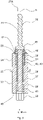
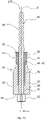
- the 4 shows a schematic view of a further embodiment of a rotor unit 27B for the eccentric screw pump 1.
- FIG figure 5 shows a schematic sectional view of the rotor unit 27B. The following will refer to the 4 and 5 referenced at the same time.
- the rotor unit 27B differs from the rotor unit 27A only in that instead of the cone-shaped or cone-shaped sealing element 47 according to the 2 and 3 a disc-shaped sealing element 47 is provided. Otherwise, the structure of the rotor unit 27B corresponds to the structure of the rotor unit 27A.
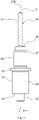
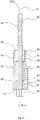
- the 6 shows a schematic view of a further embodiment of a rotor unit 27C for the eccentric screw pump 1.
- the 7 shows a schematic sectional view of the rotor unit 27C. The following will refer to the 6 and 7 referenced at the same time.
- the rotor unit 27C differs from the rotor unit 27A only in that instead of the cone-shaped or cone-shaped sealing element 47 according to FIGS 2 and 3 a bellows-shaped sealing element 47 is provided. Furthermore, the rotor unit 27C does not include any sealing compound 43 accommodated in the gap 42. Optionally, however, the rotor unit 27C can also have the sealing compound 43.
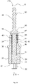
- the 8 shows a schematic sectional view of a further embodiment of a rotor unit 27D.
- the rotor unit 27D differs from the rotor unit 27A only in that instead of the cone-shaped or cone-shaped sealing element 47 according to FIGS 2 and 3 a sealing element 47 in Form of an O-ring is provided. Otherwise, the structure of the rotor unit 27D corresponds to the structure of the rotor unit 27A.
- the 9 shows a schematic sectional view of a further embodiment of a rotor unit 27E.
- the rotor unit 27E differs from the rotor unit 27A only in that the rotor 30 has no circumferential shoulder 45 and that no additional sealing element 47 is provided. Otherwise, the construction of the rotor unit 27C corresponds to that of the rotor unit 27A.
- the 10 shows a schematic sectional view of a further embodiment of a rotor unit 27F.
- the rotor unit 27F differs from the rotor unit 27E only in that the rotor 30 and the flex shaft 31 are not two separately manufactured components which are firmly connected to one another, but form a one-piece component, in particular a one-piece material component.
- the rotor 30 and the flex shaft 31 are designed as a one-piece plastic injection molded component.
- the flex shaft 31 is a flexible rod, in particular a plastic flexible rod.
- the drive shaft 28 can also be designed in one piece, in particular in one piece of material, with the rotor 30 and the flexible shaft 31 .
- the entire rotor unit 27F is a one-piece plastic component, in particular a plastic injection molded component.
- the rotor assembly 27F may be manufactured using a multi-component plastic injection molding process, so that it is possible to manufacture the drive shaft 28, flexshaft 31 and rotor 30 as a one-piece component with different plastic materials.
- the 11 shows a schematic sectional view of a further embodiment of a rotor unit 27G.
- the rotor assembly 27G differs from that Rotor unit 27F only in that the rotor unit 27G has no sealing compound 43. That is, the gap 42 surrounding the flex shaft 31 is an air gap.
- the omission of the sealing compound 43 has the advantage that an additional work step of filling in the sealing compound 43 can be dispensed with.
- the rotor unit 27G can then be produced as a plastic injection-molded component without further post-processing in the form of casting the gap 42 with the sealing compound 43 .
- the 12 shows a schematic sectional view of a further embodiment of a rotor unit 27H.
- the rotor unit 27H differs from the rotor unit 27G only in that a first sealing lip 48 and a second sealing lip 49 are formed on the drive shaft 28, in particular on the sealing surface 34.
- the sealing lips 48, 49 are suitable for sealing radially with respect to the sealing surface 16 of the pump housing part 4.
- the sealing lips 48, 49 are molded onto the drive shaft 28 in a plastic injection molding process.
- the sealing lips 48, 49 can be made of the same material as the drive shaft 28.
- the sealing lips 48, 49 can also be made of a different material than the drive shaft 28.
- a multi-component injection molding process can be used for this purpose, for example.
- the rotor unit 27, 27A, 27B, 27C, 27D, 27E, 27F, 27G, 27H can be a disposable item. However, this is not mandatory. Alternatively, the rotor unit 27, 27A, 27B, 27C, 27D, 27E, 27F, 27G, 27H can also be used several times.
- Disposable process solutions also known as single-use technologies, are used in particular to manufacture biopharmaceutical products.
- Various media M are required for biotechnical processes. These include nutrient solutions, cells, buffers for stabilizing the pH value, as well as acids and bases for adjusting and regulating the pH value during cultivation. All media M used must be sterilized before use. For this purpose, two main processes are used in biotechnology: heat sterilization at at least 121 °C at 1 bar overpressure for at least 20 minutes and sterile filtration. Sterile filtration is the method of choice for media M that contain heat-sensitive components such as vitamins, proteins and peptides.
- the disposable process solutions available are each to be regarded as a self-contained module.
- the basic process engineering operations required for the production and purification of the target product are connected in series.
- the pre-configured single-use systems which consist of hoses, single-use tanks, pump heads and filtration or chromatography modules, are self-contained. Sterile connection technologies, usually hose connections, are therefore required to connect two consecutive process steps.
- thermoplastic hoses can be welded together in a sterile manner or existing connections can be severed and the hose ends can be welded.
- Special rapid transfer systems have been developed for connection through a wall.
- hybrid processes in which single-use systems are combined with conventional stainless steel and glass systems.
- closed systems in which the one-way systems are linked together in the order of the process steps, and station systems, in which the intermediate products are transported to the next process step using mobile containers.
- single use (often also referred to as “disposable”) defines an item that is intended for single use. Usually this consists of a plastic material such as polyamide (PA), polycarbonate (PC), polyethylene (PE), polyethersulfone (PESU), polyoxymethylene (POM), polypropylene (PP), polytetrafluoroethylene (PTFE), polyvinyl chloride (PVC) , cellulose acetate (CA) or ethylene vinyl acetate (EVA), and is discarded after use.
- the rotor unit 27, 27A, 27B, 27C, 27D, 27E, 27F, 27G, 27H can consist of one or more of the be made of the aforementioned materials.
- Single-use technology SUT
- SUS single-use technology
- the eccentric screw pump 1 can be used in particular for additive or generative manufacturing. That is, the progressive cavity pump 1 is a 3D print head or can be referred to as such. 3D printing is a comprehensive term for all manufacturing processes in which material can be applied layer by layer to create three-dimensional objects.
- the layered structure is computer-controlled from one or more liquid or solid materials according to specified dimensions and shapes.
- 3D printing Physical or chemical hardening or melting processes take place during construction.
- Typical materials for 3D printing are plastics, synthetic resins, ceramics and metals.
- carbon and graphite materials have also been developed for 3D printing carbon parts.
- it is a primary forming process no special tools are required for a specific product that have stored the respective geometry of the workpiece, such as casting molds.
- 3D printers are used in industry, model making and research to produce models, samples, prototypes, tools, end products or the like. Furthermore, these are also used for private use. There are also applications in home and entertainment, construction, and art and medicine.
- 3D printing has the advantage that the time-consuming production of molds and mold changes are no longer necessary.
- 3D printing has the advantage that there are no additional processing steps after the primary shaping. In most cases, the process is energetically cheaper, especially if the material is only built up once in the required size and mass.
- post-processing may be necessary depending on the area of application.
- the media M can be, for example, silicones, polyurethanes, ceramic and metal pastes, epoxy resins and acrylates.
- the advantages of the progressing cavity pump 1 over other technologies capable of printing liquids are its applicability for high viscosities, the high precision and process stability, the large range of materials that can be used and the high application speed.
- Other technologies are dependent on material adjustments, some of which are strong, in order to achieve a meaningful printing process.
- light-based technologies for liquids always depend on the presence of a photon crosslinker, whereas the progressing cavity pump 1 can print completely independently of the curing mechanism.
- the eccentric screw pump 1 can be used for so-called “bioprinting”.
- bioprinting The field of application of bioprinting is still very young and represents the latest step in cell culture technology. It can be seen as a special form of additive manufacturing at the interface between medical technology and biotechnology.
- the topic of bioprinting is often introduced with words about the great need for donor organs. It is essential that tissue and organs are artificially produced in the future in order to meet the enormous demand. Realistically, this vision is still a long way off if it should ever become reality.
- mini-organs are printed, which depict all the essential functions of a real organ be able. Using microfluidic techniques, these mini-organs can be combined into multi-organ systems and the systemic effects of active substances can thus be tested without the need for animal experiments.
- cell-loaded gels or matrices are produced for maintaining and cultivating the same with the aid of the eccentric screw pump 1, in particular with the aid of a bioprinter.
- This is done through a layered structure, which is known from additive manufacturing. Since most media M are loaded with living cells during bioprinting, which can only be produced with considerable expenditure of time and money, careful application is essential.
- the stress on the deployed cells increases with the cell density and the viscosity of the medium M. For meaningful constructs, however, the highest possible cell density and stability are required. This creates a tension between cell concentration and application technology.
- the materials for the eccentric screw pump 1 are chosen so that they are as light as possible.
- the housing 2 can be partially made of metal or plastic. Since the components rotor unit 27, 27A, 27B, 27C, 27D, 27E, 27F, 27G, 27H and stator 21 can be made of a plastic material, the weight is further reduced. Due to the reduced installation space of the rotor unit 27, 27A, 27B, 27C, 27D, 27E, 27F, 27G, 27H along the longitudinal direction L, a weight reduction can also be achieved.
- eccentric screw pump 1 in the field of bioprinting
- other areas of application are also conceivable.
- the use of the progressing cavity pump 1 does not have to be limited to bioprinting.
- the printing of materials such as silicones, epoxy resins, polyurethanes, Ceramic, metal and solder pastes are also possible. With a compact design, it is also conceivable to open up the market for amateur 3D printers.
- a rotor unit 27, 27A, 27B, 27C, 27D, 27E, 27F, 27G, 27H designed as a disposable article, which can be quickly replaced in the event of a malfunction without major damage, is therefore advantageous.
- the eccentric screw pump 1 can be used for the precise application of the medium M in wound care, in the body, in operations, in dental treatments or for the delivery of medication.
- An example of an interface between additive manufacturing and medical technology is the printing of tablets. Problems with interactions, overdosing and underdosing as well as forgetting to take a tablet can be counteracted by individually creating tablets with patient-specific active ingredients and active ingredient contents.
- the eccentric screw pump 1 can also be used for printing tablets.
- the eccentric screw pump 1 can also be used for micro dosing in the production of film tablets, for dosing vaccines, active ingredients, particularly expensive active ingredients, or for plaster application by dosing.
- the progressing cavity pump 1 can also be used for micro dosing in aseptic applications.
- the progressing cavity pump can also be used for the production of very small components, for example for gluing endoscopes 1 find application.
- the eccentric screw pump 1 can be used for dispensing expensive active ingredients, either in a continuous or discontinuous process. It is also possible to produce personalized tablets, especially film-coated tablets. It is also possible to use several active ingredients in one tablet, in particular a film tablet, or on active plasters.
- the eccentric screw pump 1 can also be used in cosmetics, in particular in personalized cosmetics, for dosing very small quantities.
- the eccentric screw pump 1 can be mains operated or battery operated. This means that battery operation of the eccentric screw pump 1 is possible. As a result, the eccentric screw pump 1 is independent of a power grid.
- the eccentric screw pump 1 can thus work independently as a handheld device.
- the eccentric screw pump 1 can be used to meter soldering paste at a manual workstation.
- the eccentric screw pump 1 can thus be used in the manner of a pipetting device or pipetting aid, with the difference that the eccentric screw pump 1 can also be used to dose highly viscous media M.
- such a self-sufficient eccentric screw pump 1 can also be used to treat quick wounds, for example for field treatment by emergency services, in doctors' surgeries or in the operating room.
- the media M that can be dosed are, for example, waxes, in particular bone waxes, adhesives, medicaments, denture materials, artificial skin or the like.
Landscapes
- Engineering & Computer Science (AREA)
- Mechanical Engineering (AREA)
- General Engineering & Computer Science (AREA)
- Rotary Pumps (AREA)
Priority Applications (4)
| Application Number | Priority Date | Filing Date | Title |
|---|---|---|---|
| EP20211922.8A EP4008903B1 (fr) | 2020-12-04 | 2020-12-04 | Unité de rotor et pompe à vis excentrique |
| PCT/EP2021/081274 WO2022117300A1 (fr) | 2020-12-04 | 2021-11-10 | Unité de rotor et pompe à vis excentrée |
| US18/039,932 US12018687B2 (en) | 2020-12-04 | 2021-11-10 | Rotor unit and eccentric screw pump |
| CN202180091455.7A CN116806290A (zh) | 2020-12-04 | 2021-11-10 | 转子单元和单螺杆泵 |
Applications Claiming Priority (1)
| Application Number | Priority Date | Filing Date | Title |
|---|---|---|---|
| EP20211922.8A EP4008903B1 (fr) | 2020-12-04 | 2020-12-04 | Unité de rotor et pompe à vis excentrique |
Publications (2)
| Publication Number | Publication Date |
|---|---|
| EP4008903A1 true EP4008903A1 (fr) | 2022-06-08 |
| EP4008903B1 EP4008903B1 (fr) | 2023-01-25 |
Family
ID=73726679
Family Applications (1)
| Application Number | Title | Priority Date | Filing Date |
|---|---|---|---|
| EP20211922.8A Active EP4008903B1 (fr) | 2020-12-04 | 2020-12-04 | Unité de rotor et pompe à vis excentrique |
Country Status (4)
| Country | Link |
|---|---|
| US (1) | US12018687B2 (fr) |
| EP (1) | EP4008903B1 (fr) |
| CN (1) | CN116806290A (fr) |
| WO (1) | WO2022117300A1 (fr) |
Cited By (1)
| Publication number | Priority date | Publication date | Assignee | Title |
|---|---|---|---|---|
| WO2024083464A1 (fr) * | 2022-10-18 | 2024-04-25 | Visec (Asia) Technology Pte Ltd. | Procédé et moule de moulage par injection destinés à la fabrication d'une unité rotor pour une pompe à cavité progressive ainsi qu'unité rotor, unité stator et pompe à cavité progressive |
Families Citing this family (3)
| Publication number | Priority date | Publication date | Assignee | Title |
|---|---|---|---|---|
| DE202018104142U1 (de) * | 2018-07-18 | 2019-10-22 | Vogelsang Gmbh & Co. Kg | Rotor für eine Exzenterschneckenpumpe |
| EP4474650B1 (fr) | 2023-06-09 | 2026-03-25 | Illinois Tool Works Inc. | Pompe à vis et ses composants |
| US12533995B2 (en) | 2023-08-31 | 2026-01-27 | Illinois Tool Works Inc. | Battery electric vehicle temperature-regulation system |
Citations (5)
| Publication number | Priority date | Publication date | Assignee | Title |
|---|---|---|---|---|
| US2545626A (en) * | 1946-12-17 | 1951-03-20 | Robbins & Myers | Spiral gear pump and allied device |
| US2545604A (en) * | 1946-02-01 | 1951-03-20 | Robbins & Myers | Pump |
| JPS551422A (en) * | 1978-06-20 | 1980-01-08 | Kojiro Hamada | Monolithic screw pump |
| DE202007018923U1 (de) | 2007-08-06 | 2009-10-15 | Visco Tec Pumpen- Und Dosiertechnik Gmbh | Dosiervorrichtung zum Dosieren eines Fluids |
| EP2416014A1 (fr) * | 2009-03-31 | 2012-02-08 | Heishin Ltd. | Mécanisme d'entraînement de rotor et dispositif de pompe équipé dudit mécanisme |
Family Cites Families (5)
| Publication number | Priority date | Publication date | Assignee | Title |
|---|---|---|---|---|
| US5769618A (en) * | 1995-09-25 | 1998-06-23 | Heishin Sobi Kabushiki Kaisha | Uniaxial eccentric screw pump having a flexible plastic shaft |
| DE20110292U1 (de) * | 2001-06-21 | 2002-10-24 | Kühn Umweltprodukte GmbH, 29683 Fallingbostel | Vorrichtung zum Eindicken oder Entwässern von Schlämmen, Sedimenten aus Gewässern o.dgl., insbesondere von Überschußschlämmen in Kläranlagen |
| EP1308624B1 (fr) * | 2001-10-30 | 2005-12-07 | Grundfos a/s | Pompe à moteur submersible |
| JP5070515B2 (ja) * | 2007-03-08 | 2012-11-14 | 兵神装備株式会社 | ロータ駆動機構及びポンプ装置 |
| CN106246534B (zh) * | 2016-09-09 | 2018-01-12 | 中国石油大学(华东) | 一种分层注水用水力驱动螺杆泵装置 |
-
2020
- 2020-12-04 EP EP20211922.8A patent/EP4008903B1/fr active Active
-
2021
- 2021-11-10 CN CN202180091455.7A patent/CN116806290A/zh active Pending
- 2021-11-10 US US18/039,932 patent/US12018687B2/en active Active
- 2021-11-10 WO PCT/EP2021/081274 patent/WO2022117300A1/fr not_active Ceased
Patent Citations (5)
| Publication number | Priority date | Publication date | Assignee | Title |
|---|---|---|---|---|
| US2545604A (en) * | 1946-02-01 | 1951-03-20 | Robbins & Myers | Pump |
| US2545626A (en) * | 1946-12-17 | 1951-03-20 | Robbins & Myers | Spiral gear pump and allied device |
| JPS551422A (en) * | 1978-06-20 | 1980-01-08 | Kojiro Hamada | Monolithic screw pump |
| DE202007018923U1 (de) | 2007-08-06 | 2009-10-15 | Visco Tec Pumpen- Und Dosiertechnik Gmbh | Dosiervorrichtung zum Dosieren eines Fluids |
| EP2416014A1 (fr) * | 2009-03-31 | 2012-02-08 | Heishin Ltd. | Mécanisme d'entraînement de rotor et dispositif de pompe équipé dudit mécanisme |
Cited By (1)
| Publication number | Priority date | Publication date | Assignee | Title |
|---|---|---|---|---|
| WO2024083464A1 (fr) * | 2022-10-18 | 2024-04-25 | Visec (Asia) Technology Pte Ltd. | Procédé et moule de moulage par injection destinés à la fabrication d'une unité rotor pour une pompe à cavité progressive ainsi qu'unité rotor, unité stator et pompe à cavité progressive |
Also Published As
| Publication number | Publication date |
|---|---|
| US20230417241A1 (en) | 2023-12-28 |
| EP4008903B1 (fr) | 2023-01-25 |
| WO2022117300A1 (fr) | 2022-06-09 |
| CN116806290A (zh) | 2023-09-26 |
| US12018687B2 (en) | 2024-06-25 |
Similar Documents
| Publication | Publication Date | Title |
|---|---|---|
| EP4008903B1 (fr) | Unité de rotor et pompe à vis excentrique | |
| DE69829669T2 (de) | Pumpsystem | |
| DE102010045935B4 (de) | Behälter, Behältersystem, Verfahren zum Applizieren einer pastösen Masse aus diesem Behälter sowie Verfahren zum Mischen mehrerer Massen aus diesem Behälter | |
| EP3685791B1 (fr) | Cartouches à une voie pour le stockage et l'extraction de masses de formage dentaires à deux composants | |
| DE60021633T2 (de) | Hilfswerkzeug zum Auspressen eines chemischen Wirkstoffes, Kneter zum Vorbereiten und Auspressen eines chemischen Wirkstoffes, und Verfahren zur Verwendung derselben | |
| DE112010003746B4 (de) | Komprimierbarer Rotor für eine Fluidpumpe | |
| DE60126740T2 (de) | Verabreichungssystem für scherempfindliche arzneistoffe | |
| DE60223074T2 (de) | Vorrichtung zur extrusion von dünnwandigen rohren | |
| EP1274501B1 (fr) | Melangeur | |
| EP2987551B1 (fr) | Dispositif de sortie dote d'un melangeur entraine elastiquement et procédé | |
| EP3865709B1 (fr) | Dispositif de pompe, dispositif jetable et procédé de fonctionnement d'un dispositif de pompe | |
| DE102005024363B4 (de) | Vorrichtung und Verfahren zur Förderung von Flüssigkeiten | |
| WO2010139078A1 (fr) | Dispositif mélangeur pour la production d'un mélange d'au moins trois composants | |
| WO2001070146A2 (fr) | Dispositif de preparation et d'application de materiaux d'implant | |
| DE202020005671U1 (de) | Rotoreinheit und Exzenterschneckenpumpe | |
| EP3921013B1 (fr) | Connecteur sterile pour le transfer d'un medium liquide | |
| EP4257232A1 (fr) | Dispositif et procédé de préparation de la pâte de ciment osseux | |
| WO2022083913A1 (fr) | Système de cartouche et pompe à vis excentrique | |
| CN105854685B (zh) | 一种动态细胞打印微混合器 | |
| EP4101520A1 (fr) | Dispositif et procédé de filtration à flux tangentiel d'un fluide | |
| DE10333384B4 (de) | Mischanordnung zum Herstellen flüssiger oder halbfester Produkte | |
| WO2024052275A1 (fr) | Procédé de mélange dynamique en ligne | |
| EP4382197A2 (fr) | Système de mélange et procédé de mélange d'un fluide primaire avec une substance secondaire fluide | |
| EP3234362B1 (fr) | Dispositif de transport | |
| DE102023122236B4 (de) | Exzenterschneckenpumpe, Dosieranlage und Verfahren |
Legal Events
| Date | Code | Title | Description |
|---|---|---|---|
| STAA | Information on the status of an ep patent application or granted ep patent |
Free format text: STATUS: EXAMINATION IS IN PROGRESS |
|
| PUAI | Public reference made under article 153(3) epc to a published international application that has entered the european phase |
Free format text: ORIGINAL CODE: 0009012 |
|
| 17P | Request for examination filed |
Effective date: 20211117 |
|
| AK | Designated contracting states |
Kind code of ref document: A1 Designated state(s): AL AT BE BG CH CY CZ DE DK EE ES FI FR GB GR HR HU IE IS IT LI LT LU LV MC MK MT NL NO PL PT RO RS SE SI SK SM TR |
|
| GRAP | Despatch of communication of intention to grant a patent |
Free format text: ORIGINAL CODE: EPIDOSNIGR1 |
|
| STAA | Information on the status of an ep patent application or granted ep patent |
Free format text: STATUS: GRANT OF PATENT IS INTENDED |
|
| RIN1 | Information on inventor provided before grant (corrected) |
Inventor name: AUER, JUERGEN Inventor name: KELSCH, HORST |
|
| INTG | Intention to grant announced |
Effective date: 20220721 |
|
| RIN1 | Information on inventor provided before grant (corrected) |
Inventor name: AUER, JUERGEN Inventor name: KELSCH, HORST |
|
| GRAS | Grant fee paid |
Free format text: ORIGINAL CODE: EPIDOSNIGR3 |
|
| GRAA | (expected) grant |
Free format text: ORIGINAL CODE: 0009210 |
|
| STAA | Information on the status of an ep patent application or granted ep patent |
Free format text: STATUS: THE PATENT HAS BEEN GRANTED |
|
| AK | Designated contracting states |
Kind code of ref document: B1 Designated state(s): AL AT BE BG CH CY CZ DE DK EE ES FI FR GB GR HR HU IE IS IT LI LT LU LV MC MK MT NL NO PL PT RO RS SE SI SK SM TR |
|
| REG | Reference to a national code |
Ref country code: GB Ref legal event code: FG4D Free format text: NOT ENGLISH |
|
| REG | Reference to a national code |
Ref country code: CH Ref legal event code: EP |
|
| REG | Reference to a national code |
Ref country code: NL Ref legal event code: FP Ref country code: AT Ref legal event code: REF Ref document number: 1546087 Country of ref document: AT Kind code of ref document: T Effective date: 20230215 Ref country code: IE Ref legal event code: FG4D Free format text: LANGUAGE OF EP DOCUMENT: GERMAN |
|
| REG | Reference to a national code |
Ref country code: DE Ref legal event code: R096 Ref document number: 502020002441 Country of ref document: DE |
|
| REG | Reference to a national code |
Ref country code: SE Ref legal event code: TRGR |
|
| REG | Reference to a national code |
Ref country code: LT Ref legal event code: MG9D |
|
| PG25 | Lapsed in a contracting state [announced via postgrant information from national office to epo] |
Ref country code: RS Free format text: LAPSE BECAUSE OF FAILURE TO SUBMIT A TRANSLATION OF THE DESCRIPTION OR TO PAY THE FEE WITHIN THE PRESCRIBED TIME-LIMIT Effective date: 20230125 Ref country code: PT Free format text: LAPSE BECAUSE OF FAILURE TO SUBMIT A TRANSLATION OF THE DESCRIPTION OR TO PAY THE FEE WITHIN THE PRESCRIBED TIME-LIMIT Effective date: 20230525 Ref country code: NO Free format text: LAPSE BECAUSE OF FAILURE TO SUBMIT A TRANSLATION OF THE DESCRIPTION OR TO PAY THE FEE WITHIN THE PRESCRIBED TIME-LIMIT Effective date: 20230425 Ref country code: LV Free format text: LAPSE BECAUSE OF FAILURE TO SUBMIT A TRANSLATION OF THE DESCRIPTION OR TO PAY THE FEE WITHIN THE PRESCRIBED TIME-LIMIT Effective date: 20230125 Ref country code: LT Free format text: LAPSE BECAUSE OF FAILURE TO SUBMIT A TRANSLATION OF THE DESCRIPTION OR TO PAY THE FEE WITHIN THE PRESCRIBED TIME-LIMIT Effective date: 20230125 Ref country code: HR Free format text: LAPSE BECAUSE OF FAILURE TO SUBMIT A TRANSLATION OF THE DESCRIPTION OR TO PAY THE FEE WITHIN THE PRESCRIBED TIME-LIMIT Effective date: 20230125 Ref country code: ES Free format text: LAPSE BECAUSE OF FAILURE TO SUBMIT A TRANSLATION OF THE DESCRIPTION OR TO PAY THE FEE WITHIN THE PRESCRIBED TIME-LIMIT Effective date: 20230125 |
|
| PG25 | Lapsed in a contracting state [announced via postgrant information from national office to epo] |
Ref country code: PL Free format text: LAPSE BECAUSE OF FAILURE TO SUBMIT A TRANSLATION OF THE DESCRIPTION OR TO PAY THE FEE WITHIN THE PRESCRIBED TIME-LIMIT Effective date: 20230125 Ref country code: IS Free format text: LAPSE BECAUSE OF FAILURE TO SUBMIT A TRANSLATION OF THE DESCRIPTION OR TO PAY THE FEE WITHIN THE PRESCRIBED TIME-LIMIT Effective date: 20230525 Ref country code: GR Free format text: LAPSE BECAUSE OF FAILURE TO SUBMIT A TRANSLATION OF THE DESCRIPTION OR TO PAY THE FEE WITHIN THE PRESCRIBED TIME-LIMIT Effective date: 20230426 Ref country code: FI Free format text: LAPSE BECAUSE OF FAILURE TO SUBMIT A TRANSLATION OF THE DESCRIPTION OR TO PAY THE FEE WITHIN THE PRESCRIBED TIME-LIMIT Effective date: 20230125 |
|
| REG | Reference to a national code |
Ref country code: DE Ref legal event code: R097 Ref document number: 502020002441 Country of ref document: DE |
|
| PG25 | Lapsed in a contracting state [announced via postgrant information from national office to epo] |
Ref country code: SM Free format text: LAPSE BECAUSE OF FAILURE TO SUBMIT A TRANSLATION OF THE DESCRIPTION OR TO PAY THE FEE WITHIN THE PRESCRIBED TIME-LIMIT Effective date: 20230125 Ref country code: RO Free format text: LAPSE BECAUSE OF FAILURE TO SUBMIT A TRANSLATION OF THE DESCRIPTION OR TO PAY THE FEE WITHIN THE PRESCRIBED TIME-LIMIT Effective date: 20230125 Ref country code: EE Free format text: LAPSE BECAUSE OF FAILURE TO SUBMIT A TRANSLATION OF THE DESCRIPTION OR TO PAY THE FEE WITHIN THE PRESCRIBED TIME-LIMIT Effective date: 20230125 Ref country code: DK Free format text: LAPSE BECAUSE OF FAILURE TO SUBMIT A TRANSLATION OF THE DESCRIPTION OR TO PAY THE FEE WITHIN THE PRESCRIBED TIME-LIMIT Effective date: 20230125 Ref country code: CZ Free format text: LAPSE BECAUSE OF FAILURE TO SUBMIT A TRANSLATION OF THE DESCRIPTION OR TO PAY THE FEE WITHIN THE PRESCRIBED TIME-LIMIT Effective date: 20230125 |
|
| PG25 | Lapsed in a contracting state [announced via postgrant information from national office to epo] |
Ref country code: SK Free format text: LAPSE BECAUSE OF FAILURE TO SUBMIT A TRANSLATION OF THE DESCRIPTION OR TO PAY THE FEE WITHIN THE PRESCRIBED TIME-LIMIT Effective date: 20230125 |
|
| PLBE | No opposition filed within time limit |
Free format text: ORIGINAL CODE: 0009261 |
|
| STAA | Information on the status of an ep patent application or granted ep patent |
Free format text: STATUS: NO OPPOSITION FILED WITHIN TIME LIMIT |
|
| 26N | No opposition filed |
Effective date: 20231026 |
|
| PG25 | Lapsed in a contracting state [announced via postgrant information from national office to epo] |
Ref country code: SI Free format text: LAPSE BECAUSE OF FAILURE TO SUBMIT A TRANSLATION OF THE DESCRIPTION OR TO PAY THE FEE WITHIN THE PRESCRIBED TIME-LIMIT Effective date: 20230125 |
|
| PG25 | Lapsed in a contracting state [announced via postgrant information from national office to epo] |
Ref country code: LU Free format text: LAPSE BECAUSE OF NON-PAYMENT OF DUE FEES Effective date: 20231204 |
|
| PG25 | Lapsed in a contracting state [announced via postgrant information from national office to epo] |
Ref country code: MC Free format text: LAPSE BECAUSE OF FAILURE TO SUBMIT A TRANSLATION OF THE DESCRIPTION OR TO PAY THE FEE WITHIN THE PRESCRIBED TIME-LIMIT Effective date: 20230125 |
|
| REG | Reference to a national code |
Ref country code: BE Ref legal event code: MM Effective date: 20231231 |
|
| PG25 | Lapsed in a contracting state [announced via postgrant information from national office to epo] |
Ref country code: MC Free format text: LAPSE BECAUSE OF FAILURE TO SUBMIT A TRANSLATION OF THE DESCRIPTION OR TO PAY THE FEE WITHIN THE PRESCRIBED TIME-LIMIT Effective date: 20230125 Ref country code: LU Free format text: LAPSE BECAUSE OF NON-PAYMENT OF DUE FEES Effective date: 20231204 |
|
| REG | Reference to a national code |
Ref country code: IE Ref legal event code: MM4A |
|
| PG25 | Lapsed in a contracting state [announced via postgrant information from national office to epo] |
Ref country code: IE Free format text: LAPSE BECAUSE OF NON-PAYMENT OF DUE FEES Effective date: 20231204 |
|
| PG25 | Lapsed in a contracting state [announced via postgrant information from national office to epo] |
Ref country code: BE Free format text: LAPSE BECAUSE OF NON-PAYMENT OF DUE FEES Effective date: 20231231 |
|
| PG25 | Lapsed in a contracting state [announced via postgrant information from national office to epo] |
Ref country code: IE Free format text: LAPSE BECAUSE OF NON-PAYMENT OF DUE FEES Effective date: 20231204 Ref country code: BE Free format text: LAPSE BECAUSE OF NON-PAYMENT OF DUE FEES Effective date: 20231231 |
|
| PG25 | Lapsed in a contracting state [announced via postgrant information from national office to epo] |
Ref country code: BG Free format text: LAPSE BECAUSE OF FAILURE TO SUBMIT A TRANSLATION OF THE DESCRIPTION OR TO PAY THE FEE WITHIN THE PRESCRIBED TIME-LIMIT Effective date: 20230125 |
|
| PG25 | Lapsed in a contracting state [announced via postgrant information from national office to epo] |
Ref country code: BG Free format text: LAPSE BECAUSE OF FAILURE TO SUBMIT A TRANSLATION OF THE DESCRIPTION OR TO PAY THE FEE WITHIN THE PRESCRIBED TIME-LIMIT Effective date: 20230125 |
|
| PG25 | Lapsed in a contracting state [announced via postgrant information from national office to epo] |
Ref country code: CY Free format text: LAPSE BECAUSE OF FAILURE TO SUBMIT A TRANSLATION OF THE DESCRIPTION OR TO PAY THE FEE WITHIN THE PRESCRIBED TIME-LIMIT; INVALID AB INITIO Effective date: 20201204 |
|
| PG25 | Lapsed in a contracting state [announced via postgrant information from national office to epo] |
Ref country code: HU Free format text: LAPSE BECAUSE OF FAILURE TO SUBMIT A TRANSLATION OF THE DESCRIPTION OR TO PAY THE FEE WITHIN THE PRESCRIBED TIME-LIMIT; INVALID AB INITIO Effective date: 20201204 |
|
| PG25 | Lapsed in a contracting state [announced via postgrant information from national office to epo] |
Ref country code: TR Free format text: LAPSE BECAUSE OF FAILURE TO SUBMIT A TRANSLATION OF THE DESCRIPTION OR TO PAY THE FEE WITHIN THE PRESCRIBED TIME-LIMIT Effective date: 20230125 |
|
| REG | Reference to a national code |
Ref country code: CH Ref legal event code: U11 Free format text: ST27 STATUS EVENT CODE: U-0-0-U10-U11 (AS PROVIDED BY THE NATIONAL OFFICE) Effective date: 20260101 |
|
| PGFP | Annual fee paid to national office [announced via postgrant information from national office to epo] |
Ref country code: DE Payment date: 20251215 Year of fee payment: 6 |
|
| PGFP | Annual fee paid to national office [announced via postgrant information from national office to epo] |
Ref country code: GB Payment date: 20251218 Year of fee payment: 6 |
|
| PGFP | Annual fee paid to national office [announced via postgrant information from national office to epo] |
Ref country code: AT Payment date: 20260113 Year of fee payment: 5 |
|
| PGFP | Annual fee paid to national office [announced via postgrant information from national office to epo] |
Ref country code: NL Payment date: 20251217 Year of fee payment: 6 Ref country code: FR Payment date: 20251218 Year of fee payment: 6 |
|
| PGFP | Annual fee paid to national office [announced via postgrant information from national office to epo] |
Ref country code: SE Payment date: 20251217 Year of fee payment: 6 |
|
| PGFP | Annual fee paid to national office [announced via postgrant information from national office to epo] |
Ref country code: IT Payment date: 20251231 Year of fee payment: 6 |
|
| PGFP | Annual fee paid to national office [announced via postgrant information from national office to epo] |
Ref country code: CH Payment date: 20260101 Year of fee payment: 6 |