EP4008903A1 - Rotoreinheit und exzenterschneckenpumpe - Google Patents
Rotoreinheit und exzenterschneckenpumpe Download PDFInfo
- Publication number
- EP4008903A1 EP4008903A1 EP20211922.8A EP20211922A EP4008903A1 EP 4008903 A1 EP4008903 A1 EP 4008903A1 EP 20211922 A EP20211922 A EP 20211922A EP 4008903 A1 EP4008903 A1 EP 4008903A1
- Authority
- EP
- European Patent Office
- Prior art keywords
- rotor
- drive shaft
- shaft
- rotor unit
- eccentric screw
- Prior art date
- Legal status (The legal status is an assumption and is not a legal conclusion. Google has not performed a legal analysis and makes no representation as to the accuracy of the status listed.)
- Granted
Links
Images


Classifications
-
- F—MECHANICAL ENGINEERING; LIGHTING; HEATING; WEAPONS; BLASTING
- F04—POSITIVE - DISPLACEMENT MACHINES FOR LIQUIDS; PUMPS FOR LIQUIDS OR ELASTIC FLUIDS
- F04C—ROTARY-PISTON, OR OSCILLATING-PISTON, POSITIVE-DISPLACEMENT MACHINES FOR LIQUIDS; ROTARY-PISTON, OR OSCILLATING-PISTON, POSITIVE-DISPLACEMENT PUMPS
- F04C2/00—Rotary-piston machines or pumps
- F04C2/08—Rotary-piston machines or pumps of intermeshing-engagement type, i.e. with engagement of co-operating members similar to that of toothed gearing
- F04C2/10—Rotary-piston machines or pumps of intermeshing-engagement type, i.e. with engagement of co-operating members similar to that of toothed gearing of internal-axis type with the outer member having more teeth or tooth-equivalents, e.g. rollers, than the inner member
- F04C2/107—Rotary-piston machines or pumps of intermeshing-engagement type, i.e. with engagement of co-operating members similar to that of toothed gearing of internal-axis type with the outer member having more teeth or tooth-equivalents, e.g. rollers, than the inner member with helical teeth
- F04C2/1071—Rotary-piston machines or pumps of intermeshing-engagement type, i.e. with engagement of co-operating members similar to that of toothed gearing of internal-axis type with the outer member having more teeth or tooth-equivalents, e.g. rollers, than the inner member with helical teeth the inner and outer member having a different number of threads and one of the two being made of elastic materials, e.g. Moineau type
- F04C2/1073—Rotary-piston machines or pumps of intermeshing-engagement type, i.e. with engagement of co-operating members similar to that of toothed gearing of internal-axis type with the outer member having more teeth or tooth-equivalents, e.g. rollers, than the inner member with helical teeth the inner and outer member having a different number of threads and one of the two being made of elastic materials, e.g. Moineau type where one member is stationary while the other member rotates and orbits
-
- F—MECHANICAL ENGINEERING; LIGHTING; HEATING; WEAPONS; BLASTING
- F04—POSITIVE - DISPLACEMENT MACHINES FOR LIQUIDS; PUMPS FOR LIQUIDS OR ELASTIC FLUIDS
- F04C—ROTARY-PISTON, OR OSCILLATING-PISTON, POSITIVE-DISPLACEMENT MACHINES FOR LIQUIDS; ROTARY-PISTON, OR OSCILLATING-PISTON, POSITIVE-DISPLACEMENT PUMPS
- F04C15/00—Component parts, details or accessories of machines, pumps or pumping installations, not provided for in groups F04C2/00 - F04C14/00
- F04C15/0003—Sealing arrangements in rotary-piston machines or pumps
-
- F—MECHANICAL ENGINEERING; LIGHTING; HEATING; WEAPONS; BLASTING
- F04—POSITIVE - DISPLACEMENT MACHINES FOR LIQUIDS; PUMPS FOR LIQUIDS OR ELASTIC FLUIDS
- F04C—ROTARY-PISTON, OR OSCILLATING-PISTON, POSITIVE-DISPLACEMENT MACHINES FOR LIQUIDS; ROTARY-PISTON, OR OSCILLATING-PISTON, POSITIVE-DISPLACEMENT PUMPS
- F04C15/00—Component parts, details or accessories of machines, pumps or pumping installations, not provided for in groups F04C2/00 - F04C14/00
- F04C15/0057—Driving elements, brakes, couplings, transmission specially adapted for machines or pumps
- F04C15/0061—Means for transmitting movement from the prime mover to driven parts of the pump, e.g. clutches, couplings, transmissions
- F04C15/0065—Means for transmitting movement from the prime mover to driven parts of the pump, e.g. clutches, couplings, transmissions for eccentric movement
-
- F—MECHANICAL ENGINEERING; LIGHTING; HEATING; WEAPONS; BLASTING
- F04—POSITIVE - DISPLACEMENT MACHINES FOR LIQUIDS; PUMPS FOR LIQUIDS OR ELASTIC FLUIDS
- F04C—ROTARY-PISTON, OR OSCILLATING-PISTON, POSITIVE-DISPLACEMENT MACHINES FOR LIQUIDS; ROTARY-PISTON, OR OSCILLATING-PISTON, POSITIVE-DISPLACEMENT PUMPS
- F04C15/00—Component parts, details or accessories of machines, pumps or pumping installations, not provided for in groups F04C2/00 - F04C14/00
- F04C15/0057—Driving elements, brakes, couplings, transmission specially adapted for machines or pumps
- F04C15/0061—Means for transmitting movement from the prime mover to driven parts of the pump, e.g. clutches, couplings, transmissions
- F04C15/0073—Couplings between rotors and input or output shafts acting by interengaging or mating parts, i.e. positive coupling of rotor and shaft
-
- F—MECHANICAL ENGINEERING; LIGHTING; HEATING; WEAPONS; BLASTING
- F04—POSITIVE - DISPLACEMENT MACHINES FOR LIQUIDS; PUMPS FOR LIQUIDS OR ELASTIC FLUIDS
- F04C—ROTARY-PISTON, OR OSCILLATING-PISTON, POSITIVE-DISPLACEMENT MACHINES FOR LIQUIDS; ROTARY-PISTON, OR OSCILLATING-PISTON, POSITIVE-DISPLACEMENT PUMPS
- F04C2/00—Rotary-piston machines or pumps
- F04C2/08—Rotary-piston machines or pumps of intermeshing-engagement type, i.e. with engagement of co-operating members similar to that of toothed gearing
- F04C2/10—Rotary-piston machines or pumps of intermeshing-engagement type, i.e. with engagement of co-operating members similar to that of toothed gearing of internal-axis type with the outer member having more teeth or tooth-equivalents, e.g. rollers, than the inner member
- F04C2/107—Rotary-piston machines or pumps of intermeshing-engagement type, i.e. with engagement of co-operating members similar to that of toothed gearing of internal-axis type with the outer member having more teeth or tooth-equivalents, e.g. rollers, than the inner member with helical teeth
- F04C2/1071—Rotary-piston machines or pumps of intermeshing-engagement type, i.e. with engagement of co-operating members similar to that of toothed gearing of internal-axis type with the outer member having more teeth or tooth-equivalents, e.g. rollers, than the inner member with helical teeth the inner and outer member having a different number of threads and one of the two being made of elastic materials, e.g. Moineau type
-
- F—MECHANICAL ENGINEERING; LIGHTING; HEATING; WEAPONS; BLASTING
- F04—POSITIVE - DISPLACEMENT MACHINES FOR LIQUIDS; PUMPS FOR LIQUIDS OR ELASTIC FLUIDS
- F04C—ROTARY-PISTON, OR OSCILLATING-PISTON, POSITIVE-DISPLACEMENT MACHINES FOR LIQUIDS; ROTARY-PISTON, OR OSCILLATING-PISTON, POSITIVE-DISPLACEMENT PUMPS
- F04C2240/00—Components
- F04C2240/60—Shafts
- F04C2240/601—Shaft flexion
Definitions
- the present invention relates to a rotor unit for an eccentric screw pump and an eccentric screw pump, in particular a 3D print head, with such a rotor unit.
- Eccentric screw pumps include a stator and a rotor rotatably accommodated in the stator.
- a medium to be metered is conveyed by the interaction of the rotor with the stator in a longitudinal direction of the eccentric screw pump away from a drive element of the eccentric screw pump according to the endless piston principle.
- the delivery volume per unit of time depends on the speed, size, pitch and geometry of the rotor.
- the rotor During operation of such an eccentric screw pump, the rotor performs an eccentric movement in the stator. In order to enable this eccentric movement, the rotor is connected to a drive shaft via a flexibly deformable shaft or a joint. This results in a relatively large installation space viewed in the longitudinal direction of the eccentric screw pump. This space requires a large dead volume in a pump housing of the eccentric screw pump. In the case of expensive media in particular, it is desirable for this dead space volume to be as small as possible.
- the DE 20 2007 018 923 U1 describes an eccentric screw pump as mentioned above, which has a rotor unit with a drive shaft, a rotor and a flexible shaft arranged between the drive shaft and the rotor.
- the rotor unit comprises a drive shaft, which can be driven using a drive element of the eccentric screw pump, a worm-shaped rotor and a flex shaft, which connects the drive shaft to the rotor, the flex shaft being accommodated at least in sections within the drive shaft, and being between the flex shaft and the drive shaft a gap surrounding the flex shaft is provided, which allows radial movement of the flex shaft within the drive shaft.
- the flexible shaft is accommodated at least in sections within the drive shaft, a reduced installation space can be achieved along a longitudinal direction of the rotor unit, which is oriented from the drive shaft in the direction of the rotor. This makes it possible to constructively design the eccentric screw pump in such a way that it has a minimal dead volume. This is particularly advantageous when dosing expensive media.
- the rotor unit can also be referred to as a rotor train, in particular as a compact rotor train.
- the terms “rotor unit”, “rotor train” and “compact rotor train” can be interchanged at will.
- the rotor unit is preferably part of the progressing cavity pump.
- the rotor unit is exchangeable.
- the drive shaft is rotatably mounted about an axis of symmetry of the rotor unit, in particular in a bearing housing part of the eccentric screw pump.
- bearing elements can be provided in the form of roller bearings or plain bearings.
- the drive element can be an electric motor.
- the drive element can include a gear, for example a planetary gear.
- the drive element is particularly suitable for applying a torque to the rotor unit to bring up.
- the drive shaft transmits torque to the flex shaft, which in turn transmits torque to the rotor.
- the rotor is firmly connected to the drive shaft with the help of the flex shaft.
- the rotor which interacts with a stator of the eccentric screw pump, is provided on the front side of the flexible shaft.
- the fact that the rotor is “snail-shaped” means in particular that the rotor has a helical or snail-shaped outer contour.
- the terms "helical” and “helical” are arbitrarily interchangeable.
- the rotor works together with the stator, which has an opening in which the rotor is arranged.
- the opening in the stator has a helical or snail-shaped inner contour that corresponds to the rotor.
- the stator is also part of the progressing cavity pump.
- the stator is replaceable.
- a “flex shaft” is to be understood as meaning a shaft, in particular more generally a component, which allows the rotor to move eccentrically relative to the drive shaft.
- the flex shaft can have, for example, a joint, in particular a universal joint or a cardan joint, or a plurality of joints.
- the flex shaft can also be referred to as a flexible shaft or cardan shaft.
- the flexible shaft itself is particularly preferably elastically deformable.
- the flex shaft can also be a flexible rod, in particular a plastic flexible rod, or be referred to as such.
- the flex shaft can be made of a polyetheretherketone (PEEK), polyethylene (PE) or the like, for example.
- the flexible shaft can also be made of a steel cable, in particular a steel cable that is coated with plastic.
- the rotor is connected to the drive shaft via the flexible shaft, which is driven by the drive element when the progressing cavity pump is in operation becomes.
- a medium to be metered or conveyed is conveyed in the longitudinal direction of the eccentric screw pump away from the drive shaft according to the endless piston principle through the interaction with the stator, in particular the opening in the stator.
- the delivery volume per unit of time depends on the speed, size, pitch and geometry of the rotor.
- the flex shaft is accommodated “inside” the drive shaft means in the present case that the flex shaft is passed through the drive shaft at least in sections.
- the gap which preferably runs completely around the flex shaft, is provided between the flex shaft and the drive shaft.
- the rotor performs an eccentric movement, which causes the flex shaft arranged inside the drive shaft to be deflected in a radial direction, which is oriented perpendicularly to the axis of symmetry of the rotor unit.
- the radial movement can also be an eccentric movement. However, this is not mandatory.
- the medium to be metered can be, for example, an adhesive or sealant, water, an aqueous solution, a paint, a suspension, a viscous raw material, an emulsion or a fat.
- the medium can also be a gel or alginate.
- the medium can comprise cells, in particular human, animal or plant cells.
- the medium can be liquid or pasty.
- a paste or a pasty medium is to be understood as meaning a solid-liquid mixture, in particular a suspension, with a high solids content.
- the medium can have a content of fillers, for example so-called microballoons, fibrous, in particular short-fibrous, fractions or the like.
- the medium can be, for example, an alginate, a bone wax or any other biological or medicinal material.
- the medium can furthermore also comprise bacteria or viruses.
- a suitable medium can be selected.
- the medium can also be a cyanoacrylate, for example.
- the medium can also be an anaerobic glue.
- the drive shaft has a cylindrical bearing surface on the outside, with the flexible shaft running at least in sections within the bearing surface.
- the bearing surface is preferably constructed rotationally symmetrically to the axis of symmetry of the rotor unit.
- the bearing elements mentioned above, in particular roller bearings or plain bearings, can be mounted on the bearing surface.
- the fact that the flex shaft runs “inside” the bearing surface means that the flex shaft is encircled by the bearing surface when viewed in the radial direction. However, this does not preclude the flex shaft protruding at least in sections beyond the bearing surface when viewed in the longitudinal direction.
- the flex shaft can also run at least in sections within a sealing surface of the drive shaft.
- the sealing surface is also preferably cylindrical.
- the sealing surface is also provided on the outside of the drive shaft.
- the drive shaft comprises a recess in which the flex shaft is accommodated, the recess widening starting from a first end of the recess facing away from the rotor towards a second end of the recess facing the rotor.
- the recess is in particular a bore provided in the drive shaft.
- the recess extends along the longitudinal direction and is preferably constructed rotationally symmetrically to the axis of symmetry.
- the flexible shaft is accommodated in the recess. However, this does not preclude the flex shaft from protruding beyond the drive shaft.
- the flex shaft can also stand back with respect to the drive shaft. That the recess "expands" means in the present case in particular that a diameter of the recess is larger at the second end than at the first end. This allows for radial movement of the flexshaft, with the radial movement having a smaller amplitude at the first end than at the second end.
- the recess is stepped or conical.
- stepped means that the recess is a stepped bore, which is made up of several bore sections with different diameters.
- conical or frustum-shaped means in particular that a diameter of the recess increases continuously and without steps, starting from the first end towards the second end.
- the flex shaft is firmly connected to the drive shaft at the first end.
- the flex shaft can be positively connected to the drive shaft.
- the drive shaft can have an interface.
- a form-fitting connection is created by the interlocking or rear engagement of two connection partners, in this case the flex shaft and the drive shaft.
- the flex shaft can be screwed to the drive shaft.
- the flex shaft can also be integrally connected to the drive shaft.
- the connection partners are held together by atomic or molecular forces. Cohesive connections are non-detachable connections that can only be separated by destroying the connection means and/or the connection partner.
- the flexible shaft is glued into the drive shaft, welded to it, in particular laser welded, or soldered.
- the gap is filled at least in sections with an elastically deformable sealing compound.
- the sealant is optional.
- the sealing compound prevents the medium to be metered from entering the gap.
- the sealant is preferably a low shore hardness material.
- the sealing compound is preferably elastically deformable in such a way that it does not impede the radial movement of the flex shaft in the drive shaft, or at least impedes it only slightly.
- sealing compound can be a silicone, in particular a two-component silicone, a room-temperature-curing silicone or RTV silicone (engl.: Room-Temperature-Vulcanizing Silicone), a high-temperature-curing silicone, a thermoplastic elastomer (TPE), in particular a thermoplastic polyurethane (TPU), a thermoplastic vulcanizate (TPV), a fluorovinyl methyl silicone rubber (FVMQ) or the like.
- a silicone in particular a two-component silicone, a room-temperature-curing silicone or RTV silicone (engl.: Room-Temperature-Vulcanizing Silicone), a high-temperature-curing silicone, a thermoplastic elastomer (TPE), in particular a thermoplastic polyurethane (TPU), a thermoplastic vulcanizate (TPV), a fluorovinyl methyl silicone rubber (FVMQ) or the like.
- TPE thermoplastic elastomer
- TPU
- the sealing compound is foamed.
- the sealing compound can have an open-pore or a closed-pore structure.
- the sealing compound can be foam rubber-like.
- the rotor unit also includes a sealing element which is arranged on the front side between the drive shaft and the rotor.
- the sealing element in the present case means between a front face of the drive shaft and the rotor, in particular a shoulder of the rotor.
- the sealing element can be an O-ring.
- the sealing element can also be disc-shaped or frusto-conical.
- the sealing element can be made of a thermoplastic Elastomer (TPE), in particular made of a thermoplastic polyurethane (TPU).
- TPE thermoplastic Elastomer
- TPU thermoplastic polyurethane
- the sealing element can also be made of rubber.
- the rotor comprises a circumferential shoulder, with the sealing element being arranged between the shoulder and an end face of the drive shaft.
- the sealing element is pressed between the shoulder and the end face.
- the sealing element prevents the medium to be metered from penetrating into the gap provided between the flexible shaft and the drive shaft. That is, the sealant is unnecessary when the sealing member is provided. However, this does not preclude the provision of both the sealing compound and the sealing element.
- the sealing element is bellows-shaped.
- the sealing element can be deformed particularly easily, as a result of which the radial movement of the flexible shaft in the drive shaft is not impeded.
- “bellows-shaped” means in particular that the sealing element is folded or has at least one fold.
- the flex shaft is accommodated completely within the drive shaft, viewed along a longitudinal direction of the rotor unit.
- the flex shaft does not protrude beyond the drive shaft when viewed in the longitudinal direction.
- the flex shaft can also protrude beyond the drive shaft.
- the flex shaft can also stand back behind the drive shaft.
- the drive shaft comprises at least one sealing lip on the outside, in particular a sealing lip formed in one piece with the drive shaft, for sealing the drive shaft with respect to a housing of the eccentric screw pump.
- the number of sealing lips is arbitrary. For example, two or three sealing lips are provided. Exactly one sealing lip can also be provided. In the event that several sealing lips are provided, these are arranged spaced apart from one another viewed along the longitudinal direction.
- the sealing lips are preferably in contact with a cylindrical sealing surface of a pump housing part of the eccentric screw pump.
- the sealing lip is molded directly onto the drive shaft using a plastic injection molding process.
- the sealing lip can be made from the same material as the drive shaft.
- the sealing lip can also be made from a different material than the drive shaft.
- the sealing lip can be made of a softer material than the drive shaft.
- a multi-component injection molding process can be used to produce the rotor unit.
- the drive shaft, the rotor and/or the flexible shaft form a one-piece component, in particular a one-piece material component.
- the drive shaft, the rotor and/or the flex shaft form a common component and are not composed of different components.
- “in one piece” means in particular that the drive shaft, the rotor and/or the flex shaft are made of the same material throughout.
- the rotor unit can be a plastic injection molded component. A multi-component plastic injection molding process can also be used.
- the rotor assembly is disposable.
- the rotor unit can also be used several times.
- the rotor assembly is disposable, it is made of a plastic material.
- the rotor unit can preferably be sterilized.
- the rotor unit can be used in biotechnology, for example.
- the progressing cavity pump can thus be used in additive or generative manufacturing.
- the progressing cavity pump can be mains-operated.
- the eccentric screw pump can also be battery operated.
- the progressing cavity pump is independent of a power grid.
- the progressing cavity pump can thus work as a handheld device.
- the progressing cavity pump can be used to dose soldering paste at a manual workstation.
- the eccentric screw pump can thus be used in the manner of a pipetting device or pipetting aid, with the difference that the eccentric screw pump can also be used to meter highly viscous media.
- such a self-sufficient eccentric screw pump can also be used for rapid wound care, for example for field care by emergency services, or in the operating room.
- waxes in particular bone waxes, adhesives, denture materials, artificial skin or the like can be dosed.
- rotor unit and/or the eccentric screw pump also include combinations of features or embodiments described above or below with regard to the exemplary embodiments that are not explicitly mentioned.
- the person skilled in the art will also add individual aspects as improvements or additions to the respective basic form of the rotor unit and/or the eccentric screw pump.
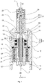
- the 1 shows a schematic partial sectional view of an embodiment of an eccentric screw pump 1 for dosing a liquid or pasty medium M.
- the medium M can be, for example, an alginate, a bone wax or any other biological or medical material.
- the medium M can contain human, animal or plant cells.
- the medium M can furthermore also include bacteria or viruses.
- a suitable medium M can be selected depending on the use of the eccentric screw pump 1 in biomedicine, pharmaceutical technology or industry.
- the medium M can also be a cyanoacrylate, for example.
- the medium M can also be an anaerobic adhesive.
- the eccentric screw pump 1 comprises a housing 2 with a front housing part 3 , a pump housing part 4 and a bearing housing part 5 .
- the pump housing part 4 is arranged between the front housing part 3 and the bearing housing part 5 .
- the housing 2 also includes a rear housing part (not shown).
- the front housing part 3, the pump housing part 4 and/or the bearing housing part 5 can be firmly connected to one another, for example screwed.
- the front housing part 3, the pump housing part 4 and the bearing housing part 5 can preferably be dismantled from one another, for example for cleaning purposes.
- the housing 2 is constructed essentially rotationally symmetrically to a central axis or axis of symmetry 6 .
- the bearing housing part 5 comprises a centrally arranged bore 7, in which a first bearing element 8 and a second bearing element 9 are accommodated.
- the bearing elements 8, 9 can be plain bearings, for example. Alternatively, the bearing elements 8, 9, as in the 1 shown to be rolling bearings. Facing the pump housing part 4, the first bearing element 8 lies on a bore 7 protruding paragraph 10 of the bearing housing part 5 at.
- a groove 11 running around the axis of symmetry 6 is provided in the bearing housing part 5 facing away from the pump housing part 4 .
- a retaining ring 12 is accommodated in the groove 11 and fixes the bearing elements 8 , 9 on the bearing housing part 5 .
- a sealing element 13 which is pressed between the pump housing part 4 and the bearing housing part 5 , is accommodated between the bearing housing part 5 and the pump housing part 4 .
- a groove running around the axis of symmetry 6 in a ring shape is provided in the shoulder 10 .
- the bearing housing part 5 can be made of a metallic material such as steel or aluminum. Alternatively, the bearing housing part 5 can also be made from a plastic material.
- the pump housing part 4 comprises a receiving space 14 provided centrally in the pump housing part 4 for receiving the medium M.
- the receiving space 14 is constructed rotationally symmetrically to the axis of symmetry 6 .
- the medium M can be fed to the receiving space 14 via a feed opening 15 designed as a bore provided in the pump housing part 4 .
- the feed opening 15 can be oriented obliquely or perpendicularly to the axis of symmetry 6 .
- a replaceable cartridge that holds the medium M can be connected to the feed opening 15, for example.
- a sealing surface 16 running around the axis of symmetry 6 in a cylindrical manner adjoins the receiving space 14 .
- the sealing elements 17, 18 are mounted on the sealing surface 16 .
- the sealing elements 17, 18 can be shaft sealing rings, for example. However, the sealing elements 17, 18 can also be O-rings.
- the pump housing part 4 projects into the front part 3 of the housing with a projection 19 which is of cylindrical design.
- the receiving space 14 extends through the projection 19 .
- the front housing part 3 includes a central bore 20 in which the projection 19 of the pump housing part 4 is accommodated.
- the pump housing part 4 is preferably made of a metallic material such as steel or aluminum. Alternatively, the pump housing part 4 can also be made of a plastic material.
- the eccentric screw pump 1 also includes an at least partially elastically deformable stator 21 .
- the stator 21 has an outer part 22 and an inner part 23 accommodated in the outer part 22 .
- the outer part 22 comprises a foot section 24 which is arranged between the bearing housing part 4 and the front part 3 of the housing, in particular between the projection 19 and the bore 20 .
- the stator 21 can be detachably connected to the housing 2 with the aid of the housing front part 3 .
- the outer part 22 On the front side, ie facing away from the front part 3 of the housing, the outer part 22 includes a Luer lock connector 25. With the help of the Luer lock connector 25, for example, a cannula can be connected to the eccentric screw pump 1.
- the inner part 23 is preferably an elastically deformable elastomeric part with a central opening 26.
- the opening 26 preferably comprises a helical or snail-shaped inner contour.
- the inner part 23 is made of an elastomer such as rubber or a thermoplastic elastomer (TPE).
- TPE thermoplastic elastomer
- the outer part 22 is preferably made of a harder plastic material than the inner part 23 .
- the outer part 22 can also be made of a metallic material, such as stainless steel or aluminum.
- the eccentric screw pump 1 also has a rotor unit 27 .
- the rotor unit 27 can also be referred to as a rotor train or compact rotor train.
- the rotor unit 27 includes a drive shaft 28 which is rotatably mounted in the bearing housing part 5 with the aid of the bearing elements 8 , 9 .
- the drive shaft 28 can be rotated about the axis of symmetry 6 with the aid of a drive element 29 .
- the drive element 29 can be an electric motor.
- the drive element 29 can have a gear, for example a planetary gear.
- the drive element 29 is coupled to the drive shaft 28 in any manner such that the drive element 29 can apply torque to the drive shaft 28 .
- the drive element 29 is accommodated in the housing 2, in particular in the rear part of the housing (not shown).
- the rotor unit 27 includes a rotor 30 which is snail-shaped and thus has a helical or snail-shaped outer contour which corresponds to the snail- or snail-shaped inner contour of the opening 26 in the inner part 23 of the stator 21 .
- the rotor 30 can be made from a metallic material, for example stainless steel, or from a suitable plastic material.
- a flex shaft 31 is provided between the rotor 30 and the drive shaft 28 and connects the rotor 30 to the drive shaft 28 .
- the flex shaft 31 is viewed along a longitudinal direction L of the rotor unit 27, which is oriented from the drive shaft 28 in the direction of the rotor 30 and parallel to the axis of symmetry 6, and is accommodated at least in sections within the drive shaft 28.
- the flex shaft 31 can also be referred to as a flexible shaft.
- the flex shaft 31 is preferably elastically deformable and enables an eccentric movement of the rotor 30 in the stator 21.
- the flex shaft 31 serves to transmit torque from the drive shaft 28 to the rotor 30.
- the flex shaft 31 can be a wire cable which is coated or sheathed with a plastic material, for example.
- the flex shaft 31 can also include one or more joints, in particular a universal joint or cardan joint, which also enable an eccentric movement of the rotor 30 .
- the flex shaft 31 itself is not elastically deformable, and the eccentric movement of the rotor 30 is made possible purely by the joint or joints.
- the flex shaft 31 can also be a flexible rod, in particular a plastic flexible rod, or be referred to as such.
- the flex shaft 31 can be made of a polyetheretherketone (PEEK), polyethylene (PE) or the like, for example.
- PEEK polyetheretherketone
- PE polyethylene
- the flex shaft 31 can have a diameter of 3 mm or less, for example.
- the rotor 30 can have a diameter of 2 mm, 1.7 mm or 1.5 mm.
- the rotor 30 can also have a larger or smaller diameter.
- the rotor 30 and the flexible shaft 31 can, for example, be designed in one piece, in particular in one piece of material. "In one piece” or “in one piece” means here that the flex shaft 31 and the rotor 30 form a common component and are not composed of different components. "One-piece material” means here that the flex shaft 31 and the rotor 30 are made of the same material throughout.
- the drive shaft 28 can also be formed in one piece, in particular in one piece of material, with the flexible shaft 31 and/or the rotor 30 .
- the rotor unit 27 is preferably a plastic component.
- the rotor unit 27 can be a one-piece plastic injection molded component.
- the flex shaft 31, the rotor 30 and/or the drive shaft 28 can also be separate components which, for example, are plugged into one another and are thus either detachably or non-detachably connected to one another.
- the flexible shaft 31 can be made of a metallic material and the rotor 30 can be made of a plastic, or vice versa.
- the flex shaft 31 can be coated with an elastomer.
- the rotor 30 can also be made of a metallic material.
- the rotor 30 can be made of stainless steel, for example.
- the rotor 30 can also be designed as a plastic component or a ceramic component and can have various coatings.
- the medium M is conveyed away from the drive shaft 28 in the longitudinal direction L by the interaction with the opening 26 in the stator 21 according to the endless piston principle.
- the delivery volume per unit of time is dependent on the speed, size, pitch and geometry of the rotor 30.
- Such an eccentric screw pump 1 is particularly suitable for conveying a large number of media M, in particular viscous, highly viscous and abrasive media M.
- the progressing cavity pump 1 belongs to the group of rotating displacement pumps.
- the main components of the progressing cavity pump 1 are the drive element 29, the rotatable rotor unit 27 and the fixed stator 21, in which the rotor 30 rotates.
- the rotor 30 is designed as a type of round thread screw with an extremely large pitch, large thread depth and small core diameter.
- the at least partially elastically deformable stator 21 preferably has one more thread turn than the rotor 30 and twice the pitch length of the rotor 30. This leaves pumping spaces between the stator 21 and the rotor 30 rotating therein and also moving radially, which continuously extend from an inlet side of the Stators 21 move to an exit side thereof. Valves to limit the pumping chambers are not required.
- the size of the delivery chambers and thus the theoretical delivery rate depends on the pump size.
- a 360° rotation of the rotor unit 27 with a free outlet gives the volumetric delivery rate per revolution.
- the flow rate of the eccentric screw pump 1 can thus be changed via the speed of the rotor unit 27 .
- the actual flow rate depends on the back pressure that occurs.
- the medium M to be dosed always tries to equalize the pressure from the high to the low pressure. Since the seal between the rotor 30 and the stator 21 is not static, medium M will always flow from the pressure side to the suction side. These "slip losses" can be seen on the basis of a characteristic curve as the difference between the theoretical and the actual flow rate.
- the shape of the pumping chambers is constant, so that the medium M is not compressed. With a suitable design, not only fluids but also solids can therefore be conveyed with such an eccentric screw pump 1 .
- the shearing forces acting on the medium M are very small, so that, for example, plant, animal and human cells can also be conveyed in a non-destructive manner.
- a particular advantage of such an eccentric screw pump 1 is that the eccentric screw pump 1 delivers continuously and with little pulsation. This makes them suitable for use in potting plants. Even highly viscous and abrasive media can be pumped without any problems.
- the eccentric screw pump 1 With the help of the eccentric screw pump 1, a wide variety of media M can thus be conveyed gently and with low pulsation.
- the spectrum of the media M ranges from water to media M that no longer flow by themselves. Since the flow rate is proportional to the speed of the rotor 30, the eccentric screw pump 1 can be used very well for dosing tasks in conjunction with appropriate measurement and control technology.
- the progressing cavity pump 1 combines many positive properties of other pump systems. Like the centrifugal pump, the progressing cavity pump 1 has no suction and pressure valves. Like the piston pump, the progressive cavity pump 1 has excellent self-priming performance. Like the diaphragm or peristaltic pump, the eccentric screw pump 1 can have any type of inhomogeneous and promote abrasive media M, which can also be mixed with solids and fibrous materials.
- the eccentric screw pump 1 Like the gear or screw pump, the eccentric screw pump 1 is able to cope with the highest viscosities of the medium M. Like the piston, membrane, gear or screw pump, the progressing cavity pump 1 has a speed-dependent, continuous delivery flow and is therefore able to perform high-precision dosing tasks.
- the eccentric screw pump 1 can be used in all industrial sectors in which special conveying tasks have to be solved.
- Examples are environmental technology, especially pumping in the area of sewage treatment plants, the food industry, especially for high-viscosity media such as syrup, quark, yoghurt and ketchup, in the various low-germ processing stages, and the chemical industry, especially for safe pumping and dosing of aggressive, high-viscosity media and abrasive media M.
- eccentric screw pump 1 With the eccentric screw pump 1 the exact dosing of different media M is possible. A repeatability of ⁇ 1% can be achieved.
- Various embodiments of the eccentric screw pump 1 also enable the application of two-component media M. Due to its design, namely that the rotor 30 moves in the medium M and an internal volume of the suction side must be filled, such an eccentric screw pump 1 always has a certain dead space. This dead space can be reduced by arranging the flexible shaft 31 within the drive shaft 28, so that there is a reduction in installation space along the longitudinal direction L. In this way, the receiving space 14 in particular can be made smaller.
- the rotor assembly 27 includes the flex shaft 31 which is elastically deformable. This allows the rotor 30 to move eccentrically in the stator 21. During this eccentric movement of the rotor 30 in the stator 21, the flex shaft 31 performs a radial movement within the drive shaft 28 along a radial direction R of the rotor unit 27.
- the radial direction R is perpendicular to the Longitudinal direction L and oriented away from this.
- the stator 21 is exposed to a continuous load during operation, which is why it is subject to wear. This wear is compensated for by regularly replacing the stator 21, with the replacement intervals being determined by the media M used and the process parameters.
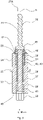
- the 2 shows a schematic view of a further embodiment of a rotor unit 27A for the eccentric screw pump 1.
- FIG 3 12 shows a schematic sectional view of the rotor unit 27A. The following will refer to the 2 and 3 referenced at the same time.
- the rotor assembly 27A includes a drive shaft 28, a rotor 30, and a flexshaft 31 connecting the rotor 30 to the drive shaft 28.
- the drive shaft 28 includes an interface 32 by which the rotor assembly 27A can be coupled to the drive member 29.
- the drive element 29 can transmit a torque to the rotor unit 27A with the aid of the interface 32 .
- Torque is transmitted from the drive shaft 28 to the flexshaft 31 and from the flexshaft 31 to the rotor 30 .
- the drive shaft 28, the flexible shaft 31 and the rotor 30 are connected to one another in a rotationally fixed manner.
- the drive shaft 28 includes a bearing surface 33 on which the bearing elements 8, 9 can be mounted, as well as a sealing surface 34.
- the sealing elements 17 , 18 can rest against the sealing surface 34 in a sealing manner.
- a circumferential step 35 is provided between the bearing surface 33 and the sealing surface 34 viewed in the longitudinal direction L, which extends out both over the bearing surface 33 and over the sealing surface 34 viewed in the radial direction R.
- the drive shaft 28 also includes a recess 36 in which the flex shaft 31 is accommodated.
- the recess 36 has a first end 37 facing away from the rotor 30 and a second end 38 facing the rotor 30 .
- the recess 36 widens from the first end 37 in the direction of the second end 38, so that the recess 36 has a smaller diameter at the first end 37 than at the second end 38.
- the recess 36 can for this purpose, as in FIG 3 shown, be designed as a stepped bore. However, the recess 36 can also have a conical or frustoconical geometry.
- the drive shaft 28 also includes a first end face 39 facing the rotor 30 and a second end face 40 facing away from the rotor 30.
- the drive shaft 28 has an interface 41, with the help of which the flex shaft 31 is connected to the drive shaft 28 in a torque-proof manner.
- the interface 41 can, for example, comprise an adhesive connection, a screw connection, a soldered connection, a welded connection or the like.
- the flexible shaft 31 is preferably designed as a steel cable.
- the flex shaft 31 can also be made of a plastic material.
- a gap 42 running completely around the flex shaft 31 is provided between the flex shaft 31 and the drive shaft 28 .
- the gap 42 can be an air gap be.
- the gap 42, as in FIG 3 shown, also be filled with a sealant 43.
- the sealing compound 43 is elastically deformable, so that it does not impede the radial movement of the flex shaft 31 in the gap 42 or only insignificantly.
- a material with a low Shore hardness can be used for the sealing compound 43 .
- sealing compound 43 can be a silicone, in particular a two-component silicone, a silicone that cures at room temperature or RTV silicone (Room Temperature Vulcanizing Silicone), a silicone that cures at high temperatures, a thermoplastic elastomer (TPE), in particular a thermoplastic Polyurethane (TPU), a thermoplastic vulcanizate (TPV), a fluorovinyl methyl silicone rubber (FVMQ) or the like.
- TPE thermoplastic elastomer
- TPU thermoplastic Polyurethane
- TPV thermoplastic vulcanizate
- FVMQ fluorovinyl methyl silicone rubber
- the sealing compound 43 can also be foamed, for example.
- the sealing compound 43 can have an open-pore or a closed-pore structure.
- the sealing compound 43 can be foam rubber-like.
- the rotor 30 is preferably made of steel, in particular stainless steel. However, the rotor 30 can also be made of a plastic material.
- the rotor 30 includes an outer contour 44, as previously mentioned, which is helical or snail shaped. Facing the drive shaft 28, the rotor 30 includes a circumferential shoulder 45.
- the rotor 30 also includes a receiving section 46, which is sleeve-shaped and accommodates the flex shaft 31 at least in sections. For example, the flexible shaft 31 is glued, soldered or welded to the receiving section 46 .
- the sealing element 47 is provided between shoulder 45 and end face 39 of drive shaft 28 .
- the sealing element 47 can be made of rubber, for example.
- the sealing element 47 can also be made of a thermoplastic elastomer (TPE), in particular a thermoplastic polyurethane (TPU).
- TPE thermoplastic elastomer
- TPU thermoplastic polyurethane
- the sealing element 47 has a conical or frusto-conical geometry.
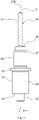
- the 4 shows a schematic view of a further embodiment of a rotor unit 27B for the eccentric screw pump 1.
- FIG figure 5 shows a schematic sectional view of the rotor unit 27B. The following will refer to the 4 and 5 referenced at the same time.
- the rotor unit 27B differs from the rotor unit 27A only in that instead of the cone-shaped or cone-shaped sealing element 47 according to the 2 and 3 a disc-shaped sealing element 47 is provided. Otherwise, the structure of the rotor unit 27B corresponds to the structure of the rotor unit 27A.
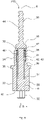
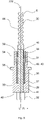
- the 6 shows a schematic view of a further embodiment of a rotor unit 27C for the eccentric screw pump 1.
- the 7 shows a schematic sectional view of the rotor unit 27C. The following will refer to the 6 and 7 referenced at the same time.
- the rotor unit 27C differs from the rotor unit 27A only in that instead of the cone-shaped or cone-shaped sealing element 47 according to FIGS 2 and 3 a bellows-shaped sealing element 47 is provided. Furthermore, the rotor unit 27C does not include any sealing compound 43 accommodated in the gap 42. Optionally, however, the rotor unit 27C can also have the sealing compound 43.
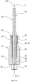
- the 8 shows a schematic sectional view of a further embodiment of a rotor unit 27D.
- the rotor unit 27D differs from the rotor unit 27A only in that instead of the cone-shaped or cone-shaped sealing element 47 according to FIGS 2 and 3 a sealing element 47 in Form of an O-ring is provided. Otherwise, the structure of the rotor unit 27D corresponds to the structure of the rotor unit 27A.
- the 9 shows a schematic sectional view of a further embodiment of a rotor unit 27E.
- the rotor unit 27E differs from the rotor unit 27A only in that the rotor 30 has no circumferential shoulder 45 and that no additional sealing element 47 is provided. Otherwise, the construction of the rotor unit 27C corresponds to that of the rotor unit 27A.
- the 10 shows a schematic sectional view of a further embodiment of a rotor unit 27F.
- the rotor unit 27F differs from the rotor unit 27E only in that the rotor 30 and the flex shaft 31 are not two separately manufactured components which are firmly connected to one another, but form a one-piece component, in particular a one-piece material component.
- the rotor 30 and the flex shaft 31 are designed as a one-piece plastic injection molded component.
- the flex shaft 31 is a flexible rod, in particular a plastic flexible rod.
- the drive shaft 28 can also be designed in one piece, in particular in one piece of material, with the rotor 30 and the flexible shaft 31 .
- the entire rotor unit 27F is a one-piece plastic component, in particular a plastic injection molded component.
- the rotor assembly 27F may be manufactured using a multi-component plastic injection molding process, so that it is possible to manufacture the drive shaft 28, flexshaft 31 and rotor 30 as a one-piece component with different plastic materials.
- the 11 shows a schematic sectional view of a further embodiment of a rotor unit 27G.
- the rotor assembly 27G differs from that Rotor unit 27F only in that the rotor unit 27G has no sealing compound 43. That is, the gap 42 surrounding the flex shaft 31 is an air gap.
- the omission of the sealing compound 43 has the advantage that an additional work step of filling in the sealing compound 43 can be dispensed with.
- the rotor unit 27G can then be produced as a plastic injection-molded component without further post-processing in the form of casting the gap 42 with the sealing compound 43 .
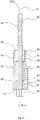
- the 12 shows a schematic sectional view of a further embodiment of a rotor unit 27H.
- the rotor unit 27H differs from the rotor unit 27G only in that a first sealing lip 48 and a second sealing lip 49 are formed on the drive shaft 28, in particular on the sealing surface 34.
- the sealing lips 48, 49 are suitable for sealing radially with respect to the sealing surface 16 of the pump housing part 4.
- the sealing lips 48, 49 are molded onto the drive shaft 28 in a plastic injection molding process.
- the sealing lips 48, 49 can be made of the same material as the drive shaft 28.
- the sealing lips 48, 49 can also be made of a different material than the drive shaft 28.
- a multi-component injection molding process can be used for this purpose, for example.
- the rotor unit 27, 27A, 27B, 27C, 27D, 27E, 27F, 27G, 27H can be a disposable item. However, this is not mandatory. Alternatively, the rotor unit 27, 27A, 27B, 27C, 27D, 27E, 27F, 27G, 27H can also be used several times.
- Disposable process solutions also known as single-use technologies, are used in particular to manufacture biopharmaceutical products.
- Various media M are required for biotechnical processes. These include nutrient solutions, cells, buffers for stabilizing the pH value, as well as acids and bases for adjusting and regulating the pH value during cultivation. All media M used must be sterilized before use. For this purpose, two main processes are used in biotechnology: heat sterilization at at least 121 °C at 1 bar overpressure for at least 20 minutes and sterile filtration. Sterile filtration is the method of choice for media M that contain heat-sensitive components such as vitamins, proteins and peptides.
- the disposable process solutions available are each to be regarded as a self-contained module.
- the basic process engineering operations required for the production and purification of the target product are connected in series.
- the pre-configured single-use systems which consist of hoses, single-use tanks, pump heads and filtration or chromatography modules, are self-contained. Sterile connection technologies, usually hose connections, are therefore required to connect two consecutive process steps.
- thermoplastic hoses can be welded together in a sterile manner or existing connections can be severed and the hose ends can be welded.
- Special rapid transfer systems have been developed for connection through a wall.
- hybrid processes in which single-use systems are combined with conventional stainless steel and glass systems.
- closed systems in which the one-way systems are linked together in the order of the process steps, and station systems, in which the intermediate products are transported to the next process step using mobile containers.
- single use (often also referred to as “disposable”) defines an item that is intended for single use. Usually this consists of a plastic material such as polyamide (PA), polycarbonate (PC), polyethylene (PE), polyethersulfone (PESU), polyoxymethylene (POM), polypropylene (PP), polytetrafluoroethylene (PTFE), polyvinyl chloride (PVC) , cellulose acetate (CA) or ethylene vinyl acetate (EVA), and is discarded after use.
- the rotor unit 27, 27A, 27B, 27C, 27D, 27E, 27F, 27G, 27H can consist of one or more of the be made of the aforementioned materials.
- Single-use technology SUT
- SUS single-use technology
- the eccentric screw pump 1 can be used in particular for additive or generative manufacturing. That is, the progressive cavity pump 1 is a 3D print head or can be referred to as such. 3D printing is a comprehensive term for all manufacturing processes in which material can be applied layer by layer to create three-dimensional objects.
- the layered structure is computer-controlled from one or more liquid or solid materials according to specified dimensions and shapes.
- 3D printing Physical or chemical hardening or melting processes take place during construction.
- Typical materials for 3D printing are plastics, synthetic resins, ceramics and metals.
- carbon and graphite materials have also been developed for 3D printing carbon parts.
- it is a primary forming process no special tools are required for a specific product that have stored the respective geometry of the workpiece, such as casting molds.
- 3D printers are used in industry, model making and research to produce models, samples, prototypes, tools, end products or the like. Furthermore, these are also used for private use. There are also applications in home and entertainment, construction, and art and medicine.
- 3D printing has the advantage that the time-consuming production of molds and mold changes are no longer necessary.
- 3D printing has the advantage that there are no additional processing steps after the primary shaping. In most cases, the process is energetically cheaper, especially if the material is only built up once in the required size and mass.
- post-processing may be necessary depending on the area of application.
- the media M can be, for example, silicones, polyurethanes, ceramic and metal pastes, epoxy resins and acrylates.
- the advantages of the progressing cavity pump 1 over other technologies capable of printing liquids are its applicability for high viscosities, the high precision and process stability, the large range of materials that can be used and the high application speed.
- Other technologies are dependent on material adjustments, some of which are strong, in order to achieve a meaningful printing process.
- light-based technologies for liquids always depend on the presence of a photon crosslinker, whereas the progressing cavity pump 1 can print completely independently of the curing mechanism.
- the eccentric screw pump 1 can be used for so-called “bioprinting”.
- bioprinting The field of application of bioprinting is still very young and represents the latest step in cell culture technology. It can be seen as a special form of additive manufacturing at the interface between medical technology and biotechnology.
- the topic of bioprinting is often introduced with words about the great need for donor organs. It is essential that tissue and organs are artificially produced in the future in order to meet the enormous demand. Realistically, this vision is still a long way off if it should ever become reality.
- mini-organs are printed, which depict all the essential functions of a real organ be able. Using microfluidic techniques, these mini-organs can be combined into multi-organ systems and the systemic effects of active substances can thus be tested without the need for animal experiments.
- cell-loaded gels or matrices are produced for maintaining and cultivating the same with the aid of the eccentric screw pump 1, in particular with the aid of a bioprinter.
- This is done through a layered structure, which is known from additive manufacturing. Since most media M are loaded with living cells during bioprinting, which can only be produced with considerable expenditure of time and money, careful application is essential.
- the stress on the deployed cells increases with the cell density and the viscosity of the medium M. For meaningful constructs, however, the highest possible cell density and stability are required. This creates a tension between cell concentration and application technology.
- the materials for the eccentric screw pump 1 are chosen so that they are as light as possible.
- the housing 2 can be partially made of metal or plastic. Since the components rotor unit 27, 27A, 27B, 27C, 27D, 27E, 27F, 27G, 27H and stator 21 can be made of a plastic material, the weight is further reduced. Due to the reduced installation space of the rotor unit 27, 27A, 27B, 27C, 27D, 27E, 27F, 27G, 27H along the longitudinal direction L, a weight reduction can also be achieved.
- eccentric screw pump 1 in the field of bioprinting
- other areas of application are also conceivable.
- the use of the progressing cavity pump 1 does not have to be limited to bioprinting.
- the printing of materials such as silicones, epoxy resins, polyurethanes, Ceramic, metal and solder pastes are also possible. With a compact design, it is also conceivable to open up the market for amateur 3D printers.
- a rotor unit 27, 27A, 27B, 27C, 27D, 27E, 27F, 27G, 27H designed as a disposable article, which can be quickly replaced in the event of a malfunction without major damage, is therefore advantageous.
- the eccentric screw pump 1 can be used for the precise application of the medium M in wound care, in the body, in operations, in dental treatments or for the delivery of medication.
- An example of an interface between additive manufacturing and medical technology is the printing of tablets. Problems with interactions, overdosing and underdosing as well as forgetting to take a tablet can be counteracted by individually creating tablets with patient-specific active ingredients and active ingredient contents.
- the eccentric screw pump 1 can also be used for printing tablets.
- the eccentric screw pump 1 can also be used for micro dosing in the production of film tablets, for dosing vaccines, active ingredients, particularly expensive active ingredients, or for plaster application by dosing.
- the progressing cavity pump 1 can also be used for micro dosing in aseptic applications.
- the progressing cavity pump can also be used for the production of very small components, for example for gluing endoscopes 1 find application.
- the eccentric screw pump 1 can be used for dispensing expensive active ingredients, either in a continuous or discontinuous process. It is also possible to produce personalized tablets, especially film-coated tablets. It is also possible to use several active ingredients in one tablet, in particular a film tablet, or on active plasters.
- the eccentric screw pump 1 can also be used in cosmetics, in particular in personalized cosmetics, for dosing very small quantities.
- the eccentric screw pump 1 can be mains operated or battery operated. This means that battery operation of the eccentric screw pump 1 is possible. As a result, the eccentric screw pump 1 is independent of a power grid.
- the eccentric screw pump 1 can thus work independently as a handheld device.
- the eccentric screw pump 1 can be used to meter soldering paste at a manual workstation.
- the eccentric screw pump 1 can thus be used in the manner of a pipetting device or pipetting aid, with the difference that the eccentric screw pump 1 can also be used to dose highly viscous media M.
- such a self-sufficient eccentric screw pump 1 can also be used to treat quick wounds, for example for field treatment by emergency services, in doctors' surgeries or in the operating room.
- the media M that can be dosed are, for example, waxes, in particular bone waxes, adhesives, medicaments, denture materials, artificial skin or the like.
Landscapes
- Engineering & Computer Science (AREA)
- Mechanical Engineering (AREA)
- General Engineering & Computer Science (AREA)
- Rotary Pumps (AREA)
Abstract
Description
- Die vorliegende Erfindung betrifft eine Rotoreinheit für eine Exzenterschneckenpumpe und eine Exzenterschneckenpumpe, insbesondere einen 3D-Druckkopf, mit einer derartigen Rotoreinheit.
- Exzenterschneckenpumpen umfassen einen Stator sowie einen drehbar in dem Stator aufgenommenen Rotor. Bei einem Drehen des Rotors wird ein zu dosierendes Medium durch das Zusammenspiel des Rotors mit dem Stator in einer Längsrichtung der Exzenterschneckenpumpe weg von einem Antriebselement der Exzenterschneckenpumpe nach dem Endloskolbenprinzip gefördert. Das Fördervolumen pro Zeiteinheit ist dabei abhängig von der Drehzahl, der Größe, der Steigung und der Geometrie des Rotors. Mit derartigen Exzenterschneckenpumpen sind hochpräzise Dosiervorgänge mit einer hohen Wiederholgenauigkeit möglich.
- Im Betrieb einer derartigen Exzenterschneckenpumpe führt der Rotor eine exzentrische Bewegung in dem Stator durch. Um diese exzentrische Bewegung zu ermöglichen, ist der Rotor über eine flexibel verformbare Welle oder ein Gelenk mit einer Antriebswelle verbunden. Hieraus ergibt sich in der Längsrichtung der Exzenterschneckenpumpe betrachtet ein relativ großer Bauraum. Dieser Bauraum bedingt ein großes Totvolumen in einem Pumpengehäuse der Exzenterschneckenpumpe. Gerade bei kostenintensiven Medien ist es wünschenswert, dass dieses Totraumvolumen so klein wie möglich ist.
- Die
DE 20 2007 018 923 U1 beschreibt eine wie zuvor erwähnte Exzenterschneckenpumpe, welche eine Rotoreinheit mit einer Antriebswelle, einem Rotor und einer zwischen der Antriebswelle und dem Rotor angeordneten flexiblen Welle aufweist. - Vor diesem Hintergrund besteht eine Aufgabe der vorliegenden Erfindung darin, eine verbesserte Rotoreinheit für eine Exzenterschneckenpumpe zur Verfügung zu stellen.
- Demgemäß wird eine Rotoreinheit für eine Exzenterschneckenpumpe vorgeschlagen. Die Rotoreinheit umfasst eine Antriebswelle, welche mit Hilfe eines Antriebselements der Exzenterschneckenpumpe antreibbar ist, einen schneckenförmigen Rotor und eine Flexwelle, welche die Antriebswelle mit dem Rotor verbindet, wobei die Flexwelle zumindest abschnittsweise innerhalb der Antriebswelle aufgenommen ist, und wobei zwischen der Flexwelle und der Antriebswelle ein um die Flexwelle umlaufender Spalt vorgesehen ist, welcher eine Radialbewegung der Flexwelle innerhalb der Antriebswelle ermöglicht.
- Dadurch, dass die Flexwelle zumindest abschnittsweise innerhalb der Antriebswelle aufgenommen ist, kann entlang einer Längsrichtung der Rotoreinheit, welche von der Antriebswelle in Richtung des Rotors orientiert ist, ein verkürzter Bauraum erzielt werden. Hierdurch ist es möglich, die Exzenterschneckenpumpe konstruktiv derart zu gestalten, dass diese ein minimales Totvolumen aufweist. Dies ist insbesondere bei der Dosierung kostenintensiver Medien vorteilhaft.
- Die Rotoreinheit kann auch als Rotorstrang, insbesondere als Kompaktrotorstrang, bezeichnet werden. Die Begriffe "Rotoreinheit", "Rotorstrang" und "Kompaktrotorstrang" können beliebig gegeneinander getauscht werden. Die Rotoreinheit ist vorzugsweise Teil der Exzenterschneckenpumpe. Die Rotoreinheit ist auswechselbar. Die Antriebswelle ist insbesondere in einem Lagergehäuseteil der Exzenterschneckenpumpe drehbar um eine Symmetrieachse der Rotoreinheit gelagert. Hierzu können Lagerelemente in Form von Wälzlagern oder Gleitlagern vorgesehen sein. Das Antriebselement kann ein Elektromotor sein. Das Antriebselement kann ein Getriebe, beispielsweise ein Planetengetriebe, umfassen. Das Antriebselement ist insbesondere geeignet, ein Drehmoment auf die Rotoreinheit aufzubringen. Die Antriebswelle überträgt das Drehmoment auf die Flexwelle, welche das Drehmoment wiederum auf den Rotor überträgt.
- Der Rotor ist mit Hilfe der Flexwelle fest mit der Antriebswelle verbunden. Vorderseitig an der Flexwelle ist der Rotor vorgesehen, welcher mit einem Stator der Exzenterschneckenpumpe zusammenwirkt. Dass der Rotor "schneckenförmig" ist, bedeutet vorliegend insbesondere, dass der Rotor eine schrauben- oder schneckenförmige Außenkontur aufweist. Die Begriffe "schraubenförmig" und "schneckenförmig" sind beliebig gegeneinander austauschbar. Im Betrieb der Exzenterschneckenpumpe arbeitet der Rotor mit dem Stator zusammen, welcher einen Durchbruch aufweist, in dem der Rotor angeordnet ist. Der Durchbruch des Stators weist eine zu dem Rotor korrespondierende schrauben- oder schneckenförmige Innenkontur auf. Der Stator ist ebenfalls Teil der Exzenterschneckenpumpe. Der Stator ist austauschbar.
- Unter einer "Flexwelle" ist vorliegend eine Welle, insbesondere allgemeiner ein Bauteil, zu verstehen, welches eine exzentrische Bewegung des Rotors gegenüber der Antriebswelle erlaubt. Die Flexwelle kann hierzu beispielsweise ein Gelenk, insbesondere ein Kreuzgelenk oder ein Kardangelenk, oder mehrere Gelenke aufweisen. Die Flexwelle kann auch als Biegewelle oder Gelenkwelle bezeichnet werden. Besonders bevorzugt ist die Flexwelle jedoch selbst elastisch verformbar. Es ist jedoch nicht zwingend erforderlich, dass die Flexwelle selbst flexibel verformbar ist. Die Flexwelle kann auch ein Biegestab, insbesondere ein Kunststoffbiegestab, sein oder als solcher bezeichnet werden. In diesem Fall kann die Flexwelle beispielsweise aus einem Polyetheretherketon (PEEK), Polyethylen (PE) oder dergleichen gefertigt sein. Alternativ kann die Flexwelle auch aus einem, insbesondere kunststoffbeschichten, Stahlseil gefertigt sein.
- Der Rotor ist über die Flexwelle an die Antriebswelle angebunden, welche im Betrieb der Exzenterschneckenpumpe mit Hilfe des Antriebselements angetrieben wird. Bei dem Drehen des Rotors in dem Stator wird ein zu dosierendes oder zu förderndes Medium durch das Zusammenspiel mit dem Stator, insbesondere dem Durchbruch des Stators, in der Längsrichtung der Exzenterschneckenpumpe weg von der Antriebswelle nach dem Endloskolbenprinzip gefördert. Das Fördervolumen pro Zeiteinheit ist dabei abhängig von der Drehzahl, der Größe, der Steigung und der Geometrie des Rotors.
- Dass die Flexwelle "innerhalb" der Antriebswelle aufgenommen ist, bedeutet vorliegend, dass die Flexwelle zumindest abschnittsweise durch die Antriebswelle hindurchgeführt ist. Zwischen der Flexwelle und der Antriebswelle ist der vorzugsweise vollständig um die Flexwelle herumlaufende Spalt vorgesehen. Wie zuvor erwähnt, vollführt der Rotor eine exzentrische Bewegung, welche dazu führt, dass die innerhalb der Antriebswelle angeordnete Flexwelle in einer Radialrichtung, welche senkrecht zu der Symmetrieachse der Rotoreinheit orientiert ist, ausgelenkt wird. Die Radialbewegung kann ebenfalls eine exzentrische Bewegung sein. Dies ist jedoch nicht zwingend.
- Das zu dosierende Medium kann beispielsweise ein Kleb- oder Dichtstoff, Wasser, eine wässrige Lösung, eine Farbe, eine Suspension, ein viskoser Rohstoff, eine Emulsion oder ein Fett sein. Das Medium kann auch ein Gel oder Alginat sein. Das Medium kann Zellen, insbesondere menschliche, tierische oder pflanzliche Zellen, umfassen. Das Medium kann flüssig oder pastös sein. Unter einer Paste oder einem pastösen Medium ist ein Feststoff-Flüssigkeitsgemisch, insbesondere eine Suspension, mit einem hohen Gehalt an Festkörpern zu verstehen. Beispielsweise kann das Medium einen Gehalt an Füllstoffen, beispielsweise sogenannte Microballoons, faserige, insbesondere kurzfaserige, Anteile oder dergleichen aufweisen. Das Medium kann beispielsweise ein Alginat, ein Knochenwachs oder ein beliebiges anderes biologisches oder medizinisches Material sein. Das Medium kann weiterhin auch Bakterien oder Viren umfassen. Je nach Einsatz der Exzenterschneckenpumpe in der Biomedizin, Pharmatechnik oder Industrie kann ein geeignetes Medium gewählt werden. Das Medium kann beispielsweise auch ein Cyanacrylat sein. Das Medium kann auch ein anaerober Klebstoff sein.
- Gemäß einer Ausführungsform umfasst die Antriebswelle außenseitig eine zylinderförmige Lagerfläche, wobei die Flexwelle zumindest abschnittsweise innerhalb der Lagerfläche verläuft.
- Die Lagerfläche ist vorzugsweise rotationssymmetrisch zu der Symmetrieachse der Rotoreinheit aufgebaut. An der Lagerfläche können die zuvor erwähnten Lagerelemente, insbesondere Wälzlager oder Gleitlager, montiert werden. Dass die Flexwelle "innerhalb" der Lagerfläche verläuft, bedeutet vorliegend, dass die Flexwelle entlang der Radialrichtung betrachtet von der Lagerfläche umlaufen wird. Dies schließt jedoch nicht aus, dass die Flexwelle entlang der Längsrichtung betrachtet zumindest abschnittsweise über die Lagerfläche übersteht. Die Flexwelle kann auch zumindest abschnittsweise innerhalb einer Dichtfläche der Antriebswelle verlaufen. Auch die Dichtfläche ist bevorzugt zylinderförmig. Die Dichtfläche ist ebenfalls außenseitig an der Antriebswelle vorgesehen.
- Gemäß einer weiteren Ausführungsform umfasst die Antriebswelle eine Ausnehmung, in welcher die Flexwelle aufgenommen ist, wobei sich die Ausnehmung ausgehend von einem dem Rotor abgewandten ersten Ende der Ausnehmung hin zu einem dem Rotor zugewandten zweiten Ende der Ausnehmung aufweitet.
- Die Ausnehmung ist insbesondere eine in der Antriebswelle vorgesehene Bohrung. Die Ausnehmung erstreckt sich dabei entlang der Längsrichtung und ist vorzugsweise rotationssymmetrisch zu der Symmetrieachse aufgebaut. In der Ausnehmung ist die Flexwelle aufgenommen. Dies schließt jedoch nicht aus, dass die Flexwelle über die Antriebswelle übersteht. Die Flexwelle kann auch bezüglich der Antriebswelle zurückstehen. Dass sich die Ausnehmung "aufweitet" bedeutet vorliegend insbesondere, dass ein Durchmesser der Ausnehmung an dem zweiten Ende größer ist als an dem ersten Ende. Dies ermöglicht die Radialbewegung der Flexwelle, wobei die Radialbewegung an dem ersten Ende eine kleinere Amplitude aufweist als an dem zweiten Ende.
- Gemäß einer weiteren Ausführungsform ist die Ausnehmung gestuft oder konusförmig.
- "Gestuft" bedeutet vorliegend, dass die Ausnehmung eine Stufenbohrung ist, welche aus mehreren Bohrungsabschnitten mit unterschiedlichen Durchmessern aufgebaut ist. "Konusförmig" oder "kegelstumpfförmig" bedeutet vorliegend insbesondere, dass ein Durchmesser der Ausnehmung ausgehend von dem ersten Ende hin zu dem zweiten Ende kontinuierlich und ohne Stufen zunimmt.
- Gemäß einer weiteren Ausführungsform ist die Flexwelle an dem ersten Ende fest mit der Antriebswelle verbunden.
- Die Flexwelle kann formschlüssig mit der Antriebswelle verbunden sein. Hierzu kann die Antriebswelle eine Schnittstelle aufweisen. Eine formschlüssige Verbindung entsteht durch das Ineinander- oder Hintergreifen von zwei Verbindungspartnern, vorliegend der Flexwelle und der Antriebswelle. Beispielsweise kann die Flexwelle mit der Antriebswelle verschraubt sein. Die Flexwelle kann jedoch auch stoffschlüssig mit der Antriebswelle verbunden sein. Bei stoffschlüssigen Verbindungen werden die Verbindungspartner durch atomare oder molekulare Kräfte zusammengehalten. Stoffschlüssige Verbindungen sind nicht lösbare Verbindungen, die sich nur durch Zerstörung der Verbindungsmittel und/oder der Verbindungspartner trennen lassen. Beispielsweise ist die Flexwelle in die Antriebswelle eingeklebt, mit dieser verschweißt, insbesondere laserverschweißt, oder verlötet.
- Gemäß einer weiteren Ausführungsform ist der Spalt zumindest abschnittsweise mit einer elastisch verformbaren Dichtungsmasse gefüllt.
- Die Dichtungsmasse ist optional. Die Dichtungsmasse verhindert, dass das zu dosierende Medium in den Spalt hineingelangt. Die Dichtungsmasse ist vorzugsweise ein Material mit einer geringen Shore-Härte. Die Dichtungsmasse ist vorzugsweise derart elastisch verformbar, dass diese die Radialbewegung der Flexwelle in der Antriebswelle nicht oder zumindest nur geringfügig behindert. Beispielsweise kann Dichtungsmasse ein Silikon, insbesondere ein Zweikomponenten-Silikon, ein bei Raumtemperatur aushärtendes Silikon oder RTV-Silikon (Engl.: Room-Temperature-Vulcanizing Silicone), ein bei Hochtemperatur aushärtendes Silikon, ein thermoplastisches Elastomer (TPE), insbesondere ein thermoplastisches Polyurethan (TPU), ein thermoplastisches Vulkanisat (TPV), ein Fluor-Vinyl-Methyl-Silikon-Kautschuk (FVMQ) oder dergleichen sein oder umfassen.
- Gemäß einer weiteren Ausführungsform ist die Dichtungsmasse aufgeschäumt.
- Hierdurch wird die Verformbarkeit der Dichtungsmasse nochmals vergrößert. Beispielsweise kann die Dichtungsmasse eine offenporige oder eine geschlossenporige Struktur aufweisen. Die Dichtungsmasse kann moosgummiartig sein.
- Gemäß einer weiteren Ausführungsform umfasst die Rotoreinheit ferner ein Dichtungselement, welches stirnseitig zwischen der Antriebswelle und dem Rotor angeordnet ist.
- "Stirnseitig" bedeutet vorliegend zwischen einer Stirnfläche der Antriebswelle und dem Rotor, insbesondere einem Absatz des Rotors. Das Dichtungselement kann ein O-Ring sein. Das Dichtungselement kann auch scheibenförmig oder kegelstumpfförmig sein. Das Dichtungselement kann aus einem thermoplastischen Elastomer (TPE), insbesondere aus einem thermoplastischen Polyurethan (TPU), gefertigt sein. Das Dichtungselement kann auch aus Gummi gefertigt sein.
- Gemäß einer weiteren Ausführungsform umfasst der Rotor einen umlaufenden Absatz, wobei das Dichtungselement zwischen dem Absatz und einer Stirnfläche der Antriebswelle angeordnet ist.
- Insbesondere ist das Dichtungselement zwischen dem Absatz und der Stirnfläche verpresst. Das Dichtungselement verhindert das Eindringen des zu dosierenden Mediums in den zwischen der Flexwelle und der Antriebswelle vorgesehenen Spalt. Das heißt, dass die Dichtungsmasse verzichtbar ist, wenn das Dichtungselement vorgesehen ist. Dies schließt jedoch nicht aus, dass sowohl die Dichtungsmasse als auch das Dichtungselement vorgesehen sind.
- Gemäß einer weiteren Ausführungsform ist das Dichtungselement balgförmig.
- Hierdurch ist das Dichtungselement besonders leicht verformbar, wodurch die Radialbewegung der Flexwelle in der Antriebswelle nicht behindert wird. "Balgförmig" bedeutet vorliegend insbesondere, dass das Dichtungselement gefaltet ist oder zumindest eine Falte aufweist.
- Gemäß einer weiteren Ausführungsform ist die Flexwelle entlang einer Längsrichtung der Rotoreinheit betrachtet vollständig innerhalb der Antriebswelle aufgenommen.
- Das heißt, dass die Flexwelle entlang der Längsrichtung betrachtet nicht über die Antriebswelle übersteht. Alternativ kann die Flexwelle entlang der Längsrichtung betrachtet auch über die Antriebswelle überstehen. Die Flexwelle kann auch hinter der Antriebswelle zurückstehen.
- Gemäß einer weiteren Ausführungsform umfasst die Antriebswelle außenseitig zumindest eine, insbesondere einstückig mit der Antriebswelle ausgebildete, Dichtlippe zum Abdichten der Antriebswelle gegenüber einem Gehäuse der Exzenterschneckenpumpe.
- Die Anzahl der Dichtlippen ist beliebig. Beispielsweise sind zwei oder drei Dichtlippen vorgesehen. Es kann auch genau eine Dichtlippe vorgesehen sein. Für den Fall, dass mehrere Dichtlippen vorgesehen sind, sind diese entlang der Längsrichtung betrachtet voneinander beabstandet angeordnet. Die Dichtlippen liegen vorzugsweise an einer zylinderförmigen Dichtfläche eines Pumpengehäuseteils der Exzenterschneckenpumpe an. Beispielsweise ist die Dichtlippe mit Hilfe eines Kunststoffspritzgussverfahrens direkt an die Antriebswelle angespritzt. Die Dichtlippe kann dabei aus dem gleichen Material wie die Antriebswelle gefertigt sein. Alternativ kann die Dichtlippe auch aus einem anderen Material als die Antriebswelle gefertigt sein. Beispielsweise kann die Dichtlippe aus einem weicheren Material als die Antriebswelle gefertigt sein. In diesem Fall kann zur Herstellung der Rotoreinheit ein Mehrkomponenten-Spritzgussverfahren eingesetzt werden.
- Gemäß einer weiteren Ausführungsform bilden die Antriebswelle, der Rotor und/oder die Flexwelle ein einstückiges, insbesondere ein materialeinstückiges, Bauteil.
- "Einstückig" bedeutet vorliegend, dass die Antriebswelle, der Rotor und/oder die Flexwelle ein gemeinsames Bauteil bilden und nicht aus unterschiedlichen Bauteilen zusammengesetzt sind. "Materialeinstückig" bedeutet vorliegend insbesondere, dass die Antriebswelle, der Rotor und/oder die Flexwelle durchgehend aus demselben Material gefertigt sind. Beispielsweise kann die Rotoreinheit ein Kunststoffspritzgussbauteil sein. Es kann auch ein Mehrkomponenten-Kunststoffspritzgussverfahren eingesetzt werden. In diesem Fall können die Antriebswelle, der Rotor und/oder die Flexwelle zwar ein einstückiges Bauteil bilden, jedoch aus unterschiedlichen Kunststoffmaterialien gefertigt sein.
- Gemäß einer weiteren Ausführungsform ist die Rotoreinheit ein Einwegartikel.
- Alternativ kann die Rotoreinheit auch mehrfach verwendet werden. Für den Fall, dass die Rotoreinheit ein Einwegartikel ist, ist diese aus einem Kunststoffmaterial gefertigt. Die Rotoreinheit ist bevorzugt sterilisierbar. Hierdurch kann die Rotoreinheit beispielsweise in der Biotechnologie eingesetzt werden.
- Weiterhin wird eine Exzenterschneckenpumpe, insbesondere ein 3D-Druckkopf, mit einer derartigen Rotoreinheit vorgeschlagen.
- Die Exzenterschneckenpumpe kann somit in der additiven beziehungsweise generativen Fertigung eingesetzt werden. Die Exzenterschneckenpumpe kann netzbetrieben sein. Die Exzenterschneckenpumpe kann jedoch auch akkubetrieben sein. Hierdurch ist die Exzenterschneckenpumpe unabhängig von einem Stromnetz. Die Exzenterschneckenpumpe kann somit als Handgerät arbeiten. Beispielsweise kann die Exzenterschneckenpumpe so zum Dosieren von Lötpaste an einem Handarbeitsplatz eingesetzt werden. Die Exzenterschneckenpumpe kann so in der Art einer Pipettiereinrichtung oder Pipettierhilfe eingesetzt werden, mit dem Unterschied, dass mit Hilfe der Exzenterschneckenpumpe bevorzugt auch hochviskose Medien dosiert werden können. Ferner kann eine derart autark arbeitende Exzenterschneckenpumpe auch zur schnellen Wundversorgung, beispielsweise zur Feldversorgung von Einsatzkräften, oder im Operationssaal eingesetzt werden. In diesem Fall können beispielsweise Wachse, insbesondere Knochenwachse, Klebstoffe, Zahnersatzmaterialien, künstliche Haut oder dergleichen dosiert werden.
- "Ein" ist vorliegend nicht zwingend als beschränkend auf genau ein Element zu verstehen. Vielmehr können auch mehrere Elemente, wie beispielsweise zwei, drei oder mehr vorgesehen sein. Auch jedes andere hier verwendete Zählwort ist nicht dahingehend zu verstehen, dass eine Beschränkung auf genau die genannte Anzahl von Elementen gegeben ist. Vielmehr sind zahlmäßige Abweichungen nach oben und nach unten möglich, sofern nichts Gegenteiliges angegeben ist.
- Weitere mögliche Implementierungen der Rotoreinheit und/oder der Exzenterschneckenpumpe umfassen auch nicht explizit genannte Kombinationen von zuvor oder im Folgenden bezüglich der Ausführungsbeispiele beschriebenen Merkmalen oder Ausführungsformen. Dabei wird der Fachmann auch Einzelaspekte als Verbesserungen oder Ergänzungen zu der jeweiligen Grundform der Rotoreinheit und/oder der Exzenterschneckenpumpe hinzufügen.
- Weitere vorteilhafte Ausgestaltungen und Aspekte der Rotoreinheit und/oder der Exzenterschneckenpumpe sind Gegenstand der Unteransprüche sowie der im Folgenden beschriebenen Ausführungsbeispiele der Rotoreinheit und/oder der Exzenterschneckenpumpe. Im Weiteren werden die Rotoreinheit und/oder die Exzenterschneckenpumpe anhand von bevorzugten Ausführungsformen unter Bezugnahme auf die beigelegten Figuren näher erläutert.
- Fig. 1
- zeigt eine schematische Teilschnittansicht einer Ausführungsform einer Exzenterschneckenpumpe;
- Fig. 2
- zeigt eine schematische Ansicht einer Ausführungsform einer Rotoreinheit für die Exzenterschneckenpumpe gemäß
Fig. 1 ; - Fig. 3
- zeigt eine schematische Schnittansicht der Rotoreinheit gemäß
Fig. 2 ; - Fig. 4
- zeigt eine schematische Ansicht einer weiteren Ausführungsform einer Rotoreinheit für die Exzenterschneckenpumpe gemäß
Fig. 1 ; - Fig. 5
- zeigt eine schematische Schnittansicht der Rotoreinheit gemäß
Fig. 4 ; - Fig. 6
- zeigt eine schematische Ansicht einer weiteren Ausführungsform einer Rotoreinheit für die Exzenterschneckenpumpe gemäß
Fig. 1 ; - Fig. 7
- zeigt eine schematische Schnittansicht der Rotoreinheit gemäß
Fig. 6 ; - Fig. 8
- zeigt eine schematische Schnittansicht einer weiteren Ausführungsform einer Rotoreinheit für die Exzenterschneckenpumpe gemäß
Fig. 1 ; - Fig. 9
- zeigt eine schematische Schnittansicht einer weiteren Ausführungsform einer Rotoreinheit für die Exzenterschneckenpumpe gemäß
Fig. 1 ; - Fig. 10
- zeigt eine schematische Schnittansicht einer weiteren Ausführungsform einer Rotoreinheit für die Exzenterschneckenpumpe gemäß
Fig. 1 ; - Fig. 11
- zeigt eine schematische Schnittansicht einer weiteren Ausführungsform einer Rotoreinheit für die Exzenterschneckenpumpe gemäß
Fig. 1 ; und - Fig. 12
- zeigt eine schematische Schnittansicht einer weiteren Ausführungsform einer Rotoreinheit für die Exzenterschneckenpumpe gemäß
Fig. 1 . - In den Figuren sind gleiche oder funktionsgleiche Elemente mit denselben Bezugszeichen versehen worden, sofern nichts anderes angegeben ist.
- Die
Fig. 1 zeigt eine schematische Teilschnittansicht einer Ausführungsform einer Exzenterschneckenpumpe 1 zum Dosieren eines flüssigen oder pastösen Mediums M. Das Medium M kann beispielsweise ein Alginat, ein Knochenwachs oder ein beliebiges anderes biologisches oder medizinisches Material sein. Das Medium M kann menschliche, tierische oder pflanzliche Zellen enthalten. Das Medium M kann weiterhin auch Bakterien oder Viren umfassen. Je nach Einsatz der Exzenterschneckenpumpe 1 in der Biomedizin, Pharmatechnik oder Industrie kann ein geeignetes Medium M gewählt werden. Das Medium M kann beispielsweise auch ein Cyanacrylat sein. Das Medium M kann auch ein anaerober Klebstoff sein. - Die Exzenterschneckenpumpe 1 umfasst ein Gehäuse 2 mit einem Gehäusevorderteil 3, einem Pumpengehäuseteil 4 sowie einem Lagergehäuseteil 5. Dabei ist das Pumpengehäuseteil 4 zwischen dem Gehäusevorderteil 3 und dem Lagergehäuseteil 5 angeordnet. Ferner umfasst das Gehäuse 2 noch ein nicht gezeigtes Gehäusehinterteil. Das Gehäusevorderteil 3, das Pumpengehäuseteil 4 und/oder das Lagergehäuseteil 5 können fest miteinander verbunden, beispielsweise verschraubt, sein. Das Gehäusevorderteil 3, das Pumpengehäuseteil 4 und das Lagergehäuseteil 5 sind bevorzugt voneinander demontierbar, beispielsweise zu Reinigungszwecken. Das Gehäuse 2 ist im Wesentlichen rotationssymmetrisch zu einer Mittel- oder Symmetrieachse 6 aufgebaut.
- Das Lagergehäuseteil 5 umfasst eine mittig angeordnete Bohrung 7, in der ein erstes Lagerelement 8 sowie ein zweites Lagerelement 9 aufgenommen sind. Die Lagerelemente 8, 9 können beispielsweise Gleitlager sein. Alternativ können die Lagerelemente 8, 9, wie in der
Fig. 1 gezeigt, Wälzlager sein. Dem Pumpengehäuseteil 4 zugewandt liegt das erste Lagerelement 8 an einem in die Bohrung 7 hineinragenden Absatz 10 des Lagergehäuseteils 5 an. Dem Pumpengehäuseteil 4 abgewandt ist eine um die Symmetrieachse 6 umlaufende Nut 11 in dem Lagergehäuseteil 5 vorgesehen. In der Nut 11 ist ein Sicherungsring 12 aufgenommen, welcher die Lagerelemente 8, 9 an dem Lagergehäuseteil 5 festlegt. - Zwischen dem Lagergehäuseteil 5 und dem Pumpengehäuseteil 4 ist ein Dichtungselement 13 aufgenommen, welches zwischen dem Pumpengehäuseteil 4 und dem Lagergehäuseteil 5 verpresst ist. Zum Aufnehmen des Dichtungselements 13 ist in dem Absatz 10 eine ringförmig um die Symmetrieachse 6 umlaufende Nut vorgesehen. Das Lagergehäuseteil 5 kann aus einem metallischen Werkstoff, wie beispielsweise Stahl oder Aluminium, gefertigt sein. Alternativ kann das Lagergehäuseteil 5 auch aus einem Kunststoffmaterial gefertigt sein.
- Das Pumpengehäuseteil 4 umfasst einen mittig in dem Pumpengehäuseteil 4 vorgesehenen Aufnahmeraum 14 zum Aufnehmen des Mediums M. Der Aufnahmeraum 14 ist rotationssymmetrisch zu der Symmetrieachse 6 aufgebaut. Über eine als in dem Pumpengehäuseteil 4 vorgesehene Bohrung ausgebildete Zuführöffnung 15 kann dem Aufnahmeraum 14 das Medium M zugeführt werden. Die Zuführöffnung 15 kann schräg oder senkrecht zu der Symmetrieachse 6 orientiert sein. Zum Zuführen des Mediums M kann an die Zuführöffnung 15 beispielsweise eine das Medium M aufnehmende und auswechselbare Kartusche angeschlossen werden.
- In Richtung des Lagergehäuseteils 5 schließt sich an den Aufnahmeraum 14 eine zylinderförmig um die Symmetrieachse 6 umlaufende Dichtfläche 16 an. An der Dichtfläche 16 sind zwei Dichtungselemente 17, 18 montiert. Die Dichtungselemente 17, 18 können beispielsweise Wellendichtringe sein. Die Dichtungselemente 17, 18 können jedoch auch O-Ringe sein. Das Pumpengehäuseteil 4 ragt mit einem Vorsprung 19, der zylinderförmig ausgebildet ist, in das Gehäusevorderteil 3 hinein. Der Aufnahmeraum 14 erstreckt sich durch den Vorsprung 19 hindurch. Das Gehäusevorderteil 3 umfasst eine mittige Bohrung 20, in welcher der Vorsprung 19 des Pumpengehäuseteils 4 aufgenommen ist. Das Pumpengehäuseteil 4 ist vorzugsweise aus einem metallischen Werkstoff, wie beispielsweise Stahl oder Aluminium, gefertigt. Alternativ kann das Pumpengehäuseteil 4 auch aus einem Kunststoffmaterial gefertigt sein.
- Die Exzenterschneckenpumpe 1 umfasst weiterhin einen zumindest teilweise elastisch verformbaren Stator 21. Der Stator 21 weist ein Außenteil 22 sowie ein in dem Außenteil 22 aufgenommenes Innenteil 23 auf. Das Außenteil 22 umfasst einen Fußabschnitt 24, der zwischen dem Lagergehäuseteil 4 und dem Gehäusevorderteil 3, insbesondere zwischen dem Vorsprung 19 und der Bohrung 20, angeordnet ist. Somit kann der Stator 21 mit Hilfe des Gehäusevorderteils 3 lösbar mit dem Gehäuse 2 verbunden werden.
- Vorderseitig, das heißt dem Gehäusevorderteil 3 abgewandt, umfasst das Außenteil 22 einen Luer-Lock-Anschluss 25. Mit Hilfe des Luer-Lock-Anschlusses 25 kann beispielsweise eine Kanüle mit der Exzenterschneckenpumpe 1 verbunden werden. Das Innenteil 23 ist vorzugweise ein elastisch verformbares Elastomerteil mit einem mittigen Durchbruch 26. Der Durchbruch 26 umfasst vorzugsweise eine schrauben- oder schneckenförmige Innenkontur. Das Innenteil 23 ist aus einem Elastomer, wie beispielsweise Gummi oder einem thermoplastischen Elastomer (TPE), gefertigt. Das Außenteil 22 ist vorzugsweise aus einem härteren Kunststoffmaterial als das Innenteil 23 gefertigt. Das Außenteil 22 kann auch aus einem metallischen Werkstoff, wie beispielsweise Edelstahl oder Aluminium, gefertigt sein.
- Die Exzenterschneckenpumpe 1 weist weiterhin eine Rotoreinheit 27 auf. Die Rotoreinheit 27 kann auch als Rotorstrang oder Kompaktrotorstrang bezeichnet werden. Die Rotoreinheit 27 umfasst eine Antriebswelle 28, welche mit Hilfe der Lagerelemente 8, 9 drehbar in dem Lagergehäuseteil 5 gelagert ist. Die Antriebswelle 28 kann mit Hilfe eines Antriebselements 29 um die Symmetrieachse 6 in Rotation versetzt werden. Das Antriebselement 29 kann ein Elektromotor sein. Das Antriebselement 29 kann ein Getriebe, beispielsweise ein Planetengetriebe, aufweisen. Das Antriebselement 29 ist auf beliebige Art und Weise derart mit der Antriebswelle 28 gekoppelt, dass das Antriebselement 29 auf die Antriebswelle 28 ein Drehmoment aufbringen kann. Das Antriebselement 29 ist in dem Gehäuse 2, insbesondere in den nicht gezeigten Gehäusehinterteil, aufgenommen.
- Neben der Antriebswelle 28 umfasst die Rotoreinheit 27 einen Rotor 30, welcher schneckenförmig ist und somit eine schrauben- oder schneckenförmige Außenkontur umfasst, welche zu der schrauben- oder schneckenförmigen Innenkontur des Durchbruchs 26 des Innenteils 23 des Stators 21 korrespondiert. Der Rotor 30 kann aus einem metallischen Werkstoff, beispielsweise Edelstahl, oder aus einem geeigneten Kunststoffmaterial gefertigt sein.
- Zwischen dem Rotor 30 und der Antriebswelle 28 ist eine Flexwelle 31 vorgesehen, welche den Rotor 30 mit der Antriebswelle 28 verbindet. Dabei ist die Flexwelle 31 entlang einer Längsrichtung L der Rotoreinheit 27 betrachtet, welche von der Antriebswelle 28 in Richtung des Rotors 30 und parallel zu der Symmetrieachse 6 orientiert ist, zumindest abschnittsweise innerhalb der Antriebswelle 28 aufgenommen. Die Flexwelle 31 kann auch als Biegewelle bezeichnet werden. Die Flexwelle 31 ist bevorzugt elastisch verformbar und ermöglicht eine exzentrische Bewegung des Rotors 30 in dem Stator 21. Die Flexwelle 31 dient der Drehmomentübertragung von der Antriebswelle 28 auf den Rotor 30.
- Die Flexwelle 31 kann ein Drahtseil sein, welches beispielsweise mit einem Kunststoffmaterial beschichtet oder ummantelt ist. Die Flexwelle 31 kann auch ein oder mehrere Gelenke, insbesondere ein Kreuzgelenk oder Kardangelenk, umfassen, welche ebenfalls eine exzentrische Bewegung des Rotors 30 ermöglichen. In diesem Fall ist die Flexwelle 31 selbst nicht elastisch verformbar, und die exzentrische Bewegung des Rotors 30 wird rein durch das Gelenk beziehungsweise die Gelenke ermöglicht. Die Flexwelle 31 kann auch ein Biegestab, insbesondere ein Kunststoffbiegestab, sein oder als solcher bezeichnet werden. In diesem Fall kann die Flexwelle 31 beispielsweise aus einem Polyetheretherketon (PEEK), Polyethylen (PE) oder dergleichen gefertigt sein. Die Flexwelle 31 kann beispielsweise einen Durchmesser von 3 mm oder weniger aufweisen. Der Rotor 30 kann einen Durchmesser von 2 mm, 1,7 mm oder 1,5 mm aufweisen. Der Rotor 30 kann auch einen größeren oder kleineren Durchmesser aufweisen.
- Der Rotor 30 und die Flexwelle 31 können beispielsweise einteilig, insbesondere materialeinstückig, ausgebildet sein. "Einteilig" oder "einstückig" bedeutet vorliegend, dass die Flexwelle 31 und der Rotor 30 ein gemeinsames Bauteil bilden und nicht aus unterschiedlichen Bauteilen zusammengesetzt sind. "Materialeinstückig" bedeutet vorliegend, dass die Flexwelle 31 und der Rotor 30 durchgehend aus demselben Material gefertigt sind. Ferner kann auch die Antriebswelle 28 einteilig, insbesondere materialeinstückig, mit der Flexwelle 31 und/oder dem Rotor 30 ausgebildet sein. Bevorzugt ist die Rotoreinheit 27 in diesem Fall ein Kunststoffbauteil. Beispielsweise kann die Rotoreinheit 27 ein einteiliges Kunststoffspritzgussbauteil sein.
- Alternativ können die Flexwelle 31, der Rotor 30 und/oder die Antriebswelle 28 auch voneinander getrennte Bauteile sein, die beispielsweise ineinandergesteckt und so entweder lösbar oder unlösbar miteinander verbunden sind. Beispielsweise kann die Flexwelle 31 aus einem metallischen Werkstoff und der Rotor 30 aus einem Kunststoff oder umgekehrt gefertigt sein. Die Flexwelle 31 kann mit einem Elastomer ummantelt sein. Auch der Rotor 30 kann aus einem metallischen Werkstoff gefertigt sein. Der Rotor 30 kann beispielsweise aus Edelstahl gefertigt sein. Allerdings ist der Rotor 30 auch als Kunststoffbauteil oder Keramikbauteil ausführbar und kann verschiedene Beschichtungen aufweisen.
- Bei einem Drehen des Rotors 30 in dem Stator 21 wird das Medium M durch das Zusammenspiel mit dem Durchbruch 26 des Stators 21 in der Längsrichtung L weg von der Antriebswelle 28 nach dem Endloskolbenprinzip gefördert. Das Fördervolumen pro Zeiteinheit ist dabei abhängig von der Drehzahl, der Größe, der Steigung und der Geometrie des Rotors 30.
- Eine derartige Exzenterschneckenpumpe 1 ist insbesondere zur Förderung einer Vielzahl von Medien M, insbesondere von dickflüssigen, hochviskosen und abrasiven Medien M geeignet. Die Exzenterschneckenpumpe 1 zählt zur Gruppe der rotierenden Verdrängerpumpen. Die Hauptkomponenten der Exzenterschneckenpumpe 1 sind das Antriebselement 29, die drehbare Rotoreinheit 27 und der feststehende Stator 21, in welchem sich der Rotor 30 drehend bewegt. Der Rotor 30 ist als eine Art Rundgewindeschraube mit extrem großer Steigung, großer Gangtiefe und kleinem Kerndurchmesser ausgebildet.
- Der zumindest teilweise elastisch verformbare Stator 21 hat bevorzugt einen Gewindegang mehr als der Rotor 30 und die doppelte Steigungslänge des Rotors 30. Dadurch bleiben zwischen dem Stator 21 und dem sich darin drehenden und zusätzlich radial bewegenden Rotor 30 Förderräume, die sich kontinuierlich von einer Eintrittsseite des Stators 21 zu einer Austrittsseite desselben bewegen. Ventile zur Begrenzung der Förderräume werden nicht benötigt. Die Größe der Förderräume und damit die theoretische Fördermenge hängt von der Pumpengröße ab. Eine 360°-Drehung der Rotoreinheit 27 bei freiem Auslauf ergibt die volumetrische Fördermenge pro Umdrehung. Die Fördermenge der Exzenterschneckenpumpe 1 lässt sich somit über die Drehzahl der Rotoreinheit 27 verändern. Die tatsächliche Fördermenge ist von einem sich einstellenden Gegendruck abhängig.
- Das zu dosierende Medium M ist immer bemüht, einen Druckausgleich vom hohen zum niedrigen Druck zu erreichen. Da die Abdichtung zwischen dem Rotor 30 und dem Stator 21 nicht statisch ist, wird immer Medium M von der Druckseite zu der Saugseite strömen. Diese "Schlupfverluste" sind anhand einer Kennlinie als Differenz zwischen dem theoretischen und dem tatsächlichen Förderstrom ersichtlich.
- Die Form der Förderräume ist dabei konstant, so dass das Medium M nicht komprimiert wird. Bei passender Auslegung können mit einer derartigen Exzenterschneckenpumpe 1 daher nicht nur Fluide, sondern auch Festkörper gefördert werden. Die Scherkräfte, die auf das Medium M einwirken, sind dabei sehr klein, so dass zum Beispiel auch pflanzliche, tierische und menschliche Zellen zerstörungsfrei gefördert werden können. Ein besonderer Vorteil einer derartigen Exzenterschneckenpumpe 1 besteht darin, dass die Exzenterschneckenpumpe 1 kontinuierlich und pulsationsarm fördert. Dies macht sie für die Verwendung in Vergussanlagen geeignet. Auch hochviskose und abrasive Medien können problemlos gefördert werden.
- Mit Hilfe der Exzenterschneckenpumpe 1 können somit die verschiedensten Medien M schonend und pulsationsarm gefördert werden. Das Spektrum der Medien M reicht von Wasser bis zu nicht mehr von selbst fließenden Medien M. Da die Fördermenge proportional zu der Drehzahl des Rotors 30 ist, lässt sich die Exzenterschneckenpumpe 1 in Verbindung mit entsprechender Mess- und Regeltechnik sehr gut für Dosieraufgaben einsetzen.
- Die Exzenterschneckenpumpe 1 vereint in sich viele positive Eigenschaften anderer Pumpensysteme. Wie die Kreiselpumpe hat die Exzenterschneckenpumpe 1 keine Saug- und Druckventile. Wie die Kolbenpumpe hat die Exzenterschneckenpumpe 1 ein hervorragendes Selbstansaugvermögen. Wie die Membran- oder Schlauchpumpe kann die Exzenterschneckenpumpe 1 jede Art von inhomogenen und abrasiven Medien M fördern, die auch mit Fest- und Faserstoffen versetzt sein können.
- Medien M in Form von Mehrphasengemischen werden von der Exzenterschneckenpumpe 1 ebenfalls sicher und schonend gefördert. Wie die Zahnrad- oder Schraubenspindelpumpe ist die Exzenterschneckenpumpe 1 in der Lage, höchste Viskositäten des Mediums M zu bewältigen. Wie die Kolben-, Membran-, Zahnrad- oder Schraubenspindelpumpe hat die Exzenterschneckenpumpe 1 einen drehzahlabhängigen, kontinuierlichen Förderstrom und ist dadurch in der Lage, hochpräzise Dosieraufgaben zu erfüllen.
- Die Exzenterschneckenpumpe 1 kann grundsätzlich in allen Industriebereichen eingesetzt werden, bei denen spezielle Förderaufgaben zu lösen sind. Beispiele sind die Umwelttechnik, insbesondere die Förderung im Bereich von Kläranlagen, die Lebensmittelindustrie, insbesondere für hochviskose Medien, wie Sirup, Quark, Joghurt und Ketchup, in den verschiedenen keimarmen Verarbeitungsstufen, und die chemische Industrie, insbesondere zum sicheren Fördern und Dosieren aggressiver, hochviskoser und abrasiver Medien M.
- Mit der Exzenterschneckenpumpe 1 ist somit das exakte Dosieren verschiedenster Medien M möglich. Es kann eine Wiederholgenauigkeit von ± 1 % erreicht werden. Verschiedene Ausführungsformen der Exzenterschneckenpumpe 1 ermöglichen auch das Aufbringen von zweikomponentigen Medien M. Aufgrund ihrer Bauform, nämlich dass sich der Rotor 30 in dem Medium M bewegt und ein Innenvolumen der Saugseite gefüllt sein muss, hat eine derartige Exzenterschneckenpumpe 1 immer einen gewissen Totraum. Dieser Totraum kann dadurch verringert werden, dass die Flexwelle 31 innerhalb der Antriebswelle 28 angeordnet ist, so dass sich entlang der Längsrichtung L eine Bauraumreduktion ergibt. Hierdurch kann insbesondere der Aufnahmeraum 14 verkleinert werden.
- Wie zuvor erwähnt, umfasst die Rotoreinheit 27 die Flexwelle 31, welche elastisch verformbar ist. Diese ermöglicht die exzentrische Bewegung des Rotors 30 in dem Stator 21. Bei dieser exzentrischen Bewegung des Rotors 30 in dem Stator 21 vollzieht die Flexwelle 31 innerhalb der Antriebswelle 28 eine Radialbewegung entlang einer Radialrichtung R der Rotoreinheit 27. Die Radialrichtung R ist dabei senkrecht zu der Längsrichtung L und von dieser weg orientiert. Wie zuvor erwähnt, ist es ebenfalls möglich, die exzentrische Bewegung des Rotors 30 mit Hilfe eines Gelenks oder mehrerer Gelenke, insbesondere mit Hilfe von Kreuzgelenken oder Kardangelenken, zu verwirklichen. Der Stator 21 ist während des Betriebs einer kontinuierlichen Belastung ausgesetzt, weshalb er einem Verscheiß unterliegt. Dieser Verschleiß wird durch einen regelmäßigen Austausch des Stators 21 kompensiert, wobei die Austauschintervalle von den verwendeten Medien M und den Prozessparametern bestimmt werden.
- Die
Fig. 2 zeigt eine schematische Ansicht einer weiteren Ausführungsform einer Rotoreinheit 27A für die Exzenterschneckenpumpe 1. DieFig. 3 zeigt eine schematische Schnittansicht der Rotoreinheit 27A. Nachfolgend wird auf dieFig. 2 und3 gleichzeitig Bezug genommen. - Wie zuvor erwähnt, umfasst die Rotoreinheit 27A eine Antriebswelle 28, einen Rotor 30 sowie eine den Rotor 30 mit der Antriebswelle 28 verbindende Flexwelle 31. Die Antriebswelle 28 umfasst eine Schnittstelle 32, mit deren Hilfe die Rotoreinheit 27A an das Antriebselement 29 angekoppelt werden kann. Mit Hilfe der Schnittstelle 32 kann das Antriebselement 29 ein Drehmoment auf die Rotoreinheit 27A übertragen. Das Drehmoment wird von der Antriebswelle 28 auf die Flexwelle 31 und von der Flexwelle 31 auf den Rotor 30 übertragen. Die Antriebswelle 28, die Flexwelle 31 und der Rotor 30 sind hierzu drehfest miteinander verbunden.
- Außenseitig umfasst die Antriebswelle 28 eine Lagerfläche 33, an der die Lagerelemente 8, 9 montiert werden können, sowie eine Dichtfläche 34. Die Lagerfläche 33 und die Dichtfläche 34 sind vorzugweise zylinderförmig und rotationssymmetrisch zu der Symmetrieachse 6 aufgebaut. An der Dichtfläche 34 können die Dichtungselemente 17, 18 dichtend anliegen. Zwischen der Lagerfläche 33 und der Dichtfläche 34 ist entlang der Längsrichtung L betrachtet ein umlaufender Absatz 35 vorgesehen, welcher sich entlang der Radialrichtung R betrachtet sowohl über die Lagerfläche 33 als auch über die Dichtfläche 34 heraus erstreckt.
- Die Antriebswelle 28 umfasst ferner eine Ausnehmung 36, in welcher die Flexwelle 31 aufgenommen ist. Die Ausnehmung 36 weist ein dem Rotor 30 abgewandtes erstes Ende 37 sowie ein dem Rotor 30 zugewandtes zweites Ende 38 auf. Von dem ersten Ende 37 in Richtung des zweiten Endes 38 weitet sich die Ausnehmung 36 auf, so dass die Ausnehmung 36 an dem ersten Ende 37 einen kleineren Durchmesser aufweist als an dem zweiten Ende 38. Die Ausnehmung 36 kann hierzu, wie in der
Fig. 3 gezeigt, als Stufenbohrung ausgeführt sein. Die Ausnehmung 36 kann jedoch auch eine konusförmige oder kegelstumpfförmige Geometrie aufweisen. - Die Antriebswelle 28 umfasst weiterhin eine dem Rotor 30 zugewandte erste Stirnfläche 39 sowie eine dem Rotor 30 abgewandte zweite Stirnfläche 40. Die Antriebswelle 28 weist eine Schnittstelle 41 auf, mit deren Hilfe die Flexwelle 31 drehfest mit der Antriebswelle 28 verbunden ist. Die Schnittstelle 41 kann beispielsweise eine Klebverbindung, eine Schraubverbindung, eine Lötverbindung, eine Schweißverbindung oder dergleichen umfassen. Die Flexwelle 31 ist in diesem Fall vorzugsweise als Stahlseil ausgebildet. Die Flexwelle 31 kann jedoch auch aus einem Kunststoffmaterial gefertigt sein.
- Zwischen der Flexwelle 31 und der Antriebswelle 28 ist ein vollständig um die Flexwelle 31 umlaufender Spalt 42 vorgesehen. Der Spalt 42 kann ein Luftspalt sein. Alternativ kann der Spalt 42, wie in der
Fig. 3 gezeigt, auch mit einer Dichtungsmasse 43 gefüllt sein. Die Dichtungsmasse 43 ist elastisch verformbar, so dass diese die Radialbewegung der Flexwelle 31 in dem Spalt 42 nicht oder nur unwesentlich behindert. Hierzu kann für die Dichtungsmasse 43 ein Material mit einer niedrigen Shore-Härte verwendet werden. - Beispielsweise kann Dichtungsmasse 43 ein Silikon, insbesondere ein Zweikomponenten-Silikon, ein bei Raumtemperatur aushärtendes Silikon oder RTV-Silikon (Engl.: Room-Temperature-Vulcanizing Silicone), ein bei Hochtemperatur aushärtendes Silikon, ein thermoplastisches Elastomer (TPE), insbesondere ein thermoplastisches Polyurethan (TPU), ein thermoplastisches Vulkanisat (TPV), ein Fluor-Vinyl-Methyl-Silikon-Kautschuk (FVMQ) oder dergleichen sein oder umfassen. Die Dichtungsmasse 43 kann beispielsweise auch aufgeschäumt sein. Beispielsweise kann die Dichtungsmasse 43 eine offenporige oder eine geschlossenporige Struktur aufweisen. Die Dichtungsmasse 43 kann moosgummiartig sein.
- Der Rotor 30 ist vorzugsweise aus Stahl, insbesondere aus Edelstahl, gefertigt. Der Rotor 30 kann jedoch auch aus einem Kunststoffmaterial gefertigt sein. Der Rotor 30 umfasst eine wie zuvor erwähnte Außenkontur 44, welche schrauben- oder schneckenförmig ist. Der Antriebswelle 28 zugewandt umfasst der Rotor 30 einen umlaufenden Absatz 45. Ferner umfasst der Rotor 30 einen Aufnahmeabschnitt 46, welcher hülsenförmig ist und die Flexwelle 31 zumindest abschnittsweise in sich aufnimmt. Beispielsweise ist die Flexwelle 31 mit dem Aufnahmeabschnitt 46 verklebt, verlötet oder verschweißt.
- Zwischen dem Absatz 45 und der Stirnfläche 39 der Antriebswelle 28 ist ein optionales Dichtungselement 47 vorgesehen. Das Dichtungselement 47 kann beispielsweise aus Gummi gefertigt sein. Das Dichtungselement 47 kann auch aus einem thermoplastischen Elastomer (TPE), insbesondere aus einem thermoplastischen Polyurethan (TPU), gefertigt sein. Das Dichtungselement 47 weist eine konusförmige oder kegelstumpfförmige Geometrie auf.
- Die
Fig. 4 zeigt eine schematische Ansicht einer weiteren Ausführungsform einer Rotoreinheit 27B für die Exzenterschneckenpumpe 1. DieFig. 5 zeigt eine schematische Schnittansicht der Rotoreinheit 27B. Nachfolgend wird auf dieFig. 4 und5 gleichzeitig Bezug genommen. - Die Rotoreinheit 27B unterscheidet sich von der Rotoreinheit 27A nur dadurch, dass anstelle des konusförmigen oder kegelförmigen Dichtungselements 47 gemäß den
Fig. 2 und3 ein scheibenförmiges Dichtungselement 47 vorgesehen ist. Ansonsten entspricht der Aufbau der Rotoreinheit 27B dem Aufbau der Rotoreinheit 27A. - Die
Fig. 6 zeigt eine schematische Ansicht einer weiteren Ausführungsform einer Rotoreinheit 27C für die Exzenterschneckenpumpe 1. DieFig. 7 zeigt eine schematische Schnittansicht der Rotoreinheit 27C. Nachfolgend wird auf dieFig. 6 und7 gleichzeitig Bezug genommen. - Die Rotoreinheit 27C unterscheidet sich von der Rotoreinheit 27A nur dadurch, dass anstelle des konusförmigen oder kegelförmigen Dichtungselements 47 gemäß den
Fig. 2 und3 ein balgförmiges Dichtungselement 47 vorgesehen ist. Ferner umfasst die Rotoreinheit 27C keine in dem Spalt 42 aufgenommene Dichtungsmasse 43. Optional kann jedoch auch die Rotoreinheit 27C die Dichtungsmasse 43 aufweisen. - Die
Fig. 8 zeigt eine schematische Schnittansicht einer weiteren Ausführungsform einer Rotoreinheit 27D. Die Rotoreinheit 27D unterscheidet sich von der Rotoreinheit 27A nur dadurch, dass anstelle des konusförmigen oder kegelförmigen Dichtungselements 47 gemäß denFig. 2 und3 ein Dichtungselement 47 in Form eines O-Rings vorgesehen ist. Ansonsten entspricht der Aufbau der Rotoreinheit 27D dem Aufbau der Rotoreinheit 27A. - Die
Fig. 9 zeigt eine schematische Schnittansicht einer weiteren Ausführungsform einer Rotoreinheit 27E. Die Rotoreinheit 27E unterscheidet sich von der Rotoreinheit 27A nur dadurch, dass der Rotor 30 keinen umlaufenden Absatz 45 aufweist und dass kein zusätzliches Dichtungselement 47 vorgesehen ist. Ansonsten entspricht die Rotoreinheit 27C von ihrem Aufbau her dem der Rotoreinheit 27A. - Die
Fig. 10 zeigt eine schematische Schnittansicht einer weiteren Ausführungsform einer Rotoreinheit 27F. Die Rotoreinheit 27F unterscheidet sich von der Rotoreinheit 27E nur dadurch, dass der Rotor 30 und die Flexwelle 31 nicht zwei voneinander getrennt gefertigte Bauteile, welche fest miteinander verbunden sind, sondern ein einstückiges, insbesondere ein materialeinstückiges, Bauteil bilden. - Beispielsweise sind der Rotor 30 und die Flexwelle 31 als einteiliges Kunststoffspritzgussbauteil ausgebildet. In diesem Fall ist die Flexwelle 31 ein Biegestab, insbesondere ein Kunststoffbiegestab. Ferner kann auch die Antriebswelle 28 einstückig, insbesondere materialeinstückig, mit dem Rotor 30 und der Flexwelle 31 ausgebildet sein. In diesem Fall ist die gesamte Rotoreinheit 27F ein einteiliges Kunststoffbauteil, insbesondere ein Kunststoffspritzgussbauteil. Die Rotoreinheit 27F kann in einem Mehrkomponenten-Kunststoffspritzgussverfahren hergestellt sein, so dass es möglich ist, die Antriebswelle 28, die Flexwelle 31 und den Rotor 30 als ein einteiliges Bauteil mit unterschiedlichen Kunststoffmaterialien herzustellen.
- Die
Fig. 11 zeigt eine schematische Schnittansicht einer weiteren Ausführungsform einer Rotoreinheit 27G. Die Rotoreinheit 27G unterscheidet sich von der Rotoreinheit 27F nur dadurch, dass die Rotoreinheit 27G keine Dichtungsmasse 43 aufweist. Das heißt, der um die Flexwelle 31 umlaufende Spalt 42 ist ein Luftspalt. Der Verzicht auf die Dichtungsmasse 43 weist den Vorteil auf, dass ein zusätzlicher Arbeitsschritt des Einfüllens der Dichtungsmasse 43 verzichtbar ist. Beispielsweise kann die Rotoreinheit 27G dann als Kunststoffspritzgussbauteil ohne eine weitere Nachbearbeitung in Form des Vergießens des Spalts 42 mit der Dichtungsmasse 43 hergestellt werden. - Die
Fig. 12 zeigt eine schematische Schnittansicht einer weiteren Ausführungsform einer Rotoreinheit 27H. Die Rotoreinheit 27H unterscheidet sich von der Rotoreinheit 27G nur dadurch, dass an der Antriebswelle 28, insbesondere an der Dichtfläche 34, eine erste Dichtlippe 48 und eine zweite Dichtlippe 49 angeformt sind. Die Dichtlippen 48, 49 sind geeignet, gegenüber der Dichtfläche 16 des Pumpengehäuseteils 4 radial abzudichten. - Beispielsweise sind die Dichtlippen 48, 49 in einem Kunststoffspritzgussverfahren an die Antriebswelle 28 angespritzt. Dabei können die Dichtlippen 48, 49 aus demselben Material gefertigt sein wie die Antriebswelle 28. Alternativ können die Dichtlippen 48, 49 auch aus einem anderen Material gefertigt sein als die Antriebswelle 28. Hierzu kann beispielsweise ein Mehrkomponenten-Spritzgussverfahren eingesetzt werden.
- Die Rotoreinheit 27, 27A, 27B, 27C, 27D, 27E, 27F, 27G, 27H kann ein Disposable beziehungsweise Einwegartikel sein. Dies ist jedoch nicht zwingend erforderlich. Alternativ kann die Rotoreinheit 27, 27A, 27B, 27C, 27D, 27E, 27F, 27G, 27H auch mehrfach verwendet werden.
- Einwegprozesslösungen, auch Single-Use-Technologien genannt, werden insbesondere zur Herstellung biopharmazeutischer Produkte verwendet. Hierunter versteht man komplette Lösungen aus Einwegsystemen, welche auch als Single-Use-Systeme bezeichnet werden, für eine gesamte Prozesslinie. Diese kann zum Beispiel Medien- und Pufferherstellung, Bioreaktoren, Zellernte, Tiefenfiltration, Tangentialflussfiltration, Chromatographie und Virusinaktivierung umfassen.
- Für biotechnische Prozesse werden diverse Medien M benötigt. Dazu zählen Nährlösungen, Zellen, Puffer zur pH-Wert-Stabilisierung sowie Säuren und Basen für die Einstellung und Regelung des pH-Werts während der Kultivierung. Alle verwendeten Medien M müssen vor ihrer Verwendung sterilisiert werden. Dazu kommen in der Biotechnologie im Wesentlichen zwei Verfahren zum Einsatz, die Hitzesterilisation bei mindestens 121 °C bei 1 bar Überdruck für mindestens 20 min und die Sterilfiltration. Für Medien M, die hitzeempfindliche Komponenten, wie Vitamine, Proteine und Peptide enthalten, ist die Sterilfiltration die Methode der Wahl.
- Der Unterschied von Einwegmedien- und Pufferherstellung zu konventionellen Verfahren liegt in der Verwendung entsprechender Einwegprodukte, welche speziell für diesen Zweck entwickelt werden, beispielsweise spezielle Beutel, Einwegmischsysteme und -filter sowie entsprechende Pumpen. Die verwendeten Filter sind im Gegensatz zu konventionellen Filtern vorsterilisiert. Teilweise sind Beutel, Filter und Pumpenköpfe als komplettes Einwegsystem bereits miteinander verbunden.
- Das gesamte System wird verbunden und vorsterilisiert geliefert, um Kontaminationen zu vermeiden. Neben den vorgenannten Einwegverfahren, von denen jedes für sich genommen auf einer verfahrenstechnischen Grundoperation beruht, wurden in der Welt der biopharmazeutischen Einwegproduktion spezielle Methoden und Geräte entwickelt, die überwiegend nur hier zum Einsatz kommen, wie beispielsweise sterile Kupplungen und Schlauchschweißgeräte.
- Die verfügbaren Einwegprozesslösungen sind jede für sich als abgeschlossenes Modul zu betrachten. Im Rahmen eines Einwegproduktionsprozesses werden die für die Erzeugung und Aufreinigung des Zielprodukts notwendigen verfahrenstechnischen Grundoperationen hintereinandergeschaltet. Die vorkonfigurierten Einwegsysteme, die aus Schläuchen, Einwegtanks, Pumpenköpfen sowie Filtrations- oder Chromatographiemodulen bestehen, sind in sich geschlossen. Zur Verbindung zweier aufeinanderfolgender Verfahrensschritte werden daher sterile Verbindungstechnologien, in der Regel Schlauchverbindungen, benötigt.
- Es existieren einerseits mechanische Einwegkupplungen, andererseits gibt es Geräte, mit welchen thermoplastische Schläuche steril zusammengeschweißt werden oder bestehende Verbindungen durchtrennt und die Schlauchenden verschweißt werden können. Für Verbindung durch eine Wand hindurch sind spezielle Schnelltransfersysteme entwickelt worden. Gegenwärtig sind die meisten Produktionsprozesse, bei denen Einwegprodukte verwendet werden, noch sogenannte Hybridprozesse, in denen Einwegsysteme mit konventionellen Systemen aus rostfreiem Stahl und Glas kombiniert werden. Unterschieden wird hierbei zwischen den geschlossenen Systemen, bei denen die Einwegsysteme in der Reihenfolge der Prozessschritte aneinandergekoppelt sind, und Stationssysteme, bei denen die Zwischenprodukte mittels mobiler Behälter zum nächsten Prozessschritt transportiert werden.
- Der Begriff "Single Use" (häufig auch als "Disposable" bezeichnet) definiert in der biopharmazeutischen Produktion einen Gegenstand, der für den einmaligen Gebrauch bestimmt ist. In der Regel besteht dieser aus einem Kunststoffmaterial, wie beispielsweise Polyamid (PA), Polycarbonat (PC), Polyethylen (PE), Polyethersulfon (PESU), Polyoxymethylen (POM), Polypropylen (PP), Polytetrafluorethylen (PTFE), Polyvinylchlorid (PVC), Celluloseacetat (CA) oder Ethylenvinylacetat (EVA), und wird nach seinem Gebrauch entsorgt. Die Rotoreinheit 27, 27A, 27B, 27C, 27D, 27E, 27F, 27G, 27H kann aus einem oder mehreren der vorgenannten Werkstoffe gefertigt sein. Unter Single-Use-Technologie (SUT) ist insbesondere eine auf Single-Use-Systemen (SUS) basierende Technologie zu verstehen.
- Die Exzenterschneckenpumpe 1 kann insbesondere für die additive oder generative Fertigung verwendet werden. Das heißt, die Exzenterschneckenpumpe 1 ist ein 3D-Druckkopf oder kann als solcher bezeichnet werden. Der 3D-Druck ist eine umfassende Bezeichnung für alle Fertigungsverfahren, bei denen Material Schicht für Schicht aufgetragen und so dreidimensionale Gegenstände erzeugt werden können. Dabei erfolgt der schichtweise Aufbau computergesteuert aus einem oder mehreren flüssigen oder festen Werkstoffen nach vorgegebenen Maßen und Formen.
- Bei dem Aufbau finden physikalische oder chemische Härtungs- oder Schmelzprozesse statt. Typische Werkstoffe für das 3D-Drucken sind Kunststoffe, Kunstharze, Keramiken und Metalle. Inzwischen wurden auch Carbon- und Graphitmaterialien für den 3D-Druck von Teilen aus Kohlenstoff entwickelt. Obwohl es sich um ein urformendes Verfahren handelt, sind für ein konkretes Erzeugnis keine speziellen Werkzeuge erforderlich, die die jeweilige Geometrie des Werkstücks gespeichert haben, wie beispielsweise Gussformen. 3D-Drucker werden in der Industrie, im Modellbau und der Forschung zur Fertigung von Modellen, Mustern, Prototypen, Werkzeugen, Endprodukten oder dergleichen eingesetzt. Ferner werden diese auch für die private Nutzung verwendet. Daneben gibt es Anwendungen im Heim- und Unterhaltungsbereich, dem Baugewerbe sowie in der Kunst und Medizin.
- Der Einsatz dieser Verfahren erfolgt bei der parallelen Fertigung sehr kleiner Bauteil in größeren Stückzahlen, für Unikate bei Schmuck oder in der Medizin- und Dentaltechnik sowohl in der Kleinserienfertigung als auch in der Einzelfertigung von Teilen mit einer hohen geometrischen Komplexität, auch mit zusätzlieher Funktionsintegration. Im Gegensatz zum Urformen, Umformen oder subtraktiven Fertigungsverfahren, wie beispielsweise Trennen, erhöht sich beim 3D-Druck die Wirtschaftlichkeit mit steigender Komplexität der Bauteilgeometrie und sinkender benötigter Stückzahl. In den letzten Jahren wurden die Anwendungsgebiete für diese Fertigungsverfahren auf weitere Felder ausgedehnt. 3D-Drucker dienten zunächst vor allem der Herstellung von Prototypen und Modellen, dann der Herstellung von Werkzeugen und schließlich von Fertigteilen, von denen nur geringe Stückzahlen benötigt werden.
- Einige grundlegende Vorteile gegenüber konkurrierenden Herstellungsverfahren führen zu einer zunehmenden Verbreitung der Technik, auch in der Serienproduktion von Teilen. Gegenüber dem Spritzgussverfahren hat das 3D-Drucken den Vorteil, dass das aufwendige Herstellen von Formen und das Formenwechseln entfällt. Gegenüber allen materialabtragenden Verfahren, wie Schneiden, Drehen, Bohren oder dergleichen, hat das 3D-Drucken den Vorteil, dass zusätzliche Bearbeitungsschritte nach dem Urformen entfallen. Meist ist der Vorgang energetisch günstiger, insbesondere wenn das Material nur einmal in der benötigten Größe und Masse aufgebaut wird. Wie bei anderen automatisierten Verfahren kann je nach Anwendungsbereich jedoch eine Nachbearbeitung notwendig sein.
- Weitere Vorteile bestehen darin, dass unterschiedliche Bauteile auf einer Maschine gefertigt und komplizierte Geometrien erzeugt werden können. Die Verwendung der Exzenterschneckenpumpe 1 für den 3D-Druck ist ein extrusionsbasiertes Verfahren. Mit Hilfe der Exzenterschneckenpumpe 1 lassen sich als Medien M beispielsweise Silikone, Polyurethane, Keramik- und Metallpasten, Epoxidharze sowie Acrylate verarbeiten.
- Die Vorteile der Exzenterschneckenpumpe 1 gegenüber anderen Technologien, die in der Lage sind, Flüssigkeiten zu drucken, bestehen in der Anwendbarkeit für hohe Viskositäten, der hohen Präzision und Prozessstabilität, dem großen verwendbaren Materialspektrum und der hohen Auftragsgeschwindigkeit. Andere Technologien sind auf teilweise starke Materialanpassungen angewiesen, um einen sinnvollen Druckprozess zu bewerkstelligen. Lichtbasierte Technologien für Flüssigkeiten sind beispielsweise immer von der Anwesenheit eines Photonen-Vernetzers abhängig, wohingegen die Exzenterschneckenpumpe 1 völlig unabhängig vom Härtungsmechanismus drucken kann.
- Insbesondere kann die Exzenterschneckenpumpe 1 für das sogenannte "Bioprinting" eingesetzt werden. Das Anwendungsgebiet des Bioprinting ist noch sehr jung und stellt den neuesten Schritt in der Zellkulturtechnik dar. Es ist als Sonderform der additiven Fertigung an der Schnittstelle zwischen Medizintechnik und Biotechnologie zu sehen. Oft wird das Thema Bioprinting mit Worten zum großen Bedarf an Spenderorganen eingeleitet. Es sei unverzichtbar, dass in Zukunft Gewebe und Organe künstlich hergestellt werden, um den enormen Bedarf zu decken. Diese Vision liegt realistisch betrachtet noch in weiter Ferne, so sie denn jemals Realität werden sollte.
- Nichtsdestotrotz rückt der Einsatz von einfacheren Gewebekonstruktionen immer näher. Denkbar sind beispielsweise Knorpelimplantate oder nachgebildete Hautpartien zur schnellen Wundversorgung. Ferner sind auch Knochenwachse und Knochenersatzmaterialien verarbeitbar. Bereits in Verwendung sind individuell angefertigte Knochenimplantate aus körperkompatiblen Materialien. Dies ist jedoch nicht als Bioprinting im engeren Sinne zu sehen, da keine biologischen Materialien verwendet werden.
- Großes Potenzial ist im Forschungsfeld des "Drug Discovery" zu sehen. Hier können innerhalb kürzester Zeit Kenntnisse zu Nebenwirkungen und Wechselwirkungen verschiedener Wirkstoff gewonnen werden. Hierzu werden "Mini-Organe" gedruckt, die alle wesentlichen Funktionen eines realen Organs abbilden können. Über Techniken der Mikrofluidik können diese Mini-Organe zu Multi-Organ-Systemen zusammengeschlossen werden und somit systemische Auswirkungen von Wirkstoffen getestet werden, ohne dass Tierversuche benötigt werden.
- Beim Bioprinting werden mit Hilfe der Exzenterschneckenpumpe 1, insbesondere mit Hilfe eines Bioprinters, zellbeladene Gele oder Matrizen zur Erhaltung und Kultivierung derselben erzeugt. Dies geschieht durch einen schichtweisen Aufbau, welcher aus der additiven Fertigung bekannt ist. Da die meisten Medien M beim Bioprinting mit lebenden Zellen beladen sind, die nur mit erheblichem Zeit- und Kostenaufwand hergestellt werden können, ist eine schonende Ausbringung unerlässlich. Der Stress auf die ausgebrachten Zellen steigt mit der Zelldichte und der Viskosität des Mediums M an. Für sinnvolle Konstrukte sind jedoch eine möglichst hohe Zelldichte und Standfestigkeit erforderlich. Es entsteht also ein Spannungsfeld aus Zellkonzentration und Ausbringungstechnologie.
- Um die Exzenterschneckenpumpe 1 in vorhandenen 3D-Druckern verwenden zu können, ist eine Gewichts- und Größenreduktion wünschenswert. Die Materialien für die Exzenterschneckenpumpe 1 werden dahingehend gewählt, dass diese möglichst leicht sind. Das Gehäuse 2 kann teilweise aus Metall oder Kunststoff gefertigt sein. Da die Komponenten Rotoreinheit 27, 27A, 27B, 27C, 27D, 27E, 27F, 27G, 27H und Stator 21 aus einem Kunststoffmaterial gefertigt werden können, verringert sich das Gewicht nochmal zusätzlich. Durch den entlang der Längsrichtung L reduzierten Bauraum der Rotoreinheit 27, 27A, 27B, 27C, 27D, 27E, 27F, 27G, 27H kann ebenfalls eine Gewichtsreduktion erzielt werden.
- Neben dem Einsatz der Exzenterschneckenpumpe 1 im Bereich des Bioprintings sind noch weitere Einsatzgebiete denkbar. In der additiven Fertigung muss sich der Einsatz der Exzenterschneckenpumpe 1 nicht auf das Bioprinting beschränken. Der Druck von Materialien, wie Silikonen, Epoxidharzen, Polyurethanen, Keramik-, Metall- und Lotpasten ist ebenfalls möglich. Mit einer kompakten Bauform ist es auch denkbar, den Markt für Amateur-3D-Drucker zu erschließen.
- Ferner ist auch ein Einsatz in der chemischen Industrie möglich. Manche Chemikalien eignen sich aufgrund ihrer Neigung zum Verkleben grundsätzlich nicht zum Verdrucken mit Exzenterschneckenpumpen 1. Beispielsweise stellen Cyanacrylate ein Problem dar, da diese in der Gegenwart von Feuchtigkeit aushärten und die Exzenterschneckenpumpe 1 komplett zerstören können. Eine als ein Einwegartikel ausgebildete Rotoreinheit 27, 27A, 27B, 27C, 27D, 27E, 27F, 27G, 27H, die bei einem Störfall ohne größeren Schaden schnell getauscht werden kann, ist daher von Vorteil.
- In der Medizintechnik wäre unter anderem die Anwendung der Exzenterschneckenpumpe 1 als Handapplikator denkbar. Zum präzisen Auftragen des Mediums M bei der Wundversorgung, im Körper, bei Operationen, bei zahnmedizinischen Behandlungen oder zur Abgabe von Medikamenten kann die Exzenterschneckenpumpe 1 Anwendung finden. Eine Schnittstelle von additiver Fertigung und Medizintechnik ist beispielsweise der Druck von Tabletten. Durch die individuelle Erstellung von Tabletten mit patientenspezifischen Wirkstoffen und Wirkstoffgehalten können Probleme mit Wechselwirkungen, Über- und Unterdosieren sowie Vergessen der Einnahme entgegengewirkt werden. Auch für den Druck von Tabletten kann die Exzenterschneckenpumpe 1 eingesetzt werden.
- Die Exzenterschneckenpumpe 1 kann auch zur Mikrodosierung im Bereich der Herstellung von Filmtabletten, zur Dosierung von Impfstoffen, Wirkstoffen, insbesondere teuren Wirkstoffen, oder zum Pflasterauftrag durch Dosieren eingesetzt werden. Die Exzenterschneckenpumpe 1 kann auch zur Mikrodosierung in der aseptischen Anwendung verwendet werden. Auch zur Produktion von Kleinstbauteilen, beispielsweise zur Verklebung von Endoskopen, kann die Exzenterschneckenpumpe 1 Anwendung finden. Ferner kann die Exzenterschneckenpumpe 1 zum Dispensen von teuren Wirkstoffen, entweder in einem kontinuierlichen oder diskontinuierlichen Prozess, eingesetzt werden. Es ist auch möglich, personalisierte Tabletten, insbesondere Filmtabletten, zu produzieren. Auch ist die Anwendung mehrerer Wirkstoffe in einer Tablette, insbesondere einer Filmtablette, oder auf Wirkpflastern möglich. Auch in der Kosmetik, insbesondere in der personalisierten Kosmetik, ist die Exzenterschneckenpumpe 1 zur Dosierung von Kleinstmengen einsetzbar.
- Die Exzenterschneckenpumpe 1 kann netzbetrieben oder akkubetrieben sein. Das heißt, dass ein Akkubetrieb der Exzenterschneckenpumpe 1 möglich ist. Hierdurch ist die Exzenterschneckenpumpe 1 unabhängig von einem Stromnetz. Die Exzenterschneckenpumpe 1 kann somit autark als Handgerät arbeiten. Beispielsweise kann die Exzenterschneckenpumpe 1 so zum Dosieren von Lötpaste an einem Handarbeitsplatz eingesetzt werden. Die Exzenterschneckenpumpe 1 kann so in der Art einer Pipettiereinrichtung oder Pipettierhilfe verwendet werden, mit dem Unterschied, dass mit Hilfe der Exzenterschneckenpumpe 1 auch hochviskose Medien M dosiert werden können.
- Ferner kann eine derart autark arbeitende Exzenterschneckenpumpe 1 auch zur Schnellwundversorgung, beispielsweise zur Feldversorgung von Einsatzkräften, in Arztpraxen oder im Operationssaal eingesetzt werden. In diesem Fall können als Medien M beispielsweise Wachse, insbesondere Knochenwachse, Klebstoffe, Medikamente, Zahnersatzmaterialien, künstliche Haut oder dergleichen dosiert werden.
- Obwohl die vorliegende Erfindung anhand von Ausführungsbeispielen beschrieben wurde, ist sie vielfältig modifizierbar.
-
- 1
- Exzenterschneckenpumpe
- 2
- Gehäuse
- 3
- Gehäusevorderteil
- 4
- Pumpengehäuseteil
- 5
- Lagergehäuseteil
- 6
- Symmetrieachse
- 7
- Bohrung
- 8
- Lagerelement
- 9
- Lagerelement
- 10
- Absatz
- 11
- Nut
- 12
- Sicherungsring
- 13
- Dichtungselement
- 14
- Aufnahmeraum
- 15
- Zuführöffnung
- 16
- Dichtfläche
- 17
- Dichtungselement
- 18
- Dichtungselement
- 19
- Vorsprung
- 20
- Bohrung
- 21
- Stator
- 22
- Außenteil
- 23
- Innenteil
- 24
- Fußabschnitt
- 25
- Luer-Lock-Anschluss
- 26
- Durchbruch
- 27
- Rotoreinheit
- 27A
- Rotoreinheit
- 27B
- Rotoreinheit
- 27C
- Rotoreinheit
- 27D
- Rotoreinheit
- 27E
- Rotoreinheit
- 27F
- Rotoreinheit
- 27G
- Rotoreinheit
- 27H
- Rotoreinheit
- 28
- Antriebswelle
- 29
- Antriebselement
- 30
- Rotor
- 31
- Flexwelle
- 32
- Schnittstelle
- 33
- Lagerfläche
- 34
- Dichtfläche
- 35
- Absatz
- 36
- Ausnehmung
- 37
- Ende
- 38
- Ende
- 39
- Stirnfläche
- 40
- Stirnfläche
- 41
- Schnittstelle
- 42
- Spalt
- 43
- Dichtungsmasse
- 44
- Außenkontur
- 45
- Absatz
- 46
- Aufnahmeabschnitt
- 47
- Dichtungselement
- 48
- Dichtlippe
- 49
- Dichtlippe
- L
- Längsrichtung
- M
- Medium
- R
- Radialrichtung
Claims (15)
- Rotoreinheit (27, 27A, 27B, 27C, 27D, 27E, 27F, 27G, 27H) für eine Exzenterschneckenpumpe (1), mit
einer Antriebswelle (28), welche mit Hilfe eines Antriebselements (29) der Exzenterschneckenpumpe (1) antreibbar ist,
einem schneckenförmigen Rotor (30), und
einer Flexwelle (31), welche die Antriebswelle (28) mit dem Rotor (30) verbindet,
wobei die Flexwelle (31) zumindest abschnittsweise innerhalb der Antriebswelle (28) aufgenommen ist, und
wobei zwischen der Flexwelle (31) und der Antriebswelle (28) ein um die Flexwelle (31) umlaufender Spalt (42) vorgesehen ist, welcher eine Radialbewegung der Flexwelle (31) innerhalb der Antriebswelle (28) ermöglicht. - Rotoreinheit nach Anspruch 1, wobei die Antriebswelle (28) außenseitig eine zylinderförmige Lagerfläche (33) umfasst, und wobei die Flexwelle (31) zumindest abschnittsweise innerhalb der Lagerfläche (33) verläuft.
- Rotoreinheit nach Anspruch 1 oder 2, wobei die Antriebswelle (28) eine Ausnehmung (36) umfasst, in welcher die Flexwelle (31) aufgenommen ist, und wobei sich die Ausnehmung (36) ausgehend von einem dem Rotor (30) abgewandten ersten Ende (37) der Ausnehmung (36) hin zu einem dem Rotor (30) zugewandten zweiten Ende (38) der Ausnehmung (36) aufweitet.
- Rotoreinheit nach Anspruch 3, wobei die Ausnehmung (36) gestuft oder konusförmig ist.
- Rotoreinheit nach Anspruch 3 oder 4, wobei die Flexwelle (31) an dem ersten Ende (37) fest mit der Antriebswelle (28) verbunden ist.
- Rotoreinheit nach einem der Ansprüche 1 - 5, wobei der Spalt (42) zumindest abschnittsweise mit einer elastisch verformbaren Dichtungsmasse (43) gefüllt ist.
- Rotoreinheit nach Anspruch 6, wobei die Dichtungsmasse (43) aufgeschäumt ist.
- Rotoreinheit nach einem der Ansprüche 1 - 7, ferner umfassend ein Dichtungselement (47), welches stirnseitig zwischen der Antriebswelle (28) und dem Rotor (30) angeordnet ist.
- Rotoreinheit nach Anspruch 8, wobei der Rotor (30) einen umlaufenden Absatz (45) umfasst, und wobei das Dichtungselement (47) zwischen dem Absatz (45) und einer Stirnfläche (39) der Antriebswelle (28) angeordnet ist.
- Rotoreinheit nach Anspruch 8 oder 9, wobei das Dichtungselement (47) balgförmig ist.
- Rotoreinheit nach einem der Ansprüche 1 - 10, wobei die Flexwelle (31) entlang einer Längsrichtung (L) der Rotoreinheit (27, 27A, 27B, 27C, 27D, 27E, 27F, 27G, 27H) betrachtet vollständig innerhalb der Antriebswelle (28) aufgenommen ist.
- Rotoreinheit nach einem der Ansprüche 1 - 11, wobei die Antriebswelle (28) außenseitig zumindest eine, insbesondere einstückig mit der Antriebswelle (28) ausgebildete, Dichtlippe (48, 49) zum Abdichten der Antriebswelle (28) gegenüber einem Gehäuse (2) der Exzenterschneckenpumpe (1) umfasst.
- Rotoreinheit nach einem der Ansprüche 1 - 12, wobei die Antriebswelle (28), der Rotor (30) und/oder die Flexwelle (31) ein einstückiges, insbesondere ein materialeinstückiges, Bauteil bilden.
- Rotoreinheit nach einem der Ansprüche 1 - 13, wobei die Rotoreinheit (27, 27A, 27B, 27C, 27D, 27E, 27F, 27G, 27H) ein Einwegartikel ist.
- Exzenterschneckenpumpe (1), insbesondere 3D-Druckkopf, mit einer Rotoreinheit (27, 27A, 27B, 27C, 27D, 27E, 27F, 27G, 27H) nach einem der Ansprüche 1 - 14.
Priority Applications (4)
| Application Number | Priority Date | Filing Date | Title |
|---|---|---|---|
| EP20211922.8A EP4008903B1 (de) | 2020-12-04 | 2020-12-04 | Rotoreinheit und exzenterschneckenpumpe |
| PCT/EP2021/081274 WO2022117300A1 (de) | 2020-12-04 | 2021-11-10 | Rotoreinheit und exzenterschneckenpumpe |
| US18/039,932 US12018687B2 (en) | 2020-12-04 | 2021-11-10 | Rotor unit and eccentric screw pump |
| CN202180091455.7A CN116806290A (zh) | 2020-12-04 | 2021-11-10 | 转子单元和单螺杆泵 |
Applications Claiming Priority (1)
| Application Number | Priority Date | Filing Date | Title |
|---|---|---|---|
| EP20211922.8A EP4008903B1 (de) | 2020-12-04 | 2020-12-04 | Rotoreinheit und exzenterschneckenpumpe |
Publications (2)
| Publication Number | Publication Date |
|---|---|
| EP4008903A1 true EP4008903A1 (de) | 2022-06-08 |
| EP4008903B1 EP4008903B1 (de) | 2023-01-25 |
Family
ID=73726679
Family Applications (1)
| Application Number | Title | Priority Date | Filing Date |
|---|---|---|---|
| EP20211922.8A Active EP4008903B1 (de) | 2020-12-04 | 2020-12-04 | Rotoreinheit und exzenterschneckenpumpe |
Country Status (4)
| Country | Link |
|---|---|
| US (1) | US12018687B2 (de) |
| EP (1) | EP4008903B1 (de) |
| CN (1) | CN116806290A (de) |
| WO (1) | WO2022117300A1 (de) |
Cited By (1)
| Publication number | Priority date | Publication date | Assignee | Title |
|---|---|---|---|---|
| WO2024083464A1 (de) * | 2022-10-18 | 2024-04-25 | Visec (Asia) Technology Pte Ltd. | Verfahren und spritzgussform zur herstellung einer rotoreinheit für eine exzenterschneckenpumpe sowie eine rotoreinheit, eine statoreinheit und eine exzenterschneckenpumpe |
Families Citing this family (3)
| Publication number | Priority date | Publication date | Assignee | Title |
|---|---|---|---|---|
| DE202018104142U1 (de) * | 2018-07-18 | 2019-10-22 | Vogelsang Gmbh & Co. Kg | Rotor für eine Exzenterschneckenpumpe |
| EP4474650B1 (de) | 2023-06-09 | 2026-03-25 | Illinois Tool Works Inc. | Schraubenpumpe und ihre komponenten |
| US12533995B2 (en) | 2023-08-31 | 2026-01-27 | Illinois Tool Works Inc. | Battery electric vehicle temperature-regulation system |
Citations (5)
| Publication number | Priority date | Publication date | Assignee | Title |
|---|---|---|---|---|
| US2545626A (en) * | 1946-12-17 | 1951-03-20 | Robbins & Myers | Spiral gear pump and allied device |
| US2545604A (en) * | 1946-02-01 | 1951-03-20 | Robbins & Myers | Pump |
| JPS551422A (en) * | 1978-06-20 | 1980-01-08 | Kojiro Hamada | Monolithic screw pump |
| DE202007018923U1 (de) | 2007-08-06 | 2009-10-15 | Visco Tec Pumpen- Und Dosiertechnik Gmbh | Dosiervorrichtung zum Dosieren eines Fluids |
| EP2416014A1 (de) * | 2009-03-31 | 2012-02-08 | Heishin Ltd. | Rotorantriebsmechanismus und pumpenvorrichtung damit |
Family Cites Families (5)
| Publication number | Priority date | Publication date | Assignee | Title |
|---|---|---|---|---|
| US5769618A (en) * | 1995-09-25 | 1998-06-23 | Heishin Sobi Kabushiki Kaisha | Uniaxial eccentric screw pump having a flexible plastic shaft |
| DE20110292U1 (de) * | 2001-06-21 | 2002-10-24 | Kühn Umweltprodukte GmbH, 29683 Fallingbostel | Vorrichtung zum Eindicken oder Entwässern von Schlämmen, Sedimenten aus Gewässern o.dgl., insbesondere von Überschußschlämmen in Kläranlagen |
| EP1308624B1 (de) * | 2001-10-30 | 2005-12-07 | Grundfos a/s | Tauchmotorpumpe |
| JP5070515B2 (ja) * | 2007-03-08 | 2012-11-14 | 兵神装備株式会社 | ロータ駆動機構及びポンプ装置 |
| CN106246534B (zh) * | 2016-09-09 | 2018-01-12 | 中国石油大学(华东) | 一种分层注水用水力驱动螺杆泵装置 |
-
2020
- 2020-12-04 EP EP20211922.8A patent/EP4008903B1/de active Active
-
2021
- 2021-11-10 CN CN202180091455.7A patent/CN116806290A/zh active Pending
- 2021-11-10 US US18/039,932 patent/US12018687B2/en active Active
- 2021-11-10 WO PCT/EP2021/081274 patent/WO2022117300A1/de not_active Ceased
Patent Citations (5)
| Publication number | Priority date | Publication date | Assignee | Title |
|---|---|---|---|---|
| US2545604A (en) * | 1946-02-01 | 1951-03-20 | Robbins & Myers | Pump |
| US2545626A (en) * | 1946-12-17 | 1951-03-20 | Robbins & Myers | Spiral gear pump and allied device |
| JPS551422A (en) * | 1978-06-20 | 1980-01-08 | Kojiro Hamada | Monolithic screw pump |
| DE202007018923U1 (de) | 2007-08-06 | 2009-10-15 | Visco Tec Pumpen- Und Dosiertechnik Gmbh | Dosiervorrichtung zum Dosieren eines Fluids |
| EP2416014A1 (de) * | 2009-03-31 | 2012-02-08 | Heishin Ltd. | Rotorantriebsmechanismus und pumpenvorrichtung damit |
Cited By (1)
| Publication number | Priority date | Publication date | Assignee | Title |
|---|---|---|---|---|
| WO2024083464A1 (de) * | 2022-10-18 | 2024-04-25 | Visec (Asia) Technology Pte Ltd. | Verfahren und spritzgussform zur herstellung einer rotoreinheit für eine exzenterschneckenpumpe sowie eine rotoreinheit, eine statoreinheit und eine exzenterschneckenpumpe |
Also Published As
| Publication number | Publication date |
|---|---|
| US20230417241A1 (en) | 2023-12-28 |
| EP4008903B1 (de) | 2023-01-25 |
| WO2022117300A1 (de) | 2022-06-09 |
| CN116806290A (zh) | 2023-09-26 |
| US12018687B2 (en) | 2024-06-25 |
Similar Documents
| Publication | Publication Date | Title |
|---|---|---|
| EP4008903B1 (de) | Rotoreinheit und exzenterschneckenpumpe | |
| DE69829669T2 (de) | Pumpsystem | |
| DE102010045935B4 (de) | Behälter, Behältersystem, Verfahren zum Applizieren einer pastösen Masse aus diesem Behälter sowie Verfahren zum Mischen mehrerer Massen aus diesem Behälter | |
| EP3685791B1 (de) | Einweg-kartuschen zum lagern und ausbringen dentaler zweikomponenten-abformmassen | |
| DE60021633T2 (de) | Hilfswerkzeug zum Auspressen eines chemischen Wirkstoffes, Kneter zum Vorbereiten und Auspressen eines chemischen Wirkstoffes, und Verfahren zur Verwendung derselben | |
| DE112010003746B4 (de) | Komprimierbarer Rotor für eine Fluidpumpe | |
| DE60126740T2 (de) | Verabreichungssystem für scherempfindliche arzneistoffe | |
| DE60223074T2 (de) | Vorrichtung zur extrusion von dünnwandigen rohren | |
| EP1274501B1 (de) | Mischer | |
| EP2987551B1 (de) | Austragsvorrichtung mit elastisch angetriebenem mischer und vefahren | |
| EP3865709B1 (de) | Pumpvorrichtung, einmalvorrichtung und verfahren zum betreiben einer pumpvorrichtung | |
| DE102005024363B4 (de) | Vorrichtung und Verfahren zur Förderung von Flüssigkeiten | |
| WO2010139078A1 (de) | Mischvorrichtung zur herstellung einer mischung aus mindestens drei komponenten | |
| WO2001070146A2 (de) | Aufbereitungs- und applikationsvorrichtung für implantatmaterialien | |
| DE202020005671U1 (de) | Rotoreinheit und Exzenterschneckenpumpe | |
| EP3921013B1 (de) | Sterilverbinder für den sterilen transfer eines flüssigen mediums | |
| EP4257232A1 (de) | Vorrichtung und verfahren zum bereitstellen von knochenzementteig | |
| WO2022083913A1 (de) | Kartuschensystem und exzenterschneckenpumpe | |
| CN105854685B (zh) | 一种动态细胞打印微混合器 | |
| EP4101520A1 (de) | Vorrichtung und verfahren zur tangentialflussfiltration eines fluids | |
| DE10333384B4 (de) | Mischanordnung zum Herstellen flüssiger oder halbfester Produkte | |
| WO2024052275A1 (de) | Verfahren zur dynamischen inline-mischung | |
| EP4382197A2 (de) | Mischsystem und verfahren zum mischen eines primärfluids mit einer fliessfähigen sekundärsubstanz | |
| EP3234362B1 (de) | Fördervorrichtung | |
| DE102023122236B4 (de) | Exzenterschneckenpumpe, Dosieranlage und Verfahren |
Legal Events
| Date | Code | Title | Description |
|---|---|---|---|
| STAA | Information on the status of an ep patent application or granted ep patent |
Free format text: STATUS: EXAMINATION IS IN PROGRESS |
|
| PUAI | Public reference made under article 153(3) epc to a published international application that has entered the european phase |
Free format text: ORIGINAL CODE: 0009012 |
|
| 17P | Request for examination filed |
Effective date: 20211117 |
|
| AK | Designated contracting states |
Kind code of ref document: A1 Designated state(s): AL AT BE BG CH CY CZ DE DK EE ES FI FR GB GR HR HU IE IS IT LI LT LU LV MC MK MT NL NO PL PT RO RS SE SI SK SM TR |
|
| GRAP | Despatch of communication of intention to grant a patent |
Free format text: ORIGINAL CODE: EPIDOSNIGR1 |
|
| STAA | Information on the status of an ep patent application or granted ep patent |
Free format text: STATUS: GRANT OF PATENT IS INTENDED |
|
| RIN1 | Information on inventor provided before grant (corrected) |
Inventor name: AUER, JUERGEN Inventor name: KELSCH, HORST |
|
| INTG | Intention to grant announced |
Effective date: 20220721 |
|
| RIN1 | Information on inventor provided before grant (corrected) |
Inventor name: AUER, JUERGEN Inventor name: KELSCH, HORST |
|
| GRAS | Grant fee paid |
Free format text: ORIGINAL CODE: EPIDOSNIGR3 |
|
| GRAA | (expected) grant |
Free format text: ORIGINAL CODE: 0009210 |
|
| STAA | Information on the status of an ep patent application or granted ep patent |
Free format text: STATUS: THE PATENT HAS BEEN GRANTED |
|
| AK | Designated contracting states |
Kind code of ref document: B1 Designated state(s): AL AT BE BG CH CY CZ DE DK EE ES FI FR GB GR HR HU IE IS IT LI LT LU LV MC MK MT NL NO PL PT RO RS SE SI SK SM TR |
|
| REG | Reference to a national code |
Ref country code: GB Ref legal event code: FG4D Free format text: NOT ENGLISH |
|
| REG | Reference to a national code |
Ref country code: CH Ref legal event code: EP |
|
| REG | Reference to a national code |
Ref country code: NL Ref legal event code: FP Ref country code: AT Ref legal event code: REF Ref document number: 1546087 Country of ref document: AT Kind code of ref document: T Effective date: 20230215 Ref country code: IE Ref legal event code: FG4D Free format text: LANGUAGE OF EP DOCUMENT: GERMAN |
|
| REG | Reference to a national code |
Ref country code: DE Ref legal event code: R096 Ref document number: 502020002441 Country of ref document: DE |
|
| REG | Reference to a national code |
Ref country code: SE Ref legal event code: TRGR |
|
| REG | Reference to a national code |
Ref country code: LT Ref legal event code: MG9D |
|
| PG25 | Lapsed in a contracting state [announced via postgrant information from national office to epo] |
Ref country code: RS Free format text: LAPSE BECAUSE OF FAILURE TO SUBMIT A TRANSLATION OF THE DESCRIPTION OR TO PAY THE FEE WITHIN THE PRESCRIBED TIME-LIMIT Effective date: 20230125 Ref country code: PT Free format text: LAPSE BECAUSE OF FAILURE TO SUBMIT A TRANSLATION OF THE DESCRIPTION OR TO PAY THE FEE WITHIN THE PRESCRIBED TIME-LIMIT Effective date: 20230525 Ref country code: NO Free format text: LAPSE BECAUSE OF FAILURE TO SUBMIT A TRANSLATION OF THE DESCRIPTION OR TO PAY THE FEE WITHIN THE PRESCRIBED TIME-LIMIT Effective date: 20230425 Ref country code: LV Free format text: LAPSE BECAUSE OF FAILURE TO SUBMIT A TRANSLATION OF THE DESCRIPTION OR TO PAY THE FEE WITHIN THE PRESCRIBED TIME-LIMIT Effective date: 20230125 Ref country code: LT Free format text: LAPSE BECAUSE OF FAILURE TO SUBMIT A TRANSLATION OF THE DESCRIPTION OR TO PAY THE FEE WITHIN THE PRESCRIBED TIME-LIMIT Effective date: 20230125 Ref country code: HR Free format text: LAPSE BECAUSE OF FAILURE TO SUBMIT A TRANSLATION OF THE DESCRIPTION OR TO PAY THE FEE WITHIN THE PRESCRIBED TIME-LIMIT Effective date: 20230125 Ref country code: ES Free format text: LAPSE BECAUSE OF FAILURE TO SUBMIT A TRANSLATION OF THE DESCRIPTION OR TO PAY THE FEE WITHIN THE PRESCRIBED TIME-LIMIT Effective date: 20230125 |
|
| PG25 | Lapsed in a contracting state [announced via postgrant information from national office to epo] |
Ref country code: PL Free format text: LAPSE BECAUSE OF FAILURE TO SUBMIT A TRANSLATION OF THE DESCRIPTION OR TO PAY THE FEE WITHIN THE PRESCRIBED TIME-LIMIT Effective date: 20230125 Ref country code: IS Free format text: LAPSE BECAUSE OF FAILURE TO SUBMIT A TRANSLATION OF THE DESCRIPTION OR TO PAY THE FEE WITHIN THE PRESCRIBED TIME-LIMIT Effective date: 20230525 Ref country code: GR Free format text: LAPSE BECAUSE OF FAILURE TO SUBMIT A TRANSLATION OF THE DESCRIPTION OR TO PAY THE FEE WITHIN THE PRESCRIBED TIME-LIMIT Effective date: 20230426 Ref country code: FI Free format text: LAPSE BECAUSE OF FAILURE TO SUBMIT A TRANSLATION OF THE DESCRIPTION OR TO PAY THE FEE WITHIN THE PRESCRIBED TIME-LIMIT Effective date: 20230125 |
|
| REG | Reference to a national code |
Ref country code: DE Ref legal event code: R097 Ref document number: 502020002441 Country of ref document: DE |
|
| PG25 | Lapsed in a contracting state [announced via postgrant information from national office to epo] |
Ref country code: SM Free format text: LAPSE BECAUSE OF FAILURE TO SUBMIT A TRANSLATION OF THE DESCRIPTION OR TO PAY THE FEE WITHIN THE PRESCRIBED TIME-LIMIT Effective date: 20230125 Ref country code: RO Free format text: LAPSE BECAUSE OF FAILURE TO SUBMIT A TRANSLATION OF THE DESCRIPTION OR TO PAY THE FEE WITHIN THE PRESCRIBED TIME-LIMIT Effective date: 20230125 Ref country code: EE Free format text: LAPSE BECAUSE OF FAILURE TO SUBMIT A TRANSLATION OF THE DESCRIPTION OR TO PAY THE FEE WITHIN THE PRESCRIBED TIME-LIMIT Effective date: 20230125 Ref country code: DK Free format text: LAPSE BECAUSE OF FAILURE TO SUBMIT A TRANSLATION OF THE DESCRIPTION OR TO PAY THE FEE WITHIN THE PRESCRIBED TIME-LIMIT Effective date: 20230125 Ref country code: CZ Free format text: LAPSE BECAUSE OF FAILURE TO SUBMIT A TRANSLATION OF THE DESCRIPTION OR TO PAY THE FEE WITHIN THE PRESCRIBED TIME-LIMIT Effective date: 20230125 |
|
| PG25 | Lapsed in a contracting state [announced via postgrant information from national office to epo] |
Ref country code: SK Free format text: LAPSE BECAUSE OF FAILURE TO SUBMIT A TRANSLATION OF THE DESCRIPTION OR TO PAY THE FEE WITHIN THE PRESCRIBED TIME-LIMIT Effective date: 20230125 |
|
| PLBE | No opposition filed within time limit |
Free format text: ORIGINAL CODE: 0009261 |
|
| STAA | Information on the status of an ep patent application or granted ep patent |
Free format text: STATUS: NO OPPOSITION FILED WITHIN TIME LIMIT |
|
| 26N | No opposition filed |
Effective date: 20231026 |
|
| PG25 | Lapsed in a contracting state [announced via postgrant information from national office to epo] |
Ref country code: SI Free format text: LAPSE BECAUSE OF FAILURE TO SUBMIT A TRANSLATION OF THE DESCRIPTION OR TO PAY THE FEE WITHIN THE PRESCRIBED TIME-LIMIT Effective date: 20230125 |
|
| PG25 | Lapsed in a contracting state [announced via postgrant information from national office to epo] |
Ref country code: LU Free format text: LAPSE BECAUSE OF NON-PAYMENT OF DUE FEES Effective date: 20231204 |
|
| PG25 | Lapsed in a contracting state [announced via postgrant information from national office to epo] |
Ref country code: MC Free format text: LAPSE BECAUSE OF FAILURE TO SUBMIT A TRANSLATION OF THE DESCRIPTION OR TO PAY THE FEE WITHIN THE PRESCRIBED TIME-LIMIT Effective date: 20230125 |
|
| REG | Reference to a national code |
Ref country code: BE Ref legal event code: MM Effective date: 20231231 |
|
| PG25 | Lapsed in a contracting state [announced via postgrant information from national office to epo] |
Ref country code: MC Free format text: LAPSE BECAUSE OF FAILURE TO SUBMIT A TRANSLATION OF THE DESCRIPTION OR TO PAY THE FEE WITHIN THE PRESCRIBED TIME-LIMIT Effective date: 20230125 Ref country code: LU Free format text: LAPSE BECAUSE OF NON-PAYMENT OF DUE FEES Effective date: 20231204 |
|
| REG | Reference to a national code |
Ref country code: IE Ref legal event code: MM4A |
|
| PG25 | Lapsed in a contracting state [announced via postgrant information from national office to epo] |
Ref country code: IE Free format text: LAPSE BECAUSE OF NON-PAYMENT OF DUE FEES Effective date: 20231204 |
|
| PG25 | Lapsed in a contracting state [announced via postgrant information from national office to epo] |
Ref country code: BE Free format text: LAPSE BECAUSE OF NON-PAYMENT OF DUE FEES Effective date: 20231231 |
|
| PG25 | Lapsed in a contracting state [announced via postgrant information from national office to epo] |
Ref country code: IE Free format text: LAPSE BECAUSE OF NON-PAYMENT OF DUE FEES Effective date: 20231204 Ref country code: BE Free format text: LAPSE BECAUSE OF NON-PAYMENT OF DUE FEES Effective date: 20231231 |
|
| PG25 | Lapsed in a contracting state [announced via postgrant information from national office to epo] |
Ref country code: BG Free format text: LAPSE BECAUSE OF FAILURE TO SUBMIT A TRANSLATION OF THE DESCRIPTION OR TO PAY THE FEE WITHIN THE PRESCRIBED TIME-LIMIT Effective date: 20230125 |
|
| PG25 | Lapsed in a contracting state [announced via postgrant information from national office to epo] |
Ref country code: BG Free format text: LAPSE BECAUSE OF FAILURE TO SUBMIT A TRANSLATION OF THE DESCRIPTION OR TO PAY THE FEE WITHIN THE PRESCRIBED TIME-LIMIT Effective date: 20230125 |
|
| PG25 | Lapsed in a contracting state [announced via postgrant information from national office to epo] |
Ref country code: CY Free format text: LAPSE BECAUSE OF FAILURE TO SUBMIT A TRANSLATION OF THE DESCRIPTION OR TO PAY THE FEE WITHIN THE PRESCRIBED TIME-LIMIT; INVALID AB INITIO Effective date: 20201204 |
|
| PG25 | Lapsed in a contracting state [announced via postgrant information from national office to epo] |
Ref country code: HU Free format text: LAPSE BECAUSE OF FAILURE TO SUBMIT A TRANSLATION OF THE DESCRIPTION OR TO PAY THE FEE WITHIN THE PRESCRIBED TIME-LIMIT; INVALID AB INITIO Effective date: 20201204 |
|
| PG25 | Lapsed in a contracting state [announced via postgrant information from national office to epo] |
Ref country code: TR Free format text: LAPSE BECAUSE OF FAILURE TO SUBMIT A TRANSLATION OF THE DESCRIPTION OR TO PAY THE FEE WITHIN THE PRESCRIBED TIME-LIMIT Effective date: 20230125 |
|
| REG | Reference to a national code |
Ref country code: CH Ref legal event code: U11 Free format text: ST27 STATUS EVENT CODE: U-0-0-U10-U11 (AS PROVIDED BY THE NATIONAL OFFICE) Effective date: 20260101 |
|
| PGFP | Annual fee paid to national office [announced via postgrant information from national office to epo] |
Ref country code: DE Payment date: 20251215 Year of fee payment: 6 |
|
| PGFP | Annual fee paid to national office [announced via postgrant information from national office to epo] |
Ref country code: GB Payment date: 20251218 Year of fee payment: 6 |
|
| PGFP | Annual fee paid to national office [announced via postgrant information from national office to epo] |
Ref country code: AT Payment date: 20260113 Year of fee payment: 5 |
|
| PGFP | Annual fee paid to national office [announced via postgrant information from national office to epo] |
Ref country code: NL Payment date: 20251217 Year of fee payment: 6 Ref country code: FR Payment date: 20251218 Year of fee payment: 6 |
|
| PGFP | Annual fee paid to national office [announced via postgrant information from national office to epo] |
Ref country code: SE Payment date: 20251217 Year of fee payment: 6 |
|
| PGFP | Annual fee paid to national office [announced via postgrant information from national office to epo] |
Ref country code: IT Payment date: 20251231 Year of fee payment: 6 |
|
| PGFP | Annual fee paid to national office [announced via postgrant information from national office to epo] |
Ref country code: CH Payment date: 20260101 Year of fee payment: 6 |