EP4008904A1 - Pompe d'assistance cardiaque - Google Patents
Pompe d'assistance cardiaque Download PDFInfo
- Publication number
- EP4008904A1 EP4008904A1 EP21212330.1A EP21212330A EP4008904A1 EP 4008904 A1 EP4008904 A1 EP 4008904A1 EP 21212330 A EP21212330 A EP 21212330A EP 4008904 A1 EP4008904 A1 EP 4008904A1
- Authority
- EP
- European Patent Office
- Prior art keywords
- pump
- rotor
- sealing
- flap
- rotary piston
- Prior art date
- Legal status (The legal status is an assumption and is not a legal conclusion. Google has not performed a legal analysis and makes no representation as to the accuracy of the status listed.)
- Granted
Links
Images


Classifications
-
- F—MECHANICAL ENGINEERING; LIGHTING; HEATING; WEAPONS; BLASTING
- F04—POSITIVE - DISPLACEMENT MACHINES FOR LIQUIDS; PUMPS FOR LIQUIDS OR ELASTIC FLUIDS
- F04C—ROTARY-PISTON, OR OSCILLATING-PISTON, POSITIVE-DISPLACEMENT MACHINES FOR LIQUIDS; ROTARY-PISTON, OR OSCILLATING-PISTON, POSITIVE-DISPLACEMENT PUMPS
- F04C2/00—Rotary-piston machines or pumps
- F04C2/22—Rotary-piston machines or pumps of internal-axis type with equidirectional movement of co-operating members at the points of engagement, or with one of the co-operating members being stationary, the inner member having more teeth or tooth-equivalents than the outer member
-
- A—HUMAN NECESSITIES
- A61—MEDICAL OR VETERINARY SCIENCE; HYGIENE
- A61M—DEVICES FOR INTRODUCING MEDIA INTO, OR ONTO, THE BODY; DEVICES FOR TRANSDUCING BODY MEDIA OR FOR TAKING MEDIA FROM THE BODY; DEVICES FOR PRODUCING OR ENDING SLEEP OR STUPOR
- A61M60/00—Blood pumps; Devices for mechanical circulatory actuation; Balloon pumps for circulatory assistance
- A61M60/80—Constructional details other than related to driving
- A61M60/802—Constructional details other than related to driving of non-positive displacement blood pumps
- A61M60/81—Pump housings
- A61M60/812—Vanes or blades, e.g. static flow guides
-
- A—HUMAN NECESSITIES
- A61—MEDICAL OR VETERINARY SCIENCE; HYGIENE
- A61M—DEVICES FOR INTRODUCING MEDIA INTO, OR ONTO, THE BODY; DEVICES FOR TRANSDUCING BODY MEDIA OR FOR TAKING MEDIA FROM THE BODY; DEVICES FOR PRODUCING OR ENDING SLEEP OR STUPOR
- A61M60/00—Blood pumps; Devices for mechanical circulatory actuation; Balloon pumps for circulatory assistance
- A61M60/10—Location thereof with respect to the patient's body
- A61M60/122—Implantable pumps or pumping devices, i.e. the blood being pumped inside the patient's body
- A61M60/196—Implantable pumps or pumping devices, i.e. the blood being pumped inside the patient's body replacing the entire heart, e.g. total artificial hearts [TAH]
-
- A—HUMAN NECESSITIES
- A61—MEDICAL OR VETERINARY SCIENCE; HYGIENE
- A61M—DEVICES FOR INTRODUCING MEDIA INTO, OR ONTO, THE BODY; DEVICES FOR TRANSDUCING BODY MEDIA OR FOR TAKING MEDIA FROM THE BODY; DEVICES FOR PRODUCING OR ENDING SLEEP OR STUPOR
- A61M60/00—Blood pumps; Devices for mechanical circulatory actuation; Balloon pumps for circulatory assistance
- A61M60/20—Type thereof
- A61M60/205—Non-positive displacement blood pumps
- A61M60/216—Non-positive displacement blood pumps including a rotating member acting on the blood, e.g. impeller
- A61M60/221—Non-positive displacement blood pumps including a rotating member acting on the blood, e.g. impeller the blood flow through the rotating member having both radial and axial components, e.g. mixed flow pumps
-
- A—HUMAN NECESSITIES
- A61—MEDICAL OR VETERINARY SCIENCE; HYGIENE
- A61M—DEVICES FOR INTRODUCING MEDIA INTO, OR ONTO, THE BODY; DEVICES FOR TRANSDUCING BODY MEDIA OR FOR TAKING MEDIA FROM THE BODY; DEVICES FOR PRODUCING OR ENDING SLEEP OR STUPOR
- A61M60/00—Blood pumps; Devices for mechanical circulatory actuation; Balloon pumps for circulatory assistance
- A61M60/20—Type thereof
- A61M60/247—Positive displacement blood pumps
- A61M60/253—Positive displacement blood pumps including a displacement member directly acting on the blood
- A61M60/258—Piston pumps
-
- A—HUMAN NECESSITIES
- A61—MEDICAL OR VETERINARY SCIENCE; HYGIENE
- A61M—DEVICES FOR INTRODUCING MEDIA INTO, OR ONTO, THE BODY; DEVICES FOR TRANSDUCING BODY MEDIA OR FOR TAKING MEDIA FROM THE BODY; DEVICES FOR PRODUCING OR ENDING SLEEP OR STUPOR
- A61M60/00—Blood pumps; Devices for mechanical circulatory actuation; Balloon pumps for circulatory assistance
- A61M60/40—Details relating to driving
- A61M60/403—Details relating to driving for non-positive displacement blood pumps
- A61M60/422—Details relating to driving for non-positive displacement blood pumps the force acting on the blood contacting member being electromagnetic, e.g. using canned motor pumps
-
- A—HUMAN NECESSITIES
- A61—MEDICAL OR VETERINARY SCIENCE; HYGIENE
- A61M—DEVICES FOR INTRODUCING MEDIA INTO, OR ONTO, THE BODY; DEVICES FOR TRANSDUCING BODY MEDIA OR FOR TAKING MEDIA FROM THE BODY; DEVICES FOR PRODUCING OR ENDING SLEEP OR STUPOR
- A61M60/00—Blood pumps; Devices for mechanical circulatory actuation; Balloon pumps for circulatory assistance
- A61M60/40—Details relating to driving
- A61M60/424—Details relating to driving for positive displacement blood pumps
- A61M60/438—Details relating to driving for positive displacement blood pumps the force acting on the blood contacting member being mechanical
- A61M60/441—Details relating to driving for positive displacement blood pumps the force acting on the blood contacting member being mechanical generated by an electromotor
-
- A—HUMAN NECESSITIES
- A61—MEDICAL OR VETERINARY SCIENCE; HYGIENE
- A61M—DEVICES FOR INTRODUCING MEDIA INTO, OR ONTO, THE BODY; DEVICES FOR TRANSDUCING BODY MEDIA OR FOR TAKING MEDIA FROM THE BODY; DEVICES FOR PRODUCING OR ENDING SLEEP OR STUPOR
- A61M60/00—Blood pumps; Devices for mechanical circulatory actuation; Balloon pumps for circulatory assistance
- A61M60/50—Details relating to control
- A61M60/508—Electronic control means, e.g. for feedback regulation
- A61M60/538—Regulation using real-time blood pump operational parameter data, e.g. motor current
-
- A—HUMAN NECESSITIES
- A61—MEDICAL OR VETERINARY SCIENCE; HYGIENE
- A61M—DEVICES FOR INTRODUCING MEDIA INTO, OR ONTO, THE BODY; DEVICES FOR TRANSDUCING BODY MEDIA OR FOR TAKING MEDIA FROM THE BODY; DEVICES FOR PRODUCING OR ENDING SLEEP OR STUPOR
- A61M60/00—Blood pumps; Devices for mechanical circulatory actuation; Balloon pumps for circulatory assistance
- A61M60/80—Constructional details other than related to driving
- A61M60/802—Constructional details other than related to driving of non-positive displacement blood pumps
- A61M60/81—Pump housings
- A61M60/816—Sensors arranged on or in the housing, e.g. ultrasonic flow sensors
-
- A—HUMAN NECESSITIES
- A61—MEDICAL OR VETERINARY SCIENCE; HYGIENE
- A61M—DEVICES FOR INTRODUCING MEDIA INTO, OR ONTO, THE BODY; DEVICES FOR TRANSDUCING BODY MEDIA OR FOR TAKING MEDIA FROM THE BODY; DEVICES FOR PRODUCING OR ENDING SLEEP OR STUPOR
- A61M60/00—Blood pumps; Devices for mechanical circulatory actuation; Balloon pumps for circulatory assistance
- A61M60/80—Constructional details other than related to driving
- A61M60/835—Constructional details other than related to driving of positive displacement blood pumps
-
- A—HUMAN NECESSITIES
- A61—MEDICAL OR VETERINARY SCIENCE; HYGIENE
- A61M—DEVICES FOR INTRODUCING MEDIA INTO, OR ONTO, THE BODY; DEVICES FOR TRANSDUCING BODY MEDIA OR FOR TAKING MEDIA FROM THE BODY; DEVICES FOR PRODUCING OR ENDING SLEEP OR STUPOR
- A61M60/00—Blood pumps; Devices for mechanical circulatory actuation; Balloon pumps for circulatory assistance
- A61M60/80—Constructional details other than related to driving
- A61M60/855—Constructional details other than related to driving of implantable pumps or pumping devices
- A61M60/89—Valves
- A61M60/894—Passive valves, i.e. valves actuated by the blood
- A61M60/896—Passive valves, i.e. valves actuated by the blood having flexible or resilient parts, e.g. flap valves
-
- F—MECHANICAL ENGINEERING; LIGHTING; HEATING; WEAPONS; BLASTING
- F04—POSITIVE - DISPLACEMENT MACHINES FOR LIQUIDS; PUMPS FOR LIQUIDS OR ELASTIC FLUIDS
- F04C—ROTARY-PISTON, OR OSCILLATING-PISTON, POSITIVE-DISPLACEMENT MACHINES FOR LIQUIDS; ROTARY-PISTON, OR OSCILLATING-PISTON, POSITIVE-DISPLACEMENT PUMPS
- F04C13/00—Adaptations of machines or pumps for special use, e.g. for extremely high pressures
- F04C13/001—Pumps for particular liquids
-
- F—MECHANICAL ENGINEERING; LIGHTING; HEATING; WEAPONS; BLASTING
- F04—POSITIVE - DISPLACEMENT MACHINES FOR LIQUIDS; PUMPS FOR LIQUIDS OR ELASTIC FLUIDS
- F04C—ROTARY-PISTON, OR OSCILLATING-PISTON, POSITIVE-DISPLACEMENT MACHINES FOR LIQUIDS; ROTARY-PISTON, OR OSCILLATING-PISTON, POSITIVE-DISPLACEMENT PUMPS
- F04C15/00—Component parts, details or accessories of machines, pumps or pumping installations, not provided for in groups F04C2/00 - F04C14/00
- F04C15/06—Arrangements for admission or discharge of the working fluid, e.g. constructional features of the inlet or outlet
- F04C15/064—Arrangements for admission or discharge of the working fluid, e.g. constructional features of the inlet or outlet with inlet and outlet valves specially adapted for rotary or oscillating piston machines or pumps
-
- A—HUMAN NECESSITIES
- A61—MEDICAL OR VETERINARY SCIENCE; HYGIENE
- A61M—DEVICES FOR INTRODUCING MEDIA INTO, OR ONTO, THE BODY; DEVICES FOR TRANSDUCING BODY MEDIA OR FOR TAKING MEDIA FROM THE BODY; DEVICES FOR PRODUCING OR ENDING SLEEP OR STUPOR
- A61M2205/00—General characteristics of the apparatus
- A61M2205/10—General characteristics of the apparatus with powered movement mechanisms
- A61M2205/103—General characteristics of the apparatus with powered movement mechanisms rotating
-
- A—HUMAN NECESSITIES
- A61—MEDICAL OR VETERINARY SCIENCE; HYGIENE
- A61M—DEVICES FOR INTRODUCING MEDIA INTO, OR ONTO, THE BODY; DEVICES FOR TRANSDUCING BODY MEDIA OR FOR TAKING MEDIA FROM THE BODY; DEVICES FOR PRODUCING OR ENDING SLEEP OR STUPOR
- A61M2205/00—General characteristics of the apparatus
- A61M2205/33—Controlling, regulating or measuring
- A61M2205/3317—Electromagnetic, inductive or dielectric measuring means
-
- F—MECHANICAL ENGINEERING; LIGHTING; HEATING; WEAPONS; BLASTING
- F04—POSITIVE - DISPLACEMENT MACHINES FOR LIQUIDS; PUMPS FOR LIQUIDS OR ELASTIC FLUIDS
- F04C—ROTARY-PISTON, OR OSCILLATING-PISTON, POSITIVE-DISPLACEMENT MACHINES FOR LIQUIDS; ROTARY-PISTON, OR OSCILLATING-PISTON, POSITIVE-DISPLACEMENT PUMPS
- F04C2210/00—Fluid
- F04C2210/10—Fluid working
- F04C2210/1016—Blood
Definitions
- Rotary lobe pumps with two rotary lobes running intertwined or with a rotary lobe and a sealing flap are known from hydraulic pump construction.
- Vane pumps are also known, which have an alternating rotary pivoting movement of a vane with valve flaps in the vane and in the pump housing for the inlet and the outlet.
- the problem with the pumps that are known per se is that flow-free dead spaces can form, so that there is a risk of blood clots and/or plaque forming when used as a blood pump.
- the rotary piston pump or rotary vane pump according to the invention is able to adjust a pulse during its pumping work.
- the special basic conditions of a device replacing a human heart can be taken into account.
- a rotary piston pump or rotary vane pump comprising a pump housing with a substantially cylindrical pump chamber and a rotary piston as a rotor with at least two vanes arranged opposite one another or evenly distributed in the circumferential direction, a rotor axle tube and at least one sealing flap is created , wherein there are at least two sealing flaps arranged opposite one another or evenly distributed in the circumferential direction, and wherein the at least two sealing flaps can be rotated or pivoted and wherein an inlet channel in the rotor axle tube extends axially from the opposite axial ends and is separated from one another and leads to at least two inlet openings in the Pump chamber and an outlet channel is present axially from at least two outlet openings from the pump chamber, one of each Inlet openings in the direction of rotation after and one of the outlet openings in the direction of rotation is arranged in front of each one of the wings in the rotor axle tube.
- rotatable or pivotable also includes displaceable
- a pressure side or discharge side or a corresponding area is formed in front of the respective wing and a suction side or inflow side or a corresponding area in the direction of rotation after the respective wing.
- a rotating extreme turbulence that traumatizes the blood, as in the well-known centrifugal pumps, VAD pumps, with i. M. 5000 rpm of the rotor does not occur.
- VAD pumps centrifugal pumps
- a near natural twisting of the blood from a healthy heart into the venous system is very well achieved. This is an occurrence that can be observed in all natural processes, especially in fluids, meanders in rivers, as well as the movements of gases.
- this process of slight turbulence is initiated, with which the blood is prevented from forming thrombi and plaque by whirling in all directions.
- the rotor axis tube is divided axially into two sections, with a flow-optimized section transverse to the axial extent of the rotor axis tube , for example inclined, also rounded as well as curved channel separation is provided and thus the inlet channel forms an inflow channel from one axial end into the rotor axle tube and the outlet channel an outflow channel from the opposite axial end from the rotor axle tube, with the fluid flowing through the inlet channel as an inflow channel via the inlet openings in enters the pump chamber and the fluid leaves the pump chamber through the outlet openings into the outlet channel as an outflow channel.
- This means that the connections for the inflow and outflow of the fluid are in one line.
- the rotary piston pump or rotary vane pump according to the invention provides support for the human heart or allows a heart to be partially exchanged for an artificial replacement.
- the rotary lobe pump according to the invention provides a basic pulse rate similar to that of a healthy heart, for example close to 70 pulses/min, by using a drive to increase a delivery volume of, for example, approx. 70 cm 3 per revolution and thus by 4,900 cm 3 /min blood is pumped under electronic control.
- the fresh blood supply can also be variably pulsed into the bloodstream, adapted to the respective body.
- the simple construction comprises in itself three moving rotating or semi-rotating parts, comprising rotor with vane and the two sealing flaps, and one essentially Circular, cylindrical pump housing made of metal or other non-ageing materials.
- the rotary piston pump or rotary vane pump according to the invention makes it possible to provide a basic pulse rate similar to that of a healthy heart in normal pulse mode with about 70 pulses per minute, but also with a significantly increased or reduced flow rate, set by the speed.
- the speed of the pump can also be adjusted on the basis of the oxygen requirement to be measured or other physiological characteristics, so that the pulse, similar to that of a human heart, is able to adapt briefly and permanently during increased exertion or performance requirements, provided this physiological information can be made available by measurement and, for example, by means of software, a higher speed is specified for the drive, for example the rotating field of an electric motor, in terms of software and hardware.
- a simple rotor bearing is provided if the rotor, for example, has two vanes in relation to one revolution or the full circle at 0° and at 180° and thus the desired delivery volume can be pumped or moved per half revolution and the arrangement the vane of the rotor divides the pump chamber into two delivery halves, for example, so that two separate delivery areas each provide the predetermined volume over half a revolution and the rotor axle tube has a channel separation in the center of the axial extension.
- the rotor axis tube of the rotor can be mounted in the pump housing, for example on two housing halves or on two housing covers on a housing or on a concentrically arranged centering or guide axis or shaft or in some other suitable way.
- the rotor axle tube can run on the surface of the respective housing component or mounted in a recess or protrude into corresponding openings of the inlet or outlet and be mounted there.
- the vanes form a first and a second pumping area over an area of half a revolution of the rotor.
- the volume is, for example, twice approximately 35 cm 3 per half revolution, so that 70 cm 3 can be pumped per pulse.
- the pump housing can be constructed in several parts.
- the pump housing can be formed or composed of two housing halves or with two housing covers on one housing or in some other way.
- a sealing rotor can be dispensed with, as a result of which the overall size of the artificial heart can be significantly reduced.
- the sealing flaps are used, which are preferably curved or sickle-shaped or omega-shaped and form the boundary of the pump chamber and the respective pump chamber section. A smaller overall size is thus achieved.
- the sealing flaps can be controlled and moved synchronously via a mechanical, electromechanical or magnetic drive on or in the pump housing, for example in or on the housing cover or covers, in order to let the vane pass and then close it again. The movement of the sealing flap depends on the angular velocity of the rotor or the angle of rotation of the vanes and thus of the rotor.
- two of the rotary lobe pumps can be cascaded or arranged in combination, so that different fluids or the same fluid can be pumped in parallel with several rotary lobe pumps, for example.
- a combination as a double pump is thus possible.
- Fresh blood is taken from the pulmonary vessels and fed axially into the aorta as a heart replacement or heart support.
- the parallel pump takes over the old blood from the vena cava and directs it into the pulmonary arteries.
- These functions can also be implemented with just one common rotor axis. In this way, two pumps can perform their work synchronously with a common rotor axis or rotor shaft, or each separately or offset, each with their own rotor axis or rotor shaft.
- a further aspect according to the invention allows two pumps to be coupled with a common rotor axis or rotor shaft.
- One of the two pumps takes the blood from the pulmonary veins with its rotor shaft tube and directs it through the pump chamber back to the other end of the rotor shaft tube and from there into the aorta.
- the blood from the vena cavae is introduced into the rotor shaft tube of the other pump. After passing through the second or other pump chamber, it is also directed back into the other end of the rotor axle tube and delivered into the pulmonary arteries.
- This means that two pumps on one rotor axis or rotor shaft can work together and synchronously but separately.
- the exit of the blood from the outlet tube into the respective blood vessel is designed in such a way that it clearly harmonizes congruently with the pulse.
- rotational speed or angular speed of the rotor or its wings are understood as synonymous.
- the rotary piston pump can also be referred to as a rotary vane pump or represents a rotary vane pump. In this respect, the two designations can be used synonymously.
- the displacement of the fluid can be optimized by the fact that the contour of the vanes has a single or multiple curve curve in the radial direction.
- the displacement of the fluid quantity can be optimized by appropriate shaping, in order to keep the size of the pump as small as possible. Because of the anatomical peculiarities or because of the limited space, for example in the chest of a person, a small size is preferable.
- the displacement of the fluid in interaction with the respective rotor blade can be further optimized by the curved profile of the vane contour in the radial direction and the curved profile of the contour of the at least two sealing flaps being similar or adapted or congruent to one another.
- the at least two sealing flaps preferably have a sickle-shaped or omega-shaped course in the radial direction.
- the sealing flap can thus also be referred to as an omega flap. It therefore has an optimized profile in interaction with the blades of the rotor.
- a small gap for example of 0.08 mm to 0.3 mm, is advantageously provided between the vanes of the rotor and the radial housing wall and the axial housing cover of the pump housing in order to achieve as little blood trauma as possible. This means that pumping that is in rotation but is adapted to the rhythm of the human heart and is gentle is largely predetermined.
- the rotational speeds of the rotor and thus of the vanes and/or the position of the vanes in the circumferential direction can be detected.
- a drive can be implemented using the electromagnets on the pump housing, which drives the wing and thus the rotor precisely and as required.
- the sealing flaps can be activated and operated mechanically, for example by means of a detent and/or by means of spring force.
- the respective wing can intervene to support this.
- the wing can trigger or support the opening and/or closing of the sealing flap.
- the electromagnets can be controlled individually and/or as a group, the control, for example the acceleration, speed and deceleration of the sealing flaps and/or the vanes and thus the rotor can be promoted. In addition, monitoring the position of the sealing flaps and/or the vanes of the rotor can also be improved.
- a variable rotary field can be provided by means of the electromagnets.
- the fluid flow is guided via the inlet openings and outlet openings in a controlled manner. These can preferably be present in the area of at least one of the respective radial ends of the sealing flaps.
- the respective sealing flaps can be adjusted to a sufficient or full open position to allow the rotor blades to pass easily. The activation of the respective sealing flaps can thus be simplified.
- Such a bypass can also be provided on or in the housing or at another location.
- an overflow valve or vacuum-controlled bypass in the vanes and/or on the pump housing in the area of the sealing flaps from the pressure side to the suction side in order to compensate for unfavorable pressure conditions or to be able to bring about a targeted overflow.
- the pump according to the invention is a compulsory pump.
- suction which can lead to an implosion of the chambers if there is insufficient blood supply in the heart chamber(s).
- a vacuum-controlled bypass is provided, which on or in the pump prevents a mechanically or electronically controlled valve from releasing the bypass between the pressure area and the suction side when a predefined vacuum occurs and blood that has just been pumped being fed back directly to the suction side and in further decrease of the negative pressure on the suction side is prevented.
- the well-known feeling of dizziness will then occur due to insufficient oxygen-rich blood in the body and especially in the head.
- the known surgical technique of using the VAD pumps known per se on the lower heart chamber will hardly lead to a satisfactory result with regard to the pump presented here.
- the rotary vane pump according to the invention can, for example, be placed better above the heart muscle such as the aortic valve and at the transition to the aorta. This would restore the natural flow of blood.
- the leaflet valves into the large aorta would protrude into the inlet tube of the pump and the outlet tube would be encompassed by the other end of the severed aorta above.
- the rotational movement or the angular velocity of the rotary piston is advantageously reduced when the respective wing is located in the region of the respective sealing flap.
- a temporary standstill of the wings in the area of the sealing flaps can also be provided.
- the pumping work is reduced or comes to a standstill.
- This period of time, in which the wings are in the area of the sealing flaps or pass them, corresponds to about 0.7 to 0.75 times the time for half a revolution, i.e. the distance covered by a wing from sealing flap to sealing flap.
- the heart pulsates at an average of 70 beats per minute, i.e. 0.84 seconds per heart work, divided into approx. 0.6 seconds for filling the respective ventricle from the respective atrium and approx. 0.24 seconds for expulsion from the respective heart chamber into the aorta or pulmonary artery by contraction of the heart muscle.
- the sealing flap moves in the pump according to the invention to open about 0.1 seconds and lingers for about 0.4 seconds and moves to close in another about 0.1 seconds by turning back into the Starting or sealing position.
- the sealing flap in the pump housing rotates at an angle of approx. 110° for opening and closing.
- This technical pump can serve this work almost equally, in that the pump with the rotor and thus with the two wings overcomes the pump chamber or the pump chamber sections within 0.24 seconds and the fluid or blood is conveyed to the aorta and/or also delivered to the lungs. Then the two wings pass the sealing flap or omega flap within 0.6 seconds with an active delivery interruption as described above, which moves the blood in all directions.
- the rotational movement of the rotor and/or the position of the sealing flaps and/or all other metrological data as a basis for the operation of the pump can be recorded and the operation of the pump designed to be controlled.
- the movement, starting and acceleration torques that occur are preferably also taken into account.
- the current impulse of the sinus node and/or the AV node is detected early, with this impulse being amplified for a short time and sent via a computer interface to the drive unit, for example an electric motor unit or the magnetic control unit, in order to ensure extensive synchronization of the artificial heart with the human rhythm to ensure the physiological conditions.
- the drive unit for example an electric motor unit or the magnetic control unit
- the heart pump for patients in the northern hemisphere of planet Earth performs the pumping work with a counterclockwise rotation, while it works in a clockwise direction for patients in the southern hemisphere.
- the rotary piston pump can advantageously be used as a heart pump to support the human heart or as a bilateral heart replacement.
- the basic principle for heart support with the rotary piston pump or rotary vane pump according to the invention is, for example, as follows.
- the fresh blood for example coming from the lungs, is fed into a central inlet 9, for example in a housing cover 9 at an axial end of the pump housing 2 and a substantially equally large or narrowing inlet channel 11 in a rotor axle tube 18 of a rotating rotor 1 of the rotary piston pump or rotary vane pump.
- the blood continues through two inlet openings 6 in the rotor axle tube 18 into the pump chamber 8 or the respective pump chamber sections 8a.
- the blood from the pump chamber 8 or from the respective pump chamber sections 8a passes through two outlet openings 7 in the rotor shaft tube 18 into the outlet channel 12, which leads to the outlet 10, for example in a further housing cover 10 from the pump housing 2, and is then conveyed to the corresponding peripheral blood vessel fed.
- the rotor axle tube 18 of the rotor 1 extends from the inlet 9 at one axial end to an outlet 10 at an opposite end of the rotor axle tube 18.
- a straight or rounded channel separation 19 between the inlet 9 and outlet 10 or between the inlet channel 11 and the outlet channel 12 is present, which runs at an angle favoring a flow to the inlet openings 6 and to the outlet openings 7, so that the inlet channel 11 is separated from the outlet channel 12 in the rotor axle tube 18.
- the rotor axle tube 18 is fluidically divided transversely to the axial extension.
- the rotor 1 Depending on the electronic-electrical control, the rotor 1 generates close to 70 pulses per minute by corresponding revolutions.
- the vanes 3 sweep along the housing walls 2 of the pump chamber 8 .
- the housing walls 2 of the pump chamber 8 include the radially outer wall of the pump housing 2 of the pump chamber 8 and the walls of the axial boundary of the pump chamber 8, for example the inner walls of the housing covers 9, 10 of the pump housing 2.
- the vanes 3 delimit a pressure side 7 to a suction side 6 off.
- the delivery volume of the pump chamber 8 with the respective pump chamber sections 8a is defined twice as approximately 35 cm 3 by the space between the rotor axle tube 18 and the housing walls 2 of the pump chamber 8 and thus, for example, an average delivery volume of 70 cm 3 per half revolution, when the Rotor 1 or the respective wing 3 in the direction of the respective sealing flap 4a, 4b in front of the respective wing 3 a pressure 7 and behind the respective wing 3 a suction 6.
- the sealing flaps 4a, 4b divide the pump chamber 8 into two pump chamber sections 8a and so the conveyed material in each pump chamber section 8a is pressed in front of the respective vane 3 through an opening as an outlet opening 7 into the rotor axle tube 18 and behind the respective vane 3 it is sucked through the opening as the inlet opening 6 into the respective pump chamber section 8a of the pump chamber 8 .
- connection to the vein system such as to the aorta, is bridged with a vascular prosthesis, as are known from the prior art.
- the omega flaps 4b are advantageously considered as sealing flaps 4b, which have an extension 36 with an inlet or outlet radius 23 corresponding to the pump chamber outer diameter 23 on at least one radial end of the circular arc sections or the partial cylinder wall, in order to limit the rotational movement of the vane 3 favor and continue to be able to partially promote the respective fluid during retraction.
- the pressure conditions in this system are limited, so that the omega flap 4b can be held mechanically or electromagnetically as long as the pump delivers medium and thus a pressure force and a suction force act on the respective sealing flap 4a, 4b at the same time.
- the pressures that are adequate for the respective vessels and organs come into consideration as the prevailing pressures.
- the omega flap 4b can be activated axially and/or radially. In addition, there is guidance and storage in or on the axial housing cover 9, 10 of the pump housing 2.
- the omega flap 4b can be moved into an expansion 29 or a free space 29 of the pump housing 2 in a controlled manner from the side with one of the many possible mechanical solutions in the housing wall 2 in order to open it.
- Closing can be controlled or forced automatically.
- a cam guide mounted on the rotor axle tube 2 in the housing cover 9 and 10 an angle-dependent gearwheel guide or the like can be provided, which moves the omega flap 4b to open and close depending on the angle of rotation of the rotor 1 and thus the vane 3.
- the sealing flap 4a, 4b can be locked against the conveying pressure in order to then give way to allow the blade 3 to pass through. This can also be controlled mechanically, electromagnetically or in a similar way.
- the sealing flap 4b as an omega flap 4b is shaped or designed in such a way that the pressure forces occurring on it and also the suction forces are largely offset with one another or with one another due to their omega-shaped or circular arc-shaped design with a circular arc of more than 180° eliminate to zero.
- a small gap can also be provided between the vanes 3 of the rotor 1 and the sealing flap 4a, 4b against the housing wall 2 of the pump housing 2, whereby a small achieved blood trauma and a gentle pumping which is in rotation and adapted to the rhythm of the human heart is predetermined.
- the pump power falls to zero with a fluctuation to be defined in terms of time, whereby a continued but slower rotational movement of the rotor 1 and the wing 3 a strong turbulence of the blood is to be achieved.
- the conveying only starts again when the sealing flaps 4a, 4b close, for which the respective wing 3 has left the respective range of movement or pivoting range of the respective sealing flaps 4a, 4b.
- this process of interrupting delivery lasts 0.11 - 0.18 seconds, for example with a vane and a cam design for controlling the omega flap 4b a range of the angle of rotation from 35° to 50° and a rotation speed of 70 rpm with uniform rotation of a rotor with a wing 3.
- a pulse work in imitation of the human heart can thus be roughly made possible.
- an electric drive can accelerate or decelerate the rotor 1 in a clocked manner at an average of 70 rpm using one blade 3 or preferably at 35 rpm using two blades 3 .
- the clock frequency and its characteristics allow the drive and thus the pump and its pumping work to be brought even closer to the human pulse.
- the speed is low at approximately 70 rpm for a normal pulse.
- a halved rotational speed of the rotor 1 results from the fact that the rotor 1 has two radially oppositely arranged vanes 3 and two radially oppositely arranged omega flaps 4b are also arranged in the pump chamber 8, which are in corresponding movement with mutually canceling pressure conditions.
- the blood supply succumbs to approx. 30 to 50° of 180° rotation, depending on the selected radii, i.e. the pump chamber outer diameter 23 and the pump chamber inner diameter 24 or rotor axle tube diameter 24. Approx. 28% of the time span of a natural pulse beat occurs with acceleration to Conveying about 130° to 165° of a 180° rotation in the pump chamber section 8a between the omega flaps 4b.
- the rotor 1 with its wings 3 slows down to about 72% of the time span of a natural heartbeat when or for passing under it.
- a full pumping stroke is repeatedly initiated and ejected, as is similar to the Pulsing of the natural heart takes place.
- the approx. 72% of the natural pulse beat or heart rhythm serves to collect and fill the natural heart chamber/s, which is specifically accompanied here in the pump by slowing down the passage of the respective wing 3 under the respective omega flap 4b and then the pump of the Heart chamber withdraws the blood on its suction side 6 at the same time as the pulse beat. In this way, the pumping work can be synchronized with the rhythm of the natural heart.
- the motor power or the motor drive can be ensured with an electric geared motor.
- a direct electric drive is better, which can be integrated at the inlet 11 and outlet 12 of the housing cover 9, 10 or directly at the outer circumference of the housing wall 2 of the pump housing 2 to the rotor 1.
- Magnets 17a can be placed as permanent magnets on the radial outer edge of the vane(s) 3, which follow a rotating electrical field on the housing cover 9, 10 or on the radially outer wall of the pump housing 2 if electromagnets 16a are installed there and are controlled accordingly.
- the individual flow velocities of the blood in the pump are determined by the selection of the respective flow cross sections, in particular the inlet opening 6, the outlet opening 7 optimized in order to additionally ensure sufficient turbulence in the pump through local acceleration.
- This pump is also suitable for a complete pump replacement of the human heart.
- a tandem solution can be implemented for this purpose, which works as a parallel double pump like the single pump described above.
- One pump takes the fresh blood from the lung halves and the second pump takes the returning old blood for transfer to the lungs.
- the obvious solution is one in which a rotor 1 takes up the fresh blood for both conveying directions on one side and directs the blood to the aorta directly in front of the sealing flap 4 through the housing wall 2 or the housing cover 9, 10 to the outside.
- the old blood is introduced at the opposite end of the tube and then also fed laterally from the pump housing 2 to the lungs or vice versa.
- the rotor axle tube 18 is closed by a partition 30 between the two tube or pump halves. This means that only one motorized solution is required instead of two.
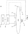
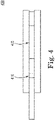
- FIGS. 1 to 4 show a sectional view of a rotary piston pump or rotary vane pump with a pump housing 2.
- the pump chamber 8 is essentially cylindrical.
- a rotary piston is arranged concentrically as a rotor 1 with two vanes 3 lying opposite one another in the circumferential direction.
- the rotor 1 with the blades 3 comprises the rotor axle tube 18 or, in other words, the rotor axle tube 18 and the rotor 1 with the blades 3 form a structural unit.
- an inlet channel (not shown) to at least two inlet openings 6 in the pump chamber 8 and an outlet channel (not shown) to at least two are in the rotor axle tube 18, each extending from the opposite axial ends and separated from one another axially Outlet openings 7 from the pump chamber 8 are present.
- one of the inlet openings 6 is arranged downstream in the direction of rotation 14 and one of the outlet openings 7 is arranged in front of one of the vanes 3 in the rotor axle tube 18 in the direction of rotation 14 .
- a pressure side 7 or outlet side 7 is formed in relation to the direction of rotation 14 in front of the respective wing 3 and a suction side 6 or inlet side 6 is formed after the respective wing 3 in relation to the direction of rotation 14.
- the sealing flap 4b and the omega flap 4b can be understood as synonymous, so that if the sealing flap 4b is mentioned alone, the omega flap 4b is also included.
- the inlet channel (not shown) and the outlet channel (not shown) are separated by means of a channel separation 19, which divides the rotor axle tube 18 into two sections transversely to the axial extent.
- sealing flaps 4a, 4b are distributed opposite one another in the circumferential direction.
- the sealing flaps 4a, 4b have a contour that is curved or in the shape of a circular arc.
- the sealing flaps 4a radial to the pump housing 8 according to FIG. 1 is only slightly curved.
- the sealing flaps 4b shown in Figures 2 to 4 have, as so-called omega flaps 4b, radially to the pump housing 8, a circular arc-shaped or part-cylindrical shell-shaped profile in terms of contour, with the circular arc or the partial cylinder shell being formed over 180 degrees and the respective ends of the Omega flaps 4b have the extension 36 with the inlet or outlet radius 23 corresponding to the pump chamber outer diameter 23 of the housing wall of the pump chamber 2 8 .
- sealing flaps 4a, 4b are each designed to be rotatable or pivotable or rotatable or displaceable.
- the sealing flaps 4a, 4b are rotatably or pivotably mounted in or on the pump housing 2 via spokes 33 or pins 13 at a pivot point 28 or pivot point 28, with the pump housing 2 in the area or range of movement of the two sealing flaps 4a, 4b has at least one free space 29 radially and axially in some areas.
- the radially outer and axial housing wall 2 in the area or area of movement of the two sealing flaps 4a, 4b thus has a widening 29, into which the respective sealing flaps 4a, 4b can at least partially rotate in or rotate through or pivot in, whereby the respective wing 3 can rotate with a maximum radial Length along or past the respective sealing flap 4a, 4b or walk past or the respective sealing flap 4a, 4b can happen.
- the sealing flaps 4a are on the outer edges 4a in the region of the radially outer housing wall 2 of the pump housing 2 and pivoted via, for example, a continuous pin 13 or two individual pins 13 at the radially outer end of the sealing flaps 4a on the pump housing side, so that they can pivot into the free space 29 in the radially outer housing wall 2 .
- the pins 13 are guided or accommodated, for example, in the housing cover 9 , 10 which axially delimits the pump housing 2 or the pump chamber 8 .
- the sealing flaps 4b are designed as omega flaps 4b.
- the omega flaps 4b which are arcuate in contour or have the shape of part of a cylinder jacket, are each guided by means of spokes 33 to a pivot point 28 and are rotatably mounted at this pivot point 28 via a respective pin 13 in the housing cover 9, 10 of the pump housing.
- the omega flaps 4b in the shape of a circular arc or part of a cylinder shell project into a free space 29 or a widening 29 in the pump housing 2 widened for this purpose.
- the housing covers 9, 10 of the pump housing 2 also have the free space 29 or the widening 29, particularly Range of motion of the omega flaps 4b and the spokes 33 on.
- the respective wing 3 is thus able to graze or run past the opening omega flap 4b, while the respective omega flap 4b moves, from the direction of movement opposite to the direction of rotation 14 of the wing 3, around the end of the respective wing 3 moves or rotates without causing a collision.
- the sealing flaps 4a, 4b form pump chamber sections 8a, with the suction side 6 or inlet side 6 being after the sealing flaps 4a, 4b in the direction of rotation 14 and the pressure side 7 or outlet side 7 being in front of the sealing flaps 4a, 4b.
- the rotational speed of the wings 3 in the area or movement area of the sealing flaps 4a, 4b is significantly reduced, which simplifies the synchronization of the respective movements and also avoids collisions.
- the free space 29 or the widening 29 causes the fluid, in particular blood, to be swirled when the sealing flaps 4a, 4b are opened by passing the respective wing 3.
- the pivot point 28 is not arranged centrally but eccentrically in relation to the contour of the arcuate or part-cylindrical omega flap 4b, with the pivot point 28 being chosen such that with Beginning of the rotational movement or opening movement of the sealing flaps 4b or omega flaps 4b, these move away from all contact points 38 or contact points 38 on the circular arc or partial cylinder jacket and thus sealing points 38 to the pump housing 2 and in particular to the housing wall 2, the housing covers 9, 10 and their adjoining areas dissolves and thus already the turbulence and washing around both the flap edges and their inner and outer surfaces, in particular through the free areas 29 or the widening 29 and the free space 37 between the omega flap 4b and the wing 3, are released.
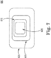
- FIG 7 a section of a detail from Figure 3 shows part of the pump housing 2 with the housing wall 2 and a housing cover 9, the sealing flap 4b as an omega flap 4b with spokes 33 which are guided to a pivot point 28, the rotor axle tube 18 with the rotor 1 and vanes 3 and the rotor axis 20 as the axis of symmetry and an inlet pipe 21 to the housing cover 9 and rotor axle pipe 18 with the inlet channel 11 or the inlet 11 to the rotor axle pipe 18 .
- the omega flap 4b and in the area of the spokes 33 there is a free space 29 or a widening 29 in the pump housing 2 .
- the distance 37 corresponds approximately to the free space 29 or the widening 29 between the respective sealing flap 4b or omega flap 4b and the radial housing wall 2 widened in the region of the respective sealing flap 4b or omega flap 4b or that in this Area of widened axial housing cover 9.
- the wings 3 In order to be able to graze or walk past the wing, as shown in FIGS. 2 to 4, as closely as possible to the contour of the arcuate or partially cylindrical omega flaps 4b, the wings 3 have an S-shaped and thus multiple curved course in the radial direction on. Beneficial are the curves in the radial direction of the contour of the wings 3 and the curved course of the contour of the at least two sealing flaps 4a, 4b similar or adapted to one another, so that as much of the fluid as possible, in particular the blood, can still be conveyed before the sealing flap is opened. This includes the suction side 6 or inflow side 6 and the pressure side 7 or outflow side 7 equally, since the suction 6 and the pressure 7 take place as long as the sealing flap 4b, as the omega flap 4b, is still closed.
- the wings 3 are designed to be radially straight, so that they can brush or run past the sealing flaps 4a without any problems, with this flap solution having a large rotational angle range without conveying, since the sealing flap 4a is already completely closed at the beginning of the incoming wing 3 must be open.
- the blades 3 or rotor 1 are driven, as shown in Figures 1 to 4, by means of magnets 17a on the radial ends of the blades 3 and, as shown in Figure 2, by means of electromagnets 16a on or in the area of the radial housing wall 2 of the pump housing 2 is realized.
- the electromagnets 16a, 16b can be controlled individually and/or as a group, so that depending on the angular position of the vanes 3, different rotational speeds can be set as shown above.
- magnets 17b are also provided on the sealing flaps 4b or omega flaps 4b, with which the position of the sealing flaps 4b or omega flaps 4b can be changed and, if necessary, held or fixed. Accordingly, electromagnets 16b are provided on the pump housing 2 or on the housing covers 9, 10, which can be controlled accordingly, see an example in Figure 2.
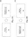
- FIG. 2 different operating states or operating positions of the rotary piston pump or rotary vane pump are shown. While the sealing flaps 4b are closed in FIG. 2 and the wings 3 ensure both suction 6 and pressure 7 at a high rotational speed, in FIG. 3 the sealing flaps 4b are still open after the wings 3 have passed. The speed is still low and can be increased again after the sealing flaps 4b are completely closed.
- FIG. 4 shows that the sealing flaps 4b close again and can follow the suction-side contour of the vanes 3 in order to close immediately after the vanes 3 have rotated slightly further, turning back, so that the new pumping process can begin.
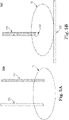
- FIG. 5 shows a sectional view of FIG Omega flap 4b with spokes 33, which are guided to a pivot point 28, is movably arranged.
- the inlet pipe 21 in or on the housing cover 9 is shown as the inlet side, to which the inlet channel 11 in the rotor axle pipe 18 is connected to the inlet opening (not shown) into the pump chamber 8 with a pump chamber depth 25, which corresponds to the length of the rotor axle pipe.
- the outlet opening in the rotor axle tube 18 is not shown, to which the outlet channel 12 in the rotor axle tube 18 and the outlet tube 35 shown below in or on the housing cover 10 are connected.
- flaps 31 are provided in the outlet pipe 35 .
- In the rotor axle tube 18 there is a channel separation 19 which axially separates the inlet channel 11 from the outlet channel 12 running obliquely.
- FIG. 6 shows a sectional view of a rotary piston pump or rotary vane pump at the end of delivery, just before the sealing flaps 4b open. While the vanes 3 are still rotating in the direction of the sealing flaps 4b, for example as omega flaps 4b, which have spokes 33 that are guided to the pivot point 28, flows with flow direction 15 into the pump and pump chamber 8 on the suction side 6 of the vanes 3 and the Sealing flap 4b still contains fluid or blood via the inlet pipe 21, the inlet channel 11 and the inlet opening 6 into the pump chamber 8, while on the pressure side 7 of the vane 3 and the sealing flap 4b with flow direction 15 from the pump still fluid or blood from the pump chamber 8 over the outlet opening 7, the outlet channel 12 and the outlet pipe 35 flows.
- the vanes 3 are still rotating in the direction of the sealing flaps 4b, for example as omega flaps 4b, which have spokes 33 that are guided to the pivot point 28, flows with flow direction 15 into the pump and pump chamber 8 on the suction side 6 of the vanes 3 and the Sealing
- the wings 3 with their magnets are actuated accordingly via the electromagnets 16b and are first decelerated in front of the sealing flaps 4b that are to be opened.
- the sealing flaps 4b with their magnets 17b are controlled by the electromagnets 16b, so that the sealing flaps 4b open in good time and the wings 3 rotate slowly and synchronously with the sealing flaps 4b under them.
- the rotor 1 with the vanes 3 has a rotor bearing 32 in the housing covers 9 , 10 axially delimiting the pump housing 2 at the transition points between the inlet tube 21 and the rotor shaft tube 18 and between the rotor shaft tube 18 and the outlet tube 35 .
- the channel separation 19 is also present in the rotor axle tube 18 .
- a further embodiment of a wing 3 is shown, which counter to the direction of rotation 14 has a crescent-shaped curved course of the contour and at the radial ends in the direction of rotation there are protrusions 22 in the form of a lug or more lugs, which are able to prevent an omega flap 4b that may not be fully in contact with the radially outer housing wall 2 so that the vane 3 can pass freely on the radially outer housing wall 2 to press.
- the approximately tangential extension 36 with the inlet or outlet radius 23 corresponding to the pump chamber outer diameter 23 of the housing wall 2 of the pump chamber 8 or with the pump chamber outer diameter 23 is present on the sealing flap 4b as an omega flap 4b.
- the detail also shows part of the pump housing 2 with the housing wall 2 and the sealing flap 4b as an omega flap 4b with spokes 33 which are guided to a pivot point 28 .
- the channel separation 19 is also present in the rotor axle tube 18 .
- the rotor 1 with the vanes 3 has a rotor bearing 32 in the housing covers 9, 10, which axially delimit the pump housing 2, at the transition points between the inlet tube 21 and the rotor shaft tube 18 and between the rotor shaft tube 18 and the outlet tube 35, as shown in the side view in Figure 8 .
- FIGS. 9 and 10 each show a combined arrangement of two rotary piston pumps or rotary vane pumps.
- each of the pumps has its own drive for the rotor 1 or the vanes 3.
- the rotor bearing 32 of the rotor axle 20 is present in the inlet pipe 21 of the pump shown above and in the outlet pipe 35 of the pump shown below and between the pumps in the transition between the outlet pipe 35 of the pump shown above and the inlet pipe 21 of the pump shown below.
- the expansion 29 in the form of a channel in the housing covers 9, 10 is in the form of a circular arc only shortly before the sealing contact between the pump housing 2 and sealing flap 4b present.
- the sealing flap 4b seals on the rotor axle tube 18 and on the housing covers 9, 10 away from the widening 29 and on the radially outer housing wall 2, as shown in the upper half of FIG.
Landscapes
- Health & Medical Sciences (AREA)
- Engineering & Computer Science (AREA)
- Heart & Thoracic Surgery (AREA)
- Mechanical Engineering (AREA)
- Cardiology (AREA)
- Biomedical Technology (AREA)
- Anesthesiology (AREA)
- Hematology (AREA)
- Life Sciences & Earth Sciences (AREA)
- Animal Behavior & Ethology (AREA)
- General Health & Medical Sciences (AREA)
- Public Health (AREA)
- Veterinary Medicine (AREA)
- General Engineering & Computer Science (AREA)
- External Artificial Organs (AREA)
Applications Claiming Priority (1)
| Application Number | Priority Date | Filing Date | Title |
|---|---|---|---|
| DE102020132226 | 2020-12-03 |
Publications (4)
| Publication Number | Publication Date |
|---|---|
| EP4008904A1 true EP4008904A1 (fr) | 2022-06-08 |
| EP4008904A9 EP4008904A9 (fr) | 2023-04-19 |
| EP4008904C0 EP4008904C0 (fr) | 2024-12-25 |
| EP4008904B1 EP4008904B1 (fr) | 2024-12-25 |
Family
ID=81393218
Family Applications (1)
| Application Number | Title | Priority Date | Filing Date |
|---|---|---|---|
| EP21212330.1A Active EP4008904B1 (fr) | 2020-12-03 | 2021-12-03 | Pompe d'assistance cardiaque |
Country Status (3)
| Country | Link |
|---|---|
| US (1) | US12151093B2 (fr) |
| EP (1) | EP4008904B1 (fr) |
| DE (1) | DE102021131924A1 (fr) |
Citations (5)
| Publication number | Priority date | Publication date | Assignee | Title |
|---|---|---|---|---|
| DE6927594U (de) | 1969-07-12 | 1971-08-12 | Braunschweigische Maschb Nstal | Drehkolbenpumpe. |
| US6576010B2 (en) * | 2000-07-20 | 2003-06-10 | Izaak A. Ulert | Circular artificial heart |
| DE102004005468B4 (de) | 2004-02-03 | 2013-11-21 | Franz-Harro Horn | Rotationskolbenmaschine |
| DE202016000016U1 (de) | 2016-01-04 | 2016-01-25 | Heinz Prümer | Drehkolbenpumpe |
| US20190167872A1 (en) * | 2016-04-12 | 2019-06-06 | Centre Hospitalier Universitaire Vaudois | Artificial heart and its drive unit |
Family Cites Families (2)
| Publication number | Priority date | Publication date | Assignee | Title |
|---|---|---|---|---|
| US2501947A (en) * | 1944-05-17 | 1950-03-28 | James P Johnson | Hydraulic pump |
| DE102014010745A1 (de) * | 2014-07-23 | 2016-02-11 | Rheinisch-Westfälische Technische Hochschule Aachen | Rotationskolbenpumpe |
-
2021
- 2021-12-03 EP EP21212330.1A patent/EP4008904B1/fr active Active
- 2021-12-03 DE DE102021131924.2A patent/DE102021131924A1/de active Pending
- 2021-12-03 US US17/541,302 patent/US12151093B2/en active Active
Patent Citations (5)
| Publication number | Priority date | Publication date | Assignee | Title |
|---|---|---|---|---|
| DE6927594U (de) | 1969-07-12 | 1971-08-12 | Braunschweigische Maschb Nstal | Drehkolbenpumpe. |
| US6576010B2 (en) * | 2000-07-20 | 2003-06-10 | Izaak A. Ulert | Circular artificial heart |
| DE102004005468B4 (de) | 2004-02-03 | 2013-11-21 | Franz-Harro Horn | Rotationskolbenmaschine |
| DE202016000016U1 (de) | 2016-01-04 | 2016-01-25 | Heinz Prümer | Drehkolbenpumpe |
| US20190167872A1 (en) * | 2016-04-12 | 2019-06-06 | Centre Hospitalier Universitaire Vaudois | Artificial heart and its drive unit |
Also Published As
| Publication number | Publication date |
|---|---|
| DE102021131924A1 (de) | 2022-06-09 |
| EP4008904C0 (fr) | 2024-12-25 |
| EP4008904B1 (fr) | 2024-12-25 |
| US20220176099A1 (en) | 2022-06-09 |
| EP4008904A9 (fr) | 2023-04-19 |
| US12151093B2 (en) | 2024-11-26 |
Similar Documents
| Publication | Publication Date | Title |
|---|---|---|
| DE19535781C2 (de) | Vorrichtung zur aktiven Strömungsunterstützung von Körperflüssigkeiten | |
| EP1261385B1 (fr) | Pompe a sang | |
| DE69027029T2 (de) | Herzunterstützungspumpe | |
| DE60301135T2 (de) | Blutpumpe mit axialem und radialem durchfluss und mit doppeltem eingang | |
| DE69931960T2 (de) | Blutpumpe unter anwendung des querströmungsprinzips | |
| EP3010562B1 (fr) | Système d'assistance cardiaque | |
| DE3280454T2 (de) | Magnetisch gelagerter und angetriebener Kreiselpumpenapparat. | |
| DE69732557T2 (de) | Rotationsblutpumpe | |
| US11324941B2 (en) | Intraventricular pulsating blood pump | |
| WO2011131766A1 (fr) | Dispositif d'assistance cardiaque | |
| CH617495A5 (fr) | ||
| DE19903341A1 (de) | Einkammer-Blutpumpe | |
| DE2819851A1 (de) | Kuenstliches herz | |
| EP2523702A1 (fr) | Agencement comportant une pompe à sang et un échangeur gazeux pour l'oxygénation de membrane extracorporelle | |
| EP1374928B1 (fr) | Pompe à sang à turbine | |
| EP2046414B1 (fr) | Système à deux chambres implantable destiné à supporter le ventricule gauche du coeur | |
| DE68907576T2 (de) | Verdrängerpumpe. | |
| EP4008904B1 (fr) | Pompe d'assistance cardiaque | |
| WO1983000725A1 (fr) | Pompe centrifuge hermetique pour le pompage avec menagement de fluides | |
| DE3610255A1 (de) | Blut-retroperfusionssystem | |
| DE102020132268B3 (de) | Künstliches herz | |
| DE60031781T2 (de) | Blutpump vorrichtung für einen extrakorporalen kreislauf und zur herzunterstützung | |
| EP4427796A1 (fr) | Système comprenant une pompe à sang et une unité de commande et procédé de fonctionnement d'une pompe à sang | |
| DE2361023A1 (de) | Herzpumpe | |
| DE202015001252U1 (de) | Kunstherz |
Legal Events
| Date | Code | Title | Description |
|---|---|---|---|
| STAA | Information on the status of an ep patent application or granted ep patent |
Free format text: STATUS: UNKNOWN |
|
| PUAI | Public reference made under article 153(3) epc to a published international application that has entered the european phase |
Free format text: ORIGINAL CODE: 0009012 |
|
| STAA | Information on the status of an ep patent application or granted ep patent |
Free format text: STATUS: THE APPLICATION HAS BEEN PUBLISHED |
|
| AK | Designated contracting states |
Kind code of ref document: A1 Designated state(s): AL AT BE BG CH CY CZ DE DK EE ES FI FR GB GR HR HU IE IS IT LI LT LU LV MC MK MT NL NO PL PT RO RS SE SI SK SM TR |
|
| STAA | Information on the status of an ep patent application or granted ep patent |
Free format text: STATUS: REQUEST FOR EXAMINATION WAS MADE |
|
| 17P | Request for examination filed |
Effective date: 20221125 |
|
| RBV | Designated contracting states (corrected) |
Designated state(s): AL AT BE BG CH CY CZ DE DK EE ES FI FR GB GR HR HU IE IS IT LI LT LU LV MC MK MT NL NO PL PT RO RS SE SI SK SM TR |
|
| RAP1 | Party data changed (applicant data changed or rights of an application transferred) |
Owner name: RAP-P MEDITEC UG |
|
| RIN1 | Information on inventor provided before grant (corrected) |
Inventor name: HORN, FRANZ-HARRO |
|
| GRAP | Despatch of communication of intention to grant a patent |
Free format text: ORIGINAL CODE: EPIDOSNIGR1 |
|
| STAA | Information on the status of an ep patent application or granted ep patent |
Free format text: STATUS: GRANT OF PATENT IS INTENDED |
|
| RIC1 | Information provided on ipc code assigned before grant |
Ipc: A61M 60/258 20210101ALI20240802BHEP Ipc: A61M 60/896 20210101ALI20240802BHEP Ipc: A61M 60/894 20210101ALI20240802BHEP Ipc: A61M 60/835 20210101ALI20240802BHEP Ipc: A61M 60/441 20210101ALI20240802BHEP Ipc: A61M 60/196 20210101ALI20240802BHEP Ipc: F04C 15/06 20060101ALI20240802BHEP Ipc: F04C 13/00 20060101ALI20240802BHEP Ipc: F04C 2/22 20060101AFI20240802BHEP |
|
| INTG | Intention to grant announced |
Effective date: 20240902 |
|
| GRAS | Grant fee paid |
Free format text: ORIGINAL CODE: EPIDOSNIGR3 |
|
| GRAA | (expected) grant |
Free format text: ORIGINAL CODE: 0009210 |
|
| STAA | Information on the status of an ep patent application or granted ep patent |
Free format text: STATUS: THE PATENT HAS BEEN GRANTED |
|
| AK | Designated contracting states |
Kind code of ref document: B1 Designated state(s): AL AT BE BG CH CY CZ DE DK EE ES FI FR GB GR HR HU IE IS IT LI LT LU LV MC MK MT NL NO PL PT RO RS SE SI SK SM TR |
|
| REG | Reference to a national code |
Ref country code: GB Ref legal event code: FG4D Free format text: NOT ENGLISH |
|
| REG | Reference to a national code |
Ref country code: CH Ref legal event code: EP |
|
| REG | Reference to a national code |
Ref country code: DE Ref legal event code: R096 Ref document number: 502021006200 Country of ref document: DE |
|
| REG | Reference to a national code |
Ref country code: IE Ref legal event code: FG4D Free format text: LANGUAGE OF EP DOCUMENT: GERMAN |
|
| U01 | Request for unitary effect filed |
Effective date: 20250110 |
|
| U07 | Unitary effect registered |
Designated state(s): AT BE BG DE DK EE FI FR IT LT LU LV MT NL PT RO SE SI Effective date: 20250117 |
|
| PG25 | Lapsed in a contracting state [announced via postgrant information from national office to epo] |
Ref country code: HR Free format text: LAPSE BECAUSE OF FAILURE TO SUBMIT A TRANSLATION OF THE DESCRIPTION OR TO PAY THE FEE WITHIN THE PRESCRIBED TIME-LIMIT Effective date: 20241225 |
|
| PG25 | Lapsed in a contracting state [announced via postgrant information from national office to epo] |
Ref country code: NO Free format text: LAPSE BECAUSE OF FAILURE TO SUBMIT A TRANSLATION OF THE DESCRIPTION OR TO PAY THE FEE WITHIN THE PRESCRIBED TIME-LIMIT Effective date: 20250325 |
|
| PG25 | Lapsed in a contracting state [announced via postgrant information from national office to epo] |
Ref country code: GR Free format text: LAPSE BECAUSE OF FAILURE TO SUBMIT A TRANSLATION OF THE DESCRIPTION OR TO PAY THE FEE WITHIN THE PRESCRIBED TIME-LIMIT Effective date: 20250326 |
|
| PG25 | Lapsed in a contracting state [announced via postgrant information from national office to epo] |
Ref country code: RS Free format text: LAPSE BECAUSE OF FAILURE TO SUBMIT A TRANSLATION OF THE DESCRIPTION OR TO PAY THE FEE WITHIN THE PRESCRIBED TIME-LIMIT Effective date: 20250325 |
|
| U1N | Appointed representative for the unitary patent procedure changed after the registration of the unitary effect |
Representative=s name: SCHIED, SEBASTIAN; DE |
|
| PG25 | Lapsed in a contracting state [announced via postgrant information from national office to epo] |
Ref country code: SM Free format text: LAPSE BECAUSE OF FAILURE TO SUBMIT A TRANSLATION OF THE DESCRIPTION OR TO PAY THE FEE WITHIN THE PRESCRIBED TIME-LIMIT Effective date: 20241225 |
|
| PG25 | Lapsed in a contracting state [announced via postgrant information from national office to epo] |
Ref country code: PL Free format text: LAPSE BECAUSE OF FAILURE TO SUBMIT A TRANSLATION OF THE DESCRIPTION OR TO PAY THE FEE WITHIN THE PRESCRIBED TIME-LIMIT Effective date: 20241225 |
|
| PG25 | Lapsed in a contracting state [announced via postgrant information from national office to epo] |
Ref country code: ES Free format text: LAPSE BECAUSE OF FAILURE TO SUBMIT A TRANSLATION OF THE DESCRIPTION OR TO PAY THE FEE WITHIN THE PRESCRIBED TIME-LIMIT Effective date: 20241225 |
|
| PG25 | Lapsed in a contracting state [announced via postgrant information from national office to epo] |
Ref country code: IS Free format text: LAPSE BECAUSE OF FAILURE TO SUBMIT A TRANSLATION OF THE DESCRIPTION OR TO PAY THE FEE WITHIN THE PRESCRIBED TIME-LIMIT Effective date: 20250425 |
|
| PG25 | Lapsed in a contracting state [announced via postgrant information from national office to epo] |
Ref country code: SK Free format text: LAPSE BECAUSE OF FAILURE TO SUBMIT A TRANSLATION OF THE DESCRIPTION OR TO PAY THE FEE WITHIN THE PRESCRIBED TIME-LIMIT Effective date: 20241225 |
|
| PG25 | Lapsed in a contracting state [announced via postgrant information from national office to epo] |
Ref country code: CZ Free format text: LAPSE BECAUSE OF FAILURE TO SUBMIT A TRANSLATION OF THE DESCRIPTION OR TO PAY THE FEE WITHIN THE PRESCRIBED TIME-LIMIT Effective date: 20241225 |
|
| PLBE | No opposition filed within time limit |
Free format text: ORIGINAL CODE: 0009261 |
|
| STAA | Information on the status of an ep patent application or granted ep patent |
Free format text: STATUS: NO OPPOSITION FILED WITHIN TIME LIMIT |
|
| 26N | No opposition filed |
Effective date: 20250926 |
|
| U20 | Renewal fee for the european patent with unitary effect paid |
Year of fee payment: 5 Effective date: 20251222 |