EP4008904B1 - Pompe d'assistance cardiaque - Google Patents
Pompe d'assistance cardiaque Download PDFInfo
- Publication number
- EP4008904B1 EP4008904B1 EP21212330.1A EP21212330A EP4008904B1 EP 4008904 B1 EP4008904 B1 EP 4008904B1 EP 21212330 A EP21212330 A EP 21212330A EP 4008904 B1 EP4008904 B1 EP 4008904B1
- Authority
- EP
- European Patent Office
- Prior art keywords
- pump
- rotor
- sealing
- rotary piston
- flap
- Prior art date
- Legal status (The legal status is an assumption and is not a legal conclusion. Google has not performed a legal analysis and makes no representation as to the accuracy of the status listed.)
- Active
Links
Images


Classifications
-
- A—HUMAN NECESSITIES
- A61—MEDICAL OR VETERINARY SCIENCE; HYGIENE
- A61M—DEVICES FOR INTRODUCING MEDIA INTO, OR ONTO, THE BODY; DEVICES FOR TRANSDUCING BODY MEDIA OR FOR TAKING MEDIA FROM THE BODY; DEVICES FOR PRODUCING OR ENDING SLEEP OR STUPOR
- A61M60/00—Blood pumps; Devices for mechanical circulatory actuation; Balloon pumps for circulatory assistance
- A61M60/80—Constructional details other than related to driving
- A61M60/802—Constructional details other than related to driving of non-positive displacement blood pumps
- A61M60/81—Pump housings
- A61M60/812—Vanes or blades, e.g. static flow guides
-
- F—MECHANICAL ENGINEERING; LIGHTING; HEATING; WEAPONS; BLASTING
- F04—POSITIVE - DISPLACEMENT MACHINES FOR LIQUIDS; PUMPS FOR LIQUIDS OR ELASTIC FLUIDS
- F04C—ROTARY-PISTON, OR OSCILLATING-PISTON, POSITIVE-DISPLACEMENT MACHINES FOR LIQUIDS; ROTARY-PISTON, OR OSCILLATING-PISTON, POSITIVE-DISPLACEMENT PUMPS
- F04C2/00—Rotary-piston machines or pumps
- F04C2/22—Rotary-piston machines or pumps of internal-axis type with equidirectional movement of co-operating members at the points of engagement, or with one of the co-operating members being stationary, the inner member having more teeth or tooth-equivalents than the outer member
-
- A—HUMAN NECESSITIES
- A61—MEDICAL OR VETERINARY SCIENCE; HYGIENE
- A61M—DEVICES FOR INTRODUCING MEDIA INTO, OR ONTO, THE BODY; DEVICES FOR TRANSDUCING BODY MEDIA OR FOR TAKING MEDIA FROM THE BODY; DEVICES FOR PRODUCING OR ENDING SLEEP OR STUPOR
- A61M60/00—Blood pumps; Devices for mechanical circulatory actuation; Balloon pumps for circulatory assistance
- A61M60/10—Location thereof with respect to the patient's body
- A61M60/122—Implantable pumps or pumping devices, i.e. the blood being pumped inside the patient's body
- A61M60/196—Implantable pumps or pumping devices, i.e. the blood being pumped inside the patient's body replacing the entire heart, e.g. total artificial hearts [TAH]
-
- A—HUMAN NECESSITIES
- A61—MEDICAL OR VETERINARY SCIENCE; HYGIENE
- A61M—DEVICES FOR INTRODUCING MEDIA INTO, OR ONTO, THE BODY; DEVICES FOR TRANSDUCING BODY MEDIA OR FOR TAKING MEDIA FROM THE BODY; DEVICES FOR PRODUCING OR ENDING SLEEP OR STUPOR
- A61M60/00—Blood pumps; Devices for mechanical circulatory actuation; Balloon pumps for circulatory assistance
- A61M60/20—Type thereof
- A61M60/205—Non-positive displacement blood pumps
- A61M60/216—Non-positive displacement blood pumps including a rotating member acting on the blood, e.g. impeller
- A61M60/221—Non-positive displacement blood pumps including a rotating member acting on the blood, e.g. impeller the blood flow through the rotating member having both radial and axial components, e.g. mixed flow pumps
-
- A—HUMAN NECESSITIES
- A61—MEDICAL OR VETERINARY SCIENCE; HYGIENE
- A61M—DEVICES FOR INTRODUCING MEDIA INTO, OR ONTO, THE BODY; DEVICES FOR TRANSDUCING BODY MEDIA OR FOR TAKING MEDIA FROM THE BODY; DEVICES FOR PRODUCING OR ENDING SLEEP OR STUPOR
- A61M60/00—Blood pumps; Devices for mechanical circulatory actuation; Balloon pumps for circulatory assistance
- A61M60/20—Type thereof
- A61M60/247—Positive displacement blood pumps
- A61M60/253—Positive displacement blood pumps including a displacement member directly acting on the blood
- A61M60/258—Piston pumps
-
- A—HUMAN NECESSITIES
- A61—MEDICAL OR VETERINARY SCIENCE; HYGIENE
- A61M—DEVICES FOR INTRODUCING MEDIA INTO, OR ONTO, THE BODY; DEVICES FOR TRANSDUCING BODY MEDIA OR FOR TAKING MEDIA FROM THE BODY; DEVICES FOR PRODUCING OR ENDING SLEEP OR STUPOR
- A61M60/00—Blood pumps; Devices for mechanical circulatory actuation; Balloon pumps for circulatory assistance
- A61M60/40—Details relating to driving
- A61M60/403—Details relating to driving for non-positive displacement blood pumps
- A61M60/422—Details relating to driving for non-positive displacement blood pumps the force acting on the blood contacting member being electromagnetic, e.g. using canned motor pumps
-
- A—HUMAN NECESSITIES
- A61—MEDICAL OR VETERINARY SCIENCE; HYGIENE
- A61M—DEVICES FOR INTRODUCING MEDIA INTO, OR ONTO, THE BODY; DEVICES FOR TRANSDUCING BODY MEDIA OR FOR TAKING MEDIA FROM THE BODY; DEVICES FOR PRODUCING OR ENDING SLEEP OR STUPOR
- A61M60/00—Blood pumps; Devices for mechanical circulatory actuation; Balloon pumps for circulatory assistance
- A61M60/40—Details relating to driving
- A61M60/424—Details relating to driving for positive displacement blood pumps
- A61M60/438—Details relating to driving for positive displacement blood pumps the force acting on the blood contacting member being mechanical
- A61M60/441—Details relating to driving for positive displacement blood pumps the force acting on the blood contacting member being mechanical generated by an electromotor
-
- A—HUMAN NECESSITIES
- A61—MEDICAL OR VETERINARY SCIENCE; HYGIENE
- A61M—DEVICES FOR INTRODUCING MEDIA INTO, OR ONTO, THE BODY; DEVICES FOR TRANSDUCING BODY MEDIA OR FOR TAKING MEDIA FROM THE BODY; DEVICES FOR PRODUCING OR ENDING SLEEP OR STUPOR
- A61M60/00—Blood pumps; Devices for mechanical circulatory actuation; Balloon pumps for circulatory assistance
- A61M60/50—Details relating to control
- A61M60/508—Electronic control means, e.g. for feedback regulation
- A61M60/538—Regulation using real-time blood pump operational parameter data, e.g. motor current
-
- A—HUMAN NECESSITIES
- A61—MEDICAL OR VETERINARY SCIENCE; HYGIENE
- A61M—DEVICES FOR INTRODUCING MEDIA INTO, OR ONTO, THE BODY; DEVICES FOR TRANSDUCING BODY MEDIA OR FOR TAKING MEDIA FROM THE BODY; DEVICES FOR PRODUCING OR ENDING SLEEP OR STUPOR
- A61M60/00—Blood pumps; Devices for mechanical circulatory actuation; Balloon pumps for circulatory assistance
- A61M60/80—Constructional details other than related to driving
- A61M60/802—Constructional details other than related to driving of non-positive displacement blood pumps
- A61M60/81—Pump housings
- A61M60/816—Sensors arranged on or in the housing, e.g. ultrasonic flow sensors
-
- A—HUMAN NECESSITIES
- A61—MEDICAL OR VETERINARY SCIENCE; HYGIENE
- A61M—DEVICES FOR INTRODUCING MEDIA INTO, OR ONTO, THE BODY; DEVICES FOR TRANSDUCING BODY MEDIA OR FOR TAKING MEDIA FROM THE BODY; DEVICES FOR PRODUCING OR ENDING SLEEP OR STUPOR
- A61M60/00—Blood pumps; Devices for mechanical circulatory actuation; Balloon pumps for circulatory assistance
- A61M60/80—Constructional details other than related to driving
- A61M60/835—Constructional details other than related to driving of positive displacement blood pumps
-
- A—HUMAN NECESSITIES
- A61—MEDICAL OR VETERINARY SCIENCE; HYGIENE
- A61M—DEVICES FOR INTRODUCING MEDIA INTO, OR ONTO, THE BODY; DEVICES FOR TRANSDUCING BODY MEDIA OR FOR TAKING MEDIA FROM THE BODY; DEVICES FOR PRODUCING OR ENDING SLEEP OR STUPOR
- A61M60/00—Blood pumps; Devices for mechanical circulatory actuation; Balloon pumps for circulatory assistance
- A61M60/80—Constructional details other than related to driving
- A61M60/855—Constructional details other than related to driving of implantable pumps or pumping devices
- A61M60/89—Valves
- A61M60/894—Passive valves, i.e. valves actuated by the blood
- A61M60/896—Passive valves, i.e. valves actuated by the blood having flexible or resilient parts, e.g. flap valves
-
- F—MECHANICAL ENGINEERING; LIGHTING; HEATING; WEAPONS; BLASTING
- F04—POSITIVE - DISPLACEMENT MACHINES FOR LIQUIDS; PUMPS FOR LIQUIDS OR ELASTIC FLUIDS
- F04C—ROTARY-PISTON, OR OSCILLATING-PISTON, POSITIVE-DISPLACEMENT MACHINES FOR LIQUIDS; ROTARY-PISTON, OR OSCILLATING-PISTON, POSITIVE-DISPLACEMENT PUMPS
- F04C13/00—Adaptations of machines or pumps for special use, e.g. for extremely high pressures
- F04C13/001—Pumps for particular liquids
-
- F—MECHANICAL ENGINEERING; LIGHTING; HEATING; WEAPONS; BLASTING
- F04—POSITIVE - DISPLACEMENT MACHINES FOR LIQUIDS; PUMPS FOR LIQUIDS OR ELASTIC FLUIDS
- F04C—ROTARY-PISTON, OR OSCILLATING-PISTON, POSITIVE-DISPLACEMENT MACHINES FOR LIQUIDS; ROTARY-PISTON, OR OSCILLATING-PISTON, POSITIVE-DISPLACEMENT PUMPS
- F04C15/00—Component parts, details or accessories of machines, pumps or pumping installations, not provided for in groups F04C2/00 - F04C14/00
- F04C15/06—Arrangements for admission or discharge of the working fluid, e.g. constructional features of the inlet or outlet
- F04C15/064—Arrangements for admission or discharge of the working fluid, e.g. constructional features of the inlet or outlet with inlet and outlet valves specially adapted for rotary or oscillating piston machines or pumps
-
- A—HUMAN NECESSITIES
- A61—MEDICAL OR VETERINARY SCIENCE; HYGIENE
- A61M—DEVICES FOR INTRODUCING MEDIA INTO, OR ONTO, THE BODY; DEVICES FOR TRANSDUCING BODY MEDIA OR FOR TAKING MEDIA FROM THE BODY; DEVICES FOR PRODUCING OR ENDING SLEEP OR STUPOR
- A61M2205/00—General characteristics of the apparatus
- A61M2205/10—General characteristics of the apparatus with powered movement mechanisms
- A61M2205/103—General characteristics of the apparatus with powered movement mechanisms rotating
-
- A—HUMAN NECESSITIES
- A61—MEDICAL OR VETERINARY SCIENCE; HYGIENE
- A61M—DEVICES FOR INTRODUCING MEDIA INTO, OR ONTO, THE BODY; DEVICES FOR TRANSDUCING BODY MEDIA OR FOR TAKING MEDIA FROM THE BODY; DEVICES FOR PRODUCING OR ENDING SLEEP OR STUPOR
- A61M2205/00—General characteristics of the apparatus
- A61M2205/33—Controlling, regulating or measuring
- A61M2205/3317—Electromagnetic, inductive or dielectric measuring means
-
- F—MECHANICAL ENGINEERING; LIGHTING; HEATING; WEAPONS; BLASTING
- F04—POSITIVE - DISPLACEMENT MACHINES FOR LIQUIDS; PUMPS FOR LIQUIDS OR ELASTIC FLUIDS
- F04C—ROTARY-PISTON, OR OSCILLATING-PISTON, POSITIVE-DISPLACEMENT MACHINES FOR LIQUIDS; ROTARY-PISTON, OR OSCILLATING-PISTON, POSITIVE-DISPLACEMENT PUMPS
- F04C2210/00—Fluid
- F04C2210/10—Fluid working
- F04C2210/1016—Blood
Definitions
- the invention relates to a pump for cardiac support.
- the pump is intended to simulate a pulse beat and support blood flow very gently.
- Rotary piston pumps with two intermeshed rotary pistons or one rotary piston and a sealing flap are known from hydraulic pump construction.
- Vane pumps are also known, which have an alternating rotary-pivoting movement of a vane with valve flaps in the vane and in the pump housing for the inlet and outlet.
- the problem with the known pumps is that dead spaces with no flow can form, so that when used as a blood pump there is a risk of blood clots and/or plaque forming.
- the US 2019/167872 A1 discloses an artificial heart with a pump, the pump comprising a housing with a substantially spherical cavity and four vascular ports.
- a rotatable disc is mounted in the housing and secured to rotate about a fixed axis, while two oscillating pallets are mounted to rotate about a movable axis movable in a plane perpendicular to the fixed axis, the pallets being interconnected and arranged diametrically opposite each other on either side of the rotatable disc (11) to form two pumping units each comprising two variable-sized chambers in fluid communication with a vascular port.
- an oscillating movement of each oscillating pallet relative to the rotatable disc occurs to simultaneously produce two suction strokes and two discharge strokes so as to pump blood into one chamber of each pumping unit and blood out of the other chamber of each pumping unit through the corresponding vascular ports.
- the drive unit of the pump generates a rotating magnetic field within the pump housing.
- the object of the invention is to create a rotary piston pump or rotary vane pump which is membrane-free and is able to adjust a pulse during pumping. This is intended to achieve a gentle pumping of the respective fluid, for example blood.
- the rotary piston pump or rotary vane pump according to the invention is able to simulate a pulse during its pumping work.
- the special basic conditions of a device that replaces a human heart can be taken into account.
- the invention achieves the creation of a rotary piston pump or rotary vane pump, comprising a pump housing with a substantially cylindrical pump chamber and a rotary piston as a rotor with at least two vanes arranged opposite one another or evenly distributed in the circumferential direction, a rotor shaft tube and at least one sealing flap, wherein there are at least two sealing flaps arranged opposite one another or evenly distributed in the circumferential direction, and wherein the at least two sealing flaps are rotatable or pivotable, and wherein in the rotor shaft tube there is an inlet channel extending from the opposite axial ends and axially separated from one another to at least two inlet openings in the pump chamber and an outlet channel axially from at least two outlet openings from the pump chamber, wherein one of the inlet openings is arranged after one of the vanes in the direction of rotation and one of the outlet openings is arranged in front of one of the vanes in the direction of rotation in the rotor shaft tube.
- Rotatable or pivotable also includes dis
- a pressure side or discharge side or a corresponding area is formed in front of the respective blade and, in the direction of rotation, a suction side or inlet side or a corresponding area is formed behind the respective blade.
- the invention further comprises a method for operating a rotary piston pump or rotary vane pump, in which in a substantially cylindrical pump chamber of a pump housing, by the rotary movement of a rotary piston as a rotor with a rotor shaft tube and with at least two vanes arranged opposite one another or evenly distributed in the circumferential direction, a fluid is pressed into an outlet opening in the rotor shaft tube in the direction of rotation in front of the respective vane and at the same time the fluid is sucked in through an inlet opening in the rotor shaft tube in the direction of rotation after the respective vane, wherein a separation of the areas of pressing and suction is carried out by means of a sealing flap and the respective sealing flap is in a closed position for the pressure or discharge and the suction or inflow and after the pressure or discharge and the suction or inflow for passing the respective vane, the respective sealing flap is connected to the radially outer area of the pump chamber is pivoted or rotated around the radially outer end of the respective wing and after passing the respective
- a rotor with at least two blades is arranged in the essentially cylindrical pump chamber of the pump housing, for example with a front and rear housing cover, which rotor moves blood by means of its rotation.
- the fluid is moved largely only in a laminar manner, partially deliberately accelerated and also pressed and accelerated in the pump during pumping, similar to the natural heart.
- the rotor pumps the blood through a rotary movement over a range of approx. 140° angle of rotation per pulse within half a revolution or within 180° angle of rotation in only approx. 0.24 seconds.
- Half a revolution corresponds to a pulse, corresponding to 70 pulses on average per minute.
- this type of pump transfers this to the medium to be pumped through its moderate rotation, which is of great importance for the anatomy of blood movement and thus helps to prevent thrombi and plaque formation.
- the outlet channel or the rotor axis tube for the outlet or the output pipe has a winding or helical course or internal cross-section.
- the fluid describes its flow through clearly defined guide cross-sections without sharp edges etc.
- the blood cannot be significantly damaged.
- the movements of the components are comparatively calm movements of very smooth surfaces in the blood medium, which at this point are deliberately intended to freely wash around the flap and the wing in all directions and to flush them.
- the rotary piston pump or rotary vane pump according to the invention has at least two sealing flaps. Due to the interruption of the delivery capacity by the sealing flap described above, which opens to allow the vane to pass, but otherwise represents the temporal and/or spatial limitation of the pump chamber with the pump chamber sections, a timing or pulsation of the fluid as the material being pumped results.
- a pulsating blood pump i.e. as a partial or one-sided heart support or even as a complete heart replacement and thus works for both heart chambers.
- the vascular system is stretched and completely relieved by the pulse emanating from the pump, similar to the work of the natural heart. This keeps not only the vascular system but also the ventricular system pulsating and elastic.
- the rotor axle tube is axially divided into two sections, wherein a flow-optimized, for example oblique, also rounded or curved channel separation is provided transversely to the axial extension of the rotor axle tube, and thus the inlet channel forms an inflow channel from one axial end into the rotor axle tube and the outlet channel forms an outflow channel from the opposite axial end of the rotor axle tube, wherein the fluid enters the pump chamber through the inlet channel as an inflow channel via the inlet openings and the fluid leaves the pump chamber through the Outlet openings in the outlet channel as an outflow channel.
- a flow-optimized, for example oblique, also rounded or curved channel separation is provided transversely to the axial extension of the rotor axle tube, and thus the inlet channel forms an inflow channel from one axial end into the rotor axle tube and the outlet channel forms an outflow channel from the opposite axial end of the rotor axle tube, wherein the fluid enters the pump chamber through the inlet channel
- the rotary piston pump or rotary vane pump according to the invention provides support for the human heart or allows a heart to be partially replaced with an artificial replacement.
- the rotary piston pump according to the invention provides a basic pulse rate similar to that of a healthy heart, for example close to 70 pulses/min, by using a drive to electronically pump a delivery volume determined or designed for the patient, for example approx. 70 cm 3 per revolution and thus for example 4,900 cm 3 /min of blood.
- the fresh blood supply can be adapted to the respective body and also pulsated into the bloodstream in a variable manner.
- the simple construction comprises three moving rotating or partially rotating parts, comprising the rotor with vanes and the two sealing flaps, and a substantially circular cylindrical pump housing made of metallic or other non-aging materials.
- the rotary piston pump or rotary vane pump according to the invention makes it possible to provide a basic pulse rate similar to that of a healthy heart in normal pulse mode with approximately 70 pulses per minute, but also with a significantly increased or reduced flow rate, adjusted by the speed.
- the active delivery of blood from the rotary piston pump or rotary vane pump directly follows the command from the sinus node, which is transferred digitally to the control unit and passed on as an electrical command.
- the delivery rate can be adjusted for both small and large hearts as well as for larger or smaller delivery volumes by adjusting the size of the pump chamber in terms of length or diameter to the desired delivery volume of the specific patient, thus making different performance sizes easily scalable for use.
- the speed of the pump can also be adjusted based on the oxygen demand to be measured or other physiological parameters so that the pulse is similar to that of a human heart is able to adapt both temporarily and permanently when there is increased effort or performance requirement, provided that this physiological information can be made available by measurement and, for example, a higher speed is specified for the drive, for example the rotating field of an electric motor, using software and hardware.
- a simple rotor bearing is provided if the rotor, for example, has two blades in relation to one revolution or the full circle at 0° and at 180° and thus the desired delivery volume can be pumped or moved per half revolution and the arrangement of the blades of the rotor divides the pump chamber into two delivery halves, for example, so that two separate delivery areas each provide the predetermined volume over half a revolution and the rotor axis tube has a channel separation in the middle of the axial extension.
- the rotor shaft tube of the rotor can be mounted in the pump housing, for example on two housing halves or on two housing covers on a housing or on a concentrically arranged centering or guide axis or shaft or in another suitable manner.
- the rotor shaft tube can run on the surface of the respective housing component or be mounted in a recess or can protrude into corresponding openings of the inlet or outlet and be mounted there.
- the vanes form a first and a second pumping area, each covering an area of half a revolution of the rotor.
- the volume is, for example, twice approximately 35 cm3 per half revolution, so that 70 cm3 can be pumped per pulse.
- magnets may be fitted on the vanes and electromagnets may be fitted on the pump housing on the housing wall and/or the housing covers, for example on the two housing surfaces present in the axial direction, running around the circumference. present.
- the rotor can also be centered purely by electromagnetic-electronic measurement, by controlling the corresponding action by increasing or decreasing the load on the electromagnets.
- varying rotation speeds of the rotor can also be achieved depending on the increasing or decreasing amount of blood required.
- the pump housing can be constructed in several parts.
- the pump housing can be formed or assembled in several parts using two housing halves or with two housing covers on one housing or in another way.
- a sealing rotor can be dispensed with, which means that the size of the artificial heart can be significantly reduced.
- sealing flaps are used, which are preferably curved or sickle-shaped or omega-shaped and form the boundary of the pump chamber and the respective pump chamber section. This results in a smaller size.
- the sealing flaps can be controlled and moved synchronously using a mechanical, electro-mechanical or magnetic drive on or in the pump housing, for example in or on the housing cover or the housing covers, to allow the vane to pass and then close again. The movement of the sealing flap depends on the angular speed of the rotor or the angle of rotation of the vanes and thus of the rotor.
- two of the rotary piston pumps can be cascaded or combined so that, for example, different fluids or the same fluid can be pumped in parallel with several rotary piston pumps.
- fresh blood is taken from the pulmonary vessels and directed axially into the aorta.
- the parallel pump takes the old blood from the vena cava and directs it into the pulmonary arteries.
- These functions can also be implemented with just one common rotor axis. This means that two pumps can do their work synchronously with a common rotor axis or rotor shaft, or separately or offset with their own rotor axis or rotor shaft.
- a further aspect of the invention allows two pumps to be coupled with a common rotor axis or rotor shaft.
- One of the two pumps takes over the blood from the pulmonary veins with its rotor axis tube and directs it through the pump chamber back into the other end of the rotor axis tube and from there into the aorta.
- the blood from the vena cavae is similarly fed into the rotor axis tube of the other pump. After passing through the second or other pump chamber, it is also directed back into the other end of the rotor axis tube and transferred to the pulmonary arteries.
- This allows two pumps on one rotor axis or rotor shaft to do their work together and synchronously but separately.
- the way the blood exits the outlet tube into the respective blood vessel is designed in such a way that it is clearly congruent with the pulse.
- rotational speed and angular velocity of the rotor or its blades are understood as synonymous.
- the rotary piston pump can also be called a rotary vane pump or represents a rotary vane pump. In this respect, the two terms can be used synonymously.
- Fluids are defined as any liquid, including blood or other transportable body fluids.
- the blades are point-symmetrical to the axis of rotation of the rotor shaft tube, it is advantageous to provide blades that are flow-optimized and adapted to the fluid.
- the displacement of the fluid can be optimized by giving the contour of the vanes a single or multiple curve in the radial direction.
- the displacement of the fluid quantity can be optimized by appropriate shaping in order to make the pump as small as possible. Due to the anatomical peculiarities and the limited space, for example in a person's chest, a small size is preferable.
- the contour of the at least two sealing flaps advantageously has a curved or circular arc-shaped course in the radial direction of the pump housing.
- the force distribution is thereby optimized.
- the displacement of the fluid can be further optimized, particularly in conjunction with the respective blade of the rotor.
- the respective sealing flaps are thus flat or partially cylindrical in shape over the area or circumferential section of the circular arc.
- the displacement of the fluid in interaction with the respective vane of the rotor can be further optimized.
- the respective vane can still perform pumping work while it is already in the area of the sealing flap or omega flaps, without these already opening or having to open. This minimizes the period of time or the angle of rotation in which the pump is not or cannot perform pumping work.
- a further advantage is that the total volume of the pump can be reduced while the pumping performance remains the same. Furthermore, the running past or running into the area of the respective sealing flap is facilitated. In addition, the sealing effect on the radially outer wall of the pump housing and on the rotor axis tube is improved.
- the sealing flaps By arranging or supporting the at least two sealing flaps in or on the pump housing via spokes or webs or pins or balls at a pivot point or pivot point or in rails or in or on guides in a sliding or rotatable or pivotable manner, wherein the pump housing in the area or movement area of the at least two sealing flaps has at least one free space radially and/or axially at least in some areas, i.e. the pump housing is widened in this area, the sealing flaps can be optimally supported and moved or In addition, the free space created when the respective sealing flap is opened forces and promotes turbulence of the fluid in the area of the bearing and guide and thus in the area of the expansion of the pump housing.
- the at least two sealing flaps By making the at least two sealing flaps concentrically or eccentrically rotatable or pivotable or twistable, with the at least two sealing flaps resting radially and axially on the pump housing in a closed position and being spaced apart from the pump housing in the open position, the position or distance of the sealing flaps from the pump housing can be increased, which promotes a flow around and turbulence of the fluid in the boundary area between the sealing flap and the pump housing. Precautions must be taken to avoid dangerous blood clots, particularly when handling or pumping blood. To this end, it is important that there is no area into which the blood flows slowly or not at all.
- the at least two sealing flaps have a sickle-shaped or omega-shaped course in the radial direction.
- the sealing flap can therefore also be referred to as an omega flap. It therefore has a course that is optimized in interaction with the blades of the rotor.
- sealing flap and omega flap are also used synonymously, so that an omega flap is understood to mean a sealing flap and a sealing flap also means an omega flap.
- the design of the omega valve a substantially isosceles omega, has a wing on its wing which follows the circumference on the pump chamber outer radius and enables the initial entry and passage of the respective wing of the rotor to largely clear away any remaining amount of blood into the omega valve.
- the respective Omega flap is mounted so that it can rotate or pivot or twist around an eccentric pivot point.
- the respective Omega flap is attached to the respective axial pump housing end, for example the housing cover, with the axial outer edges on both sides so that it can be rotated accordingly.
- the respective Omega flap initially moves in a radial direction so that the respective blade of the rotor can pass freely in a synchronized rotation between the rotor and the Omega flap, whereby
- the radially sealing contact arches of the housing wall with the sealing flap move away from the pump housing, which ensures active flow around the outer edges of the sealing flap, which is now exposed on all sides, for example above and below as well as to the side of these free spaces to the pump housing.
- the pump housing is therefore at least partially radially and/or axially widened in the area or movement area of the at least two sealing flaps.
- This distance corresponds approximately to or preferably to the free space or the expansion between the respective sealing flap or omega flap and the radial housing wall expanded in the area of the respective sealing flap or omega flap or the axial housing cover expanded in this area.
- the position and movement of the vanes and thus the rotor can be detected and a simple and contactless drive of the vanes and thus the rotor can be implemented.
- the position and movement of the sealing flaps can also be monitored and controlled.
- the rotation speed of the rotor and thus the blades and/or the position of the blades in the circumferential direction can be recorded.
- a drive can be implemented using the magnet(s) on the blade using the electromagnets on the pump housing, which drives the blades and thus the rotor precisely and as required.
- the sealing flaps can be controlled and operated mechanically, for example by means of a detent and/or spring force.
- the respective wing can intervene to provide support.
- the wing can trigger or support the opening and/or closing of the sealing flap.
- the control for example the acceleration, speed and deceleration of the sealing flaps and/or the blades and thus of the rotor, can be facilitated.
- position monitoring of the sealing flaps and/or the blades of the rotor can also be improved.
- a variable rotating field can be provided using the electromagnets.
- the fluid flow is guided in a controlled manner via the inlet openings and outlet openings. These can preferably be present in the region of at least one of the respective radial ends of the sealing flaps.
- the respective sealing flaps can be moved into a sufficiently or completely open position so that the vanes of the rotor can pass through without any problem. This simplifies the control of the respective sealing flaps.
- This type of pump is a forced pump, whereby the fluid is sucked in by force.
- an overflow valve is provided as a vacuum-controlled bypass in the respective sealing flap between the pressure or discharge section, i.e. in the direction of rotation before the respective sealing flap, and the suction or inflow section, in the direction of rotation after the respective sealing flap.
- overflow valve or vacuum-controlled bypass between the pressure or discharge, i.e. the section that leads the blade in the direction of rotation, and the suction or inflow, i.e. the section that lags the blade in the direction of rotation By having an overflow valve or vacuum-controlled bypass between the pressure or discharge, i.e. the section that leads the blade in the direction of rotation, and the suction or inflow, i.e. the section that lags the blade in the direction of rotation, less favorable pressure conditions can be compensated alternatively or additionally or a targeted overflow can be achieved.
- Such a bypass can also be provided on or in the housing or at another location.
- an overflow valve or A vacuum-controlled bypass is available to compensate for unfavorable pressure conditions or to cause a targeted overflow.
- the pump according to the invention is a forced pump.
- a forced suction occurs, which can lead to an implosion of the chambers if there is too little blood in the heart chamber(s). This leads to a critical situation.
- a vacuum-controlled bypass is advantageously provided, which prevents a mechanically or electrically controlled valve on or in the pump from opening the bypass between the pressure area and the suction side when a predefined vacuum occurs, directing blood that has just been pumped directly back to the suction side and preventing the vacuum on the suction side from falling further. This means that, similar to a healthy heart, the familiar feeling of dizziness due to insufficient oxygen-rich blood will occur in the body and especially in the head.
- the known surgical technique of using the known VAD pumps on the lower ventricle will hardly lead to a satisfactory result with regard to the pump presented here.
- the rotary vane pump according to the invention can be better placed above the heart muscle, such as the aortic valve and at the transition to the aorta. This would restore the natural blood flow.
- the sail valves in the wide aorta would, for example, be placed in the inlet tube the pump and the output tube would be encompassed by the other end of the severed aorta above.
- Different pressures and flow speeds are achieved by the rotational movement or angular velocity of the rotary piston, i.e. the rotor and thus the blades, at different rotational speeds depending on the angular position of the blades. This also means that the rotor can come to a standstill or be stopped for a period of time and then accelerate or move again to start pumping.
- the rotary motion or angular speed of the rotary piston is advantageously reduced when the respective wing is in the area of the respective sealing flap. It is particularly advantageous to reduce the rotation speed in the area of the sealing flaps and when passing the sealing flaps. It is also advantageous to reduce the rotation speed depending on the inertia and control of the sealing flaps. It has been shown that with the different rotation speeds and the associated flow rates, a pulsation of the fluid or blood that is almost comparable to that in humans can be achieved.
- the blades or the rotor are accelerated again after they have passed the sealing flaps, whereby the pumping work is resumed and a pulse or pulse beat with a heart-like pulse curve is specifically generated.
- the wings can also be temporarily stopped in the area of the sealing flaps.
- the pumping work is reduced or stops.
- This time period in which the wings are in the area of the sealing flaps or pass them corresponds to about 0.7 to 0.75 times the time for half a rotation, i.e. the distance that a wing travels from sealing flap to sealing flap.
- the heart beats on average at 70 beats per minute, i.e. 0.84 seconds per heart work, divided into approx. 0.6 seconds for filling the respective ventricle from the respective atrium and approx. 0.24 seconds to expel the blood from the respective ventricle into the aorta or pulmonary artery by contraction of the heart muscle.
- the sealing flap in the pump according to the invention moves for approx.
- This technical pump can perform this task in almost the same way, as the pump with the rotor and thus with the two wings overcomes the pump chamber or the pump chamber sections within 0.24 seconds and delivers the fluid or blood to the aorta and/or the lungs using the known tube prosthesis.
- the two wings then pass the sealing flap or omega flap within 0.6 seconds with an interruption in delivery that is active and moves the blood in all directions, as described above.
- This also applies to a bilateral cardiac support measure such as a heart replacement.
- the rotational movement of the rotor and/or the position of the sealing flaps and/or all other measurement data as a basis for the operation of the pump can be recorded and the operation of the pump can be controlled.
- the movement, start-up and acceleration moments that occur are preferably also taken into account.
- the current pulse of the sinus node and/or the AV node is detected early, whereby this pulse is amplified for a short time and transmitted via a computer interface to the drive unit, for example an electric motor unit or the magnet control in order to ensure a high degree of synchronization of the artificial heart with the human rhythm based on the physiological conditions.
- the drive unit for example an electric motor unit or the magnet control in order to ensure a high degree of synchronization of the artificial heart with the human rhythm based on the physiological conditions.
- the heart pump for patients in the northern hemisphere of planet Earth performs the pumping work with a counterclockwise rotation, while for patients in the southern hemisphere it works with a clockwise rotation.
- the rotary piston pump can be used as a heart pump to support the human heart or as a bilateral heart replacement.
- the basic principle for cardiac support with the rotary piston pump or rotary vane pump according to the invention is as follows.
- the fresh blood is for example coming from the lungs, it is fed to a central inlet 9, for example in a housing cover 9 at an axial end of the pump housing 2, and an essentially equally large or narrowing inlet channel 11 in a rotor shaft tube 18 of a rotating rotor 1 of the rotary piston pump or rotary vane pump.
- the blood then passes through two inlet openings 6 in the rotor shaft tube 18 into the pump chamber 8 or the respective pump chamber sections 8a.
- the blood passes from the pump chamber 8 or from the respective pump chamber sections 8a via two outlet openings 7 in the rotor shaft tube 18 into the outlet channel 12, which leads to the outlet 10, for example in a further housing cover 10 from the pump housing 2, and is fed to the corresponding peripheral blood vessel.
- the rotor axle tube 18 of the rotor 1 extends from the inlet 9 at one axial end to an outlet 10 at an opposite end of the rotor axle tube 18.
- the rotor axle tube 18 there is a straight or rounded channel separation 19 between the inlet 9 and the outlet 10 or between the inlet channel 11 and the outlet channel 12, which runs obliquely to the inlet openings 6 and the outlet openings 7, thereby separating the inlet channel 11 from the outlet channel 12 in the rotor axle tube 18.
- the rotor axle tube 18 is thus fluidically divided transversely to the axial extension.
- the rotor 1 Depending on the electronic-electrical control, the rotor 1 generates approximately 70 pulses per minute through corresponding revolutions.
- the vanes 3 move along the housing walls 2 of the pump chamber 8.
- the housing walls 2 of the pump chamber 8 include the radially outer wall of the pump housing 2 of the pump chamber 8 as well as the walls of the axial boundary of the pump chamber 8, for example the inner walls of the housing covers 9, 10 of the pump housing 2.
- the vanes 3 delimit a pressure side 7 from a suction side 6. Since the delivery volume of the pump chamber 8 with the respective pump chamber sections 8a is defined as twice approx.
- the sealing flaps 4a, 4b divide the pump chamber 8 into two pump chamber sections 8a and so the material to be conveyed is pressed into the rotor axle tube 18 in front of the respective vane 3 through an opening as an outlet opening 7 and behind the respective The air is sucked in through the opening 6 of the vane 3 into the respective pump chamber section 8a of the pump chamber 8. This results in a rotational speed of the rotor 1 of 35 rpm on average for such a solution.
- connection to the vascular system such as the aorta, is bridged with a vascular prosthesis, as is known from the state of the art.
- Omega flaps 4b are advantageously considered as sealing flaps 4b, which have an extension 36 with an inlet or outlet radius 23 corresponding to the pump chamber outer diameter 23 at at least one radial end of the circular arc sections or the partial cylinder wall in order to promote the rotary movement of the vane 3 and to be able to continue to partially convey the respective fluid when retracting.
- the pressure conditions in this system are limited, so that the omega flap 4b can be held mechanically or electromagnetically as long as the pump is pumping medium and thus a pressure force and a suction force act on the respective sealing flap 4a, 4b at the same time.
- the prevailing pressures are those that are sufficient for the respective vessels and organs.
- the omega flap 4b can be controlled axially and/or radially.
- the omega flap 4b can be retracted laterally into an extension 29 or a free space 29 of the pump housing 2 for opening using one of the many mechanical solutions in the housing wall 2.
- Closing can be controlled or forced automatically.
- a cam guide mounted in the housing cover 9 and 10 on the rotor axis tube 2 an angle-dependent gear guide or similar can be provided, which moves the omega flap 4b depending on the angle of rotation of the rotor 1 and thus the wings 3 to open and close.
- the sealing flap 4a, 4b can be locked against the discharge pressure in order to then allow the blade 3 to pass through. This can also be done mechanically, electromagnetically or similarly controlled.
- the sealing flap 4b as an omega flap 4b is shaped or designed in such a way that the pressure forces and also the suction forces occurring on it largely balance each other out or eliminate each other to zero due to their omega-shaped or circular arc-shaped design with a circular arc of more than 180°.
- a small gap between the blades 3 of the rotor 1 and the sealing flap 4a, 4b can also be provided against the housing wall 2 of the pump housing 2, whereby a low level of blood trauma can be achieved and a rotating and gentle pumping that is adjusted to the rhythm of the human heart is predetermined.
- the pumping power drops to zero with a fluctuation that is to be defined over time, whereby a strong turbulence in the blood is to be achieved by a continued but slower rotation of the rotor 1 and the vanes 3.
- the pumping only begins again when the sealing flaps 4a, 4b close, for which the respective vane 3 has left the respective range of movement or swivel range of the respective sealing flaps 4a, 4b.
- This process of interrupting the delivery lasts depending on the design of the individual diameters, namely the pump chamber inner diameter 24 or the rotor axle tube diameter 24 and the pump chamber outer diameter 23, and for example with a vane and a cam design for controlling the omega flap 4b 0.11 - 0.18 seconds over a range of angle of rotation from 35° to 50° and a rotation speed of 70 rpm with uniform rotation of a rotor with a vane 3.
- a pulse work in imitation of the human heart can thus be roughly approximately made possible.
- an electric drive can accelerate or decelerate the rotor 1 at an average of 70 rpm using one blade 3, or preferably at 35 rpm using two blades 3.
- the clock frequency and its characteristics allow the drive and thus the pump and its pumping work to be brought even closer to the human pulse.
- the speed of almost 70 rpm is low for a normal pulse.
- the rotation speed of the rotor 1 is halved because the rotor 1 has two radially opposite blades 3 and the pump chamber 8 also contains two radially opposite omega flaps 4b which move with mutually cancelling pressure conditions.
- the blood is pumped over approx. 30 to 50° of a 180° rotation, depending on the selected radii, i.e. the pump chamber outer diameter 23 and the pump chamber inner diameter 24 or the rotor axle tube diameter 24. Approx. 28% of the time period of a natural pulse is spent accelerating the pump over approx. 130° to 165° of a 180° rotation in the pump chamber section 8a between the omega flaps 4b.
- the rotor 1 In the area of or under the respective Omega flap 4b, the rotor 1 with its blades 3 slows down when or for passing under it to approx. 72% of the time period of a natural pulse.
- the rotor 1 accelerates again after the respective Omega flap 4b over approx. 0.28 times the delivery time or approx. 28% of the time period of a pulse, a full pumping stroke is repeatedly initiated and expelled, similar to the pulsation of the natural heart.
- the motor power or the motor drive can be ensured with an electric gear motor.
- a better option is a direct electric drive, which can be integrated at the inlet 11 and outlet 12 of the housing cover 9, 10 or directly on the outer circumference of the housing wall 2 of the pump housing 2 to the rotor 1.
- Magnets 17a can be placed on the radial outer edge of the vane(s) 3 as permanent magnets, which follow a circumferential electric field on the housing cover 9, 10 or on the radially outer wall of the pump housing 2 if electromagnets 16a are installed there and are controlled accordingly.
- the individual flow velocities of the blood in the pump are optimally predetermined by the choice of the respective flow cross-sections, in particular the inlet opening 6 and the outlet opening 7, in order to additionally ensure sufficient turbulence in the pump through local acceleration.
- This pump is also suitable for a complete pump replacement of the human heart.
- a tandem solution can be implemented for this, which works as a parallel double pump like the single pump described above.
- One pump takes the fresh blood from the two halves of the lungs and the second pump takes the returning old blood for transfer to the lungs.
- a rotor 1 for both conveying directions takes in the fresh blood on one side and directs the blood to the aorta directly in front of the sealing flap 4 through the housing wall 2 or the housing covers 9, 10.
- the old blood is introduced at the opposite end of the pipe and is then also directed from the side of the pump housing 2 to the lungs or vice versa.
- the rotor axis pipe 18 is closed between the two pipe or pump halves by a partition wall 30. This means that only one motor solution is required instead of two.
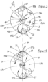
- FIG. 1 to 4 in sectional view a rotary piston pump or rotary vane pump with a pump housing 2.
- the pump chamber 8 is essentially cylindrical.
- a rotary piston is arranged concentrically as a rotor 1 with two vanes 3 lying opposite one another in the circumferential direction.
- the rotor 1 with the vanes 3 encloses the rotor axle tube 18 or in other words the rotor axle tube 18 and the rotor 1 with the vanes 3 form a structural unit.
- the rotor axle tube 18 there is an inlet channel (not shown) to at least two inlet openings 6 in the pump chamber 8 and an outlet channel (not shown) from at least two outlet openings 7 from the pump chamber 8, each extending from the opposite axial ends and separated axially from one another.
- one of the inlet openings 6 is arranged after one of the blades 3 in the direction of rotation 14 and one of the outlet openings 7 is arranged in front of one of the blades 3 in the direction of rotation 14 in the rotor axle tube 18.
- a pressure side 7 or discharge side 7 is formed in front of the respective blade 3 with respect to the direction of rotation 14 and a suction side 6 or inlet side 6 is formed after the respective blade 3 with respect to the direction of rotation 14.
- the sealing flap 4b and the omega flap 4b can be understood as synonymous, so that if the sealing flap 4b is mentioned alone, the omega flap 4b is also included.
- the inlet channel (not shown) and the outlet channel (not shown) are separated by a channel separation 19, which divides the rotor axis tube 18 into two sections transversely to the axial extension.
- sealing flaps 4a, 4b distributed opposite one another in the circumferential direction.
- the sealing flaps 4a, 4b have a curved or circular arc-shaped contour in the radial direction.
- the radial course of the contour of the sealing flaps 4a to the pump housing 8 according to Figure 1 is only slightly curved.
- the sealing flaps 4b shown have, as so-called omega flaps 4b, a circular arc-shaped or partially cylindrical shell-shaped contour radially to the pump housing 8, wherein the circular arc or the partial cylindrical shell is formed over 180 degrees and the respective ends of the omega flaps 4b have the extension 36 with the inlet or outlet radius 23 corresponding to the pump chamber outer diameter 23 of the housing wall of the 2 pump chambers 8.
- sealing flaps 4a, 4b are each designed to be rotatable or pivotable or twistable or displaceable.
- the sealing flaps 4a, 4b are designed according to Figures 1 to 4 for this purpose in or on the pump housing 2 via spokes 33 or pins 13 at a pivot point 28 or pivot point 28 rotatable or pivotally mounted, the pump housing 2 having at least one free space 29 in the area or movement area of the two sealing flaps 4a, 4b in some areas, radially and axially.
- the radially outer and axial housing wall 2 in the area or movement area of the two sealing flaps 4a, 4b thus has an extension 29 into which the respective sealing flaps 4a, 4b can at least partially rotate or rotate through or pivot in, whereby the respective vane 3 can graze or run past the respective sealing flap 4a, 4b with a maximum radial length along or at the respective sealing flap 4a, 4b or can pass the respective sealing flap 4a, 4b.
- the sealing flaps 4a are pivotably mounted on the outer edges 4a in the area of the radially outer housing wall 2 of the pump housing 2 around and via, for example, a continuous or two individual pins 13 at the radially outer, pump housing-side end of the sealing flaps 4a, so that they can pivot into the free space 29 in the radially outer housing wall 2.
- the pins 13 are guided or received, for example, in the housing cover 9, 10 axially delimiting the pump housing 2 or the pump chamber 8.
- the sealing flaps 4b are designed as omega flaps 4b.
- the omega flaps 4b which have a circular arc or partially cylindrical shell shape in their contour, are each guided to a pivot point 28 by means of spokes 33 and are rotatably mounted at this pivot point 28 via a pin 13 in the housing cover 9, 10 of the pump housing.
- the circular arc or partially cylindrical shell-shaped omega flaps 4b protrude into a free space 29 or an extension 29 in the pump housing 2 which has been widened for this purpose.
- the housing covers 9, 10 of the pump housing 2 also have the free space 29 or the extension 29, particularly in the movement range of the omega flaps 4b and the spokes 33.
- the respective wing 3 is thus able to brush along or run past the respectively opening omega flap 4b, while the respective omega flap 4b moves or rotates around the end of the respective wing 3 in a direction opposite to the direction of rotation 14 of the wing 3, without a collision occurring.
- Pump chamber sections 8a are formed by the sealing flaps 4a, 4b, wherein in the direction of rotation 14 the suction side 6 or inlet side 6 is after the sealing flaps 4a, 4b and the pressure side 7 or outlet side 7 is before the sealing flaps 4a, 4b.
- the rotation speed of the wings 3 in the area or movement range of the sealing flaps 4a, 4b is significantly reduced, which simplifies the synchronization of the respective movements and also avoids collisions.
- the free space 29 or the expansion 29 causes a swirling of the fluid, in particular blood, when the sealing flaps 4a, 4b are opened by passing the respective wing 3.
- the pivot point 28 is not arranged centrally but eccentrically in relation to the contour of the circular arc-shaped or partially cylindrical jacket-shaped omega flaps 4b, wherein the pivot point 28 is selected such that when the rotary movement or opening movement of the sealing flaps 4b or omega flaps 4b begins, they detach themselves from all contact points 38 or points of contact 38 on the circular arc or partial cylinder jacket and thus sealing points 38 to the pump housing 2 and in particular to the housing wall 2, the housing covers 9, 10 and their adjacent areas, and thus the turbulence and flushing both at the flap edges and their inner and outer surfaces, in particular through the free areas 29 or the extension 29 and the free space 37 between the omega flap 4b and the wing 3.
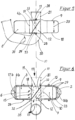
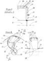
- FIG 7 is a cut of a detail to Figure 3 a part of the pump housing 2 with housing wall 2 and a housing cover 9, the sealing flap 4b as an omega flap 4b with spokes 33, which are guided to a pivot point 28, the rotor axis tube 18 with rotor 1 and vanes 3 as well as the rotor axis 20 as an axis of symmetry and an inlet pipe 21 to the housing cover 9 and rotor axis tube 18 with the inlet channel 11 or the inlet 11 to the rotor axis tube 18.
- a free space 29 or an extension 29 is present in the pump housing 2.
- a distance 37 is radially outside and axially between the respective sealing flap 4b or omega flap 4b and the passing vane 3. As shown, the distance 37 corresponds approximately to the free space 29 or the expansion 29 between the respective sealing flap 4b or omega flap 4b and the radial housing wall 2 widened in the area of the respective sealing flap 4b or omega flap 4b or the axial housing cover 9 widened in this area.
- the wings 3 have an s-shaped and thus multiply curved course in the radial direction.
- the curved course of the contour of the wings 3 in the radial direction and the curved course of the contour of the at least two sealing flaps 4a, 4b are advantageously similar to or adapted to one another, so that as much of the fluid as possible, in particular the blood, can still be conveyed before the sealing flap is opened.
- the wings 3 are designed to be radially straight so that they can easily brush along or run past the sealing flaps 4a, whereby in this flap solution a large angle of rotation range occurs without conveying, since the sealing flap 4a must already be completely open when the incoming wing 3 begins.
- the drive of the blades 3 and the rotor 1 is, as in Figures 1 to 4 shown, by means of magnets 17a at the radial ends of the wings 3 and, as shown in the Figure 2 shown, by means of electromagnets 16a on or in the area of the radial housing wall 2 of the pump housing 2.
- the electromagnets 16a, 16b can be controlled individually and/or as a group, so that different rotation speeds can be set depending on the angular position of the blades 3 as shown above.
- magnets 17b are provided on the sealing flaps 4b or omega flaps 4b, with which the position of the sealing flaps 4b or omega flaps 4b can be changed and, if necessary, held or fixed. Accordingly, electromagnets 16b are provided on the pump housing 2 or on the housing covers 9, 10, which can be controlled accordingly, see for example in Figure 2 .
- the Figure 5 shows a cross-section of the Figure 2 , wherein in the area of the omega flap 4b and in the area of the spokes 33 in the housing covers 9, 10 of the pump housing 2 there is a free space 29 or an extension 29 in which the sealing flap 4b is movably arranged as an omega flap 4b with spokes 33 which are guided to a pivot point 28.
- the inlet pipe 21 in or on the housing cover 9 is shown as the inlet side, to which the inlet channel 11 in the rotor axis tube 18 is connected, followed by the inlet opening (not shown) into the pump chamber 8 with a pump chamber depth 25 which corresponds to the length of the rotor axis tube.
- the outlet opening (not shown) in the rotor axis tube 18 is connected, to which the outlet channel 12 in the rotor axis tube 18 is connected, and followed by the outlet pipe 35 shown below in or on the housing cover 10.
- sail flaps 31 are provided in the outlet pipe 35.
- the rotor axis pipe 18 there is a channel separation 19 which axially separates the inlet channel 11 from the outlet channel 12 at an angle.
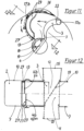
- FIG 6 is a sectional view of a rotary piston pump or rotary vane pump at the end of the pumping process, shortly before the sealing flaps 4b open. While the vanes 3 are still rotating in the direction of the sealing flaps 4b, for example as omega flaps 4b, which have spokes 33 that are guided to the pivot point 28, fluid or blood is still flowing in the flow direction 15 into the pump and pump chamber 8 on the suction side 6 of the vanes 3 and the sealing flap 4b via the inlet pipe 21, the inlet channel 11 and the inlet opening 6 into the pump chamber 8, while on the pressure side 7 of the vanes 3 and the sealing flap 4b, fluid or blood is still flowing out of the pump in the flow direction 15 from the pump chamber 8 via the outlet opening 7, the outlet channel 12 and the outlet pipe 35.
- omega flaps 4b which have spokes 33 that are guided to the pivot point 28
- fluid or blood is still flowing in the flow direction 15 into the pump and pump chamber 8 on the suction side 6 of the vanes 3 and the sealing flap 4b via the inlet pipe 21,
- the electromagnets 16b control the wings 3 with their magnets (not shown) and position them in front of the sealing flaps 4b which are to be opened. braked.
- the sealing flaps 4b with their magnets 17b are controlled by the electromagnets 16b so that the sealing flaps 4b open in time and the vanes 3 rotate slowly and synchronously with the sealing flaps 4b underneath them.
- the rotor 1 with the vanes 3 has a rotor bearing 32 in the housing covers 9, 10 axially delimiting the pump housing 2 at the transition points between the inlet pipe 21 and the rotor shaft pipe 18 and between the rotor shaft pipe 18 and the outlet pipe 35.
- the channel separation 19 is also present in the rotor shaft pipe 18.
- FIG 8 a further embodiment of a vane 3 is shown, which has a sickle-shaped curved contour opposite to the direction of rotation 14 and at the radial ends in the direction of rotation there are projections 22 in the form of a nose or more noses, which are able to press an omega flap 4b, which may not be completely in contact with the radially outer housing wall 2, against the radially outer housing wall 2 for a free passage of the vane 3.
- the approximately tangential extension 36 with the inlet or outlet radius 23 corresponding to the pump chamber outer diameter 23 of the housing wall 2 of the pump chamber 8 or with the pump chamber outer diameter 23 is present on the sealing flap 4b as an omega flap 4b.
- the detail also shows a part of the pump housing 2 with housing wall 2 and the sealing flap 4b as an omega flap 4b with spokes 33, which are guided to a pivot point 28.
- a free space 29 or an extension 29 is present in the pump housing 2.
- the channel separation 19 is also present in the rotor axis tube 18.
- the rotor 1 with the blades 3 has a rotor bearing 32 in the housing covers 9, 10 axially delimiting the pump housing 2 at the transition points between the inlet tube 21 and the rotor axis tube 18 and between the rotor axis tube 18 and the outlet tube 35, as shown in the side view in Figure 8 is shown.
- FIGs 9 and 10 show a combined arrangement of two rotary piston pumps or rotary vane pumps.
- Each of the pumps has its own drive for the rotor 1 or the blades 3.
- FIG 10 there is a common drive for both pumps in the pump shown above, which is constructed as described above, whereby the drive of the second rotor 1 takes place via the rotor axis 20, which is thus a shaft and which is also a component of the rotor 1.
- the rotor bearing 32 of the rotor axis 20 is present in the inlet pipe 21 of the pump shown above and in the outlet pipe 35 of the pump shown below, as well as between the pumps in the transition between the outlet pipe 35 of the pump shown above and the inlet pipe 21 of the pump shown below.
- the two rotor axes 20 can be put together as shafts.
- This arrangement can be used, for example, to create a full heart replacement, since both chambers work synchronously but separately on the flow side, with blood from the direction of the mitral valve 6a being pumped through the lower pump to the aorta 7a, while blood from the direction of the tricuspid valve 6b is pumped through the upper pump to the pulmonary artery 7b.
- FIGS 11 and 12 show a further design of the bearing and guidance of the sealing flap 4b or Omega flap 4b.
- the sealing flaps have webs 13 which comprise pins 13 or balls 13 which can protrude or slide or roll in the guide grooves and thus realize the movement of the sealing flaps 4b and their smooth guidance.
Landscapes
- Health & Medical Sciences (AREA)
- Engineering & Computer Science (AREA)
- Heart & Thoracic Surgery (AREA)
- Mechanical Engineering (AREA)
- Cardiology (AREA)
- Biomedical Technology (AREA)
- Anesthesiology (AREA)
- Hematology (AREA)
- Life Sciences & Earth Sciences (AREA)
- Animal Behavior & Ethology (AREA)
- General Health & Medical Sciences (AREA)
- Public Health (AREA)
- Veterinary Medicine (AREA)
- General Engineering & Computer Science (AREA)
- External Artificial Organs (AREA)
Claims (15)
- Pompe à piston rotatif, comprenant un boîtier de pompe (2, 9, 10) avec une chambre de pompe (8) essentiellement cylindrique et un piston rotatif en tant que rotor (1) avec au moins deux palettes (3) disposées l'une en face de l'autre dans la direction périphérique ou réparties uniformément et au moins une plaque d'étanchéité (4a, 4b),
caractérisée en ce que
il y a au moins deux plaques d'étanchéité (4a, 4b) disposées l'une en face de l'autre dans la direction périphérique ou réparties uniformément, les deux plaques d'étanchéité (4a, 4b) minimales étant rotatives ou pivotantes, et un canal d'entrée (11) vers au moins deux ouvertures d'entrée (6) dans la chambre de pompe (8) et un canal de sortie (12) depuis au moins deux ouvertures d'entrée (7) hors de la chambre de pompe (8) étant présentes dans un tube d'axe de rotor (18) s'étendant respectivement depuis les extrémités axiales opposées et séparés axialement les uns des autres, l'une des ouvertures d'entrée (6) étant disposée dans le sens de rotation (14) après et l'une des ouvertures de sortie (7) étant disposée dans le sens de rotation (14) avant l'une des palettes (3) dans le tube d'axe de rotor (18). - Pompe à piston rotatif selon la revendication 1,
caractérisée en ce que
les palettes (3) sont à symétrie ponctuelle par rapport à l'axe de rotation du tube d'axe de rotor (18) et/ou en ce que le contour des palettes (3) présente un tracé à une ou plusieurs courbures dans la direction radiale et/ou en ce que le contour des deux plaques d'étanchéité (4a, 4b) minimales présente dans la direction radiale un tracé incurvé ou en arc de cercle et/ou que le tracé incurvé dans la direction radiale du contour des palettes (3) et le tracé incurvé du contour des deux plaques d'étanchéité (4a, 4b) minimales sont similaires ou adaptées ou congruentes entre elles. - Pompe à piston rotatif selon l'une des revendications précédentes,
caractérisée en ce que
les deux plaques d'étanchéité (4a, 4b) minimales présentent, au moins à l'extrémité tournée respectivement vers la paroi de boîtier (2) radialement extérieure de la chambre de pompe (8), un prolongement (36) rectiligne approximativement tangentiel ou un prolongement (36) avec un rayon d'entrée ou de sortie (23) correspondant au diamètre extérieur (23) de la paroi de boîtier (2) de la chambre de pompe (8) ou un diamètre extérieur (24) de la chambre de pompe. - Pompe à piston rotatif selon l'une des revendications précédentes,
caractérisée en ce que
les deux plaques d'étanchéité (4a, 4b) minimales sont montées ou disposées dans ou sur le boîtier de pompe (2) de manière à pouvoir glisser ou tourner ou pivoter sur un point de rotation (28) ou un point de pivotement ou dans des rails (27) ou dans ou sur des guides (27) par l'intermédiaire de rayons (33) ou d'entretoises (35) ou de cames (13) ou de goupilles ou de billes, le boîtier de pompe (2) présentant au moins un espace libre (29) dans la zone ou la zone de mouvement des deux plaques d'étanchéité (4a, 4b) minimales, au moins par zones, radialement et/ou axialement. - Pompe à piston rotatif selon l'une des revendications précédentes,
caractérisée en ce que
les deux plaques d'étanchéité (4a, 4b) minimales peuvent être tournées ou pivotées ou tournées de manière concentrique ou excentrique. - Pompe à piston rotatif selon l'une des revendications précédentes,
caractérisée en ce que
le boîtier de pompe (2) présente des électroaimants (16a, 16b) répartis de manière régulière et/ou irrégulière au moins dans la zone radialement extérieure sur la périphérie et/ou sur l'extension axiale et/ou dans la zone des plaques d'étanchéité (4). - Pompe à piston rotatif selon l'une des revendications précédentes,
caractérisée en ce que
au moins un aimant (17b) est présent sur les deux plaques d'étanchéité (4a, 4b) minimales et/ou en ce qu'au moins un aimant (17a) est présent au moins à l'extrémité radialement extérieure des palettes. - Pompe à piston rotatif selon l'une des revendications précédentes,
caractérisée en ce que
les électroaimants (16a, 16b) peuvent être commandés individuellement et/ou en groupe. - Pompe à piston rotatif selon l'une des revendications précédentes,
caractérisée en ce que
les deux plaques d'étanchéité (4a, 4b) présentent chacune au moins un joint d'étanchéité et/ou une soupape de décharge (26) ou une dérivation (26) commandée par dépression dans le clapet d'étanchéité respectif (4a, 4b) ou sur ou dans le corps (2) ou le rotor (1) entre la pression (7) ou l'évacuation (7) et l'aspiration (6) ou l'alimentation (6). - Pompe à piston rotatif selon l'une des revendications précédentes,
caractérisée en ce que
les palettes présentent radialement dans la zone du corps de pompe dans le sens de rotation (14) une saillie (22) et/ou en ce que les palettes (3) et/ou le boîtier de pompe (2) présentent dans la zone des plaques d'étanchéité (4a, 4b) une soupape de décharge (26) ou une dérivation commandée par dépression (26) entre la pression (7) ou l'écoulement (7) et l'aspiration (6) ou l'arrivée (6). - Pompe à piston rotatif selon l'une des revendications précédentes,
caractérisée en ce que
le canal de sortie (12) ou le tube d'axe de rotor (12) pour la sortie ou le tube de sortie (35) présente un tracé ou une section transversale intérieure enroulé ou hélicoïdal. - Procédé pour faire fonctionner une pompe à piston rotatif, de préférence pour faire fonctionner une pompe à piston rotatif selon les revendications 1 à 13, dans lequel, dans une chambre de pompe (8) sensiblement cylindrique d'un boîtier de pompe (2), par le mouvement de rotation d'un piston rotatif en tant que rotor (1) avec un tube d'axe de rotor (18) et avec au moins deux palettes (3) disposées en face l'une de l'autre dans la direction périphérique ou réparties de manière régulière, un fluide est introduit dans la chambre de pompe (8). fluide est pressé dans une ouverture de sortie (7) respective dans le tube d'axe de rotor (18) dans le sens de rotation (14) en amont de la pale respective (3) et, en même temps, le fluide est aspiré par une ouverture d'entrée (6) dans le tube d'axe de rotor (18) dans le sens de rotation (14) en aval de la pale respective (3), une séparation des zones de la pression (7) ou de l'évacuation (7) et de l'aspiration (6) ou de l'entrée (6) étant effectuée respectivement au moyen d'une plaque d'étanchéité (4a, 4b) et la plaque d'étanchéité respective (4a, 4b) se trouve dans une position fermée pour la pression (7) ou l'écoulement (7) et l'aspiration (6) ou l'arrivée (6) et, après la pression (7) ou l'écoulement (7) ainsi qu'après l'aspiration (6) ou l'arrivée (6) pour le passage de la pale (3) respective, la plaque d'étanchéité (4a, 4b) est pivotée vers la zone radialement extérieure de la chambre de pompe (8) ou est tournée autour de l'extrémité radialement extérieure de la pale respective (3) et, après le passage, la plaque d'étanchéité respective (4a, 4b) est à nouveau déplacée dans une position fermée et ensuite la pression (7) ou l'écoulement (7) et l'aspiration (6) ou l'arrivée (6) ont à nouveau lieu.
- Procédé selon la revendication 12,
caractérisée en ce que
le mouvement de rotation du piston rotatif en tant que rotor (1) s'effectue avec une vitesse de rotation différente selon la position angulaire des palettes (3) et/ou en ce que le mouvement de rotation du piston rotatif en tant que rotor (1) est réduit lorsque la pale (3) respective se trouve dans la zone de la plaque d'étanchéité (4a, 4b) respective. - Procédé selon l'une des revendications 12 et 13,
caractérisée en ce que
le réglage du mouvement de rotation du piston rotatif en tant que rotor (1) et/ou de la position des plaques d'étanchéité (4a, 4b) s'effectue au moyen de la commande d'électroaimants (16a, 16b) et/ou en ce que le mouvement de rotation du rotor (1), la position des plaques d'étanchéité (4a, 4b) et/ou d'autres données sont détectées comme base pour le fonctionnement de la pompe et le fonctionnement de la pompe est commandé. - Utilisation de la pompe à piston rotatif selon l'une des revendications 1 à 11 comme pompe cardiaque pour assister le coeur humain ou comme substitut cardiaque.
Applications Claiming Priority (1)
| Application Number | Priority Date | Filing Date | Title |
|---|---|---|---|
| DE102020132226 | 2020-12-03 |
Publications (4)
| Publication Number | Publication Date |
|---|---|
| EP4008904A1 EP4008904A1 (fr) | 2022-06-08 |
| EP4008904A9 EP4008904A9 (fr) | 2023-04-19 |
| EP4008904C0 EP4008904C0 (fr) | 2024-12-25 |
| EP4008904B1 true EP4008904B1 (fr) | 2024-12-25 |
Family
ID=81393218
Family Applications (1)
| Application Number | Title | Priority Date | Filing Date |
|---|---|---|---|
| EP21212330.1A Active EP4008904B1 (fr) | 2020-12-03 | 2021-12-03 | Pompe d'assistance cardiaque |
Country Status (3)
| Country | Link |
|---|---|
| US (1) | US12151093B2 (fr) |
| EP (1) | EP4008904B1 (fr) |
| DE (1) | DE102021131924A1 (fr) |
Family Cites Families (7)
| Publication number | Priority date | Publication date | Assignee | Title |
|---|---|---|---|---|
| US2501947A (en) * | 1944-05-17 | 1950-03-28 | James P Johnson | Hydraulic pump |
| DE6927594U (de) | 1969-07-12 | 1971-08-12 | Braunschweigische Maschb Nstal | Drehkolbenpumpe. |
| US6576010B2 (en) * | 2000-07-20 | 2003-06-10 | Izaak A. Ulert | Circular artificial heart |
| DE102004005468B4 (de) | 2004-02-03 | 2013-11-21 | Franz-Harro Horn | Rotationskolbenmaschine |
| DE102014010745A1 (de) * | 2014-07-23 | 2016-02-11 | Rheinisch-Westfälische Technische Hochschule Aachen | Rotationskolbenpumpe |
| DE202016000016U1 (de) | 2016-01-04 | 2016-01-25 | Heinz Prümer | Drehkolbenpumpe |
| ES2742404T3 (es) * | 2016-04-12 | 2020-02-14 | Centre Hospitalier Univ Vaudois Chuv | Bomba para corazón artificial y su unidad de accionamiento |
-
2021
- 2021-12-03 EP EP21212330.1A patent/EP4008904B1/fr active Active
- 2021-12-03 DE DE102021131924.2A patent/DE102021131924A1/de active Pending
- 2021-12-03 US US17/541,302 patent/US12151093B2/en active Active
Also Published As
| Publication number | Publication date |
|---|---|
| DE102021131924A1 (de) | 2022-06-09 |
| EP4008904C0 (fr) | 2024-12-25 |
| US20220176099A1 (en) | 2022-06-09 |
| EP4008904A1 (fr) | 2022-06-08 |
| EP4008904A9 (fr) | 2023-04-19 |
| US12151093B2 (en) | 2024-11-26 |
Similar Documents
| Publication | Publication Date | Title |
|---|---|---|
| DE19535781C2 (de) | Vorrichtung zur aktiven Strömungsunterstützung von Körperflüssigkeiten | |
| EP1261385B1 (fr) | Pompe a sang | |
| DE69027029T2 (de) | Herzunterstützungspumpe | |
| DE3280454T2 (de) | Magnetisch gelagerter und angetriebener Kreiselpumpenapparat. | |
| DE69931960T2 (de) | Blutpumpe unter anwendung des querströmungsprinzips | |
| EP2607712B1 (fr) | Boîtier de pompe doté d'un espace intérieur destiné à la réception d'un rotor de pompe | |
| DE60301135T2 (de) | Blutpumpe mit axialem und radialem durchfluss und mit doppeltem eingang | |
| EP0905379B1 (fr) | Pompe centrifuge et système des pompes centrifuges | |
| DE60224025T2 (de) | Künstliches herz | |
| WO2011131766A1 (fr) | Dispositif d'assistance cardiaque | |
| DE2819851A1 (de) | Kuenstliches herz | |
| EP1374928B1 (fr) | Pompe à sang à turbine | |
| DE3510650A1 (de) | Blutpumpe | |
| DE68907576T2 (de) | Verdrängerpumpe. | |
| WO2008012007A1 (fr) | Système à deux chambres implantable destiné à supporter le ventricule gauche du coeur | |
| EP4008904B1 (fr) | Pompe d'assistance cardiaque | |
| DE3133177A1 (de) | Hermetisch gekapselte kreiselpumpe zur schonenden foerderung von fluiden | |
| EP4427796A1 (fr) | Système comprenant une pompe à sang et une unité de commande et procédé de fonctionnement d'une pompe à sang | |
| DE102020132268B3 (de) | Künstliches herz | |
| DE2361023A1 (de) | Herzpumpe | |
| DE202015001252U1 (de) | Kunstherz | |
| DE102014211014A1 (de) | Kunstherz | |
| DE2558921A1 (de) | Antrieb fuer eine pneumatische oder hydraulische pulspumpe | |
| WO2009127704A1 (fr) | Système de pompe davg et procédé pour faire fonctionner un système de pompe | |
| DE202015009444U1 (de) | Implantierbares Pumpensystem |
Legal Events
| Date | Code | Title | Description |
|---|---|---|---|
| STAA | Information on the status of an ep patent application or granted ep patent |
Free format text: STATUS: UNKNOWN |
|
| PUAI | Public reference made under article 153(3) epc to a published international application that has entered the european phase |
Free format text: ORIGINAL CODE: 0009012 |
|
| STAA | Information on the status of an ep patent application or granted ep patent |
Free format text: STATUS: THE APPLICATION HAS BEEN PUBLISHED |
|
| AK | Designated contracting states |
Kind code of ref document: A1 Designated state(s): AL AT BE BG CH CY CZ DE DK EE ES FI FR GB GR HR HU IE IS IT LI LT LU LV MC MK MT NL NO PL PT RO RS SE SI SK SM TR |
|
| STAA | Information on the status of an ep patent application or granted ep patent |
Free format text: STATUS: REQUEST FOR EXAMINATION WAS MADE |
|
| 17P | Request for examination filed |
Effective date: 20221125 |
|
| RBV | Designated contracting states (corrected) |
Designated state(s): AL AT BE BG CH CY CZ DE DK EE ES FI FR GB GR HR HU IE IS IT LI LT LU LV MC MK MT NL NO PL PT RO RS SE SI SK SM TR |
|
| RAP1 | Party data changed (applicant data changed or rights of an application transferred) |
Owner name: RAP-P MEDITEC UG |
|
| RIN1 | Information on inventor provided before grant (corrected) |
Inventor name: HORN, FRANZ-HARRO |
|
| GRAP | Despatch of communication of intention to grant a patent |
Free format text: ORIGINAL CODE: EPIDOSNIGR1 |
|
| STAA | Information on the status of an ep patent application or granted ep patent |
Free format text: STATUS: GRANT OF PATENT IS INTENDED |
|
| RIC1 | Information provided on ipc code assigned before grant |
Ipc: A61M 60/258 20210101ALI20240802BHEP Ipc: A61M 60/896 20210101ALI20240802BHEP Ipc: A61M 60/894 20210101ALI20240802BHEP Ipc: A61M 60/835 20210101ALI20240802BHEP Ipc: A61M 60/441 20210101ALI20240802BHEP Ipc: A61M 60/196 20210101ALI20240802BHEP Ipc: F04C 15/06 20060101ALI20240802BHEP Ipc: F04C 13/00 20060101ALI20240802BHEP Ipc: F04C 2/22 20060101AFI20240802BHEP |
|
| INTG | Intention to grant announced |
Effective date: 20240902 |
|
| GRAS | Grant fee paid |
Free format text: ORIGINAL CODE: EPIDOSNIGR3 |
|
| GRAA | (expected) grant |
Free format text: ORIGINAL CODE: 0009210 |
|
| STAA | Information on the status of an ep patent application or granted ep patent |
Free format text: STATUS: THE PATENT HAS BEEN GRANTED |
|
| AK | Designated contracting states |
Kind code of ref document: B1 Designated state(s): AL AT BE BG CH CY CZ DE DK EE ES FI FR GB GR HR HU IE IS IT LI LT LU LV MC MK MT NL NO PL PT RO RS SE SI SK SM TR |
|
| REG | Reference to a national code |
Ref country code: GB Ref legal event code: FG4D Free format text: NOT ENGLISH |
|
| REG | Reference to a national code |
Ref country code: CH Ref legal event code: EP |
|
| REG | Reference to a national code |
Ref country code: DE Ref legal event code: R096 Ref document number: 502021006200 Country of ref document: DE |
|
| REG | Reference to a national code |
Ref country code: IE Ref legal event code: FG4D Free format text: LANGUAGE OF EP DOCUMENT: GERMAN |
|
| U01 | Request for unitary effect filed |
Effective date: 20250110 |
|
| U07 | Unitary effect registered |
Designated state(s): AT BE BG DE DK EE FI FR IT LT LU LV MT NL PT RO SE SI Effective date: 20250117 |
|
| PG25 | Lapsed in a contracting state [announced via postgrant information from national office to epo] |
Ref country code: HR Free format text: LAPSE BECAUSE OF FAILURE TO SUBMIT A TRANSLATION OF THE DESCRIPTION OR TO PAY THE FEE WITHIN THE PRESCRIBED TIME-LIMIT Effective date: 20241225 |
|
| PG25 | Lapsed in a contracting state [announced via postgrant information from national office to epo] |
Ref country code: NO Free format text: LAPSE BECAUSE OF FAILURE TO SUBMIT A TRANSLATION OF THE DESCRIPTION OR TO PAY THE FEE WITHIN THE PRESCRIBED TIME-LIMIT Effective date: 20250325 |
|
| PG25 | Lapsed in a contracting state [announced via postgrant information from national office to epo] |
Ref country code: GR Free format text: LAPSE BECAUSE OF FAILURE TO SUBMIT A TRANSLATION OF THE DESCRIPTION OR TO PAY THE FEE WITHIN THE PRESCRIBED TIME-LIMIT Effective date: 20250326 |
|
| PG25 | Lapsed in a contracting state [announced via postgrant information from national office to epo] |
Ref country code: RS Free format text: LAPSE BECAUSE OF FAILURE TO SUBMIT A TRANSLATION OF THE DESCRIPTION OR TO PAY THE FEE WITHIN THE PRESCRIBED TIME-LIMIT Effective date: 20250325 |
|
| U1N | Appointed representative for the unitary patent procedure changed after the registration of the unitary effect |
Representative=s name: SCHIED, SEBASTIAN; DE |
|
| PG25 | Lapsed in a contracting state [announced via postgrant information from national office to epo] |
Ref country code: SM Free format text: LAPSE BECAUSE OF FAILURE TO SUBMIT A TRANSLATION OF THE DESCRIPTION OR TO PAY THE FEE WITHIN THE PRESCRIBED TIME-LIMIT Effective date: 20241225 |
|
| PG25 | Lapsed in a contracting state [announced via postgrant information from national office to epo] |
Ref country code: PL Free format text: LAPSE BECAUSE OF FAILURE TO SUBMIT A TRANSLATION OF THE DESCRIPTION OR TO PAY THE FEE WITHIN THE PRESCRIBED TIME-LIMIT Effective date: 20241225 |
|
| PG25 | Lapsed in a contracting state [announced via postgrant information from national office to epo] |
Ref country code: ES Free format text: LAPSE BECAUSE OF FAILURE TO SUBMIT A TRANSLATION OF THE DESCRIPTION OR TO PAY THE FEE WITHIN THE PRESCRIBED TIME-LIMIT Effective date: 20241225 |
|
| PG25 | Lapsed in a contracting state [announced via postgrant information from national office to epo] |
Ref country code: IS Free format text: LAPSE BECAUSE OF FAILURE TO SUBMIT A TRANSLATION OF THE DESCRIPTION OR TO PAY THE FEE WITHIN THE PRESCRIBED TIME-LIMIT Effective date: 20250425 |
|
| PG25 | Lapsed in a contracting state [announced via postgrant information from national office to epo] |
Ref country code: SK Free format text: LAPSE BECAUSE OF FAILURE TO SUBMIT A TRANSLATION OF THE DESCRIPTION OR TO PAY THE FEE WITHIN THE PRESCRIBED TIME-LIMIT Effective date: 20241225 |
|
| PG25 | Lapsed in a contracting state [announced via postgrant information from national office to epo] |
Ref country code: CZ Free format text: LAPSE BECAUSE OF FAILURE TO SUBMIT A TRANSLATION OF THE DESCRIPTION OR TO PAY THE FEE WITHIN THE PRESCRIBED TIME-LIMIT Effective date: 20241225 |
|
| PLBE | No opposition filed within time limit |
Free format text: ORIGINAL CODE: 0009261 |
|
| STAA | Information on the status of an ep patent application or granted ep patent |
Free format text: STATUS: NO OPPOSITION FILED WITHIN TIME LIMIT |
|
| 26N | No opposition filed |
Effective date: 20250926 |
|
| U20 | Renewal fee for the european patent with unitary effect paid |
Year of fee payment: 5 Effective date: 20251222 |