EP4008939B1 - Soupape de limitation de vide - Google Patents
Soupape de limitation de vide Download PDFInfo
- Publication number
- EP4008939B1 EP4008939B1 EP21211077.9A EP21211077A EP4008939B1 EP 4008939 B1 EP4008939 B1 EP 4008939B1 EP 21211077 A EP21211077 A EP 21211077A EP 4008939 B1 EP4008939 B1 EP 4008939B1
- Authority
- EP
- European Patent Office
- Prior art keywords
- valve
- holding element
- cover
- cleaning device
- holding
- Prior art date
- Legal status (The legal status is an assumption and is not a legal conclusion. Google has not performed a legal analysis and makes no representation as to the accuracy of the status listed.)
- Active
Links
Images

Classifications
-
- F—MECHANICAL ENGINEERING; LIGHTING; HEATING; WEAPONS; BLASTING
- F16—ENGINEERING ELEMENTS AND UNITS; GENERAL MEASURES FOR PRODUCING AND MAINTAINING EFFECTIVE FUNCTIONING OF MACHINES OR INSTALLATIONS; THERMAL INSULATION IN GENERAL
- F16K—VALVES; TAPS; COCKS; ACTUATING-FLOATS; DEVICES FOR VENTING OR AERATING
- F16K15/00—Check valves
- F16K15/02—Check valves with guided rigid valve members
- F16K15/06—Check valves with guided rigid valve members with guided stems
- F16K15/063—Check valves with guided rigid valve members with guided stems the valve being loaded by a spring
-
- A—HUMAN NECESSITIES
- A47—FURNITURE; DOMESTIC ARTICLES OR APPLIANCES; COFFEE MILLS; SPICE MILLS; SUCTION CLEANERS IN GENERAL
- A47L—DOMESTIC WASHING OR CLEANING; SUCTION CLEANERS IN GENERAL
- A47L9/00—Details or accessories of suction cleaners, e.g. mechanical means for controlling the suction or for effecting pulsating action; Storing devices specially adapted to suction cleaners or parts thereof; Carrying-vehicles specially adapted for suction cleaners
- A47L9/0072—Mechanical means for controlling the suction or for effecting pulsating action
-
- A—HUMAN NECESSITIES
- A47—FURNITURE; DOMESTIC ARTICLES OR APPLIANCES; COFFEE MILLS; SPICE MILLS; SUCTION CLEANERS IN GENERAL
- A47L—DOMESTIC WASHING OR CLEANING; SUCTION CLEANERS IN GENERAL
- A47L9/00—Details or accessories of suction cleaners, e.g. mechanical means for controlling the suction or for effecting pulsating action; Storing devices specially adapted to suction cleaners or parts thereof; Carrying-vehicles specially adapted for suction cleaners
- A47L9/28—Installation of the electric equipment, e.g. adaptation or attachment to the suction cleaner; Controlling suction cleaners by electric means
- A47L9/2889—Safety or protection devices or systems, e.g. for prevention of motor over-heating or for protection of the user
-
- F—MECHANICAL ENGINEERING; LIGHTING; HEATING; WEAPONS; BLASTING
- F16—ENGINEERING ELEMENTS AND UNITS; GENERAL MEASURES FOR PRODUCING AND MAINTAINING EFFECTIVE FUNCTIONING OF MACHINES OR INSTALLATIONS; THERMAL INSULATION IN GENERAL
- F16K—VALVES; TAPS; COCKS; ACTUATING-FLOATS; DEVICES FOR VENTING OR AERATING
- F16K31/00—Actuating devices; Operating means; Releasing devices
- F16K31/003—Actuating devices; Operating means; Releasing devices operated without a stable intermediate position, e.g. with snap action
-
- F—MECHANICAL ENGINEERING; LIGHTING; HEATING; WEAPONS; BLASTING
- F16—ENGINEERING ELEMENTS AND UNITS; GENERAL MEASURES FOR PRODUCING AND MAINTAINING EFFECTIVE FUNCTIONING OF MACHINES OR INSTALLATIONS; THERMAL INSULATION IN GENERAL
- F16K—VALVES; TAPS; COCKS; ACTUATING-FLOATS; DEVICES FOR VENTING OR AERATING
- F16K31/00—Actuating devices; Operating means; Releasing devices
- F16K31/02—Actuating devices; Operating means; Releasing devices electric; magnetic
- F16K31/06—Actuating devices; Operating means; Releasing devices electric; magnetic using a magnet, e.g. diaphragm valves, cutting off by means of a liquid
- F16K31/08—Actuating devices; Operating means; Releasing devices electric; magnetic using a magnet, e.g. diaphragm valves, cutting off by means of a liquid using a permanent magnet
- F16K31/084—Actuating devices; Operating means; Releasing devices electric; magnetic using a magnet, e.g. diaphragm valves, cutting off by means of a liquid using a permanent magnet the magnet being used only as a holding element to maintain the valve in a specific position, e.g. check valves
Definitions
- the invention relates to a cleaning device with a vacuum limiting valve, which is used in particular as a secondary air valve of a suction cleaning device.
- a vacuum relief valve is usually used in compressors, especially for extracting air. This is particularly the case when forced-feed compressors, such as side channel compressors, are used. Such vacuum relief valves are also referred to as bypass air valves.
- the vacuum relief valve prevents overloading when driving the compressor, thereby avoiding damage.
- the valve opens as soon as the flow resistance in the air flow line (suction line) increases or is blocked and a significant pressure difference forms in the compressor.
- Conventional valves have a mechanical spring for this purpose.
- the linear spring force the valve opens further and further the higher the pressure difference in the compressor is in order to compensate for the lack of pressure or the lack of air volume flow.
- the spring closes the valve automatically as soon as the differential pressure falls below a certain value.
- the problem here is that due to the linear spring force, the valve already begins to open, even if critical overloading of the drive is not yet expected. Pressure and flow losses occur as a result of the early slight opening of the valve.
- EP 0 955 003 A1 shows a known cleaning device with a vacuum relief valve.
- the vacuum limiting valve should not be closed primarily by an elastic element, such as a spring, but rather a permanent magnet should be used.
- a permanent magnet By using the permanent magnet to close the vacuum limiting valve, its opening movement is no longer dependent on the linear spring force, but can be opened completely very abruptly and essentially immediately when a predetermined pressure difference is reached.
- the vacuum limiting valve presented here comprises a base with a valve opening.
- a valve seat is formed on the inside of the valve opening.
- this valve seat surrounds the valve opening in a ring shape.
- the seal is preferably elastic to compensate for tolerances.
- the base is preferably plate-shaped and is integrated into a compressor on the suction side or installed in the suction line that leads to the compressor.
- the valve opening in the base leads from an inside of the vacuum relief valve to an outside of the vacuum relief valve. When the vacuum relief valve is used, the inside of the base is subjected to the negative pressure.
- the valve opening preferably leads to the atmosphere.
- the vacuum limiting valve also includes a valve cover that seals against the valve seat when the valve is closed.
- the valve cover rests against the inside of the valve seat.
- the valve cover can be moved inwards to release the valve opening and thus open the vacuum limiting valve.
- a seal can also be used on the corresponding surface of the valve cover.
- valve cover moves inwards and away from the valve seat when the differential pressure is sufficiently high (compared to the atmosphere). This opens the vacuum relief valve.
- the vacuum limiting valve comprises a locking device.
- This locking device is made up of two holding elements that magnetically attract each other.
- the first holding element is arranged in a fixed position.
- the second holding element is connected to the valve cover. At least one of the two holding elements is a permanent magnet.
- the other holding element can also be a permanent magnet or is made of ferromagnetic material. It is particularly preferred that the second holding element is a permanent magnet and the first holding element is a steel plate.
- the vacuum limiting valve When closed, the vacuum limiting valve is held shut by the two retaining elements that attract each other. In particular, the two retaining elements rest against each other. The valve cover is pulled inwards by a sufficiently high negative pressure on the inside of the vacuum limiting valve. The second retaining element also moves with the valve cover and thus moves away from the first retaining element.
- the vacuum limiting valve comprises an elastic element which urges the valve cover towards its closed position.
- the elastic element is in particular a spring, for example a spiral-shaped compression spring.
- the holding force of the vacuum limiting valve is generated primarily by the magnetically attracted holding elements.
- the elastic element is only intended for fine adjustment of the opening differential pressure or for secure closing.
- a magnetic force Fm acts on the valve cover, defined in the closed position.
- a spring force Ff acts on the valve cover through the elastic element.
- This force is referred to here as "spring force”, but can also be generated by an elastic element other than a spring. In particular, the spring force is generated in the closed position of the valve cover by pre-tensioning the elastic element accordingly.
- the magnetic force Fm in the closed position is greater than the spring force Ff.
- the magnetic force Fm is at least twice the spring force Ff, more preferably the magnetic force Fm is at least five times the spring force Ff, particularly preferably the magnetic force Fm is at least ten times the spring force Ff.
- the vacuum limiting valve is "controllable". This means that the vacuum limiting valve cannot be controlled electrically, hydraulically, pneumatically or in any other way and can therefore be opened or closed.
- the vacuum limiting valve is only opened or closed depending on the negative pressure on the inside of the vacuum limiting valve.
- the locking device and the entire vacuum limiting valve do not have an electromagnet.
- valve cover is connected to a valve rod.
- the second holding element in particular the permanent magnet, is preferably located on the valve rod.
- the valve rod is connected to the valve cover at its inner end and extends outwards through the valve opening.
- the second holding element is arranged in particular at the outer end of the valve rod.
- the elastic element is preferably designed as a compression spring and sits on the valve rod.
- a nut is mounted on the valve rod. is screwed on, against which the elastic element rests. The spring force can be adjusted using this nut.
- the base comprises a support region that extends across the valve opening.
- the valve rod can run through this support region and can be guided in a linearly movable manner in the support region.
- the elastic element in particular designed as a compression spring, rests against this support region.
- the support region is preferably designed such that it covers as little area of the valve opening as possible.
- valve rod extends parallel to a valve axis.
- the valve cover is opened along this valve axis, so that the opening direction of the valve cover is aligned parallel to the valve axis and thus parallel to the valve rod.
- the second holding element can be moved away from the first holding element parallel to the opening direction in order to open the valve cover.
- the first holding element in particular designed as a steel plate, is fastened to the base by means of a fastening device.
- the fastening device has one or more feet that extend to the side of the valve rod.
- the fastening device encompasses the valve rod and the first holding element can be arranged opposite the outer end of the valve rod.
- the fastening device is particularly preferably manufactured in one piece together with the first holding element, designed as a steel plate.
- valve rod and/or the second holding element is/are guided in a linearly movable manner on a guide of the fastening device.
- the valve rod is preferably guided not only in the area of the base, but also at the opposite end in the area of the fastening device. Since the second holding element is located here, this holding element can also be guided instead of the valve rod.
- the invention provides that the first holding element is movably arranged on the fastening device so that an overlap of the first holding element with the second holding element is adjustable, whereby the magnetic force Fm can be adjusted.
- the identically constructed vacuum limiting valve can be used for different compressors, with the required magnetic force Fm being adjusted during assembly.
- the first holding element is preferably movable horizontally to the opening direction of the valve.
- the defined relation of the magnetic force Fm to the spring force Ff preferably refers to the maximum adjustable magnetic force Fm and the maximum adjustable spring force Ff, provided that the spring force is also adjustable.
- the fastening device preferably comprises a base body, which is connected in particular to the base and surrounds the valve rod.
- a cover of the fastening device is preferably rotatably mounted on the base body, wherein the first holding element is arranged between the base body and the cover and can be moved relative to the base body by rotating the cover.
- the cover and/or the base body is/are preferably made of non-magnetizable material, in particular plastic.
- the first holding element is guided on the base body and is moved via a slotted guide formed between the cover and the first holding element, in particular in a plane horizontal to the opening direction.
- the invention further comprises a compressor.
- the compressor is designed in particular as a side channel compressor.
- the compressor is designed to suck in gas, in particular air.
- the compressor comprises the vacuum limiting valve described here.
- the invention further comprises a cleaning device with a compressor.
- the compressor is again preferably a side channel compressor.
- the cleaning device is designed to suck in air, possibly including impurities, and comprises a vacuum limiting valve described here in the suction line or directly on the suction side in the compressor.
- the vacuum limiting valve is arranged here as a secondary air valve.
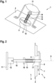
- Fig. 1 and 2 show that a vacuum limiting valve 1 not according to the invention with a base 2.
- An inner side 3 and an outer side 4 are defined on the base 2.
- a valve opening 5 is provided in the base 2, which connects the inner side 3, which is usually subjected to internal pressure, with the outside side 4 on the atmospheric side.
- valve seat 7 On the inside of the valve opening 5 there is a valve seat 7, in the example shown formed by a seal 6.
- a valve cover 8 rests on the valve seat 7 and can be opened inwards along a valve axis 9.
- the valve cover 8 is connected to a valve rod 10.
- the valve rod 10 extends outwards along the valve axis 9.
- the vacuum limiting valve 1 has a magnetic locking device.
- This comprises a first holding element 11, which is fixed in place (or according to Fig.4 movable) and is implemented as a steel plate in the embodiment shown.
- the first holding element 11 interacts with a second holding element 12.
- the second holding element 12 is designed as a permanent magnet and is located on the outside end of the valve rod 10.
- the vacuum limiting valve 1 is closed. Accordingly, the valve cover 8 rests on the valve seat 7 and the second holding element 12 rests on the first holding element 11.
- Fig.1 clarifies in the schematic representation a fastening device 13 which is fastened to the outside of the base 2 and is used to position the first holding element 11 opposite the outer end of the valve rod 10 or opposite the second holding element 12.
- this fastening device 13 has two feet which extend from the base 2. These feet are formed in one piece with the first holding element 11 which is designed as a steel plate.
- Fig.1 further shows that a support region 14 extends across the valve opening 5, which can be an integral part of the base 2. The valve rod 10 runs through the support region 14 and can be guided in a linearly movable manner in the support region 14.
- the Fig. 1 and 2 an elastic element 15, here designed as a spiral compression spring on the valve rod 10.
- the elastic element 15 can be prestressed by means of a nut 16, accordingly the elastic element 15 is supported on the one hand against the nut 16 and on the other hand against the support area 14.
- a stop 17 can be used to limit an opening movement of the valve cover 8 or the valve rod 10.
- this stop 17 is formed by a sleeve that is placed on the valve rod 10. When the vacuum limiting valve 1 is opened sufficiently large, the nut 16 strikes the sleeve-shaped stop 17.
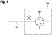
- Fig.3 shows purely schematically a cleaning device 100 with a compressor 101, in particular designed as a side channel compressor.
- the cleaning device 100 serves to extract air, possibly including impurities. This takes place via a corresponding suction line 102.
- the vacuum limiting valve 1 is arranged as a secondary air valve according to one of the two embodiments.
- Fig.4 shows the vacuum limiting valve 1 according to the second embodiment of the invention in section. Identical or functionally identical components are provided with the same reference numerals in both embodiments.
- the two vacuum limiting valves 1 according to the two embodiments are functionally identical; except for the following differences:
- the second holding element 12 is guided in a linearly movable manner on a guide 20 of the fastening device 13.
- the valve rod 10 is guided not only at the support area 14, but also at the opposite end in the area of the fastening device 13. Since the second holding element 12 is located here, this holding element 12 is guided instead of the valve rod 10.
- the first holding element 11 is movably arranged on the fastening device 13, so that an overlap of the first holding element 11 with the second holding element 12 is adjustable, whereby the magnetic force Fm can be adjusted.
- the first holding element 11 can be moved perpendicular to the valve axis 9.
- the fastening device 13 comprises a base body 18, which is connected to the base 2 and surrounds the valve rod 10.
- a cover 19 of the fastening device 13 is rotatably mounted on the base body 18, wherein the first holding element 11 is arranged between the base body 18 and the cover 19 and by rotating the cover 19 relative to the Base body 18 is movable.
- the first holding element 11 is guided on the base body 18 and is moved, for example, via a guide rail formed between the cover 19 and the first holding element 11.
- the base body 18 has a groove 21.
- the cover 19 is secured against removal by means of a locking element 22 which projects into this groove and is simultaneously rotatable, whereby the angle of rotation of the cover 19 and thus the set magnetic force can be fixed by further screwing in the locking element 22.
Landscapes
- Engineering & Computer Science (AREA)
- General Engineering & Computer Science (AREA)
- Mechanical Engineering (AREA)
- Safety Valves (AREA)
- Compressors, Vaccum Pumps And Other Relevant Systems (AREA)
Claims (9)
- Dispositif de nettoyage comprenant un compresseur (101), en particulier un compresseur de canal latéral, destiné à aspirer de l'air et une soupape de limitation de vide (1) en tant que soupape d'air auxiliaire dans le conduit d'aspiration (102) ou dans le compresseur (101), dans lequel la soupape de limitation de vide (1) comprend :- une base (2) avec une ouverture de soupape (5) et un siège de soupape (7) entourant côté intérieur l'ouverture de soupape (5),- un couvercle de soupape (8), qui repose de manière étanche sur le siège de soupape (7) et peut être déplacé vers l'intérieur pour dégager l'ouverture de soupape (5),- un dispositif de blocage maintenant le couvercle de soupape (8) dans le siège de soupape (7) avec deux éléments de maintien (11, 12) s'attirant magnétiquement, dans lequel le premier élément de maintien (11) est disposé de manière stationnaire et le deuxième élément de maintien (12) est relié au couvercle de soupape (8), et dans lequel au moins un des deux éléments de maintien (11, 12) est un aimant permanent,- et un élément élastique (15), qui soumet le couvercle de soupape (8) à une action dans sa position de fermeture,
dans lequel le premier élément de maintien (11) est fixé sur la base (2) au moyen d'un dispositif de fixation (13),- dans lequel une force magnétique Fm, par les éléments de maintien (11, 12) s'attirant, et une force de ressort Ff, par l'élément élastique (15) agissent sur le couvercle de soupape dans la position de fermeture du couvercle de soupape (8),caractérisé en ce que Fm est plus grande que Ff,et quele premier élément de maintien (11) est disposé de manière à pouvoir être déplacé sur le dispositif de fixation (13) si bien qu'un chevauchement du premier élément de maintien (11) avec le deuxième élément de maintien (12) et/ou une distance entre le premier élément de maintien (11) et le deuxième élément de maintien (12) peuvent être réglés. - Dispositif de nettoyage selon la revendication 1, dans lequel le dispositif de blocage est configuré sans pilotage, en particulier sans électroaimant.
- Dispositif de nettoyage selon l'une quelconque des revendications précédentes, dans lequel le couvercle de soupape (8) est relié à une tige de soupape (10), qui dépasse vers l'extérieur de préférence par l'ouverture de soupape (5), et dans lequel le deuxième élément de maintien (12) est disposé sur la tige de soupape (10).
- Dispositif de nettoyage selon la revendication 3, dans lequel l'élément élastique (15) siège sur la tige de soupape (10) en tant que ressort de pression.
- Dispositif de nettoyage selon l'une quelconque des revendications 3 ou 4, dans lequel une zone d'appui (14), sur laquelle l'élément élastique (15) repose et/ou dans laquelle la tige de soupape (10) est guidée, s'étend de manière transversale au-dessus de l'orifice de soupape (5).
- Dispositif de nettoyage selon l'une quelconque des revendications 3 à 5, dans lequel la tige de soupape (10) s'étend de manière parallèle à une direction d'ouverture du couvercle de soupape (8) et dans lequel le deuxième élément de maintien (12) peut être déplacé de manière parallèle à la direction d'ouverture de manière à s'éloigner du premier élément de maintien (11) pour ouvrir le couvercle de soupape (8).
- Dispositif de nettoyage selon l'une quelconque des revendications 3 à 6, dans lequel le dispositif de fixation (13) entoure la tige de soupape (10) si bien que le premier élément de maintien (11) est disposé par rapport à l'extrémité située à l'extérieur de la tige de soupape (10).
- Dispositif de nettoyage selon l'une quelconque des revendications 3 à 7, dans lequel la tige de soupape (10) et/ou le deuxième élément de maintien (12) sont guidés de manière mobile linéairement sur une glissière (20) du dispositif de fixation (13).
- Dispositif de nettoyage selon l'une quelconque des revendications précédentes, dans lequel le dispositif de fixation (13) comprend un corps de base (18), sur lequel un couvercle (19) est monté de manière à pouvoir tourner, dans lequel le premier élément de maintien (11) est disposé entre le corps de base (18) et le couvercle (19) et peut être déplacé par la rotation du couvercle (19) par rapport au corps de base (18).
Applications Claiming Priority (1)
| Application Number | Priority Date | Filing Date | Title |
|---|---|---|---|
| DE102020132296.8A DE102020132296A1 (de) | 2020-12-04 | 2020-12-04 | Vakuumbegrenzungsventil |
Publications (3)
| Publication Number | Publication Date |
|---|---|
| EP4008939A1 EP4008939A1 (fr) | 2022-06-08 |
| EP4008939B1 true EP4008939B1 (fr) | 2024-07-31 |
| EP4008939C0 EP4008939C0 (fr) | 2024-07-31 |
Family
ID=78819380
Family Applications (1)
| Application Number | Title | Priority Date | Filing Date |
|---|---|---|---|
| EP21211077.9A Active EP4008939B1 (fr) | 2020-12-04 | 2021-11-29 | Soupape de limitation de vide |
Country Status (2)
| Country | Link |
|---|---|
| EP (1) | EP4008939B1 (fr) |
| DE (1) | DE102020132296A1 (fr) |
Family Cites Families (12)
| Publication number | Priority date | Publication date | Assignee | Title |
|---|---|---|---|---|
| DE1262708B (de) * | 1962-02-23 | 1968-03-07 | Heinz Kiefer Dipl Ing | Speicher-Ladeventil |
| DE2917142A1 (de) | 1979-04-27 | 1980-11-06 | Mauz & Pfeiffer Progress | Staubsauger fuer haushalt, gewerbe o.dgl. |
| DE29707905U1 (de) * | 1997-05-02 | 1998-08-27 | Honeywell B.V., Amsterdam | Magnetventil und dessen Anwendung zur Steuerung der Gaszufuhr zu einem Brenner |
| DE19820627A1 (de) * | 1998-05-08 | 1999-11-18 | Kaercher Gmbh & Co Alfred | Sauggerät für Reinigungszwecke |
| GB9925648D0 (en) | 1999-10-29 | 1999-12-29 | Boc Group Plc | Improvements in valves |
| DE102006020354A1 (de) * | 2006-04-28 | 2007-10-31 | Technische Universität Dresden | Ventil, insbesondere Rückschlagventil |
| DE102007020692A1 (de) * | 2007-05-03 | 2008-11-06 | Daimler Ag | Rückschlagventil |
| ES2448391T3 (es) | 2010-05-31 | 2014-03-13 | Alfred Kärcher Gmbh & Co. Kg | Aspiradora con válvula de aire exterior para la limpieza de filtro |
| US20150362088A1 (en) * | 2014-06-11 | 2015-12-17 | Mercer Valve Company, Inc. | Magnetically Controlled Pressure Relief Valve |
| CN104235475B (zh) * | 2014-10-09 | 2016-05-04 | 高玉琴 | 一种通海阀 |
| AU2016400021B2 (en) | 2016-03-30 | 2022-07-14 | Husqvarna Ab | A relief valve and a hose device for dust collectors, a dust collector and a method for operating a dust collector |
| EP3761841A1 (fr) | 2018-03-07 | 2021-01-13 | TTI (Macao Commercial Offshore) Limited | Aspirateur |
-
2020
- 2020-12-04 DE DE102020132296.8A patent/DE102020132296A1/de not_active Ceased
-
2021
- 2021-11-29 EP EP21211077.9A patent/EP4008939B1/fr active Active
Also Published As
| Publication number | Publication date |
|---|---|
| DE102020132296A1 (de) | 2022-06-09 |
| EP4008939A1 (fr) | 2022-06-08 |
| EP4008939C0 (fr) | 2024-07-31 |
Similar Documents
| Publication | Publication Date | Title |
|---|---|---|
| DE60021156T2 (de) | Überdruckventil | |
| DE102017218267B4 (de) | Fluidventil und Verfahren zur Steuerung der Zufuhr von Fluid | |
| EP2037792B1 (fr) | Vanne à air additionnel | |
| EP0484648A1 (fr) | Butée avec dispositif d'amortissement | |
| EP3478957B1 (fr) | Soupape d'injection d'un carburant gazeux | |
| DE19907732A1 (de) | Proportionalmagnet mit abziehbarer Spule | |
| EP3379120B1 (fr) | Dispositif de soupape de détente électromagnétique | |
| WO2000042312A1 (fr) | Vanne pour l'admission dosee d'un carburant volatil | |
| EP1217273B1 (fr) | Soupape électromagnétique | |
| DE102009009206B3 (de) | Kupplungsstück für elektromagnetisches Ventil | |
| DE102015112328A1 (de) | Elektrisch betätigtes Ventil | |
| DE102016110899A1 (de) | Doppelankermagnetventil sowie Betriebsverfahren | |
| EP4008939B1 (fr) | Soupape de limitation de vide | |
| DE102011109310A1 (de) | Vorrichtung zur Verringerung des Innendrucks in einem Batteriegehäuse | |
| EP3556621B1 (fr) | Clapet de limitation de pression | |
| EP3353408A2 (fr) | Actionneur électrique de mécanisme de soupape | |
| DE102009060292A1 (de) | Magnetventil sowie Fahrerassistenzeinrichtung | |
| WO2020114560A1 (fr) | Soupape et dispositif de régulation de la pression d'un fluide dans une transmission de véhicule muni d'une soupape | |
| EP1837567B1 (fr) | Obturateur de sécurité automatique pour conduites de gaz | |
| EP1848906B1 (fr) | Soupape d'arret | |
| EP1076195A2 (fr) | Dispositif d'arrêt | |
| DE102009006381B4 (de) | Druckregelventil für eine Kurbelgehäuse-Entlüftung | |
| DE102014016701A1 (de) | Steuerbares Rückschlagventil | |
| WO2021213681A1 (fr) | Clapet de surpression | |
| EP4151569B1 (fr) | Vanne d'arrêt pourvue de dispositif de dérivation |
Legal Events
| Date | Code | Title | Description |
|---|---|---|---|
| PUAI | Public reference made under article 153(3) epc to a published international application that has entered the european phase |
Free format text: ORIGINAL CODE: 0009012 |
|
| STAA | Information on the status of an ep patent application or granted ep patent |
Free format text: STATUS: THE APPLICATION HAS BEEN PUBLISHED |
|
| AK | Designated contracting states |
Kind code of ref document: A1 Designated state(s): AL AT BE BG CH CY CZ DE DK EE ES FI FR GB GR HR HU IE IS IT LI LT LU LV MC MK MT NL NO PL PT RO RS SE SI SK SM TR |
|
| STAA | Information on the status of an ep patent application or granted ep patent |
Free format text: STATUS: REQUEST FOR EXAMINATION WAS MADE |
|
| 17P | Request for examination filed |
Effective date: 20221130 |
|
| RBV | Designated contracting states (corrected) |
Designated state(s): AL AT BE BG CH CY CZ DE DK EE ES FI FR GB GR HR HU IE IS IT LI LT LU LV MC MK MT NL NO PL PT RO RS SE SI SK SM TR |
|
| REG | Reference to a national code |
Ref country code: DE Ref legal event code: R079 Free format text: PREVIOUS MAIN CLASS: F16K0015060000 Ipc: A47L0009280000 Ref country code: DE Ref legal event code: R079 Ref document number: 502021004569 Country of ref document: DE Free format text: PREVIOUS MAIN CLASS: F16K0015060000 Ipc: A47L0009280000 |
|
| GRAP | Despatch of communication of intention to grant a patent |
Free format text: ORIGINAL CODE: EPIDOSNIGR1 |
|
| STAA | Information on the status of an ep patent application or granted ep patent |
Free format text: STATUS: GRANT OF PATENT IS INTENDED |
|
| INTG | Intention to grant announced |
Effective date: 20240322 |
|
| RIC1 | Information provided on ipc code assigned before grant |
Ipc: A47L 9/00 20060101ALI20240308BHEP Ipc: F16K 31/08 20060101ALI20240308BHEP Ipc: F16K 31/00 20060101ALI20240308BHEP Ipc: F16K 15/06 20060101ALI20240308BHEP Ipc: A47L 9/28 20060101AFI20240308BHEP |
|
| GRAS | Grant fee paid |
Free format text: ORIGINAL CODE: EPIDOSNIGR3 |
|
| GRAA | (expected) grant |
Free format text: ORIGINAL CODE: 0009210 |
|
| STAA | Information on the status of an ep patent application or granted ep patent |
Free format text: STATUS: THE PATENT HAS BEEN GRANTED |
|
| AK | Designated contracting states |
Kind code of ref document: B1 Designated state(s): AL AT BE BG CH CY CZ DE DK EE ES FI FR GB GR HR HU IE IS IT LI LT LU LV MC MK MT NL NO PL PT RO RS SE SI SK SM TR |
|
| REG | Reference to a national code |
Ref country code: CH Ref legal event code: EP Ref country code: GB Ref legal event code: FG4D Free format text: NOT ENGLISH |
|
| RIN1 | Information on inventor provided before grant (corrected) |
Inventor name: LASKOWSKI, ANDREAS Inventor name: HEIMANN, ALEXEJ Inventor name: MARON, ALEXANDER Inventor name: MITHOEFER, CHRISTIAN Inventor name: WELKENER, THOMAS |
|
| REG | Reference to a national code |
Ref country code: DE Ref legal event code: R096 Ref document number: 502021004569 Country of ref document: DE |
|
| REG | Reference to a national code |
Ref country code: IE Ref legal event code: FG4D Free format text: LANGUAGE OF EP DOCUMENT: GERMAN |
|
| U01 | Request for unitary effect filed |
Effective date: 20240820 |
|
| U07 | Unitary effect registered |
Designated state(s): AT BE BG DE DK EE FI FR IT LT LU LV MT NL PT RO SE SI Effective date: 20240902 |
|
| U20 | Renewal fee for the european patent with unitary effect paid |
Year of fee payment: 4 Effective date: 20241125 |
|
| PG25 | Lapsed in a contracting state [announced via postgrant information from national office to epo] |
Ref country code: NO Free format text: LAPSE BECAUSE OF FAILURE TO SUBMIT A TRANSLATION OF THE DESCRIPTION OR TO PAY THE FEE WITHIN THE PRESCRIBED TIME-LIMIT Effective date: 20241031 |
|
| PG25 | Lapsed in a contracting state [announced via postgrant information from national office to epo] |
Ref country code: GR Free format text: LAPSE BECAUSE OF FAILURE TO SUBMIT A TRANSLATION OF THE DESCRIPTION OR TO PAY THE FEE WITHIN THE PRESCRIBED TIME-LIMIT Effective date: 20241101 Ref country code: PL Free format text: LAPSE BECAUSE OF FAILURE TO SUBMIT A TRANSLATION OF THE DESCRIPTION OR TO PAY THE FEE WITHIN THE PRESCRIBED TIME-LIMIT Effective date: 20240731 |
|
| PG25 | Lapsed in a contracting state [announced via postgrant information from national office to epo] |
Ref country code: IS Free format text: LAPSE BECAUSE OF FAILURE TO SUBMIT A TRANSLATION OF THE DESCRIPTION OR TO PAY THE FEE WITHIN THE PRESCRIBED TIME-LIMIT Effective date: 20241130 |
|
| PG25 | Lapsed in a contracting state [announced via postgrant information from national office to epo] |
Ref country code: HR Free format text: LAPSE BECAUSE OF FAILURE TO SUBMIT A TRANSLATION OF THE DESCRIPTION OR TO PAY THE FEE WITHIN THE PRESCRIBED TIME-LIMIT Effective date: 20240731 |
|
| PG25 | Lapsed in a contracting state [announced via postgrant information from national office to epo] |
Ref country code: ES Free format text: LAPSE BECAUSE OF FAILURE TO SUBMIT A TRANSLATION OF THE DESCRIPTION OR TO PAY THE FEE WITHIN THE PRESCRIBED TIME-LIMIT Effective date: 20240731 Ref country code: RS Free format text: LAPSE BECAUSE OF FAILURE TO SUBMIT A TRANSLATION OF THE DESCRIPTION OR TO PAY THE FEE WITHIN THE PRESCRIBED TIME-LIMIT Effective date: 20241031 |
|
| PG25 | Lapsed in a contracting state [announced via postgrant information from national office to epo] |
Ref country code: RS Free format text: LAPSE BECAUSE OF FAILURE TO SUBMIT A TRANSLATION OF THE DESCRIPTION OR TO PAY THE FEE WITHIN THE PRESCRIBED TIME-LIMIT Effective date: 20241031 Ref country code: PL Free format text: LAPSE BECAUSE OF FAILURE TO SUBMIT A TRANSLATION OF THE DESCRIPTION OR TO PAY THE FEE WITHIN THE PRESCRIBED TIME-LIMIT Effective date: 20240731 Ref country code: NO Free format text: LAPSE BECAUSE OF FAILURE TO SUBMIT A TRANSLATION OF THE DESCRIPTION OR TO PAY THE FEE WITHIN THE PRESCRIBED TIME-LIMIT Effective date: 20241031 Ref country code: IS Free format text: LAPSE BECAUSE OF FAILURE TO SUBMIT A TRANSLATION OF THE DESCRIPTION OR TO PAY THE FEE WITHIN THE PRESCRIBED TIME-LIMIT Effective date: 20241130 Ref country code: HR Free format text: LAPSE BECAUSE OF FAILURE TO SUBMIT A TRANSLATION OF THE DESCRIPTION OR TO PAY THE FEE WITHIN THE PRESCRIBED TIME-LIMIT Effective date: 20240731 Ref country code: GR Free format text: LAPSE BECAUSE OF FAILURE TO SUBMIT A TRANSLATION OF THE DESCRIPTION OR TO PAY THE FEE WITHIN THE PRESCRIBED TIME-LIMIT Effective date: 20241101 Ref country code: ES Free format text: LAPSE BECAUSE OF FAILURE TO SUBMIT A TRANSLATION OF THE DESCRIPTION OR TO PAY THE FEE WITHIN THE PRESCRIBED TIME-LIMIT Effective date: 20240731 |
|
| PG25 | Lapsed in a contracting state [announced via postgrant information from national office to epo] |
Ref country code: SM Free format text: LAPSE BECAUSE OF FAILURE TO SUBMIT A TRANSLATION OF THE DESCRIPTION OR TO PAY THE FEE WITHIN THE PRESCRIBED TIME-LIMIT Effective date: 20240731 |
|
| PG25 | Lapsed in a contracting state [announced via postgrant information from national office to epo] |
Ref country code: CZ Free format text: LAPSE BECAUSE OF FAILURE TO SUBMIT A TRANSLATION OF THE DESCRIPTION OR TO PAY THE FEE WITHIN THE PRESCRIBED TIME-LIMIT Effective date: 20240731 |
|
| PG25 | Lapsed in a contracting state [announced via postgrant information from national office to epo] |
Ref country code: SK Free format text: LAPSE BECAUSE OF FAILURE TO SUBMIT A TRANSLATION OF THE DESCRIPTION OR TO PAY THE FEE WITHIN THE PRESCRIBED TIME-LIMIT Effective date: 20240731 |
|
| PLBE | No opposition filed within time limit |
Free format text: ORIGINAL CODE: 0009261 |
|
| STAA | Information on the status of an ep patent application or granted ep patent |
Free format text: STATUS: NO OPPOSITION FILED WITHIN TIME LIMIT |
|
| REG | Reference to a national code |
Ref country code: CH Ref legal event code: PL |
|
| PG25 | Lapsed in a contracting state [announced via postgrant information from national office to epo] |
Ref country code: MC Free format text: LAPSE BECAUSE OF FAILURE TO SUBMIT A TRANSLATION OF THE DESCRIPTION OR TO PAY THE FEE WITHIN THE PRESCRIBED TIME-LIMIT Effective date: 20240731 |
|
| 26N | No opposition filed |
Effective date: 20250501 |
|
| REG | Reference to a national code |
Ref country code: CH Ref legal event code: PL |
|
| PG25 | Lapsed in a contracting state [announced via postgrant information from national office to epo] |
Ref country code: CH Free format text: LAPSE BECAUSE OF NON-PAYMENT OF DUE FEES Effective date: 20241130 |
|
| PG25 | Lapsed in a contracting state [announced via postgrant information from national office to epo] |
Ref country code: IE Free format text: LAPSE BECAUSE OF NON-PAYMENT OF DUE FEES Effective date: 20241129 |
|
| U20 | Renewal fee for the european patent with unitary effect paid |
Year of fee payment: 5 Effective date: 20251117 |
|
| PG25 | Lapsed in a contracting state [announced via postgrant information from national office to epo] |
Ref country code: HU Free format text: LAPSE BECAUSE OF FAILURE TO SUBMIT A TRANSLATION OF THE DESCRIPTION OR TO PAY THE FEE WITHIN THE PRESCRIBED TIME-LIMIT; INVALID AB INITIO Effective date: 20211129 |
|
| PG25 | Lapsed in a contracting state [announced via postgrant information from national office to epo] |
Ref country code: CY Free format text: LAPSE BECAUSE OF FAILURE TO SUBMIT A TRANSLATION OF THE DESCRIPTION OR TO PAY THE FEE WITHIN THE PRESCRIBED TIME-LIMIT; INVALID AB INITIO Effective date: 20211129 |