EP4008951B1 - Module lumineux pour un phare de véhicule automobile - Google Patents
Module lumineux pour un phare de véhicule automobile Download PDFInfo
- Publication number
- EP4008951B1 EP4008951B1 EP21212019.0A EP21212019A EP4008951B1 EP 4008951 B1 EP4008951 B1 EP 4008951B1 EP 21212019 A EP21212019 A EP 21212019A EP 4008951 B1 EP4008951 B1 EP 4008951B1
- Authority
- EP
- European Patent Office
- Prior art keywords
- light
- module
- sub
- wavelength
- distribution
- Prior art date
- Legal status (The legal status is an assumption and is not a legal conclusion. Google has not performed a legal analysis and makes no representation as to the accuracy of the status listed.)
- Active
Links
Images


Classifications
-
- F—MECHANICAL ENGINEERING; LIGHTING; HEATING; WEAPONS; BLASTING
- F21—LIGHTING
- F21S—NON-PORTABLE LIGHTING DEVICES; SYSTEMS THEREOF; VEHICLE LIGHTING DEVICES SPECIALLY ADAPTED FOR VEHICLE EXTERIORS
- F21S41/00—Illuminating devices specially adapted for vehicle exteriors, e.g. headlamps
- F21S41/10—Illuminating devices specially adapted for vehicle exteriors, e.g. headlamps characterised by the light source
- F21S41/14—Illuminating devices specially adapted for vehicle exteriors, e.g. headlamps characterised by the light source characterised by the type of light source
- F21S41/141—Light emitting diodes [LED]
- F21S41/143—Light emitting diodes [LED] the main emission direction of the LED being parallel to the optical axis of the illuminating device
-
- B—PERFORMING OPERATIONS; TRANSPORTING
- B60—VEHICLES IN GENERAL
- B60Q—ARRANGEMENT OF SIGNALLING OR LIGHTING DEVICES, THE MOUNTING OR SUPPORTING THEREOF OR CIRCUITS THEREFOR, FOR VEHICLES IN GENERAL
- B60Q1/00—Arrangement of optical signalling or lighting devices, the mounting or supporting thereof or circuits therefor
- B60Q1/02—Arrangement of optical signalling or lighting devices, the mounting or supporting thereof or circuits therefor the devices being primarily intended to illuminate the way ahead or to illuminate other areas of way or environments
- B60Q1/04—Arrangement of optical signalling or lighting devices, the mounting or supporting thereof or circuits therefor the devices being primarily intended to illuminate the way ahead or to illuminate other areas of way or environments the devices being headlights
-
- F—MECHANICAL ENGINEERING; LIGHTING; HEATING; WEAPONS; BLASTING
- F21—LIGHTING
- F21S—NON-PORTABLE LIGHTING DEVICES; SYSTEMS THEREOF; VEHICLE LIGHTING DEVICES SPECIALLY ADAPTED FOR VEHICLE EXTERIORS
- F21S41/00—Illuminating devices specially adapted for vehicle exteriors, e.g. headlamps
- F21S41/20—Illuminating devices specially adapted for vehicle exteriors, e.g. headlamps characterised by refractors, transparent cover plates, light guides or filters
- F21S41/25—Projection lenses
-
- F—MECHANICAL ENGINEERING; LIGHTING; HEATING; WEAPONS; BLASTING
- F21—LIGHTING
- F21S—NON-PORTABLE LIGHTING DEVICES; SYSTEMS THEREOF; VEHICLE LIGHTING DEVICES SPECIALLY ADAPTED FOR VEHICLE EXTERIORS
- F21S41/00—Illuminating devices specially adapted for vehicle exteriors, e.g. headlamps
- F21S41/20—Illuminating devices specially adapted for vehicle exteriors, e.g. headlamps characterised by refractors, transparent cover plates, light guides or filters
- F21S41/25—Projection lenses
- F21S41/255—Lenses with a front view of circular or truncated circular outline
-
- F—MECHANICAL ENGINEERING; LIGHTING; HEATING; WEAPONS; BLASTING
- F21—LIGHTING
- F21S—NON-PORTABLE LIGHTING DEVICES; SYSTEMS THEREOF; VEHICLE LIGHTING DEVICES SPECIALLY ADAPTED FOR VEHICLE EXTERIORS
- F21S41/00—Illuminating devices specially adapted for vehicle exteriors, e.g. headlamps
- F21S41/20—Illuminating devices specially adapted for vehicle exteriors, e.g. headlamps characterised by refractors, transparent cover plates, light guides or filters
- F21S41/25—Projection lenses
- F21S41/26—Elongated lenses
-
- F—MECHANICAL ENGINEERING; LIGHTING; HEATING; WEAPONS; BLASTING
- F21—LIGHTING
- F21S—NON-PORTABLE LIGHTING DEVICES; SYSTEMS THEREOF; VEHICLE LIGHTING DEVICES SPECIALLY ADAPTED FOR VEHICLE EXTERIORS
- F21S41/00—Illuminating devices specially adapted for vehicle exteriors, e.g. headlamps
- F21S41/20—Illuminating devices specially adapted for vehicle exteriors, e.g. headlamps characterised by refractors, transparent cover plates, light guides or filters
- F21S41/25—Projection lenses
- F21S41/275—Lens surfaces, e.g. coatings or surface structures
-
- F—MECHANICAL ENGINEERING; LIGHTING; HEATING; WEAPONS; BLASTING
- F21—LIGHTING
- F21S—NON-PORTABLE LIGHTING DEVICES; SYSTEMS THEREOF; VEHICLE LIGHTING DEVICES SPECIALLY ADAPTED FOR VEHICLE EXTERIORS
- F21S41/00—Illuminating devices specially adapted for vehicle exteriors, e.g. headlamps
- F21S41/40—Illuminating devices specially adapted for vehicle exteriors, e.g. headlamps characterised by screens, non-reflecting members, light-shielding members or fixed shades
-
- F—MECHANICAL ENGINEERING; LIGHTING; HEATING; WEAPONS; BLASTING
- F21—LIGHTING
- F21S—NON-PORTABLE LIGHTING DEVICES; SYSTEMS THEREOF; VEHICLE LIGHTING DEVICES SPECIALLY ADAPTED FOR VEHICLE EXTERIORS
- F21S41/00—Illuminating devices specially adapted for vehicle exteriors, e.g. headlamps
- F21S41/60—Illuminating devices specially adapted for vehicle exteriors, e.g. headlamps characterised by a variable light distribution
-
- F—MECHANICAL ENGINEERING; LIGHTING; HEATING; WEAPONS; BLASTING
- F21—LIGHTING
- F21S—NON-PORTABLE LIGHTING DEVICES; SYSTEMS THEREOF; VEHICLE LIGHTING DEVICES SPECIALLY ADAPTED FOR VEHICLE EXTERIORS
- F21S41/00—Illuminating devices specially adapted for vehicle exteriors, e.g. headlamps
- F21S41/60—Illuminating devices specially adapted for vehicle exteriors, e.g. headlamps characterised by a variable light distribution
- F21S41/63—Illuminating devices specially adapted for vehicle exteriors, e.g. headlamps characterised by a variable light distribution by acting on refractors, filters or transparent cover plates
-
- F—MECHANICAL ENGINEERING; LIGHTING; HEATING; WEAPONS; BLASTING
- F21—LIGHTING
- F21S—NON-PORTABLE LIGHTING DEVICES; SYSTEMS THEREOF; VEHICLE LIGHTING DEVICES SPECIALLY ADAPTED FOR VEHICLE EXTERIORS
- F21S41/00—Illuminating devices specially adapted for vehicle exteriors, e.g. headlamps
- F21S41/60—Illuminating devices specially adapted for vehicle exteriors, e.g. headlamps characterised by a variable light distribution
- F21S41/65—Illuminating devices specially adapted for vehicle exteriors, e.g. headlamps characterised by a variable light distribution by acting on light sources
- F21S41/663—Illuminating devices specially adapted for vehicle exteriors, e.g. headlamps characterised by a variable light distribution by acting on light sources by switching light sources
-
- G—PHYSICS
- G02—OPTICS
- G02B—OPTICAL ELEMENTS, SYSTEMS OR APPARATUS
- G02B27/00—Optical systems or apparatus not provided for by any of the groups G02B1/00 - G02B26/00, G02B30/00
- G02B27/09—Beam shaping, e.g. changing the cross-sectional area, not otherwise provided for
- G02B27/0938—Using specific optical elements
- G02B27/095—Refractive optical elements
- G02B27/0955—Lenses
- G02B27/0961—Lens arrays
-
- G—PHYSICS
- G02—OPTICS
- G02B—OPTICAL ELEMENTS, SYSTEMS OR APPARATUS
- G02B3/00—Simple or compound lenses
- G02B3/0006—Arrays
-
- F—MECHANICAL ENGINEERING; LIGHTING; HEATING; WEAPONS; BLASTING
- F21—LIGHTING
- F21W—INDEXING SCHEME ASSOCIATED WITH SUBCLASSES F21K, F21L, F21S and F21V, RELATING TO USES OR APPLICATIONS OF LIGHTING DEVICES OR SYSTEMS
- F21W2102/00—Exterior vehicle lighting devices for illuminating purposes
- F21W2102/10—Arrangement or contour of the emitted light
- F21W2102/13—Arrangement or contour of the emitted light for high-beam region or low-beam region
-
- F—MECHANICAL ENGINEERING; LIGHTING; HEATING; WEAPONS; BLASTING
- F21—LIGHTING
- F21W—INDEXING SCHEME ASSOCIATED WITH SUBCLASSES F21K, F21L, F21S and F21V, RELATING TO USES OR APPLICATIONS OF LIGHTING DEVICES OR SYSTEMS
- F21W2102/00—Exterior vehicle lighting devices for illuminating purposes
- F21W2102/10—Arrangement or contour of the emitted light
- F21W2102/13—Arrangement or contour of the emitted light for high-beam region or low-beam region
- F21W2102/135—Arrangement or contour of the emitted light for high-beam region or low-beam region the light having cut-off lines, i.e. clear borderlines between emitted regions and dark regions
- F21W2102/155—Arrangement or contour of the emitted light for high-beam region or low-beam region the light having cut-off lines, i.e. clear borderlines between emitted regions and dark regions having inclined and horizontal cutoff lines
-
- F—MECHANICAL ENGINEERING; LIGHTING; HEATING; WEAPONS; BLASTING
- F21—LIGHTING
- F21Y—INDEXING SCHEME ASSOCIATED WITH SUBCLASSES F21K, F21L, F21S and F21V, RELATING TO THE FORM OR THE KIND OF THE LIGHT SOURCES OR OF THE COLOUR OF THE LIGHT EMITTED
- F21Y2115/00—Light-generating elements of semiconductor light sources
- F21Y2115/10—Light-emitting diodes [LED]
Definitions
- the invention relates to a light module for a motor vehicle headlight for generating an overall light distribution.
- a light module of the type mentioned above is known, for example, from DE 10 2018 222 333 A1
- the light module comprises an LED array and a two-part lens optic.
- the LED array forms an active black and white display with high luminance.
- Each LED corresponds to a pixel of the display and can be controlled separately with different brightness levels. Due to the large number of pixels and the two-dimensional distribution of the pixels, it is possible to generate a variety of light distributions. These light distributions are projected into the environment by two-part lens optics.
- the light module can be integrated into a headlight in order to generate light distributions such as low beam, high beam, partial long-distance vision, cornering light, either alone or together with other light modules.
- the light module described has the disadvantage that the image generated is very colorful.
- the present invention is based on the object of providing a light module with which the disadvantages described above can be eliminated.
- the light module comprises a first sub-module for generating a first light distribution and at least one further, second sub-module for generating a second light distribution
- the first and second sub-modules each comprise at least one semiconductor light source with a light-emitting surface for emitting light and an optical system with a primary optic for bundling at least a portion of the emitted light and a secondary optic for projecting at least a portion of the bundled light in a light exit direction of the light module
- the overall light distribution of the light module comprises the superposition of the first light distribution and the second light distribution
- the semiconductor light source of the first sub-module is arranged in a wavelength-dependent focal point of a first wavelength of the optical system of the first sub-module
- the semiconductor light source of the second sub-module is arranged in a wavelength-dependent focal point of a second wavelength of the optical system of the second sub-module.
- the first sub-module is designed for a first wavelength and the second sub-module for a second wavelength.
- the light distributions of the first and second sub-modules each include a relatively large color error, whereby color error here means in particular the deviation of the light color from a certain white point.
- the first sub-module Because the first sub-module is designed for the first wavelength, the first sub-module images rays of the first wavelength sharply. Since the optical system does not include an achromat or an apochromat, the imaging of rays of other wavelengths, for example the second wavelength, is not optimal.
- the first light distribution therefore includes a color error, especially in edge areas. Color error is understood to mean a deviation in the color of the light from a white point.
- the light distribution at a light-dark boundary in the area that should appear dark, includes a color fringe that is created by rays of the second wavelength. In the area of the light-dark boundary that should appear bright, the proportion of rays of the second wavelength is again somewhat too low.
- chromatic aberration is not corrected by the first optical system. As already mentioned, this would require an achromat or an apochromat, with the result that the secondary optics would have to be replaced by an achromat or an apochromat. This would in turn increase the number of lenses in the optical system. This would be associated with higher costs, a larger installation space required, greater weight and possibly lower optical efficiency.
- the second sub-module sharply images rays of the second wavelength. Since the optical system includes neither an achromat nor an apochromat, the imaging of rays of other wavelengths, for example the first wavelength, is not optimal.
- the second light distribution therefore includes a color error, particularly in edge areas. For example, the light distribution at a light-dark boundary, in the area that should appear dark, includes a color fringe that is created by rays of the first wavelength. In the area of the light-dark boundary that should appear light, the proportion of rays of the first wavelength is again somewhat too low, so that rays of the second wavelength increasingly determine the light color here.
- the color errors of the first light distribution of the first sub-module and the second light distribution of the second sub-module are corrected by superimposing the two light distributions.
- the color of the overall light distribution can be significantly reduced.
- the overall light distribution that can be generated with the light module does not include a hard white contrast at the light-dark boundary.
- a hard white contrast is usually not desired in motor vehicle headlights. Additional effort is often made to reduce the contrast at the light-dark boundary, for example by microstructuring lens surfaces or frosting. Such measures are not necessary with the light module according to the invention.
- a sufficiently color-neutral overall light distribution can be created by appropriately designing the sub-modules of the light module and at the same time a hard white contrast at the light-dark boundary can be avoided.
- Achromats or apochromats and additional microstructuring or frosting of the lens surfaces can be dispensed with. This advantageously minimizes costs, weight and installation space.
- the optical efficiency can be increased by choosing the right material and design, which means that a smaller number of lenses or lens surfaces are required. absorption is reduced and there are fewer losses due to Fresnel reflection.
- the first light distribution of the first sub-module and the second light distribution of the second sub-module overlap at least partially, in particular largely. It can also prove advantageous if the illumination areas of the first and second sub-modules are identical, so that at least the first and second light distributions completely overlap.
- the semiconductor light source of the first sub-module and/or the semiconductor light source of the second sub-module comprises at least one, in particular several, light-emitting diodes, LEDs.
- the LEDs can be arranged in a matrix-like manner above and/or next to one another, so that they form an LED array.
- the LEDs of the semiconductor light sources can advantageously be controlled individually, in groups or all together.
- a numerical aperture of the optical system of the first and/or the second sub-module is at least 0.5, in particular at least 0.65.
- the secondary optics of the first sub-module and the secondary optics of the second sub-module is designed as a single piece. This reduces the number of components and thus the tolerances to be observed when positioning the components as well as costs. Furthermore, the particularly single-piece, cylindrical shape of the light exit surface can have a beneficial effect on the aesthetic appearance of the light module.
- the secondary optics of the first sub-module and/or the secondary optics of the second sub-module are designed as anamorphic lenses.
- At least one light entry surface of the anamorphic lens is designed as a cylindrical surface section with a horizontal axis of rotation and at least one light exit surface of the anamorphic lens is designed as a cylindrical surface section with a vertical axis of rotation.
- the first sub-module and/or the second sub-module comprises a cover.
- the cover of the first sub-module and the second sub-module is formed in one piece.
- the light module has a third sub-module for generating a third light distribution with at least one semiconductor light source with a light-emitting surface for emitting light and an optical system with a primary optic for bundling at least a portion of the emitted light and a secondary optic for projecting at least a portion of the bundled light in a light exit direction of the light module, wherein the overall light distribution of the light module comprises the superposition of the third light distribution, wherein the third sub-module is arranged in a wavelength-dependent focal point of a third wavelength of the optical system of the third sub-module, wherein the third wavelength is different from the first and the second wavelength.
- the design options described with reference to the first and/or second sub-module can also be applied to the third sub-module.
- the light module can comprise additional sub-modules that are designed in particular for other wavelengths.
- the first wavelength is approximately 500 nm and/or the second wavelength is approximately 570 nm and/or the third wavelength is approximately 470 nm
- a further embodiment comprises a motor vehicle headlight comprising at least one light module, wherein the light module is designed according to the above described embodiments.
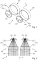
- the Figures 1 and 2 show a light module which is identified in its entirety with the reference number 10.
- the light module 10 is used in a motor vehicle headlight to generate a predeterminable overall light distribution in the light exit direction onto a roadway in front of the vehicle.
- the light module comprises a first sub-module 20a and a second sub-module 20b.
- the first sub-module 20a comprises a semiconductor light source 22a.
- the second sub-module 20b comprises a semiconductor light source 22b.
- the semiconductor light sources 22a, 22b comprise several light-emitting diodes, LEDs.
- the LEDs can be arranged in a matrix-like manner above and/or next to one another, so that they form an LED array.
- the LEDs of the semiconductor light sources 22a, 22b can advantageously be controlled individually, in groups or all together.
- first sub-module 20a and the second sub-module 20b each comprise an optical system 24a, 24b, each with a primary optics 26a, 26b for bundling at least a portion of the light from the semiconductor light sources 22a, 22b emitted light and a respective secondary optics 28a, 28b for projecting at least a portion of the bundled light as a first and second light distribution in the light exit direction 12 of the light module 10.
- the semiconductor light source 22a of the first sub-module is arranged in a wavelength-dependent focal point 30a of a first wavelength of the optical system 24a of the first sub-module 20a and the semiconductor light source 22b of the second sub-module 20b is arranged in a wavelength-dependent focal point 30b of a second wavelength of the optical system 24b of the second sub-module 20b.
- the first wavelength and the second wavelength differ from each other.
- the first sub-module 20a is designed for the first wavelength and the second sub-module is designed for the second wavelength.
- Design here means that the optical system 24a of the first sub-module 20a images the semiconductor light source 22a for the first wavelength and the optical system 24b of the second sub-module 20b images the semiconductor light source 22b for the second wavelength as sharply as possible.
- the Figures 3a and 3b each show a so-called spot diagram of the first and second sub-modules 20a, 20b for a central object point, ie for a point that lies on an intersection point of a plane of the respective semiconductor light source 22a, 22b and an optical axis of the respective optical system 24a, 24b.
- the spot diagram the impact points that emanate from the central object point are shown in the image plane.
- FIG 3a the spot diagram of the first sub-module 20a is shown. Rays of the first wavelength impinge on an area in the center of the diagram, while rays of the second wavelength impinge scattered around the area in the center, approximately in a radius of approximately 0.2 degrees.
- the impingement points of the rays of the first wavelength are marked by a cross.
- the impingement points of the rays of the second wavelength are marked by a square. Because the first sub-module 20a is designed for the first wavelength, the radius of the area in the center in which the rays of the first wavelength impinge is minimal. Since the optical system 24a comprises neither an achromat nor an apochromat, the imaging of rays of other wavelengths, for example the second wavelength, is not optimal.
- Light distributions that can be generated with the first sub-module 20a therefore include a color error, especially in the edge areas of the light distributions.
- Color error is understood to mean a deviation in the light color from a white point.
- a light distribution at a light-dark boundary in the area that is supposed to appear dark, a color fringe that is created by rays of the second wavelength.
- the proportion of rays of the second wavelength is again somewhat too low, so that here rays of the first wavelength determine the light color.
- This effect is also known as chromatic aberration.
- the chromatic aberration is not corrected by the first optical system 24a.
- an achromat or an apochromat would be necessary for this. This would in turn increase the number of components, in particular lenses, of the optical system 24a, and would therefore result in higher costs, a larger installation space required, greater weight and possibly lower optical efficiency.
- FIG 3b the spot diagram of the second sub-module 20b is shown. Rays of the second wavelength impinge on an area in the center of the diagram, while rays of the first wavelength impinge scattered at various points around the area in the center, approximately in a radius of approximately 0.2 degrees. The impingement points of the rays of the first wavelength are marked by a cross. The impingement points of the rays of the second wavelength are marked by a square. Because the second sub-module 20b is designed for the second wavelength, the radius of the area in the center in which the rays of the second wavelength impinge minimal. Since the optical system 24b also does not include an achromat or apochromat, the imaging of rays of other wavelengths, for example the first wavelength, is not optimal.
- Light distributions that can be generated with the second sub-module 20b therefore include a color error, particularly in the edge areas of the light distributions.
- a light distribution at a light-dark boundary in the area that should appear dark, includes a color fringe that is generated by rays of the first wavelength.
- the proportion of rays of the first wavelength is again somewhat too low, so that rays of the second wavelength determine the light color here.
- the chromatic aberration is also not corrected by the second optical system 24b.
- the color errors of the first light distribution of the first sub-module 20a and the second light distribution of the second sub-module 20b can be corrected by superimposing the two light distributions.
- the first light distribution of the first sub-module 20a and the second light distribution of the second sub-module 20b overlap at least partially, in particular largely. It can also prove advantageous if the illumination areas of the first and second sub-modules 20a, 20b are identical, so that at least the first and second light distributions completely overlap.
- the first wavelength is, for example, 500 nm and the second wavelength is, for example, 570 nm.
- the first light distribution includes a blue color fringe at the light-dark boundary, in the area that should appear dark, and a warm white to yellow light color in the area at the light-dark boundary that should appear light.
- the second light distribution includes a yellow color fringe at the light-dark boundary, in the area that should appear dark, and a cold white to blue light color in the area at the light-dark boundary that should appear light.
- the yellow and blue color fringe overlap at the light-dark boundary, in the area that should appear dark, and the cold white to blue light color and the warm white to yellow light color overlap in the area that should appear light, so that the overall light distribution includes a white light color.
- the color of the overall light distribution of the light module 10 can be significantly reduced.
- the overall light distribution that can be generated with the light module 10 does not include a hard white contrast at the light-dark boundary.
- a hard white contrast is usually not desired in motor vehicle headlights. Often, additional effort is even made to increase the contrast at the light-dark boundary, for example via so-called Microstructuring of lens surfaces or frosting. In the light module 10 according to the invention, such measures are not necessary.
- a suitable design of the sub-modules 20a, 20b of the light module 10 can produce a sufficiently color-neutral overall light distribution and at the same time avoid a hard white contrast at the light-dark boundary. Achromats or apochromats and additional microstructuring or frosting of the lens surfaces can be dispensed with. This advantageously minimizes costs, weight and installation space. At the same time, the optical efficiency can be increased with a suitable choice of material and design, since the absorption is reduced by a smaller required number of lenses or lens surfaces and thus fewer losses occur due to Fresnel reflection.
- beam paths 32a, 32b of the first and second sub-modules 20a, 20b are shown for the respective wavelength for which the sub-modules 20a, 20b are designed.
- the beam paths 32a, 32b each originate from a respective center of the respective semiconductor light source 22a, 22b located at the focal point 30a, 30b and are captured and imaged by the optical systems 24a, 24b.
- the representation of the beam paths arranged side by side is merely an example.
- the beam paths 32a, 32b overlap to form an overall light distribution of the light module 10.
- the beams emanating from the semiconductor light sources 22a, 22b have a high divergence.
- the semiconductor light sources 22a, 22b each radiate into the entire half-space.
- the numerical apparatus is proportional to the sine of the opening angle. If the semiconductor light sources 22a, 22b are Lambert radiators, the optical efficiency of the optical systems 24a, 24b is in turn proportional to the square of the numerical aperture. Consequently, the efficiency is proportional to the square of the sine of the opening angle. Consequently, it is very advantageous for the efficiency of the described light module 10 if the numerical aperture of the optical systems 24a, 24b is as high as possible.
- the numerical aperture of the optical systems 24a, 24b is at least 0.5, in particular 0.65.
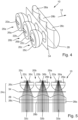
- Figures 4, 5 and 6 show various representations of another embodiment of a light module 10.
- the light module 10 comprises a further sub-module 20c.
- the sub-module 20c is in principle analogous to the already described
- Sub-modules 20a, 20b are constructed and advantageously designed for a third wavelength.
- the third wavelength differs from the first and the second wavelength.
- the light module in the Figures 4, 5 and 6 a cover 34.
- the cover 34 is designed as a single piece for the three sub-modules 20a, 20b, 20c.
- each sub-module 20a, 20b, 20c comprises a separate cover.
- the secondary optics 28a, 28b, 28c of the optical systems 24a, 24b, 24c of the sub-modules 20a, 20b, 20c are designed as a one-piece secondary optics 28.
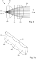
- the one-piece secondary optics 28 is also designed as an anamorphic lens. This is shown in Figures 7a and 7b shown.
- Figure 7a shows the anamorphic lens 28 from the light entrance side and Figure 7b from the light exit side.
- light entry surfaces 36a, 36b, 36c each comprise a cylindrical surface section with a vertical axis of rotation.
- the light exit surface 38 comprises a cylindrical surface section with a horizontal axis of rotation, in particular aligned perpendicular to the light exit direction 12.
- the light entry surfaces 36a, 36b, 36c are designed such that incoming light rays are bundled in the horizontal plane, cf. Fig. 5 .
- the light exit surface 38 is advantageously designed so that emerging light rays are bundled in the vertical plane, cf. Fig. 6 .
- the one-piece secondary optics 28 reduces the number of components required and thus the tolerances to be observed with regard to positioning and costs. Furthermore, the particularly one-piece, cylindrical shape of the light exit surface 38 can have a beneficial effect on the aesthetic appearance of the light module 10.
- Figure 8 a motor vehicle headlight 40.
- the headlight 40 comprises a housing 42, which is made of plastic, for example.
- the housing 42 has a light exit opening 44 in the light exit direction 12, which is closed by a transparent cover plate 46.
- a light module 10 according to the invention is arranged inside the housing 42.
- the light module 10 serves to generate any resulting driving light distribution of the motor vehicle headlight or a part thereof, for example a dipped beam, high beam, adaptive driving light (city light, country road light, motorway light, partial high beam, marker light), fog light or the like.
- the housing can accommodate 42
- Other light modules can also be arranged to generate any desired driving light distribution or part thereof, or light modules to implement any desired lighting function (e.g. indicator light, position light, parking light, daytime running light, parking light, reversing light, brake light or similar).
Landscapes
- Engineering & Computer Science (AREA)
- General Engineering & Computer Science (AREA)
- Physics & Mathematics (AREA)
- Optics & Photonics (AREA)
- General Physics & Mathematics (AREA)
- Microelectronics & Electronic Packaging (AREA)
- Mechanical Engineering (AREA)
- Non-Portable Lighting Devices Or Systems Thereof (AREA)
Claims (12)
- Module d'éclairage (10) pour un phare de véhicule automobile (40) permettant de générer une distribution de lumière globale, dans lequel le module d'éclairage (10) comprend un premier sous-module (20a) permettant de générer une première distribution de lumière et au moins un autre, deuxième sous-module (20b) permettant de générer une deuxième distribution de lumière, dans lequel le premier et le deuxième sous-module (20a, 20b) comprennent respectivement au moins une source de lumière à semi-conducteur (22a, 22b) comportant une surface émettrice de lumière permettant d'émettre de la lumière et un système optique (24a, 24b) comportant une optique primaire (26a, 26b) permettant de concentrer au moins une partie de la lumière émise et une optique secondaire (28, 28a, 28b) permettant de projeter au moins une partie de la lumière concentrée dans une direction de sortie de lumière (12) du module d'éclairage (10), dans lequel la distribution de lumière globale du module d'éclairage (10) comprend la superposition de la première distribution de lumière à la deuxième distribution de lumière, et la source de lumière à semi-conducteur (22a) du premier sous-module (20a) est disposée dans un point focal (30a) dépendant de la longueur d'onde d'une première longueur d'onde du système optique (24a) du premier sous-module (20a), de sorte que le premier sous-module (20a) est configuré pour la première longueur d'onde et représente nettement des rayons de la première longueur d'onde, et la source de lumière à semi-conducteur (22b) du deuxième sous-module (20b) est disposée dans un point focal (30b) dépendant de la longueur d'onde d'une deuxième longueur d'onde du système optique (24b) du deuxième sous-module (20b), de sorte que le deuxième sous-module (20b) est configuré pour la deuxième longueur d'onde et représente nettement des rayons de la deuxième longueur d'onde, dans lequel la première longueur d'onde est différente de la deuxième longueur d'onde,
caractérisé en ce qu'une aberration chromatique provoquée par des rayons de la deuxième longueur d'onde dans la première distribution de lumière du premier sous-module (20a) et une aberration chromatique provoquée par des rayons de la première longueur d'onde dans la deuxième distribution de lumière sont annulées par la superposition de la première distribution de lumière à la deuxième distribution de lumière dans la distribution de lumière globale du module d'éclairage. - Module d'éclairage (10) selon la revendication 1, caractérisé en ce que la première distribution de lumière du premier sous-module (20a) et la deuxième distribution de lumière du deuxième sous-module (20b) se superposent au moins partiellement, en particulier en grande partie.
- Module d'éclairage (10) selon l'une des revendications précédentes, caractérisé en ce que la source de lumière à semi-conducteur (22a) du premier sous-module (20a) et/ou la source de lumière à semi-conducteur (22b) du deuxième sous-module (20b) comprennent au moins une, en particulier plusieurs, diodes électroluminescentes.
- Module d'éclairage (10) selon l'une des revendications précédentes, caractérisé en ce qu'une ouverture numérique du système optique (24a, 24b) du premier et/ou du deuxième sous-module (20a, 20b) est d'au moins 0,5, en particulier d'au moins 0,65.
- Module d'éclairage (10) selon l'une des revendications précédentes, caractérisé en ce que l'optique secondaire (28, 28a) du premier sous-module (20a) et l'optique secondaire (28, 28b) du deuxième sous-module (20b) sont réalisées d'une seule pièce.
- Module d'éclairage (10) selon l'une des revendications précédentes, caractérisé en ce que l'optique secondaire (28, 28a) du premier sous-module (20a) et/ou l'optique secondaire (28, 28b) du deuxième sous-module (20b) sont réalisées sous forme de lentille anamorphosante (28).
- Module d'éclairage (10) selon la revendication 6,
caractérisé en ce qu'au moins une surface d'entrée de lumière (36a, 36b, 36c) de la lentille anamorphosante (28) est réalisée sous forme de section de surface cylindrique comportant un axe de rotation horizontal et au moins une surface de sortie de lumière (38) de la lentille anamorphosante (28) est réalisée sous forme de section de surface cylindrique comportant un axe de rotation vertical. - Module d'éclairage (10) selon l'une des revendications précédentes, caractérisé en ce que le premier sous-module (20a) et/ou le deuxième sous-module (20b) comprennent un écran (34).
- Module d'éclairage (10) selon la revendication 8, caractérisé en ce que l'écran (23) du premier sous-module (20a) et du deuxième sous-module (20b) est réalisé d'une seule pièce.
- Module d'éclairage (10) selon l'une des revendications précédentes, caractérisé en ce que le module d'éclairage (10) comprend un troisième sous-module (20c) permettant de générer une troisième distribution de lumière comportant au moins une source de lumière à semi-conducteur (22c) comportant une surface émettrice de lumière permettant d'émettre de la lumière et un système optique (24c) comportant une optique primaire (26c) permettant de concentrer au moins une partie de la lumière émise et une optique secondaire (28c) permettant de projeter au moins une partie de la lumière concentrée dans une direction de sortie de lumière (12) du module d'éclairage (10), dans lequel la distribution de lumière globale du module d'éclairage (10) comprend une superposition de la troisième distribution de lumière, dans lequel la source de lumière à semi-conducteur (22c) est disposée dans un point focal (30c) dépendant de la longueur d'onde d'une troisième longueur d'onde du système optique (24c) du troisième sous-module (20c), dans lequel la troisième longueur d'onde est différente de la première et/ou de la deuxième longueur d'onde.
- Module d'éclairage (10) selon l'une des revendications précédentes, caractérisé en ce que la première longueur d'onde est d'environ 500 nm et/ou la deuxième longueur d'onde est d'environ 570 nm et/ou la troisième longueur d'onde est d'environ 470 nm.
- Phare de véhicule automobile (40) comprenant au moins un module d'éclairage (10), caractérisé en ce que le module d'éclairage (10) est réalisé selon au moins l'une des revendications 1 à 11.
Applications Claiming Priority (1)
| Application Number | Priority Date | Filing Date | Title |
|---|---|---|---|
| DE102020132350.6A DE102020132350A1 (de) | 2020-12-04 | 2020-12-04 | Lichtmodul für einen Kraftfahrzeugscheinwerfer |
Publications (2)
| Publication Number | Publication Date |
|---|---|
| EP4008951A1 EP4008951A1 (fr) | 2022-06-08 |
| EP4008951B1 true EP4008951B1 (fr) | 2025-03-05 |
Family
ID=78821393
Family Applications (1)
| Application Number | Title | Priority Date | Filing Date |
|---|---|---|---|
| EP21212019.0A Active EP4008951B1 (fr) | 2020-12-04 | 2021-12-02 | Module lumineux pour un phare de véhicule automobile |
Country Status (3)
| Country | Link |
|---|---|
| EP (1) | EP4008951B1 (fr) |
| CN (1) | CN114607979A (fr) |
| DE (1) | DE102020132350A1 (fr) |
Families Citing this family (2)
| Publication number | Priority date | Publication date | Assignee | Title |
|---|---|---|---|---|
| CN117628431A (zh) * | 2022-08-12 | 2024-03-01 | 巨铠精密工业股份有限公司 | 多光源照明模块及其汽车灯具 |
| US12449106B2 (en) | 2022-09-23 | 2025-10-21 | Autosystems, A Division Of Magna Exteriors Inc. | Vehicle headlight assembly and system with hybrid matrix low beam |
Family Cites Families (11)
| Publication number | Priority date | Publication date | Assignee | Title |
|---|---|---|---|---|
| US20080055896A1 (en) | 2006-08-30 | 2008-03-06 | David Charles Feldmeier | Systems, devices, components and methods for controllably configuring the color of light emitted by an automotive LED illumination system |
| DE102009053581B3 (de) * | 2009-10-05 | 2011-03-03 | Automotive Lighting Reutlingen Gmbh | Lichtmodul für eine Beleuchtungseinrichtung eines Kraftfahrzeugs |
| DE102010029176A1 (de) * | 2009-10-05 | 2012-12-27 | Automotive Lighting Reutlingen Gmbh | Kraftfahrzeugscheinwerfer mit einem Halbleiterlichtquellen, eine Primäroptik und eine Sekundäroptik aufweisenden Lichtmodul |
| JP5516854B2 (ja) * | 2009-10-08 | 2014-06-11 | スタンレー電気株式会社 | 車両用灯具 |
| DE102011075510A1 (de) * | 2011-05-09 | 2012-11-15 | Automotive Lighting Reutlingen Gmbh | Lichtmodul für einen Kraftfahrzeugscheinwerfer zur Erzeugung einer variablen Lichtverteilung und Kraftfahrzeugscheinwerfer mit einem solchen Lichtmodul |
| US8733992B2 (en) * | 2012-10-01 | 2014-05-27 | Osram Sylvania, Inc. | LED low profile linear front fog module |
| DE102014210500A1 (de) * | 2014-06-03 | 2015-12-03 | Osram Gmbh | Optik für eine Fahrzeug-Beleuchtungseinrichtung |
| KR102289753B1 (ko) * | 2014-12-24 | 2021-08-13 | 에스엘 주식회사 | 적응형 드라이빙 빔 모듈 |
| JP6600987B2 (ja) * | 2015-05-21 | 2019-11-06 | 市光工業株式会社 | 車両用灯具 |
| KR102392548B1 (ko) | 2017-12-29 | 2022-04-29 | 에스엘 주식회사 | 차량용 광학계 및 이를 이용한 차량용 램프 |
| EP3608585A1 (fr) * | 2018-08-07 | 2020-02-12 | ZKW Group GmbH | Dispositif de projection d'un grand nombre de systèmes micro-optiques et module d'éclairage de phare de véhicule automobile |
-
2020
- 2020-12-04 DE DE102020132350.6A patent/DE102020132350A1/de active Pending
-
2021
- 2021-12-02 EP EP21212019.0A patent/EP4008951B1/fr active Active
- 2021-12-02 CN CN202111457991.2A patent/CN114607979A/zh active Pending
Also Published As
| Publication number | Publication date |
|---|---|
| CN114607979A (zh) | 2022-06-10 |
| DE102020132350A1 (de) | 2022-06-09 |
| EP4008951A1 (fr) | 2022-06-08 |
Similar Documents
| Publication | Publication Date | Title |
|---|---|---|
| EP3864341B1 (fr) | Phare à feu de croisement | |
| EP2799761B1 (fr) | Module d'éclairage de phare de véhicule automobile | |
| EP2910847B1 (fr) | Module d'éclairage d'un projecteur de véhicule automobile et projecteur avec un tel module d'éclairage | |
| DE102011078653B4 (de) | Vorsatzoptik zur Bündelung von ausgesandtem Licht mindestens einer Halbleiterlichtquelle | |
| DE102009008631B4 (de) | Projektionsmodul für einen Kraftfahrzeugscheinwerfer | |
| DE102009053581B3 (de) | Lichtmodul für eine Beleuchtungseinrichtung eines Kraftfahrzeugs | |
| EP3014171B1 (fr) | Phare de véhicule | |
| EP1818599B1 (fr) | Feu de croisement, produisant une coupure à contraste importante | |
| EP2420728B1 (fr) | Phare avec gradient d'intensité lumineuse ciblée amortie sur la limite de clair-obscur | |
| DE102021122953B3 (de) | Beleuchtungsvorrichtung für ein Kraftfahrzeug | |
| DE102009037698A1 (de) | Fahrzeugbeleuchtungseinheit und Fahrzeugleuchte | |
| DE102012208566A1 (de) | Beleuchtungsvorrichtung für ein Kraftfahrzeug | |
| DE102013226624A1 (de) | Beleuchtungseinrichtung | |
| WO2011154470A1 (fr) | Accessoire optique constitué d'un matériau transparent pour la focalisation de lumière, ensemble de lentilles comportant au moins un tel accessoire optique, et module de lumière doté d'un tel ensemble de lentilles | |
| WO2020030573A1 (fr) | Dispositif de projection, module d'éclairage et projecteur de véhicule à moteur composé de micro-optiques | |
| DE102019218776B4 (de) | Leuchte für Fahrzeug | |
| EP4008951B1 (fr) | Module lumineux pour un phare de véhicule automobile | |
| DE102016213380A1 (de) | Optisches element und beleuchtungsvorrichtung | |
| WO2016059180A1 (fr) | Dispositif d'éclairage pourvu d'un écran comportant une pluralité d'ouvertures | |
| DE102021107851B4 (de) | Fahrzeugleuchte und fahrzeug | |
| DE102016118152A1 (de) | Lichtmodul für einen Kraftfahrzeugscheinwerfer | |
| EP2837962A1 (fr) | Procédé destiné à calculer des surfaces de lentilles optiques et lentille de projection calculée selon le procédé pour un module d'éclairage d'un phare de véhicule automobile | |
| DE102015219211B4 (de) | Lichtmodul für eine Kfz-Beleuchtungseinrichtung | |
| DE102012215124B4 (de) | Beleuchtungseinrichtung mit mehreren Lichtquellen und Lichtleitkörpern sowie einem Reflektor | |
| DE102018105720B4 (de) | Lichtmodul für Kraftfahrzeugscheinwerfer |
Legal Events
| Date | Code | Title | Description |
|---|---|---|---|
| PUAI | Public reference made under article 153(3) epc to a published international application that has entered the european phase |
Free format text: ORIGINAL CODE: 0009012 |
|
| STAA | Information on the status of an ep patent application or granted ep patent |
Free format text: STATUS: THE APPLICATION HAS BEEN PUBLISHED |
|
| AK | Designated contracting states |
Kind code of ref document: A1 Designated state(s): AL AT BE BG CH CY CZ DE DK EE ES FI FR GB GR HR HU IE IS IT LI LT LU LV MC MK MT NL NO PL PT RO RS SE SI SK SM TR |
|
| STAA | Information on the status of an ep patent application or granted ep patent |
Free format text: STATUS: REQUEST FOR EXAMINATION WAS MADE |
|
| 17P | Request for examination filed |
Effective date: 20221026 |
|
| RBV | Designated contracting states (corrected) |
Designated state(s): AL AT BE BG CH CY CZ DE DK EE ES FI FR GB GR HR HU IE IS IT LI LT LU LV MC MK MT NL NO PL PT RO RS SE SI SK SM TR |
|
| STAA | Information on the status of an ep patent application or granted ep patent |
Free format text: STATUS: EXAMINATION IS IN PROGRESS |
|
| 17Q | First examination report despatched |
Effective date: 20230302 |
|
| GRAP | Despatch of communication of intention to grant a patent |
Free format text: ORIGINAL CODE: EPIDOSNIGR1 |
|
| STAA | Information on the status of an ep patent application or granted ep patent |
Free format text: STATUS: GRANT OF PATENT IS INTENDED |
|
| INTG | Intention to grant announced |
Effective date: 20240903 |
|
| GRAS | Grant fee paid |
Free format text: ORIGINAL CODE: EPIDOSNIGR3 |
|
| GRAA | (expected) grant |
Free format text: ORIGINAL CODE: 0009210 |
|
| STAA | Information on the status of an ep patent application or granted ep patent |
Free format text: STATUS: THE PATENT HAS BEEN GRANTED |
|
| RAP3 | Party data changed (applicant data changed or rights of an application transferred) |
Owner name: MARELLI GERMANY GMBH |
|
| P01 | Opt-out of the competence of the unified patent court (upc) registered |
Free format text: CASE NUMBER: APP_1974/2025 Effective date: 20250113 |
|
| AK | Designated contracting states |
Kind code of ref document: B1 Designated state(s): AL AT BE BG CH CY CZ DE DK EE ES FI FR GB GR HR HU IE IS IT LI LT LU LV MC MK MT NL NO PL PT RO RS SE SI SK SM TR |
|
| REG | Reference to a national code |
Ref country code: GB Ref legal event code: FG4D Free format text: NOT ENGLISH |
|
| REG | Reference to a national code |
Ref country code: CH Ref legal event code: EP |
|
| REG | Reference to a national code |
Ref country code: IE Ref legal event code: FG4D Free format text: LANGUAGE OF EP DOCUMENT: GERMAN |
|
| REG | Reference to a national code |
Ref country code: DE Ref legal event code: R096 Ref document number: 502021006850 Country of ref document: DE |
|
| PG25 | Lapsed in a contracting state [announced via postgrant information from national office to epo] |
Ref country code: RS Free format text: LAPSE BECAUSE OF FAILURE TO SUBMIT A TRANSLATION OF THE DESCRIPTION OR TO PAY THE FEE WITHIN THE PRESCRIBED TIME-LIMIT Effective date: 20250605 |
|
| PG25 | Lapsed in a contracting state [announced via postgrant information from national office to epo] |
Ref country code: FI Free format text: LAPSE BECAUSE OF FAILURE TO SUBMIT A TRANSLATION OF THE DESCRIPTION OR TO PAY THE FEE WITHIN THE PRESCRIBED TIME-LIMIT Effective date: 20250305 |
|
| REG | Reference to a national code |
Ref country code: NL Ref legal event code: MP Effective date: 20250305 |
|
| PG25 | Lapsed in a contracting state [announced via postgrant information from national office to epo] |
Ref country code: ES Free format text: LAPSE BECAUSE OF FAILURE TO SUBMIT A TRANSLATION OF THE DESCRIPTION OR TO PAY THE FEE WITHIN THE PRESCRIBED TIME-LIMIT Effective date: 20250305 |
|
| REG | Reference to a national code |
Ref country code: LT Ref legal event code: MG9D |
|
| PG25 | Lapsed in a contracting state [announced via postgrant information from national office to epo] |
Ref country code: NO Free format text: LAPSE BECAUSE OF FAILURE TO SUBMIT A TRANSLATION OF THE DESCRIPTION OR TO PAY THE FEE WITHIN THE PRESCRIBED TIME-LIMIT Effective date: 20250605 |
|
| PG25 | Lapsed in a contracting state [announced via postgrant information from national office to epo] |
Ref country code: HR Free format text: LAPSE BECAUSE OF FAILURE TO SUBMIT A TRANSLATION OF THE DESCRIPTION OR TO PAY THE FEE WITHIN THE PRESCRIBED TIME-LIMIT Effective date: 20250305 |
|
| PG25 | Lapsed in a contracting state [announced via postgrant information from national office to epo] |
Ref country code: LV Free format text: LAPSE BECAUSE OF FAILURE TO SUBMIT A TRANSLATION OF THE DESCRIPTION OR TO PAY THE FEE WITHIN THE PRESCRIBED TIME-LIMIT Effective date: 20250305 |
|
| PG25 | Lapsed in a contracting state [announced via postgrant information from national office to epo] |
Ref country code: GR Free format text: LAPSE BECAUSE OF FAILURE TO SUBMIT A TRANSLATION OF THE DESCRIPTION OR TO PAY THE FEE WITHIN THE PRESCRIBED TIME-LIMIT Effective date: 20250606 Ref country code: BG Free format text: LAPSE BECAUSE OF FAILURE TO SUBMIT A TRANSLATION OF THE DESCRIPTION OR TO PAY THE FEE WITHIN THE PRESCRIBED TIME-LIMIT Effective date: 20250305 |
|
| PG25 | Lapsed in a contracting state [announced via postgrant information from national office to epo] |
Ref country code: NL Free format text: LAPSE BECAUSE OF FAILURE TO SUBMIT A TRANSLATION OF THE DESCRIPTION OR TO PAY THE FEE WITHIN THE PRESCRIBED TIME-LIMIT Effective date: 20250305 |
|
| PG25 | Lapsed in a contracting state [announced via postgrant information from national office to epo] |
Ref country code: SE Free format text: LAPSE BECAUSE OF FAILURE TO SUBMIT A TRANSLATION OF THE DESCRIPTION OR TO PAY THE FEE WITHIN THE PRESCRIBED TIME-LIMIT Effective date: 20250305 |
|
| PG25 | Lapsed in a contracting state [announced via postgrant information from national office to epo] |
Ref country code: SM Free format text: LAPSE BECAUSE OF FAILURE TO SUBMIT A TRANSLATION OF THE DESCRIPTION OR TO PAY THE FEE WITHIN THE PRESCRIBED TIME-LIMIT Effective date: 20250305 |
|
| PG25 | Lapsed in a contracting state [announced via postgrant information from national office to epo] |
Ref country code: PT Free format text: LAPSE BECAUSE OF FAILURE TO SUBMIT A TRANSLATION OF THE DESCRIPTION OR TO PAY THE FEE WITHIN THE PRESCRIBED TIME-LIMIT Effective date: 20250707 |
|
| PG25 | Lapsed in a contracting state [announced via postgrant information from national office to epo] |
Ref country code: IT Free format text: LAPSE BECAUSE OF FAILURE TO SUBMIT A TRANSLATION OF THE DESCRIPTION OR TO PAY THE FEE WITHIN THE PRESCRIBED TIME-LIMIT Effective date: 20250305 Ref country code: PL Free format text: LAPSE BECAUSE OF FAILURE TO SUBMIT A TRANSLATION OF THE DESCRIPTION OR TO PAY THE FEE WITHIN THE PRESCRIBED TIME-LIMIT Effective date: 20250305 |
|
| PG25 | Lapsed in a contracting state [announced via postgrant information from national office to epo] |
Ref country code: EE Free format text: LAPSE BECAUSE OF FAILURE TO SUBMIT A TRANSLATION OF THE DESCRIPTION OR TO PAY THE FEE WITHIN THE PRESCRIBED TIME-LIMIT Effective date: 20250305 Ref country code: CZ Free format text: LAPSE BECAUSE OF FAILURE TO SUBMIT A TRANSLATION OF THE DESCRIPTION OR TO PAY THE FEE WITHIN THE PRESCRIBED TIME-LIMIT Effective date: 20250305 |
|
| PG25 | Lapsed in a contracting state [announced via postgrant information from national office to epo] |
Ref country code: RO Free format text: LAPSE BECAUSE OF FAILURE TO SUBMIT A TRANSLATION OF THE DESCRIPTION OR TO PAY THE FEE WITHIN THE PRESCRIBED TIME-LIMIT Effective date: 20250305 |
|
| PG25 | Lapsed in a contracting state [announced via postgrant information from national office to epo] |
Ref country code: SK Free format text: LAPSE BECAUSE OF FAILURE TO SUBMIT A TRANSLATION OF THE DESCRIPTION OR TO PAY THE FEE WITHIN THE PRESCRIBED TIME-LIMIT Effective date: 20250305 |
|
| PG25 | Lapsed in a contracting state [announced via postgrant information from national office to epo] |
Ref country code: IS Free format text: LAPSE BECAUSE OF FAILURE TO SUBMIT A TRANSLATION OF THE DESCRIPTION OR TO PAY THE FEE WITHIN THE PRESCRIBED TIME-LIMIT Effective date: 20250705 |
|
| REG | Reference to a national code |
Ref country code: DE Ref legal event code: R097 Ref document number: 502021006850 Country of ref document: DE |
|
| PGFP | Annual fee paid to national office [announced via postgrant information from national office to epo] |
Ref country code: DE Payment date: 20251126 Year of fee payment: 5 |
|
| PLBE | No opposition filed within time limit |
Free format text: ORIGINAL CODE: 0009261 |
|
| STAA | Information on the status of an ep patent application or granted ep patent |
Free format text: STATUS: NO OPPOSITION FILED WITHIN TIME LIMIT |
|
| PG25 | Lapsed in a contracting state [announced via postgrant information from national office to epo] |
Ref country code: DK Free format text: LAPSE BECAUSE OF FAILURE TO SUBMIT A TRANSLATION OF THE DESCRIPTION OR TO PAY THE FEE WITHIN THE PRESCRIBED TIME-LIMIT Effective date: 20250305 |
|
| PGFP | Annual fee paid to national office [announced via postgrant information from national office to epo] |
Ref country code: AT Payment date: 20260113 Year of fee payment: 5 |
|
| REG | Reference to a national code |
Ref country code: CH Ref legal event code: L10 Free format text: ST27 STATUS EVENT CODE: U-0-0-L10-L00 (AS PROVIDED BY THE NATIONAL OFFICE) Effective date: 20260114 |
|
| PGFP | Annual fee paid to national office [announced via postgrant information from national office to epo] |
Ref country code: FR Payment date: 20251120 Year of fee payment: 5 |
|
| 26N | No opposition filed |
Effective date: 20251208 |