EP4008973B1 - Climatiseur - Google Patents
Climatiseur Download PDFInfo
- Publication number
- EP4008973B1 EP4008973B1 EP20882824.4A EP20882824A EP4008973B1 EP 4008973 B1 EP4008973 B1 EP 4008973B1 EP 20882824 A EP20882824 A EP 20882824A EP 4008973 B1 EP4008973 B1 EP 4008973B1
- Authority
- EP
- European Patent Office
- Prior art keywords
- port
- pipe
- piping
- refrigerant
- heat exchanger
- Prior art date
- Legal status (The legal status is an assumption and is not a legal conclusion. Google has not performed a legal analysis and makes no representation as to the accuracy of the status listed.)
- Active
Links
Images



Classifications
-
- F—MECHANICAL ENGINEERING; LIGHTING; HEATING; WEAPONS; BLASTING
- F25—REFRIGERATION OR COOLING; COMBINED HEATING AND REFRIGERATION SYSTEMS; HEAT PUMP SYSTEMS; MANUFACTURE OR STORAGE OF ICE; LIQUEFACTION SOLIDIFICATION OF GASES
- F25B—REFRIGERATION MACHINES, PLANTS OR SYSTEMS; COMBINED HEATING AND REFRIGERATION SYSTEMS; HEAT PUMP SYSTEMS
- F25B13/00—Compression machines, plants or systems, with reversible cycle
-
- F—MECHANICAL ENGINEERING; LIGHTING; HEATING; WEAPONS; BLASTING
- F24—HEATING; RANGES; VENTILATING
- F24F—AIR-CONDITIONING; AIR-HUMIDIFICATION; VENTILATION; USE OF AIR CURRENTS FOR SCREENING
- F24F3/00—Air-conditioning systems in which conditioned primary air is supplied from one or more central stations to distributing units in the rooms or spaces where it may receive secondary treatment; Apparatus specially designed for such systems
- F24F3/06—Air-conditioning systems in which conditioned primary air is supplied from one or more central stations to distributing units in the rooms or spaces where it may receive secondary treatment; Apparatus specially designed for such systems characterised by the arrangements for the supply of heat-exchange fluid for the subsequent treatment of primary air in the room units
-
- F—MECHANICAL ENGINEERING; LIGHTING; HEATING; WEAPONS; BLASTING
- F25—REFRIGERATION OR COOLING; COMBINED HEATING AND REFRIGERATION SYSTEMS; HEAT PUMP SYSTEMS; MANUFACTURE OR STORAGE OF ICE; LIQUEFACTION SOLIDIFICATION OF GASES
- F25B—REFRIGERATION MACHINES, PLANTS OR SYSTEMS; COMBINED HEATING AND REFRIGERATION SYSTEMS; HEAT PUMP SYSTEMS
- F25B41/00—Fluid-circulation arrangements
- F25B41/20—Disposition of valves, e.g. of on-off valves or flow control valves
-
- F—MECHANICAL ENGINEERING; LIGHTING; HEATING; WEAPONS; BLASTING
- F25—REFRIGERATION OR COOLING; COMBINED HEATING AND REFRIGERATION SYSTEMS; HEAT PUMP SYSTEMS; MANUFACTURE OR STORAGE OF ICE; LIQUEFACTION SOLIDIFICATION OF GASES
- F25B—REFRIGERATION MACHINES, PLANTS OR SYSTEMS; COMBINED HEATING AND REFRIGERATION SYSTEMS; HEAT PUMP SYSTEMS
- F25B41/00—Fluid-circulation arrangements
- F25B41/40—Fluid line arrangements
-
- F—MECHANICAL ENGINEERING; LIGHTING; HEATING; WEAPONS; BLASTING
- F25—REFRIGERATION OR COOLING; COMBINED HEATING AND REFRIGERATION SYSTEMS; HEAT PUMP SYSTEMS; MANUFACTURE OR STORAGE OF ICE; LIQUEFACTION SOLIDIFICATION OF GASES
- F25B—REFRIGERATION MACHINES, PLANTS OR SYSTEMS; COMBINED HEATING AND REFRIGERATION SYSTEMS; HEAT PUMP SYSTEMS
- F25B2313/00—Compression machines, plants or systems with reversible cycle not otherwise provided for
- F25B2313/023—Compression machines, plants or systems with reversible cycle not otherwise provided for using multiple indoor units
- F25B2313/0233—Compression machines, plants or systems with reversible cycle not otherwise provided for using multiple indoor units in parallel arrangements
-
- F—MECHANICAL ENGINEERING; LIGHTING; HEATING; WEAPONS; BLASTING
- F25—REFRIGERATION OR COOLING; COMBINED HEATING AND REFRIGERATION SYSTEMS; HEAT PUMP SYSTEMS; MANUFACTURE OR STORAGE OF ICE; LIQUEFACTION SOLIDIFICATION OF GASES
- F25B—REFRIGERATION MACHINES, PLANTS OR SYSTEMS; COMBINED HEATING AND REFRIGERATION SYSTEMS; HEAT PUMP SYSTEMS
- F25B2313/00—Compression machines, plants or systems with reversible cycle not otherwise provided for
- F25B2313/027—Compression machines, plants or systems with reversible cycle not otherwise provided for characterised by the reversing means
- F25B2313/0272—Compression machines, plants or systems with reversible cycle not otherwise provided for characterised by the reversing means using bridge circuits of one-way valves
-
- F—MECHANICAL ENGINEERING; LIGHTING; HEATING; WEAPONS; BLASTING
- F25—REFRIGERATION OR COOLING; COMBINED HEATING AND REFRIGERATION SYSTEMS; HEAT PUMP SYSTEMS; MANUFACTURE OR STORAGE OF ICE; LIQUEFACTION SOLIDIFICATION OF GASES
- F25B—REFRIGERATION MACHINES, PLANTS OR SYSTEMS; COMBINED HEATING AND REFRIGERATION SYSTEMS; HEAT PUMP SYSTEMS
- F25B2400/00—Component parts or details not otherwise provided for in this subclass
- F25B2400/13—Economisers
-
- F—MECHANICAL ENGINEERING; LIGHTING; HEATING; WEAPONS; BLASTING
- F25—REFRIGERATION OR COOLING; COMBINED HEATING AND REFRIGERATION SYSTEMS; HEAT PUMP SYSTEMS; MANUFACTURE OR STORAGE OF ICE; LIQUEFACTION SOLIDIFICATION OF GASES
- F25B—REFRIGERATION MACHINES, PLANTS OR SYSTEMS; COMBINED HEATING AND REFRIGERATION SYSTEMS; HEAT PUMP SYSTEMS
- F25B2500/00—Problems to be solved
- F25B2500/12—Sound
-
- F—MECHANICAL ENGINEERING; LIGHTING; HEATING; WEAPONS; BLASTING
- F25—REFRIGERATION OR COOLING; COMBINED HEATING AND REFRIGERATION SYSTEMS; HEAT PUMP SYSTEMS; MANUFACTURE OR STORAGE OF ICE; LIQUEFACTION SOLIDIFICATION OF GASES
- F25B—REFRIGERATION MACHINES, PLANTS OR SYSTEMS; COMBINED HEATING AND REFRIGERATION SYSTEMS; HEAT PUMP SYSTEMS
- F25B2600/00—Control issues
- F25B2600/25—Control of valves
- F25B2600/2509—Economiser valves
-
- F—MECHANICAL ENGINEERING; LIGHTING; HEATING; WEAPONS; BLASTING
- F25—REFRIGERATION OR COOLING; COMBINED HEATING AND REFRIGERATION SYSTEMS; HEAT PUMP SYSTEMS; MANUFACTURE OR STORAGE OF ICE; LIQUEFACTION SOLIDIFICATION OF GASES
- F25B—REFRIGERATION MACHINES, PLANTS OR SYSTEMS; COMBINED HEATING AND REFRIGERATION SYSTEMS; HEAT PUMP SYSTEMS
- F25B2600/00—Control issues
- F25B2600/25—Control of valves
- F25B2600/2515—Flow valves
Definitions
- the present invention relates to the technical field of air conditioning, and in particular to an air conditioner.
- the enhanced vapor injection refrigerant system is more and more widely used, especially applications to the coal-to-electricity conversion and multi-split air conditioners in northern China.
- many systems are provided with secondary subcoolers to reduce pipeline pressure loss and indoor machine throttling noise.
- an economizer may be shared.
- EP 2 357 427 A1 discloses an air conditioner according to the preamble of claim 1.
- a main objective of the present invention is to provide an air conditioner which aims to enable the air conditioner to have a high heating capacity in low-temperature environments while having a thermostatic dehumidification function.
- the air conditioner provided in the present invention is defined in claim 1. It includes an outdoor unit and an indoor unit, where the outdoor unit includes an enhanced vapor compression mechanism and an outdoor heat exchanger, and the indoor unit includes a first heat exchanger and a first throttle regulator; the air conditioner further includes: a discharge pipe connected to a discharge side of the compression mechanism, a low-pressure suction pipe connected to a low-pressure suction side of the compression mechanism, a first piping connecting the discharge pipe, the outdoor heat exchanger, the first throttle regulator, and the first heat exchanger in sequence, and a second piping connecting the first heat exchanger and the low-pressure suction pipe, thus forming a refrigerant circuit; the outdoor unit further includes a first switching device, the first switching device being capable of switching between a first switching state of the first switching device and a second switching state of the first switching device, where in the first switching state the first switching device causes the first piping to communicate with the suction pipe and the second piping to communicate with the discharge pipe, and in the second switching state
- the refrigerant bridge has a first port, a second port, and a refrigerant passage that causes the first port to communicate with the second port, and the refrigerant bridge is connected to the first piping through the first port and the second port.
- the refrigerant bridge has a third port and a fourth port, and the two ends of the first refrigerant flow path are connected to the third port and the fourth port, respectively;
- the first port communicates with the third port through a first bridge section, the first bridge section allowing unidirectional fluid flow from the first port to the third port;
- the third port communicates with the second port through a second bridge section, the second bridge section allowing unidirectional fluid flow from the second port to the third port;
- the second port communicates with the fourth port through a third bridge section, the third bridge section allowing unidirectional fluid flow from the fourth port to the second port;
- the fourth port communicates with the first port through a fourth bridge section, the fourth bridge section allowing unidirectional fluid flow from the fourth port to the first port.
- the refrigerant bridge has a third port and a fourth port, and the two ends of the first refrigerant flow path are connected to the third port and the fourth port, respectively;
- the first port communicates with the third port through a first bridge section, the first bridge section allowing unidirectional fluid flow from the third port to the first port;
- the third port communicates with the second port through a second bridge section, the second bridge section allowing unidirectional fluid flow from the third port to the second port;
- the second port communicates with the fourth port through a third bridge section, the third bridge section allowing unidirectional fluid flow from the second port to the fourth port;
- the fourth port communicates with the first port through a fourth bridge section, the fourth bridge section allowing unidirectional fluid flow from the first port to the fourth port.
- the first bridge section, the second bridge section, the third bridge section, and the fourth bridge section are each provided with a one-way valve.
- the liquid pickup pipe is provided with a liquid pickup throttle valve.
- the return pipe includes a return pipe body, a first communication pipe, and a second communication pipe; one end of the first communication pipe communicates with the return pipe body and the other end communicates with the medium-pressure suction port of the compressor; the return pipe body or the first communication pipe is provided with a first control valve; and one end of the second communication pipe communicates with the return pipe body and the other end communicates with the suction pipe, and the second communication pipe is provided with a second control valve.
- an inflow end of the liquid pickup pipe communicates with the first piping between the economizer and the outdoor side heat exchanger, or an inflow end of the liquid pickup pipe communicates with the first piping between the economizer and the first indoor throttle regulator.
- an inflow end of the liquid pickup pipe has a liquid pickup port at a junction with the first piping, the liquid pickup port being located below the first piping around the liquid pickup port.
- the air conditioner further includes a liquid pickup structure having a liquid pickup chamber and a first refrigerant port, a second refrigerant port, and a liquid pickup port that communicate with the liquid pickup chamber, the liquid pickup port being located below the first refrigerant port and the second refrigerant port.
- the air conditioner further includes a second heat exchanger, a second throttle regulator, a third piping, and a branch pipe branching off from the discharge pipe, the third piping connecting a first intersection point of the first piping, the second throttle regulator, the second heat exchanger, and the branch pipe in sequence, where the first intersection point is located between the first throttle regulator and the outdoor heat exchanger, and the economizer is located on the first piping between the first intersection point and the outdoor heat exchanger.
- the third piping communicates with the branch pipe, and a third control valve is provided on the branch pipe to control the opening and closing of the branch pipe; and the third piping communicates with the low-pressure suction pipe or with the second piping through a coupling pipe, and a fourth control valve is provided on the coupling pipe to control the opening and closing of the coupling pipe.
- the air conditioner further includes a second switching device, the second switching device being capable of switching between a third switching state and a fourth switching state of the second switching device, where in the third switching state, the second switching device causes the third piping to communicate with the branch pipe, and in the fourth switching state, the second switching device causes the third piping to communicate with the suction pipe.
- the air conditioner further includes an outdoor side throttle regulator, the outdoor side throttle regulator being located on the first piping between the economizer and the outdoor side heat exchanger.
- the air conditioner further includes: a first connection pipe branching off from a second intersection point of the first piping and a second connection pipe branching off from the second piping, the second intersection point being located between the first throttle regulator and the outdoor heat exchanger, and the air conditioner further includes multiple indoor units, the multiple indoor units being connected in parallel to the first connection pipe and the second connection pipe.
- the economizer includes a plate heat exchanger or a double-pipe heat exchanger having a first end and a second end provided opposite each other, where the first refrigerant flow path enters through the first end and exits through the second end and the second refrigerant flow path enters through the second end and exits through the first end; or the first refrigerant flow path enters through the second end and exits through the first end and the second refrigerant flow path enters through the first end and exits through the second end.
- the refrigerant flow directions in the first refrigerant flow path and the second refrigerant flow path are always opposite (whether in the heating mode where the refrigerant flows from the indoor heat exchanger to the outdoor heat exchanger, or in the cooling mode where the refrigerant flows from the outdoor heat exchanger to the indoor heat exchanger).
- the temperature difference between refrigerants in the first refrigerant flow path and the second refrigerant flow path is adequately maintained, so that the heat exchange effect between the first refrigerant flow path and the second refrigerant flow path can be ensured, which is conducive to ensuring the air replenishment effect of the economizer on the compressor in the heating mode, thus ensuring the heating capacity of the air conditioner in low-temperature environments; and which, at the same time, is conducive to ensuring the liquefaction effect (exhaust effect) of the economizer on the refrigerant in the cooling mode, ensuring that the refrigerant entering the indoor throttle device is in the liquid state, thus eliminating the abnormal sound generated in the indoor throttling process.
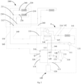
- the air conditioner includes an outdoor unit 100 and an indoor unit 200, where the outdoor unit 100 includes a compression mechanism and an outdoor side heat exchanger 141, and the indoor unit 200 includes a first heat exchanger 220 and a first throttle regulator 240; the air conditioner further includes: a discharge pipe 111 connected to a discharge side of the compression mechanism, a low-pressure suction pipe 113 connected to a low-pressure suction side of the compression mechanism, a first piping 140 connecting the discharge pipe 111, the outdoor side heat exchanger 141, the first throttle regulator 240, and the first heat exchanger 220 in sequence, and a second piping 150 connecting the first heat exchanger 220 and the low-pressure suction pipe 113, thus forming a refrigerant circuit; the outdoor unit 100 further includes a first switching device 131, the first switching device 131 being capable of switching between a first switching state of the first switching device 131
- the air conditioner in the first switching state the air conditioner is in the heating state, i.e., the first heat exchanger 220 is in the heating operation.
- the air conditioner In the second switching state, the air conditioner is in the cooling state.
- the first switching device 131 may be a four-way valve.
- the air conditioner further includes an economizer 143, where the economizer 143 is provided on the first piping 140 between the outdoor side heat exchanger 141 and the first throttle device; a first refrigerant flow path 143a and a second refrigerant flow path 143b are provided in the economizer 143, the first refrigerant flow path 143a being connected to the first piping 140 through a refrigerant bridge 600; and one end of the second refrigerant flow path 143b communicates with the first piping 140 through a liquid pickup pipe 145 and the other end communicates with both a medium-pressure suction port of the compressor 110 and the suction pipe through a return pipe 146, so that refrigerant flow directions in the first refrigerant flow path 143a and the second refrigerant flow path 143b are opposite.
- the first switching device 131 in the heating mode, is in the first state, in which case the discharge pipe 111 communicates with the second piping 150, so that the high-temperature and high-pressure refrigerant passes through the discharge pipe 111 and the second piping 150 and then enters the first heat exchanger 220 for heating, and then flows into the refrigerant bridge 600 through the first piping 140, and after being subject to the action of the refrigerant bridge 600, flows into the first refrigerant flow path 143a of the economizer 143, and flows back to the first piping 140 after passing through the first refrigerant flow path 143a, and passes through the outdoor throttle valve and the outdoor side heat exchanger 141, and then flows back to the compressor 110 through the suction pipe from the low-pressure suction port.
- the second refrigerant flow path 143b of the economizer 143 after liquid pickup and passing through the plate heat exchanger to exchange heat with the first refrigerant flow path 143a, flows through the return pipe 146 back to the medium-pressure suction pipe of the compressor 110. At the same time, the communication between the return pipe 146 and the suction pipe is cut off, so as to replenish air to the compressor 110, thus improving the heating capacity of the compressor 110 in low-temperature environments.
- the first switching device 131 is in the second state, in which case the discharge pipe 111 communicates with the first piping 140, and the high-temperature and high-pressure refrigerant passes through the discharge pipe 111 and the first piping 140, enters the outdoor side heat exchanger 141, then passes through the outdoor side heat exchanger 141 and then the outdoor throttle valve, and then enters the first refrigerant flow path 143a of the economizer 143 through the refrigerant bridge 600, and the first refrigerant flow path 143a passes through the plate heat exchanger and then flows back to the first piping 140, and then along the first piping 140 and through the first indoor throttle device, enters the first heat exchanger 220 for cooling; the inflow end of the second refrigerant flow path communicates with the first piping 140, and the refrigerant passes through the plate heat exchanger to exchange heat with the refrigerant in the first refrigerant flow path 143a (to perform heat exchange through the plate heat exchanger), and then flows through the return
- the economizer 143 includes a plate heat exchanger or a double-pipe heat exchanger having a first end 510 and a second end 520 provided opposite each other, where the first refrigerant flow path 143a enters through the first end 510 and exits through the second end 520 and the second refrigerant flow path 143b enters through the second end 520 and exits through the first end 510; or the first refrigerant flow path 143a enters through the second end 520 and exits through the first end 510 and the second refrigerant flow path 143b enters through the first end 510 and exits through the second end 520.
- the refrigerant in the first refrigerant flow path 143a and the refrigerant in the second refrigerant flow path 143b exchange heat through the plate heat exchanger or the double-pipe heat exchanger. Since the first refrigerant flow path 143a and the second refrigerant flow path 143b flow in opposite directions, the temperature difference between refrigerants in the first refrigerant flow path 143a and the second refrigerant flow path 143b is kept maximum, thus ensuring the heat exchange effect.
- the refrigerant bridge 600 may be in various forms, as long as it enables, as the refrigerant passes through the first piping 140 (whether the refrigerant flows from the indoor heat exchanger to the outdoor side heat exchanger 141, or from the outdoor side heat exchanger 141 to the indoor heat exchanger), the refrigerant flow direction in the first refrigerant flow path 143a to be always opposite to the refrigerant flow direction in the second refrigerant flow path 143b so as to increase the temperature difference and thus ensure the heat exchange effect.
- the refrigerant flow directions in the first refrigerant flow path 143a and the second refrigerant flow path 143b are always opposite (whether in the heating mode where the refrigerant flows from the indoor heat exchanger to the outdoor side heat exchanger 141, or in the cooling mode where the refrigerant flows from the outdoor side heat exchanger 141 to the indoor heat exchanger).
- the temperature difference between refrigerants in the first refrigerant flow path 143a and the second refrigerant flow path 143b is adequately maintained, so that the heat exchange effect between the first refrigerant flow path 143a and the second refrigerant flow path 143b can be ensured, which is conducive to ensuring the air replenishment effect of the economizer 143 on the compressor 110 in the heating mode, thus ensuring the heating capacity of the air conditioner in low-temperature environments; and which, at the same time, is conducive to ensuring the liquefaction effect (exhaust effect) of the economizer 143 on the refrigerant in the cooling mode, ensuring that the refrigerant entering the indoor throttle device is in the liquid state, thus eliminating the abnormal sound generated in the indoor throttling process.
- the conception of the present invention can be used not only for conventional air conditioners, but also for situations where multiple indoor heat exchangers are provided in the same one indoor unit 200, and also for situations where the refrigerant system has multiple indoor units 200.
- the increase in the complexity of the structure of a single indoor unit 200 itself, or the increase in the number of indoor units 200, will increase the length of the refrigerant pipeline.
- the effect of the present invention is to eliminate abnormal sound.
- the indoor unit 200 further includes a second heat exchanger 210, a second throttle regulator 230, and a thermal circulation device for delivering heat or cold from the indoor unit 200 into the room.
- the air conditioner further includes a third piping 160 and a branch pipe 112 branching off from the discharge pipe 111, the third piping 160 connecting a first intersection point 211 of the first piping 140, the second throttle regulator 230, the second heat exchanger 210, and the branch pipe 112 in sequence so as to form a refrigerant circuit, where the first intersection point 211 is located between the first throttle regulator 240 and the outdoor side heat exchanger 141; and the economizer 143 is located on the first piping 140 between the first intersection point 211 and the outdoor side heat exchanger 141.
- the thermal circulation device may be a wind wheel, and the rotation of the wind wheel delivers to the room the air for which heat has been exchanged with an initial heat exchanger and the second heat exchanger 210.
- the thermal circulation device may also be a water circulation device, where the first heat exchanger 220 and the second heat exchanger 210 deliver heat or cold to the room through the circulating water flowing in the water circulation device.
- the air conditioner can realize cooling by the first heat exchanger 220 and heating by the second heat exchanger 210, so that thermostatic dehumidification can be realized.
- the first throttle regulator 240 includes a solenoid throttle valve, such as a solenoid expansion valve
- the second throttle regulator 230 includes a solenoid throttle valve, such as a solenoid expansion valve.
- the first switching device 131 is in the second state, where the first heat exchanger 220 performs cooling at which point the refrigerant is discharged from the discharge pipe 111 and enters the second heat exchanger 210 through the branch pipe 112 and the third piping 160; and the second heat exchanger 210 performs heating at which point the refrigerant flows out of the second heat exchanger 210 and then flows into the second piping 150 and, along the second piping 150, passes through the refrigerant bridge 600, the economizer 143, the outdoor side heat exchanger 141 and the suction pipe and flows back to the low-pressure suction port of the compressor 110.
- the air conditioner further includes a second switching device 132, the second switching device 132 being capable of switching between a third switching state and a fourth switching state of the second switching device 132, where in the third switching state, the second switching device 132 causes the third piping 160 to communicate with the branch pipe 112, and in the fourth switching state, the second switching device 132 causes the third piping 160 to communicate with the suction pipe.
- the air conditioner is in a thermostatic dehumidification state.
- the air conditioner is in the cooling state, i.e., the first heat exchanger 220 and the second heat exchanger 210 perform cooling at the same time.
- the second switching device 132 may be a four-way valve.
- an auxiliary branch pipe which communicates with the suction pipe when the third piping 160 communicates with the branch pipe 112.
- the auxiliary branch pipe communicates with the low-pressure suction pipe 113 and the branch pipe 112.
- a filter and a capillary are provided on the auxiliary branch pipe.
- the first switching device 131 and the second switching device 132 may exist at the same time, so that the air conditioner can be switched among three states of thermostatic dehumidification, heating only and cooling only.
- the air conditioner further includes an outdoor side throttle regulator 142, the outdoor side throttle regulator 142 being located on the first piping 140 between the economizer 143 and the outdoor side heat exchanger 141.
- the outdoor side throttle regulator 142 includes an outdoor throttle valve, such as an electronic expansion valve.
- the specific operation of the economizer 143 will be described below based on the situation where there exist a first indoor heat exchanger and a second indoor heat exchanger in the room.
- the air conditioner further includes the economizer 143; the economizer 143 is provided on the first piping 140 between the outdoor side heat exchanger 141 and the first intersection point 211, and the return pipe 146 of the economizer 143 communicates with the medium-pressure suction port of the compressor 110.
- the return pipe 146 may be in various forms, and the return pipe 146 may include only the return pipe 146 body, or may include the return pipe 146 body and the first communication pipe 148, one end of the first communication pipe 148 communicating with the return pipe 146 body and the other end communicating with the medium-pressure suction port of the compressor 110.
- a first control valve 133 is provided on the return pipe 146 or on the first communication pipe 148 between the return pipe 146 and the medium-pressure suction port of the compressor 110.
- the compressor 110 at this point is an enhanced vapor injection compressor 110 having a low-pressure suction port and a medium-pressure suction port.
- the liquid pickup pipe 145 is provided with a liquid pickup throttle valve 144.
- the discharge from the compressor 110 after being switched by the first switching device 131 and the second switching device 132, enters the second heat exchanger 210 (the refrigerant enters through the third piping 160) and the first heat exchanger 220 (the refrigerant enters through the first piping 140), respectively, for heating, and the liquid refrigerant coming from the second heat exchanger 210 and the first heat exchanger 220 is divided into two parts when it passes through the economizer 143: the first part (through the refrigerant bridge 600 and the first refrigerant flow path 143a) is directly subjected to throttling and pressure reduction by the outdoor side throttle regulator 142 (electronic expansion valve) and then enters the outdoor side heat exchanger 141 for evaporation and heat absorption; and the second part (through the second refrigerant flow path 143b) is subjected to throttling and pressure reduction by the liquid pickup throttle valve 144 (electronic expansion valve), and then enters the economizer 143
- the system design of the enhanced vapor injection compressor 110 and the economizer 143 increases the refrigerant suction amount of the compressor 110 in low-temperature environments, which in turn increases the heat production at a low temperature, while reducing the compression ratio in low-temperature environments, so the reliability of the system can be improved.
- the inflow end of the liquid pickup pipe 145 communicates with the first piping 140 between the economizer 143 and the outdoor side heat exchanger 141, while in some other embodiments, the inflow end of the liquid pickup pipe 145 may also communicate with the first piping 140 between the economizer 143 and the first intersection point 211 (in the absence of the first intersection point 211, the inflow end of the liquid pickup pipe 145 communicates with the first piping 140 between the economizer 143 and the first indoor throttle regulator). That is, the refrigerant flows in through the refrigerant outflow end of the economizer 143, which is conducive to improving the reliability of liquid pickup.
- the junction between the inflow end of the liquid pickup pipe 145 and the first piping 140 is referred to as the liquid pickup point.
- the connection position is referred to as a first liquid pickup point 134, or referred to as an upstream liquid pickup point; and when the inflow end of the liquid pickup pipe 145 communicates with the first piping 140 between the economizer 143 and the first intersection point 211 (or the first indoor throttle regulator), the connection position is referred to as a second liquid pickup point 135, or referred to as a downstream liquid pickup point.
- the first liquid pickup point 134 or the upstream liquid pickup point is selected in order to replenish air to the compressor 110, thus increasing its heating capacity in low-temperature environments; and in the situation of cooling or thermostatic dehumidification (or dehumidification and reheating) by the indoor heat exchanger, the second liquid pickup point 135 or the downstream liquid pickup point is selected to cause the refrigerant entering the indoor unit 200 to be liquid as much as possible, thus avoiding the generation of abnormal sound during indoor throttling.
- the position of the liquid pickup port 840 By setting the position of the liquid pickup port 840 to be lower than that of the first piping 140, because the liquid refrigerant flows along the lower side pipe wall of the first piping 140 (the density of the refrigerant in the liquid state is greater than that in the gaseous state), so that when the refrigerant passes through the liquid pickup port 840, the liquid refrigerant enters preferentially under the action of gravity, thus ensuring that refrigerant picked up at the liquid pickup port 840 is in the liquid state.
- the liquid pickup port 840 may be formed in many ways, such as, for example, providing a liquid pickup structure 800 at the junction of the liquid pickup pipe 145 with the first piping 140, where the liquid pickup structure 800 has a liquid pickup chamber 810 and three refrigerant ports that communicate with the liquid pickup chamber 810, namely, a first refrigerant port 830, a second refrigerant port 820 and a liquid pickup port 840, the liquid pickup port 840 being located below the first refrigerant port 830 and the second refrigerant port 820. Both the first refrigerant port 830 and the second refrigerant port 820 communicate with the first piping 140, and the liquid pickup port 840 communicates with the inflow end of the liquid pickup pipe 145.
- the first refrigerant port 830 communicates with the first piping 140 near the outdoor heat exchanger
- the second refrigerant port 820 communicates with the first piping 140 near the first indoor throttle regulator.
- the liquid pickup port 840 is located at the bottom of the liquid pickup structure 800.
- the liquid pickup structure 800 may be in various shapes, such as rectangular, square, column, etc.
- the first refrigerant port 830 and the second refrigerant port 820 may be located at the two ends or at the top of the liquid pickup structure 800, but, of course, in some embodiments, the first piping 140 may also extend into the liquid pickup chamber 810 through the first refrigerant port 830 and the second refrigerant port 820.
- the air conditioner further includes a gas-liquid separator 120 and the economizer 143, the gas-liquid separator 120 being provided on the low-pressure suction pipe 113; and the economizer 143 is provided on the first piping 140 between the outdoor side heat exchanger 141 and the first intersection point 211, and the return pipe 146 of the economizer 143 communicates with the gas-liquid separator 120.
- the return pipe 146 includes the return pipe 146 body and the second communication pipe 147, one end of the second communication pipe 147 communicating with the return pipe 146 body and the other end communicating with the gas-liquid separator 120.
- the return pipe 146 communicates with the gas-liquid separator 120 through the low-pressure suction pipe 113, and a second control valve 149 is provided on the return pipe 146 or the second connection pipe 250 between the return pipe 146 and the low-pressure suction pipe 113.
- the refrigerant condensing temperature at the outlet of the outdoor side heat exchanger 141 is further reduced, which improves the subcooling degree and causes the refrigerant to condense completely to the liquid state, and the liquid refrigerant enters the indoor heat exchanger for heat absorption and evaporation after the throttling and pressure reduction by the indoor electronic expansion valves, so that the refrigerant passing through the indoor throttle devices is in the full liquid state, thus solving the problem of abnormal sound of refrigerant generated by the gas-liquid two-phase state refrigerant.
- the high-pressure and high-temperature gaseous refrigerant enters the outdoor side heat exchanger 141 for condensation and heat exchange
- the medium-temperature and high-pressure refrigerant in the gas-liquid two-phase state coming out of the outdoor side heat exchanger 141 enters the economizer 143 and is then divided into two parts: the first part, after the throttling and pressure reduction by the liquid pickup throttle valve 144, passes through the liquid pickup pipe 145 and then enters the economizer 143 for heat absorption and evaporation
- the evaporated gaseous refrigerant enters the gas-liquid separator 120 through the return pipe 146, the second control valve 149 (solenoid valve) and the connection pipe, and after being mixed with the gaseous refrigerant that has been subjected to heat absorption and evaporation by the indoor heat exchanger, enters the suction port of the compressor 110 together; and the second part, after further condensation and heat exchange by the
- the refrigerant condensing temperature at the outlet of the outdoor side heat exchanger 141 is further reduced, which improves the subcooling degree and causes the refrigerant to condense completely to the liquid state from the gas-liquid two-phase state, and the liquid refrigerant enters the indoor heat exchanger for heat absorption and evaporation after the throttling and pressure reduction by the indoor electronic expansion valves (the first throttle regulator 240 and the second throttle regulator 230), so that the refrigerant passing through the indoor throttle devices (the first throttle regulator 240 and the second throttle regulator 230) is in the full liquid state, thus solving the problem of abnormal sound of refrigerant generated by the gas-liquid two-phase refrigerant when passing through the throttle regulators, thereby improving the satisfaction of users
- the return pipe 146 communicates with the medium-pressure suction port of the compressor 110 and the gas-liquid separator 120, respectively, through different communication pipes, in which case the two communication pipes (the first communication pipe 148 and the second communication pipe 147) are provided with the first control valve 133 (near the compressor 110) and the second control valve 149 (near the gas-liquid separator 120), respectively.
- the return pipe 146 according to the invention includes the return pipe 146 body and the two communication pipes. In the heating mode, the second control valve 149 is closed and the first control valve 133 is opened, allowing the refrigerant to flow into the compressor 110 to improve heating capacity.
- the first control valve 133 In the cooling mode or thermostatic dehumidification mode, the first control valve 133 is closed and the second control valve 149 is opened to eliminate the abnormal sound.
- the second control valve 149 may also be closed and the first control valve 133 opened due to special working conditions.
- the air conditioner can adjust the first control valve 133 and the second control valve 149 according to the specific situation, thus improving the heating capacity of the air conditioner in the heating mode and reducing noise in the cooling and thermostatic dehumidification modes.
- the compressor 110 is an enhanced vapor injection compressor 110, and this compressor 110 has a medium-pressure suction port M (i.e., vapor injection port) in addition to the conventional high-pressure exhaust port P and low-pressure suction port S, where the medium-pressure refrigerant vapor enters the compressor 110 through this vapor injection port to increase the effective flow of refrigerant.
- M medium-pressure suction port
- the a port of the economizer 143 is connected to a third port 630 of the refrigerant bridge 600, the b port of the economizer 143 is connected to a fourth port 640 of the refrigerant bridge 600, the c port of the economizer 143 is connected to the liquid pickup pipe 145, the d port of the economizer 143 is connected to the return pipe 146, the liquid pickup throttle valve 144 is connected in series to the liquid pickup pipe 145, the first control valve 133 is connected in series to a communication pipe, and the second control valve 149 is connected in series to another communication pipe, with one end of the communication pipe being connected to the medium-pressure suction port M of the compressor 110, and the other communication pipe being connected to the inlet end of the gas-liquid separator 120.
- the air conditioner further includes multiple indoor units 200, and the form of heat exchangers included in each indoor unit 200 may be different, for example, one or more of an indoor machine with thermostatic dehumidification function (having both the first heat exchanger 220 and the second heat exchanger 210), an ordinary cooling/heating indoor machine (having only one heat exchanger and a corresponding throttle device), and an indoor machine with a conversion device that can freely switch between cooling or heating states may be included, so that the air conditioner can perform mixed operations of thermostatic dehumidification, cooling and heating at the same time.
- an indoor machine with thermostatic dehumidification function having both the first heat exchanger 220 and the second heat exchanger 210
- an ordinary cooling/heating indoor machine having only one heat exchanger and a corresponding throttle device
- an indoor machine with a conversion device that can freely switch between cooling or heating states
- the air conditioner further includes: a first connection pipe 260 branching off from a second intersection point 212 of the first piping 140 and a second connection pipe 250 branching off from the second piping 150, the second intersection point 212 being located between the first throttle regulator 240 and the outdoor side heat exchanger 141, and the air conditioner further includes multiple indoor units 200, the multiple indoor units 200 being connected in parallel to the first connection pipe 260 and the second connection pipe 250.
- the second switching device 132 is controlled using two solenoid valves.
- the third piping 160 communicates with the branch pipe 112 and communicates with the low-pressure suction pipe 113 or the second piping 150, with a third control valve 310 being provided on the branch pipe 112, and the third piping 160 communicates with the low-pressure suction pipe 113 or with the second piping 150 through the coupling pipe 114, with a fourth control valve 320 being provided on the coupling pipe 114.
- the end of the coupling pipe 114 away from the third piping 160 may communicate with either the second piping 150 between the first switching device 131 and the indoor heat exchanger or the second piping 150 between the first switching device 131 and the gas-liquid separator 120.
- the third control valve 310 and the fourth control valve 320 are separate control valves, the structure is simpler and more stable and reliable compared to the four-way valve.
- the third control valve 310 and the fourth control valve 320 may be solenoid valves. The solenoid valve can still work stably and reliably when liquid refrigerant enters, while in the four-way valve, if liquid refrigerant enters, its working stability will be affected. Therefore, the use of separate third control valve 310 and fourth control valve 320 can improve the stability and reliability of the operation and state switching of the air conditioner.
- the states of the third control valve 310 and the fourth control valve 320 in the case of power off may be set according to the actual requirements of the working conditions.
- the third control valve 310 as an example.
- the third control valve 310 may be selected as a normally open valve, that is, most of its work can be completed in the power-off state, and it needs to be powered on only when the state of the third control valve 310 needs to be switched.
- the third control valve 310 maintains a normally closed state for a long time, it is selected to be a normally closed valve. In this way, it is conducive to reducing the electrical energy consumed by the second switching device 132 (including the third control valve 310) during the operation of the air conditioner, thus contributing to the rational use of energy.
- the third piping 160, the branch pipe 112 and the coupling pipe 114 are connected at the first junction Q.
- the low-pressure suction pipe 113 may communicate with the other two pipes through the coupling pipe 114.
- one three-way valve may be provided at the first junction Q instead of two two-way valves.
- the three-way valve realizes the communication of the third piping 160 to the coupling pipe 114 and the branch pipe 112, respectively, and may control the opening and closing of the coupling pipe 114 and the branch pipe 112, respectively. In this way, it is conducive to improving the convenience of the connection of the third piping 160, the coupling pipe 114 and the branch pipe 112.
- the high-temperature and high-pressure refrigerant is discharged from an exhaust pipe and passes through the first switching device 131, the first piping 140, the outdoor side heat exchanger 141, and the economizer 143 in sequence, and then enters an evaporation heat exchanger and the first heat exchanger 220, respectively, for cooling.
- the third control valve 310 is closed and the fourth control valve 320 is opened.
- the high-temperature and high-pressure refrigerant is discharged from the exhaust pipe, and one part thereof passes through the first switching device 131 (which may be absent in some embodiments) and the second piping 150 in sequence, then enters the first heat exchanger 220 for heating, and then flows out of the first heat exchanger 220 and enters the first piping 140; and the other part passes through the branch pipe 112 and the third piping 160 in sequence and enters the second heat exchanger 210 for heating, and flows out of the second heat exchanger 210 and then enters the first piping 140, passes through the economizer 143, the outdoor side heat exchanger 141, and the first switching device 131, and then flows into the gas-liquid separator 120.
- the third control valve 310 is opened and the fourth control valve 320 is closed.
- Thermostatic dehumidification mode is the same as Thermostatic dehumidification mode:
- the high-temperature and high-pressure refrigerant is discharged from the exhaust pipe, and one part thereof passes through the first switching device 131 (which may be absent in some embodiments), the first piping 140, the outdoor side heat exchanger 141, and the economizer 143 in sequence, and then enters the first heat exchanger 220 for cooling, and then passes through the second piping 150 and the first switching device 131 and flows into the gas-liquid separator 120.
- the other part passes through the branch pipe 112 and the third piping 160 in sequence and enters the second heat exchanger 210 for heating, and then flows into the first heat exchanger 220 for cooling.
- the third control valve 310 is opened and the fourth control valve 320 is closed.
- the refrigerant bridge 600 has a first port 610, a second port 620, and a refrigerant passage that causes the first port 610 to communicate with the second port 620, and the refrigerant bridge 600 is connected to the first piping 140 through the first port 610 and the second port 620.
- the first port 610 communicates with the first piping 140 near the outdoor side heat exchanger 141
- the second port 620 communicates with the first piping 140 near the indoor unit 200.
- the refrigerant bridge 600 further has a second port 620 and a fourth port 640, where the refrigerant bridge 600 is connected to the first refrigerant flow path of the economizer 143 through the second port 620 and the fourth port 640.
- the refrigerant may enter the refrigerant bridge 600 through the first port 610 or the second port 620, flow into the first refrigerant flow path 143a through the third port 630 (the fourth port 640), pass through the first refrigerant flow path 143a and then enter the refrigerant bridge 600 through the fourth port 640 (the third port 630), and then flow into the first piping 140 through the second port 620 or the first port 610.
- the refrigerant bridge 600 has a third port 630 and a fourth port 640, with the two ends of the first refrigerant flow path 143a being connected to the third port 630 and the fourth port 640, respectively;
- the first port 610 communicates with the third port 630 through a first bridge section 650, the first bridge section 650 allowing unidirectional fluid flow from the first port 610 to the third port 630;
- the third port 630 communicates with the second port 620 through a second bridge section 660, the second bridge section 660 allowing unidirectional fluid flow from the second port 620 to the third port 630;
- the second port 620 communicates with the fourth port 640 through a third bridge section 670, the third bridge section 670 allowing unidirectional fluid flow from the fourth port 640 to the second port 620;
- the fourth port 640 communicates with the first port 610 through a fourth bridge section 680, the fourth bridge section
- liquid pickup is conducted at the first liquid pickup point 134 (the upstream liquid pickup point):
- the refrigerant after flowing out of the indoor heat exchanger, enters the first piping 140, and enters the first bridge section 650 along the first piping 140 through the first port 610, flows out through the third port 630 and then enters the first refrigerant flow path 143a of the economizer 143, enters through the first end 510 (in some embodiments, it may also enter through the second end 520 and flow out through the first end 510) into the plate heat exchanger or double-pipe heat exchanger for heat exchange and then flows out through the second end 520, and then enters the third bridge section 670 through the fourth port 640, flows out of the refrigerant bridge 600 through the second port 620 and enters the first piping 140, and then passes through the outdoor side throttle regulator 142 and the outdoor side heat exchanger 141 in sequence.
- the refrigerant after being subjected to liquid pickup at the first liquid pickup point 134 by the liquid pickup pipe 145, passes through the liquid pickup throttle valve 144 and enters through the second end 520 into the plate heat exchanger or double-pipe heat exchanger for heat exchange, and then flows out through the first end 510 (in some embodiments it may also enter through the first end 510 and flow out through the second end 520, as long as it is opposite to the first refrigerant flow path 143a), and then enters the return pipe 146 and, along the return pipe 146, flows back to the medium-pressure suction port of the compressor 110.
- liquid pickup is conducted at the second liquid pickup point 135 (the downstream liquid pickup point):
- the refrigerant after flowing out of the outdoor side heat exchanger 141, enters the first piping 140, and enters the second bridge section 660 along the first piping 140 through the second port 620, flows out through the third port 630 and then enters the first refrigerant flow path 143a of the economizer 143, enters through the first end 510 (in some embodiments, it may also enter through the second end 520 and flow out through the first end 510) into the plate heat exchanger or double-pipe heat exchanger for heat exchange and then flows out through the second end 520, and then enters the fourth bridge section 680 through the fourth port 640, flows out of the refrigerant bridge 600 through the first port 610 and enters the first piping 140, and then enters the indoor heat exchanger.
- the refrigerant after being subjected to liquid pickup at the second liquid pickup point 135 by the liquid pickup pipe 145, passes through the liquid pickup throttle valve 144 and enters through the second end 520 into the plate heat exchanger or double-pipe heat exchanger for heat exchange, and then flows out through the first end 510 (in some embodiments it may also enter through the first end 510 and flow out through the second end 520, as long as it is opposite to the first refrigerant flow path 143a), and then enters the return pipe 146, and along the return pipe 146 it flows back to the medium-pressure suction port of the compressor 110.
- the refrigerant bridge 600 has a third port 630 and a fourth port 640, with the two ends of the first refrigerant flow path 143a being connected to the third port 630 and the fourth port 640, respectively;
- the first port 610 communicates with the third port 630 through a first bridge section 650, the first bridge section 650 allowing unidirectional fluid flow from the third port 630 to the first port 610;
- the third port 630 communicates with the second port 620 through a second bridge section 660, the second bridge section 660 allowing unidirectional fluid flow from the third port 630 to the second port 620;
- the second port 620 communicates with the fourth port 640 through a third bridge section 670, the third bridge section 670 allowing unidirectional fluid flow from the second port 620 to the fourth port 640;
- the fourth port 640 communicates with the first port 610 through a fourth bridge section 680, the fourth bridge section 680 allowing unidirectional fluid flow from the first port 610 to the fourth port 640
- liquid pickup is conducted at the first liquid pickup point 134 (the upstream liquid pickup point):
- the refrigerant after flowing out of the indoor heat exchanger, enters the first piping 140, and enters the fourth bridge section 680 along the first piping 140 through the first port 610, flows out through the fourth port 640 and then enters the first refrigerant flow path 143a of the economizer 143, enters through the second end 520 (in some embodiments, it may also enter through the first end 510 and flow out through the second end 520) into the plate heat exchanger or double-pipe heat exchanger for heat exchange and then flows out through the first end 510, and then enters the second bridge section 660 through the third port 630, flows out of the refrigerant bridge 600 through the second port 620 and enters the first piping 140, and then passes through the outdoor side throttle regulator 142 and the outdoor side heat exchanger 141 in sequence.
- the refrigerant after being subjected to liquid pickup at the first liquid pickup point 134 by the liquid pickup pipe 145, passes through the liquid pickup throttle valve 144 and enters through the first end 510 into the plate heat exchanger or double-pipe heat exchanger for heat exchange, and then flows out through the second end 520 (in some embodiments it may also enter through the second end 520 and flow out through the first end 510, as long as it is opposite to the refrigerant flow direction in the first refrigerant flow path 143a), and then enters the return pipe 146 and, along the return pipe 146, flows back to the medium-pressure suction port of the compressor 110.
- liquid pickup is conducted at the second liquid pickup point 135 (the downstream liquid pickup point).
- the refrigerant after flowing out of the outdoor side heat exchanger 141, enters the first piping 140, and enters the third bridge section 670 along the first piping 140 through the second port 620, flows out through the fourth port 640 and then enters the first refrigerant flow path 143a of the economizer 143, enters through the second end 520 (in some embodiments, it may also enter through the first end 510 and flow out through the second end 520) into the plate heat exchanger or double-pipe heat exchanger for heat exchange and then flows out through the first end 510, and then enters the first bridge section 650 through the third port 630, flows out of the refrigerant bridge 600 through the first port 610 and enters the first piping 140, and then enters the indoor heat exchanger.
- the refrigerant after being subjected to liquid pickup at the second liquid pickup point 135 by the liquid pickup pipe 145, passes through the liquid pickup throttle valve 144 and enters through the first end 510 into the plate heat exchanger or double-pipe heat exchanger for heat exchange, and then flows out through the second end 520 (in some embodiments it may also enter through the second end 520 and flow out through the first end 510, as long as it is opposite to the first refrigerant flow direction), and then enters the return pipe 146 and, along the return pipe 146, flows back to the medium-pressure suction port of the compressor 110.
- the first bridge section 650, the second bridge section 660, the third bridge section 670, and the fourth bridge section 680 are each provided with a one-way valve 690 to achieve unidirectional fluid flow with each bridge section.
Landscapes
- Engineering & Computer Science (AREA)
- Mechanical Engineering (AREA)
- General Engineering & Computer Science (AREA)
- Physics & Mathematics (AREA)
- Thermal Sciences (AREA)
- Chemical & Material Sciences (AREA)
- Combustion & Propulsion (AREA)
- Compression-Type Refrigeration Machines With Reversible Cycles (AREA)
- Air Conditioning Control Device (AREA)
Claims (14)
- Climatiseur comprenant : une unité extérieure (100) comprenant un mécanisme amélioré de compression de vapeur et un échangeur de chaleur extérieur ; une unité intérieure (200) comprenant un premier échangeur de chaleur (220) et un premier régulateur d'étranglement (240) ; un tuyau d'évacuation (111) raccordé à un côté évacuation du mécanisme de compression, un tuyau d'aspiration à basse pression (113) raccordé à un côté aspiration à basse pression du mécanisme de compression, une première tuyauterie (140) raccordant successivement le tuyau d'évacuation (111), l'échangeur de chaleur extérieur, le premier régulateur d'étranglement (240) et le premier échangeur de chaleur (220), et une deuxième tuyauterie (150) raccordant le premier échangeur de chaleur (220) et le tuyau d'aspiration à basse pression (113), formant ainsi un circuit de fluide frigorigène ; un premier dispositif de commutation (131) capable de commuter entre : un premier état de commutation du premier dispositif de commutation (131), dans lequel le premier dispositif de commutation (131) fait communiquer la première tuyauterie (140) avec le tuyau d'aspiration et fait communiquer la deuxième tuyauterie (150) avec le tuyau d'évacuation (111) ; et un deuxième état de commutation du premier dispositif de commutation (131), dans lequel le premier dispositif de commutation (131) fait communiquer la première tuyauterie (140) avec le tuyau d'évacuation (111) et fait communiquer la deuxième tuyauterie (150) avec le tuyau d'aspiration ; et un économiseur (143) agencé sur la première tuyauterie (140) entre l'échangeur de chaleur extérieur et le premier dispositif d'étranglement ; une première voie d'écoulement de fluide frigorigène (143a) agencée dans l'économiseur (143) et raccordée à la première tuyauterie (140) par l'intermédiaire d'un pont de fluide frigorigène (600) ; et une seconde voie d'écoulement de fluide frigorigène (143b) agencée dans l'économiseur (143), une extrémité de la seconde voie d'écoulement de fluide frigorigène (143b) communiquant avec la première tuyauterie (140) par l'intermédiaire d'un tuyau de prélèvement de liquide (145) et l'autre extrémité de la seconde voie d'écoulement de fluide frigorigène (143b) communiquant à la fois avec un orifice d'aspiration à moyenne pression du compresseur (110) et le tuyau d'aspiration par l'intermédiaire d'un tuyau de retour (146), les directions d'écoulement de fluide frigorigène dans la première voie d'écoulement de fluide frigorigène (143a) et la seconde voie d'écoulement de fluide frigorigène (143b) étant opposées ;
le climatiseur étant caractérisé en ce que le tuyau de retour (146) comprend un corps de tuyau de retour, un premier tuyau de communication (148) et un second tuyau de communication (147) ; une extrémité du premier tuyau de communication (148) communique avec le corps de tuyau de retour et l'autre extrémité du premier tuyau de communication (148) communique avec l'orifice d'aspiration à moyenne pression du compresseur (110) ; le corps de tuyau de retour ou le premier tuyau de communication (148) est muni d'une première vanne de commande (133) ; et une extrémité du second tuyau de communication (147) communique avec le corps de tuyau de retour et l'autre extrémité du second tuyau de communication (147) communique avec le tuyau d'aspiration, et le second tuyau de communication (147) est muni d'une deuxième vanne de commande (149). - Climatiseur selon la revendication 1, dans lequel : le pont de fluide frigorigène (600) comporte un premier orifice (610), un deuxième orifice (620) et un passage de fluide frigorigène qui fait communiquer le premier orifice (610) avec le deuxième orifice (620) ; et le pont de fluide frigorigène (600) est raccordé à la première tuyauterie (140) par l'intermédiaire du premier orifice (610) et du deuxième orifice (620).
- Climatiseur selon la revendication 2, dans lequel : le pont de fluide frigorigène (600) comporte un troisième orifice (630) et un quatrième orifice (640) ; les deux extrémités de la première voie d'écoulement de fluide frigorigène (143a) sont raccordées respectivement au troisième orifice (630) et au quatrième orifice (640) ; le premier orifice (610) communique avec le troisième orifice (630) par l'intermédiaire d'une première section de pont (650) qui permet un écoulement de fluide unidirectionnel du premier orifice (610) vers le troisième orifice (630) ; le troisième orifice (630) communique avec le deuxième orifice (620) par l'intermédiaire d'une deuxième section de pont (660) qui permet un écoulement de fluide unidirectionnel du deuxième orifice (620) vers le troisième orifice (630) ; le deuxième orifice (620) communique avec le quatrième orifice (640) par l'intermédiaire d'une troisième section de pont (670) qui permet un écoulement de fluide unidirectionnel du quatrième orifice (640) vers le deuxième orifice (620) ; et le quatrième orifice (640) communique avec le premier orifice (610) par l'intermédiaire d'une quatrième section de pont (680) qui permet un écoulement de fluide unidirectionnel du quatrième orifice (640) vers le premier orifice (610).
- Climatiseur selon la revendication 2, dans lequel : le pont de fluide frigorigène (600) comporte un troisième orifice (630) et un quatrième orifice (640) ; les deux extrémités de la première voie d'écoulement de fluide frigorigène (143a) sont raccordées respectivement au troisième orifice (630) et au quatrième orifice (640) ; le premier orifice (610) communique avec le troisième orifice (630) par l'intermédiaire d'une première section de pont (650) qui permet un écoulement de fluide unidirectionnel du troisième orifice (630) vers le premier orifice (610) ; le troisième orifice (630) communique avec le deuxième orifice (620) par l'intermédiaire d'une deuxième section de pont (660) qui permet un écoulement de fluide unidirectionnel du troisième orifice (630) vers le deuxième orifice (620) ; le deuxième orifice (620) communique avec le quatrième orifice (640) par l'intermédiaire d'une troisième section de pont (670) qui permet un écoulement de fluide unidirectionnel du deuxième orifice (620) vers le quatrième orifice (640) ; et le quatrième orifice (640) communique avec le premier orifice (610) par l'intermédiaire d'une quatrième section de pont (680) qui permet un écoulement de fluide unidirectionnel du premier orifice (610) vers le quatrième orifice (640).
- Climatiseur selon la revendication 4, dans lequel la première section de pont (650), la deuxième section de pont (660), la troisième section de pont (670) et la quatrième section de pont (680) sont chacune munies d'une vanne unidirectionnelle (690).
- Climatiseur selon la revendication 1, dans lequel le tuyau de prélèvement de liquide (145) est muni d'une vanne d'étranglement de prélèvement de liquide (144).
- Climatiseur selon la revendication 1, dans lequel : une extrémité d'entrée du tuyau de prélèvement de liquide (145) communique avec la première tuyauterie (140) entre l'économiseur (143) et l'échangeur de chaleur côté extérieur ; ou une extrémité d'entrée du tuyau de prélèvement de liquide (145) communique avec la première tuyauterie (140) entre l'économiseur (143) et le premier régulateur d'étranglement intérieur.
- Climatiseur selon la revendication 1, dans lequel une extrémité d'entrée du tuyau de prélèvement de liquide (145) comporte un orifice de prélèvement de liquide (840) au niveau d'une jonction avec la première tuyauterie (140), l'orifice de prélèvement de liquide (840) étant situé en dessous de la première tuyauterie (140).
- Climatiseur selon la revendication 8, comprenant en outre : une structure de prélèvement de liquide (800) comprenant : une chambre de prélèvement de liquide (810) ; un premier orifice de fluide frigorigène (830) communiquant avec la chambre de prélèvement de liquide (810) ; un second orifice de fluide frigorigène (820) communiquant avec la chambre de prélèvement de liquide (810) ; et un orifice de prélèvement de liquide (840) communiquant avec la chambre de prélèvement de liquide (810), l'orifice de prélèvement de liquide (840) étant situé sous le premier orifice de fluide frigorigène (830) et le second orifice de fluide frigorigène (820).
- Climatiseur selon la revendication 1, comprenant en outre : un second échangeur de chaleur (210) ; un second régulateur d'étranglement (230) ; un tuyau de branchement (112) se branchant sur le tuyau d'évacuation (111) ; et une troisième tuyauterie (160) raccordant successivement un premier point d'intersection (211) de la première tuyauterie, le second régulateur d'étranglement (230), le second échangeur de chaleur (210) et le tuyau de branchement (112) ; le premier point d'intersection (211) étant situé entre le premier régulateur d'étranglement (240) et l'échangeur de chaleur extérieur, l'économiseur (143) étant situé sur la première tuyauterie (140) entre le premier point d'intersection (211) et l'échangeur de chaleur extérieur.
- Climatiseur selon la revendication 10, comprenant en outre : un tuyau d'accouplement (114) ; une troisième vanne de commande (310) agencée sur le tuyau de branchement (112) pour commander l'ouverture et la fermeture du tuyau de branchement (112) ; et une quatrième vanne de commande (320) agencée sur le tuyau d'accouplement (114) pour commander l'ouverture et la fermeture du tuyau d'accouplement (114) ; la troisième tuyauterie (160) communiquant avec le tuyau de branchement (112), la troisième tuyauterie (160) communiquant avec le tuyau d'aspiration à basse pression (113) ou avec la deuxième tuyauterie (150) par l'intermédiaire du tuyau d'accouplement (114), le climatiseur comprenant éventuellement en outre : un second dispositif de commutation (132) capable de commuter entre un troisième état de commutation du second dispositif de commutation (132), dans lequel le second dispositif de commutation (132) fait communiquer la troisième tuyauterie (160) avec le tuyau de branchement (112), et un quatrième état de commutation du second dispositif de commutation (132), dans lequel le second dispositif de commutation (132) fait communiquer la troisième tuyauterie (160) avec la tuyauterie d'aspiration.
- Climatiseur selon la revendication 1, comprenant en outre un régulateur d'étranglement côté extérieur (142), le régulateur d'étranglement côté extérieur (142) étant situé sur la première tuyauterie (140) entre l'économiseur (143) et l'échangeur de chaleur côté extérieur.
- Climatiseur selon la revendication 1, comprenant en outre : un premier tuyau de raccordement (260) se branchant sur un second point d'intersection (212) de la première tuyauterie (140), le second point d'intersection (212) étant situé entre le premier régulateur d'étranglement (240) et l'échangeur de chaleur extérieur ; un second tuyau de raccordement (250) se branchant sur la deuxième tuyauterie (150) ; et une pluralité d'unités intérieures (200) raccordées en parallèle au premier tuyau de raccordement (260) et au second tuyau de raccordement (250).
- Climatiseur selon l'une quelconque des revendications 1 à 13, dans lequel l'économiseur (143) comprend : un échangeur de chaleur à plaques ou un échangeur de chaleur à double tuyau, qui comporte une première extrémité (510) et une seconde extrémité (520) opposées l'une à l'autre, la première voie d'écoulement de fluide frigorigène (143a) entrant par la première extrémité (510) et sortant par la seconde extrémité (520) et la seconde voie d'écoulement de fluide frigorigène (143b) entrant par la seconde extrémité (520) et sortant par la première extrémité (510) ; ou la première voie d'écoulement de fluide frigorigène (143a) entrant par la seconde extrémité (520) et sortant par la première extrémité (510) et la seconde voie d'écoulement de fluide frigorigène (143b) entrant par la première extrémité (510) et sortant par la seconde extrémité (520).
Applications Claiming Priority (3)
| Application Number | Priority Date | Filing Date | Title |
|---|---|---|---|
| CN201921830849.6U CN211177490U (zh) | 2019-10-28 | 2019-10-28 | 空调器 |
| CN201911034323.1A CN112797658A (zh) | 2019-10-28 | 2019-10-28 | 空调器 |
| PCT/CN2020/079187 WO2021082331A1 (fr) | 2019-10-28 | 2020-03-13 | Climatiseur |
Publications (3)
| Publication Number | Publication Date |
|---|---|
| EP4008973A1 EP4008973A1 (fr) | 2022-06-08 |
| EP4008973A4 EP4008973A4 (fr) | 2022-09-14 |
| EP4008973B1 true EP4008973B1 (fr) | 2025-03-05 |
Family
ID=75714811
Family Applications (1)
| Application Number | Title | Priority Date | Filing Date |
|---|---|---|---|
| EP20882824.4A Active EP4008973B1 (fr) | 2019-10-28 | 2020-03-13 | Climatiseur |
Country Status (3)
| Country | Link |
|---|---|
| US (1) | US20220325924A1 (fr) |
| EP (1) | EP4008973B1 (fr) |
| WO (1) | WO2021082331A1 (fr) |
Family Cites Families (15)
| Publication number | Priority date | Publication date | Assignee | Title |
|---|---|---|---|---|
| US7131294B2 (en) * | 2004-01-13 | 2006-11-07 | Tecumseh Products Company | Method and apparatus for control of carbon dioxide gas cooler pressure by use of a capillary tube |
| EP1780479A4 (fr) * | 2004-07-01 | 2013-12-11 | Daikin Ind Ltd | Refroidisseur et climatiseur |
| JP2006300371A (ja) * | 2005-04-18 | 2006-11-02 | Daikin Ind Ltd | 空気調和機 |
| JP2009127902A (ja) * | 2007-11-21 | 2009-06-11 | Mitsubishi Electric Corp | 冷凍装置及び圧縮機 |
| JP4569708B2 (ja) * | 2008-12-05 | 2010-10-27 | ダイキン工業株式会社 | 冷凍装置 |
| KR101552618B1 (ko) * | 2009-02-25 | 2015-09-11 | 엘지전자 주식회사 | 공기 조화기 |
| CN201837139U (zh) * | 2009-06-01 | 2011-05-18 | 特灵空调系统(中国)有限公司 | 喷汽增焓热泵空调热水机组 |
| JP5516712B2 (ja) * | 2012-05-28 | 2014-06-11 | ダイキン工業株式会社 | 冷凍装置 |
| CN203083058U (zh) * | 2013-02-01 | 2013-07-24 | 珠海格力电器股份有限公司 | 空调器 |
| KR102163859B1 (ko) * | 2013-04-15 | 2020-10-12 | 엘지전자 주식회사 | 공기조화기 및 그 제어방법 |
| CN104613665A (zh) * | 2015-02-02 | 2015-05-13 | 珠海格力电器股份有限公司 | 热泵空调系统 |
| CN204494894U (zh) * | 2015-02-02 | 2015-07-22 | 珠海格力电器股份有限公司 | 热泵空调系统 |
| CN105004090A (zh) * | 2015-07-09 | 2015-10-28 | 广东美的暖通设备有限公司 | 一种多联机空调系统及该系统过冷和喷气增焓的方法 |
| CN205939467U (zh) * | 2016-08-19 | 2017-02-08 | 广东美的暖通设备有限公司 | 多联机空调系统 |
| CN107990585A (zh) * | 2017-12-26 | 2018-05-04 | 南京天加环境科技有限公司 | 一种改进的喷气增焓空调系统 |
-
2020
- 2020-03-13 WO PCT/CN2020/079187 patent/WO2021082331A1/fr not_active Ceased
- 2020-03-13 US US17/764,832 patent/US20220325924A1/en active Pending
- 2020-03-13 EP EP20882824.4A patent/EP4008973B1/fr active Active
Also Published As
| Publication number | Publication date |
|---|---|
| US20220325924A1 (en) | 2022-10-13 |
| EP4008973A1 (fr) | 2022-06-08 |
| EP4008973A4 (fr) | 2022-09-14 |
| WO2021082331A1 (fr) | 2021-05-06 |
Similar Documents
| Publication | Publication Date | Title |
|---|---|---|
| EP3734167B1 (fr) | Système de climatisation | |
| US11739991B2 (en) | Air conditioning system and control method for air conditioning system | |
| CN109386989B (zh) | 两管制喷气增焓室外机及多联机系统 | |
| CN112013471B (zh) | 空调器及其控制方法 | |
| CN112013515A (zh) | 空调器的控制方法 | |
| WO2020082740A1 (fr) | Unité externe d'augmentation d'enthalpie par jet à double commande et système de climatisation à divisions multiples | |
| CN209944565U (zh) | 空调器 | |
| CN213272814U (zh) | 多联式空调系统 | |
| CN207146975U (zh) | 热回收多联机空调系统 | |
| CN111649504B (zh) | 基于太阳能的制冷剂有源喷射热泵及其控制方法 | |
| CN210832605U (zh) | 空调器 | |
| CN215930175U (zh) | 一种制冷系统 | |
| CN107477900A (zh) | 空调循环系统和循环方法及空调 | |
| CN210832381U (zh) | 空调系统 | |
| CN112710101B (zh) | 空调器及其控制方法 | |
| CN112710100B (zh) | 空调器及其控制方法 | |
| CN109340919B (zh) | 空调器 | |
| EP3734199B1 (fr) | Système de climatisation | |
| CN220355711U (zh) | 换热系统和空调器 | |
| CN115682202B (zh) | 蓄能空调系统 | |
| CN113932482B (zh) | 可切换模式的节能型焓差实验室换热系统 | |
| CN211177490U (zh) | 空调器 | |
| CN215930176U (zh) | 一种制冷系统 | |
| EP4008973A1 (fr) | Climatiseur | |
| CN113465220B (zh) | 一种制冷系统及控制方法 |
Legal Events
| Date | Code | Title | Description |
|---|---|---|---|
| STAA | Information on the status of an ep patent application or granted ep patent |
Free format text: STATUS: THE INTERNATIONAL PUBLICATION HAS BEEN MADE |
|
| PUAI | Public reference made under article 153(3) epc to a published international application that has entered the european phase |
Free format text: ORIGINAL CODE: 0009012 |
|
| STAA | Information on the status of an ep patent application or granted ep patent |
Free format text: STATUS: REQUEST FOR EXAMINATION WAS MADE |
|
| 17P | Request for examination filed |
Effective date: 20220304 |
|
| AK | Designated contracting states |
Kind code of ref document: A1 Designated state(s): AL AT BE BG CH CY CZ DE DK EE ES FI FR GB GR HR HU IE IS IT LI LT LU LV MC MK MT NL NO PL PT RO RS SE SI SK SM TR |
|
| A4 | Supplementary search report drawn up and despatched |
Effective date: 20220818 |
|
| RIC1 | Information provided on ipc code assigned before grant |
Ipc: F25B 40/02 20060101ALI20220811BHEP Ipc: F24F 3/06 20060101AFI20220811BHEP |
|
| DAV | Request for validation of the european patent (deleted) | ||
| DAX | Request for extension of the european patent (deleted) | ||
| GRAP | Despatch of communication of intention to grant a patent |
Free format text: ORIGINAL CODE: EPIDOSNIGR1 |
|
| STAA | Information on the status of an ep patent application or granted ep patent |
Free format text: STATUS: GRANT OF PATENT IS INTENDED |
|
| INTG | Intention to grant announced |
Effective date: 20241112 |
|
| GRAS | Grant fee paid |
Free format text: ORIGINAL CODE: EPIDOSNIGR3 |
|
| GRAA | (expected) grant |
Free format text: ORIGINAL CODE: 0009210 |
|
| STAA | Information on the status of an ep patent application or granted ep patent |
Free format text: STATUS: THE PATENT HAS BEEN GRANTED |
|
| AK | Designated contracting states |
Kind code of ref document: B1 Designated state(s): AL AT BE BG CH CY CZ DE DK EE ES FI FR GB GR HR HU IE IS IT LI LT LU LV MC MK MT NL NO PL PT RO RS SE SI SK SM TR |
|
| REG | Reference to a national code |
Ref country code: GB Ref legal event code: FG4D |
|
| REG | Reference to a national code |
Ref country code: CH Ref legal event code: EP |
|
| REG | Reference to a national code |
Ref country code: DE Ref legal event code: R096 Ref document number: 602020047414 Country of ref document: DE |
|
| REG | Reference to a national code |
Ref country code: IE Ref legal event code: FG4D |
|
| PG25 | Lapsed in a contracting state [announced via postgrant information from national office to epo] |
Ref country code: RS Free format text: LAPSE BECAUSE OF FAILURE TO SUBMIT A TRANSLATION OF THE DESCRIPTION OR TO PAY THE FEE WITHIN THE PRESCRIBED TIME-LIMIT Effective date: 20250605 |
|
| PG25 | Lapsed in a contracting state [announced via postgrant information from national office to epo] |
Ref country code: FI Free format text: LAPSE BECAUSE OF FAILURE TO SUBMIT A TRANSLATION OF THE DESCRIPTION OR TO PAY THE FEE WITHIN THE PRESCRIBED TIME-LIMIT Effective date: 20250305 |
|
| REG | Reference to a national code |
Ref country code: NL Ref legal event code: MP Effective date: 20250305 |
|
| PG25 | Lapsed in a contracting state [announced via postgrant information from national office to epo] |
Ref country code: ES Free format text: LAPSE BECAUSE OF FAILURE TO SUBMIT A TRANSLATION OF THE DESCRIPTION OR TO PAY THE FEE WITHIN THE PRESCRIBED TIME-LIMIT Effective date: 20250305 |
|
| REG | Reference to a national code |
Ref country code: LT Ref legal event code: MG9D |
|
| PG25 | Lapsed in a contracting state [announced via postgrant information from national office to epo] |
Ref country code: NO Free format text: LAPSE BECAUSE OF FAILURE TO SUBMIT A TRANSLATION OF THE DESCRIPTION OR TO PAY THE FEE WITHIN THE PRESCRIBED TIME-LIMIT Effective date: 20250605 |
|
| PG25 | Lapsed in a contracting state [announced via postgrant information from national office to epo] |
Ref country code: HR Free format text: LAPSE BECAUSE OF FAILURE TO SUBMIT A TRANSLATION OF THE DESCRIPTION OR TO PAY THE FEE WITHIN THE PRESCRIBED TIME-LIMIT Effective date: 20250305 |
|
| PG25 | Lapsed in a contracting state [announced via postgrant information from national office to epo] |
Ref country code: LV Free format text: LAPSE BECAUSE OF FAILURE TO SUBMIT A TRANSLATION OF THE DESCRIPTION OR TO PAY THE FEE WITHIN THE PRESCRIBED TIME-LIMIT Effective date: 20250305 |
|
| PG25 | Lapsed in a contracting state [announced via postgrant information from national office to epo] |
Ref country code: BG Free format text: LAPSE BECAUSE OF FAILURE TO SUBMIT A TRANSLATION OF THE DESCRIPTION OR TO PAY THE FEE WITHIN THE PRESCRIBED TIME-LIMIT Effective date: 20250305 Ref country code: GR Free format text: LAPSE BECAUSE OF FAILURE TO SUBMIT A TRANSLATION OF THE DESCRIPTION OR TO PAY THE FEE WITHIN THE PRESCRIBED TIME-LIMIT Effective date: 20250606 |
|
| REG | Reference to a national code |
Ref country code: AT Ref legal event code: MK05 Ref document number: 1773223 Country of ref document: AT Kind code of ref document: T Effective date: 20250305 |
|
| PG25 | Lapsed in a contracting state [announced via postgrant information from national office to epo] |
Ref country code: NL Free format text: LAPSE BECAUSE OF FAILURE TO SUBMIT A TRANSLATION OF THE DESCRIPTION OR TO PAY THE FEE WITHIN THE PRESCRIBED TIME-LIMIT Effective date: 20250305 |
|
| PG25 | Lapsed in a contracting state [announced via postgrant information from national office to epo] |
Ref country code: SE Free format text: LAPSE BECAUSE OF FAILURE TO SUBMIT A TRANSLATION OF THE DESCRIPTION OR TO PAY THE FEE WITHIN THE PRESCRIBED TIME-LIMIT Effective date: 20250305 |
|
| PG25 | Lapsed in a contracting state [announced via postgrant information from national office to epo] |
Ref country code: SM Free format text: LAPSE BECAUSE OF FAILURE TO SUBMIT A TRANSLATION OF THE DESCRIPTION OR TO PAY THE FEE WITHIN THE PRESCRIBED TIME-LIMIT Effective date: 20250305 |
|
| PG25 | Lapsed in a contracting state [announced via postgrant information from national office to epo] |
Ref country code: PT Free format text: LAPSE BECAUSE OF FAILURE TO SUBMIT A TRANSLATION OF THE DESCRIPTION OR TO PAY THE FEE WITHIN THE PRESCRIBED TIME-LIMIT Effective date: 20250707 |
|
| PG25 | Lapsed in a contracting state [announced via postgrant information from national office to epo] |
Ref country code: PL Free format text: LAPSE BECAUSE OF FAILURE TO SUBMIT A TRANSLATION OF THE DESCRIPTION OR TO PAY THE FEE WITHIN THE PRESCRIBED TIME-LIMIT Effective date: 20250305 Ref country code: IT Free format text: LAPSE BECAUSE OF FAILURE TO SUBMIT A TRANSLATION OF THE DESCRIPTION OR TO PAY THE FEE WITHIN THE PRESCRIBED TIME-LIMIT Effective date: 20250305 |
|
| PG25 | Lapsed in a contracting state [announced via postgrant information from national office to epo] |
Ref country code: AT Free format text: LAPSE BECAUSE OF FAILURE TO SUBMIT A TRANSLATION OF THE DESCRIPTION OR TO PAY THE FEE WITHIN THE PRESCRIBED TIME-LIMIT Effective date: 20250305 |
|
| PG25 | Lapsed in a contracting state [announced via postgrant information from national office to epo] |
Ref country code: CZ Free format text: LAPSE BECAUSE OF FAILURE TO SUBMIT A TRANSLATION OF THE DESCRIPTION OR TO PAY THE FEE WITHIN THE PRESCRIBED TIME-LIMIT Effective date: 20250305 Ref country code: EE Free format text: LAPSE BECAUSE OF FAILURE TO SUBMIT A TRANSLATION OF THE DESCRIPTION OR TO PAY THE FEE WITHIN THE PRESCRIBED TIME-LIMIT Effective date: 20250305 |
|
| REG | Reference to a national code |
Ref country code: CH Ref legal event code: H13 Free format text: ST27 STATUS EVENT CODE: U-0-0-H10-H13 (AS PROVIDED BY THE NATIONAL OFFICE) Effective date: 20251023 |
|
| PG25 | Lapsed in a contracting state [announced via postgrant information from national office to epo] |
Ref country code: RO Free format text: LAPSE BECAUSE OF FAILURE TO SUBMIT A TRANSLATION OF THE DESCRIPTION OR TO PAY THE FEE WITHIN THE PRESCRIBED TIME-LIMIT Effective date: 20250305 |
|
| PG25 | Lapsed in a contracting state [announced via postgrant information from national office to epo] |
Ref country code: SK Free format text: LAPSE BECAUSE OF FAILURE TO SUBMIT A TRANSLATION OF THE DESCRIPTION OR TO PAY THE FEE WITHIN THE PRESCRIBED TIME-LIMIT Effective date: 20250305 |
|
| PG25 | Lapsed in a contracting state [announced via postgrant information from national office to epo] |
Ref country code: IS Free format text: LAPSE BECAUSE OF FAILURE TO SUBMIT A TRANSLATION OF THE DESCRIPTION OR TO PAY THE FEE WITHIN THE PRESCRIBED TIME-LIMIT Effective date: 20250705 |
|
| PG25 | Lapsed in a contracting state [announced via postgrant information from national office to epo] |
Ref country code: LU Free format text: LAPSE BECAUSE OF NON-PAYMENT OF DUE FEES Effective date: 20250313 |
|
| REG | Reference to a national code |
Ref country code: DE Ref legal event code: R097 Ref document number: 602020047414 Country of ref document: DE |
|
| REG | Reference to a national code |
Ref country code: BE Ref legal event code: MM Effective date: 20250331 |
|
| PG25 | Lapsed in a contracting state [announced via postgrant information from national office to epo] |
Ref country code: MC Free format text: LAPSE BECAUSE OF FAILURE TO SUBMIT A TRANSLATION OF THE DESCRIPTION OR TO PAY THE FEE WITHIN THE PRESCRIBED TIME-LIMIT Effective date: 20250305 |
|
| PLBE | No opposition filed within time limit |
Free format text: ORIGINAL CODE: 0009261 |
|
| STAA | Information on the status of an ep patent application or granted ep patent |
Free format text: STATUS: NO OPPOSITION FILED WITHIN TIME LIMIT |
|
| PG25 | Lapsed in a contracting state [announced via postgrant information from national office to epo] |
Ref country code: DK Free format text: LAPSE BECAUSE OF FAILURE TO SUBMIT A TRANSLATION OF THE DESCRIPTION OR TO PAY THE FEE WITHIN THE PRESCRIBED TIME-LIMIT Effective date: 20250305 |
|
| REG | Reference to a national code |
Ref country code: CH Ref legal event code: L10 Free format text: ST27 STATUS EVENT CODE: U-0-0-L10-L00 (AS PROVIDED BY THE NATIONAL OFFICE) Effective date: 20260114 |
|
| PG25 | Lapsed in a contracting state [announced via postgrant information from national office to epo] |
Ref country code: BE Free format text: LAPSE BECAUSE OF NON-PAYMENT OF DUE FEES Effective date: 20250331 |
|
| PG25 | Lapsed in a contracting state [announced via postgrant information from national office to epo] |
Ref country code: CH Free format text: LAPSE BECAUSE OF NON-PAYMENT OF DUE FEES Effective date: 20250331 |
|
| PG25 | Lapsed in a contracting state [announced via postgrant information from national office to epo] |
Ref country code: IE Free format text: LAPSE BECAUSE OF NON-PAYMENT OF DUE FEES Effective date: 20250313 |
|
| 26N | No opposition filed |
Effective date: 20251208 |
|
| GBPC | Gb: european patent ceased through non-payment of renewal fee |
Effective date: 20250605 |
|
| PG25 | Lapsed in a contracting state [announced via postgrant information from national office to epo] |
Ref country code: GB Free format text: LAPSE BECAUSE OF NON-PAYMENT OF DUE FEES Effective date: 20250605 |
|
| PGFP | Annual fee paid to national office [announced via postgrant information from national office to epo] |
Ref country code: DE Payment date: 20260324 Year of fee payment: 7 |
|
| PG25 | Lapsed in a contracting state [announced via postgrant information from national office to epo] |
Ref country code: FR Free format text: LAPSE BECAUSE OF NON-PAYMENT OF DUE FEES Effective date: 20250505 |