EP4008979B1 - Dispositif pour effectuer en toute sécurité un cycle thermodynamique du sens anti-horaire - Google Patents
Dispositif pour effectuer en toute sécurité un cycle thermodynamique du sens anti-horaire Download PDFInfo
- Publication number
- EP4008979B1 EP4008979B1 EP20211245.4A EP20211245A EP4008979B1 EP 4008979 B1 EP4008979 B1 EP 4008979B1 EP 20211245 A EP20211245 A EP 20211245A EP 4008979 B1 EP4008979 B1 EP 4008979B1
- Authority
- EP
- European Patent Office
- Prior art keywords
- adsorber
- inner housing
- working fluid
- gas
- heavy
- Prior art date
- Legal status (The legal status is an assumption and is not a legal conclusion. Google has not performed a legal analysis and makes no representation as to the accuracy of the status listed.)
- Active
Links
Images

Classifications
-
- F—MECHANICAL ENGINEERING; LIGHTING; HEATING; WEAPONS; BLASTING
- F25—REFRIGERATION OR COOLING; COMBINED HEATING AND REFRIGERATION SYSTEMS; HEAT PUMP SYSTEMS; MANUFACTURE OR STORAGE OF ICE; LIQUEFACTION SOLIDIFICATION OF GASES
- F25B—REFRIGERATION MACHINES, PLANTS OR SYSTEMS; COMBINED HEATING AND REFRIGERATION SYSTEMS; HEAT PUMP SYSTEMS
- F25B49/00—Arrangement or mounting of control or safety devices
- F25B49/005—Arrangement or mounting of control or safety devices of safety devices
-
- B—PERFORMING OPERATIONS; TRANSPORTING
- B01—PHYSICAL OR CHEMICAL PROCESSES OR APPARATUS IN GENERAL
- B01J—CHEMICAL OR PHYSICAL PROCESSES, e.g. CATALYSIS OR COLLOID CHEMISTRY; THEIR RELEVANT APPARATUS
- B01J20/00—Solid sorbent compositions or filter aid compositions; Sorbents for chromatography; Processes for preparing, regenerating or reactivating thereof
- B01J20/02—Solid sorbent compositions or filter aid compositions; Sorbents for chromatography; Processes for preparing, regenerating or reactivating thereof comprising inorganic material
- B01J20/20—Solid sorbent compositions or filter aid compositions; Sorbents for chromatography; Processes for preparing, regenerating or reactivating thereof comprising inorganic material comprising free carbon; comprising carbon obtained by carbonising processes
-
- B—PERFORMING OPERATIONS; TRANSPORTING
- B01—PHYSICAL OR CHEMICAL PROCESSES OR APPARATUS IN GENERAL
- B01J—CHEMICAL OR PHYSICAL PROCESSES, e.g. CATALYSIS OR COLLOID CHEMISTRY; THEIR RELEVANT APPARATUS
- B01J20/00—Solid sorbent compositions or filter aid compositions; Sorbents for chromatography; Processes for preparing, regenerating or reactivating thereof
- B01J20/28—Solid sorbent compositions or filter aid compositions; Sorbents for chromatography; Processes for preparing, regenerating or reactivating thereof characterised by their form or physical properties
- B01J20/28002—Solid sorbent compositions or filter aid compositions; Sorbents for chromatography; Processes for preparing, regenerating or reactivating thereof characterised by their form or physical properties characterised by their physical properties
- B01J20/28004—Sorbent size or size distribution, e.g. particle size
-
- B—PERFORMING OPERATIONS; TRANSPORTING
- B01—PHYSICAL OR CHEMICAL PROCESSES OR APPARATUS IN GENERAL
- B01J—CHEMICAL OR PHYSICAL PROCESSES, e.g. CATALYSIS OR COLLOID CHEMISTRY; THEIR RELEVANT APPARATUS
- B01J20/00—Solid sorbent compositions or filter aid compositions; Sorbents for chromatography; Processes for preparing, regenerating or reactivating thereof
- B01J20/28—Solid sorbent compositions or filter aid compositions; Sorbents for chromatography; Processes for preparing, regenerating or reactivating thereof characterised by their form or physical properties
- B01J20/28014—Solid sorbent compositions or filter aid compositions; Sorbents for chromatography; Processes for preparing, regenerating or reactivating thereof characterised by their form or physical properties characterised by their form
- B01J20/28016—Particle form
- B01J20/28019—Spherical, ellipsoidal or cylindrical
-
- F—MECHANICAL ENGINEERING; LIGHTING; HEATING; WEAPONS; BLASTING
- F25—REFRIGERATION OR COOLING; COMBINED HEATING AND REFRIGERATION SYSTEMS; HEAT PUMP SYSTEMS; MANUFACTURE OR STORAGE OF ICE; LIQUEFACTION SOLIDIFICATION OF GASES
- F25B—REFRIGERATION MACHINES, PLANTS OR SYSTEMS; COMBINED HEATING AND REFRIGERATION SYSTEMS; HEAT PUMP SYSTEMS
- F25B2339/00—Details of evaporators; Details of condensers
- F25B2339/04—Details of condensers
- F25B2339/047—Water-cooled condensers
-
- F—MECHANICAL ENGINEERING; LIGHTING; HEATING; WEAPONS; BLASTING
- F25—REFRIGERATION OR COOLING; COMBINED HEATING AND REFRIGERATION SYSTEMS; HEAT PUMP SYSTEMS; MANUFACTURE OR STORAGE OF ICE; LIQUEFACTION SOLIDIFICATION OF GASES
- F25B—REFRIGERATION MACHINES, PLANTS OR SYSTEMS; COMBINED HEATING AND REFRIGERATION SYSTEMS; HEAT PUMP SYSTEMS
- F25B2400/00—Component parts or details not otherwise provided for in this subclass
- F25B2400/12—Inflammable refrigerants
-
- F—MECHANICAL ENGINEERING; LIGHTING; HEATING; WEAPONS; BLASTING
- F25—REFRIGERATION OR COOLING; COMBINED HEATING AND REFRIGERATION SYSTEMS; HEAT PUMP SYSTEMS; MANUFACTURE OR STORAGE OF ICE; LIQUEFACTION SOLIDIFICATION OF GASES
- F25B—REFRIGERATION MACHINES, PLANTS OR SYSTEMS; COMBINED HEATING AND REFRIGERATION SYSTEMS; HEAT PUMP SYSTEMS
- F25B25/00—Machines, plants or systems, using a combination of modes of operation covered by two or more of the groups F25B1/00 - F25B23/00
- F25B25/005—Machines, plants or systems, using a combination of modes of operation covered by two or more of the groups F25B1/00 - F25B23/00 using primary and secondary systems
-
- F—MECHANICAL ENGINEERING; LIGHTING; HEATING; WEAPONS; BLASTING
- F25—REFRIGERATION OR COOLING; COMBINED HEATING AND REFRIGERATION SYSTEMS; HEAT PUMP SYSTEMS; MANUFACTURE OR STORAGE OF ICE; LIQUEFACTION SOLIDIFICATION OF GASES
- F25B—REFRIGERATION MACHINES, PLANTS OR SYSTEMS; COMBINED HEATING AND REFRIGERATION SYSTEMS; HEAT PUMP SYSTEMS
- F25B2500/00—Problems to be solved
- F25B2500/12—Sound
-
- F—MECHANICAL ENGINEERING; LIGHTING; HEATING; WEAPONS; BLASTING
- F25—REFRIGERATION OR COOLING; COMBINED HEATING AND REFRIGERATION SYSTEMS; HEAT PUMP SYSTEMS; MANUFACTURE OR STORAGE OF ICE; LIQUEFACTION SOLIDIFICATION OF GASES
- F25B—REFRIGERATION MACHINES, PLANTS OR SYSTEMS; COMBINED HEATING AND REFRIGERATION SYSTEMS; HEAT PUMP SYSTEMS
- F25B2500/00—Problems to be solved
- F25B2500/22—Preventing, detecting or repairing leaks of refrigeration fluids
Definitions
- the invention relates to a device for the safe implementation of a left-handed thermodynamic cycle using a flammable working fluid that is circulated in a closed, hermetically sealed working fluid circuit.
- An example of such a cycle that can be used in a refrigeration cycle is the Clausius-Rankine cycle.
- These are primarily heat pumps, air conditioning systems, and refrigeration units commonly found in residential buildings.
- Residential buildings are understood to include private homes, apartment complexes, hospitals, hotel complexes, restaurants, and combined residential and commercial buildings in which people live and work permanently, as opposed to mobile devices such as vehicle air conditioning systems or transport boxes, or even industrial plants or medical devices. What these cycles have in common is that they generate useful heat or useful cooling using energy and form heat transfer systems.
- thermodynamic cycles used have long been known, as have the safety problems that can arise with the use of suitable working fluids. Apart from water, the most common working fluids at the time were flammable and toxic. This led to the development of safety refrigerants consisting of fluorinated hydrocarbons in the last century. However, it became apparent that these safety refrigerants damaged the ozone layer and contributed to global warming, and that their lack of safety concerns led to negligent design. Up to 70% of sales were attributable to the need to refill leaking systems and their associated leakage losses, which was tolerated as long as it was considered economically justifiable in individual cases and encouraged the need for replacements.
- the problems that arise in the safety design of such systems are discussed in the WO 2015/032905 A1 clearly described.
- the lower flammability limit of propane as a working fluid is approximately 1.7 volume percent in air, which corresponds to 38 g/ m3 in air. If the refrigeration process is carried out in a surrounding, hermetically sealed, but otherwise air-filled space with propane as the working fluid, the problem arises of detecting a critical, explosive situation after a malfunction in which the working fluid escapes into this hermetically sealed space. Electrical sensors for detecting critical concentrations are difficult to implement in an explosion-proof manner, which is why propane detection by the sensors themselves significantly increases the risk of explosion, with the exception of infrared sensors. Propane is also toxic; inhalation of concentrations above approximately 2 g/ m3 causes narcotic effects, headaches, and nausea. This affects people who are expected to solve a recognized problem on site before the risk of explosion arises.
- WO 2015/032905 A1 seeks to solve this problem by integrating a generator for electric current into the opening or its locking of this room and, when activated, in a In the first step, it generates and provides the electrical energy with which the sensor is activated, and in the event of an alarm, it does not release the lock but instead causes the locked room to be ventilated, and only in a second step does it allow it to be unlocked and opened.
- the DE 10 2011 116 863 A1 describes a method for securing a device for a thermodynamic cycle, which is operated with a process fluid that contains or consists of at least one environmentally hazardous, toxic and/or flammable substance.
- a process fluid that contains or consists of at least one environmentally hazardous, toxic and/or flammable substance.
- an adsorbent is brought into contact with the process fluid, in particular ammonia, propane or propene, and the substance is selectively bound by the adsorbent.
- the adsorbent is regenerated after use.
- Zeolite, also in combination with imidazole or phosphates, and also CuBTC are proposed as adsorbents.
- the adsorbent can be in the form of a bed, a shaped body, a paint, a spray film or a coating.
- the support structure of the shaped body can consist of a microstructure, a lamellar structure, a tube bundle, a tube register and sheet metal and must be mechanically stable and have a strong surface-enlarging effect. Circulation of potentially contaminated air is usually continuous, but can also be initiated by a sensor that activates ventilation when a threshold is reached or when an emergency is detected. Adsorption can be performed inside or outside an enclosed space.
- the DE 195 25 064 C1 describes a refrigeration machine with a gas-tight housing that houses all refrigerant-carrying components of the machine.
- a space is provided that connects the interior of the gas-tight housing to an outlet, and the space is filled with a refrigerant-sorbing substance.
- the amount of the sorbing substance is dimensioned such that the entire amount of potentially escaping refrigerant can be absorbed and kept away from the environment.
- the space filled with sorbent material is open to the atmosphere. For refrigerants that are heavier than air, the space is open at the bottom, for lighter refrigerants, it is open at the top, so that a conveying fan is not required.
- the sorbent is introduced into the housing and completely encloses the refrigeration machine or the refrigerant-carrying equipment. On its way to the outside, baffles are provided to prevent short-circuit flows and force escaping gas through the sorbent.
- a double-walled design, in which the sorbent is arranged in a double jacket, is also possible.
- a measuring device for the refrigerant can be provided at the outlet of the space filled with the sorbent material to the atmosphere.
- the EP 3 106 780 A1 Describes a heat pump system housed in an airtight casing lined with a binder. Within this casing, an adsorption unit with forced ventilation can be arranged, which cleans the air in the casing in recirculation mode. This recirculation mode can occur continuously, only in the event of a malfunction, or at regular intervals. Downstream of this sorption stage, a pilot burner, a pilot flame, a catalytic burner, or a heating wire can also be arranged, which burns off any remaining combustible contaminants. A fresh air supply in conjunction with the discharge of purified exhaust air is also conceivable.
- the DE 195 25 064 C1 describes a refrigeration machine with a housing which accommodates the refrigerant-carrying components of the machine, wherein the housing is gas-tight, but a space is provided which connects the interior of the gas-tight housing to an outlet and which space is provided with a refrigerant-adsorbing filled with fabric.
- the space can also be a channel open to the outside and contain baffles.
- the object of the invention is therefore to provide an improved device which is inexpensive, safe and quiet.
- a Clausius-Rankine cycle operated with R290, serves as the left-handed cycle.
- Heat transfer fluids are all gaseous or liquid media used to transfer heat, such as air, water, brine, heat transfer oils, or the like.
- EP 3 693 683 A1 represents the closest prior art for the present invention.
- Technically more distant prior art can also be found in the JP 2002 058950 A , the CN 110 285 495 A and the CN 106 679 238 A .
- the function of the invention is that the usual sound insulation of the housing can be largely dispensed with if this sound insulation is integrated into the device that serves to remove leak-related contamination. If this device is open to the environment, sound can also generally penetrate to the outside unhindered, and the adsorption of leak-related contamination by the air inside the housing and, due to the associated pressure increase of the escaping air, advantageously occurs jointly and in a coordinated manner.
- the external adsorber of the invention adsorbs This separates the working fluid from the gas and simultaneously absorbs the sound. Regarding the absorbed sound, both structure-borne and airborne sound are absorbed.
- the sound absorption device is described in more detail below.
- Heavy floor mats have long been known in the art by a variety of names. Common terms include “heavy mat,””heavy layer mat,””heavymat,””acousticfoam,” and “de-drumming mat,” among many others. They are sold commercially, for example, as “anti-drumming mats” and "self-adhesive soundproofing mats.”
- household appliance manufacturing for example, DE 10 2011 116 809 A1 known that has and describes such a sound deadening mat.
- DE 199 02 222 A1 which uses a sound-insulating floor covering, in which an acoustic double wall system is installed between the carpet and the floor of the vehicle interior The heavy floor mat is described as "stiffening layer 8".
- the adsorbent bed is not permeated by gas unless there is a leak.
- filter technology in air conditioning systems, such as the EP 532 874 B1 Describes an air conditioning system for residential spaces, in which a filter is provided between the fan and the outlet.
- the air conditioning system can also have a heat pump function; the fan generates disturbing noises in the frequency range of 125 to 250 Hz.
- Deflectors and, among other things, sorption filters are used for sound insulation.
- the sorption filters have a carrier for the sorbent substances. Open-pore foams, also as loose fill, are suggested.
- Heavy-duty floor mats which are preferably made of silicone, serve this purpose. Depending on the working fluid, fluorosilicone is used, for example.
- the silicone mats should be several millimeters thick, e.g., 3 millimeters, and very soft; Shore A hardnesses between 10 and 60 are preferred.
- These silicone mats come into direct contact with the particles of the adsorbent bed, which preferably consists of pellets or spheres. The particles press elastically and plastically into the soft floor mats. The vibrations during operation thus create a bed with quasi-solid properties, which, in the event of flow, does not allow any permeability to the edges. This lack of permeability also means that sound waves are not reflected off the walls surrounding the adsorbent bed, and no gas channels form through which airborne sound waves can pass unhindered.
- the heavy floor mats also increase the weight of the housing panels, which can be made of metal or plastic, which also significantly reduces the transmission of structure-borne noise.
- This structure-borne sound insulation can be significantly improved if the insulation material, which is conventionally used inside the inner casing, is applied to the outside of the inner casing and connected to the heavy-duty floor mat.
- the best insulation results are achieved when the insulation material is made of elastic materials whose resonance frequency matches that of the compressor. This achieves the largest vibration amplitudes and maximizes the internal damping effect of the insulation material.
- the external adsorber is formed from a first insulation layer that lies directly against the inner housing, followed by a heavy-duty mat, then an adsorbent bed, then another heavy-duty mat, then another insulation layer, and finally an outer housing wall.
- the sum of the two insulation layers can then be the same size or even smaller than the insulation layer according to conventional technology.
- the housing can be equipped with such an external adsorber. If the housing is positioned directly against a wall or in a corner, the wall insulation can be omitted. Furthermore, it is often difficult to ensure the gas path remains free in the event of leaks or to change the adsorption material when the unit is loaded. For freestanding units, an external adsorber can be installed on each side, which can then be designed accordingly narrower.
- the adsorbent bed is flowed through from bottom to top, with the inflow area from the inside of the inner housing at the bottom, and the adsorbent bed held at the bottom by a sieve.
- a top cover is not required.
- an arrangement with an inflow area at the top and an outflow area at the bottom is also possible.
- the adsorbent bed must be matched to the adsorption capacity of the working fluid to be adsorbed.
- activated carbon is advantageous.
- the spheres or pellets of the adsorbent bed should have a diameter range of 0.5 to 10 millimeters and a length-to-diameter ratio of 1 to 20. Spheres or cylindrical pellets with 4 to 6 millimeters in diameter, these press perfectly into the soft heavy-duty silicone floor mats.
- Fig. 1 shows a heat pump with an external adsorber based on a schematic diagram of a refrigeration circuit 1 with a compressor 2, a condenser 3, a pressure reducer 4, and an evaporator 5 in a housing consisting of an inner housing 6 and two external adsorbers 12 surrounding the housing.
- the inner housing 6 is open at the bottom and closed at the top, while the external adsorber 12 is open at the top.
- the heat pump has a heat source connection 7, a heat source flow 8, a heat sink flow 9, and a heat sink connection 10.
- refrigeration circuit 1 is operated with the flammable working fluid propane, also known as R290.
- propane also known as R290.
- Propane is heavier than air, so in the event of a leak in refrigeration circuit 1, it tends to sink to the bottom of the inner housing 6, although it mixes well with small leaks. Therefore, an opening with an inflow area 14 is provided in the lower part of the inner housing, through which an air-propane mixture from the interior 13 reaches the external adsorber 12 and then to the outlet opening 15.
- Fig. 2 shows an external adsorber according to the invention in side section. If an air-propane mixture from the interior 13 reaches the external adsorber 12, it enters the Activated carbon bed 123 is inserted, which completely absorbs the propane.
- the activated carbon bed 123 is enclosed on both sides by heavy-duty silicone mats 122, which in turn are attached to conventional insulation material 121.
- the insulation material is directly connected to the inner housing 6; on the outside, an outer wall is provided, which does not require any special requirements.
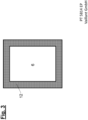
- Fig. 3 shows a highly simplified top view of a freestanding heat pump.
- the inner housing section 6 is surrounded by an external adsorber 12 on all four sides, each of which is open at the top.
Landscapes
- Chemical & Material Sciences (AREA)
- Analytical Chemistry (AREA)
- Organic Chemistry (AREA)
- Chemical Kinetics & Catalysis (AREA)
- Engineering & Computer Science (AREA)
- Physics & Mathematics (AREA)
- Mechanical Engineering (AREA)
- Thermal Sciences (AREA)
- General Engineering & Computer Science (AREA)
- Inorganic Chemistry (AREA)
- Separation Of Gases By Adsorption (AREA)
- Compressor (AREA)
Claims (12)
- Dispositif destiné à la mise en œuvre sûre d'un processus à cycle thermodynamique (1) tournant à gauche au moyen d'un fluide de travail inflammable qui est guidé dans un circuit de fluide de travail fermé et hermétiquement étanche, présentant- au moins un compresseur (2) pour un fluide de travail,- au moins un équipement de détente (4) pour un fluide de travail,- au moins deux échangeurs de chaleur (3, 5) pour un fluide de travail avec respectivement au moins deux raccords (7, 8, 9, 10) pour des fluides d'échangeur de chaleur,- un boîtier intérieur (6) qui comprend tous les équipements raccordés au niveau de la circulation de fluide de travail fermé et qui peut comprendre d'autres équipements,- au moins un adsorbeur extérieur (12) qui se raccorde directement à au boîtier intérieur (6) et recouvre au moins un côté du boîtier intérieur (6) et y est connecté,- l'adsorbeur extérieur (12) présente une ouverture de sortie (15) pour du gaz ne pouvant pas être fermée,- le boîtier intérieur (6) présente au moins une ouverture pour du gaz ainsi que, suite à cette ouverture, une zone d'admission (14) pour du gaz dans l'adsorbeur extérieur (12), dans lequel- l'adsorbeur extérieur (12) présente à la fois un adsorbant de gaz pour du gaz inflammable traversant avec du fluide de travail ainsi qu'au moins un adsorbant de bruit pour bruits de structure et aériens,- l'adsorbeur extérieur (12) présente un lit d'adsorbant (123) en tant qu'adsorbant de gaz,
au moins un tapis de sol lourd souple (122) en tant que limitation de lit et au moins une couche d'insonorisation (121) vers le boîtier (6),- le lit d'adsorbant (123) présente sur deux côtés respectivement un tapis de sol lourd souple (122) en tant que limitation de lit,- le lit d'adsorbant (123) est formé de billes ou pellets, et le tapis de sol lourd souple (122) est si souple que les billes ou pellets peuvent s'enfoncer dans le tapis de sol lourd souple (122). - Dispositif selon la revendication 1, caractérisé en ce que le tapis de sol lourd souple (122) permet d'enfoncer les billes ou pellets du lit d'adsorbant (123) de plus de la moitié du diamètre de particule.
- Dispositif selon l'une quelconque des revendications 1 ou 2, caractérisé en ce que le tapis de sol lourd souple (122) est constitué de silicone.
- Dispositif selon l'une quelconque des revendications 1 à 3, caractérisé en ce que l'adsorbeur extérieur (12) présente au moins une couche isolante (122) dont la fréquence de résonance correspond à celle de l'oscillation principale du compresseur (2) du processus à cycle (1).
- Dispositif selon l'une quelconque des revendications 1 à 4, caractérisé en ce que l'adsorbeur extérieur (12) est formé d'une première couche isolante (121) qui repose directement contre le boîtier intérieur (6), puis d'un tapis de sol lourd (122), puis d'un lit d'adsorbant (123), puis d'un tapis de sol lourd (122) supplémentaire, puis d'une couche isolante (121) supplémentaire, puis d'une paroi de boîtier extérieure.
- Dispositif selon l'une quelconque des revendications 1 à 5, caractérisé en ce que respectivement un adsorbant extérieur (12) est prévu sur au moins deux côtés du boîtier intérieur (6).
- Dispositif selon la revendication 6, caractérisé en ce que respectivement un adsorbant extérieur (12) est prévu sur au moins trois côtés du boîtier intérieur (6).
- Dispositif selon la revendication 6, caractérisé en ce que respectivement un adsorbant extérieur (12) est prévu sur tous les côtés du boîtier intérieur (6).
- Dispositif selon l'une quelconque des revendications 1 à 8, caractérisé en ce que la zone d'admission (14) de l'adsorbeur extérieur (12) est disposée en bas dans le boîtier intérieur (6), et le lit d'adsorbant (123) est maintenu par un tamis (11).
- Dispositif selon l'une quelconque des revendications 1 à 8, caractérisé en ce que la zone d'admission de l'adsorbeur extérieur (12) est disposée en haut dans le boîtier intérieur (6), et le lit d'adsorbant (123) est maintenu par un tamis (11).
- Dispositif selon l'une quelconque des revendications 1 à 10, caractérisé en ce que le lit d'adsorbant (123) pour du gaz est constitué de charbon actif.
- Dispositif selon l'une quelconque des revendications 1 à 11, caractérisé en ce que les billes ou pellets du lit d'adsorbant (123) présentent une plage de diamètres entre 0,5 et 10 millimètres et un rapport longueur/diamètre entre 1 et 20.
Priority Applications (2)
| Application Number | Priority Date | Filing Date | Title |
|---|---|---|---|
| EP20211245.4A EP4008979B1 (fr) | 2020-12-02 | 2020-12-02 | Dispositif pour effectuer en toute sécurité un cycle thermodynamique du sens anti-horaire |
| ES20211245T ES3037268T3 (en) | 2020-12-02 | 2020-12-02 | Device for safely carrying out a left-turning thermodynamic cycle |
Applications Claiming Priority (1)
| Application Number | Priority Date | Filing Date | Title |
|---|---|---|---|
| EP20211245.4A EP4008979B1 (fr) | 2020-12-02 | 2020-12-02 | Dispositif pour effectuer en toute sécurité un cycle thermodynamique du sens anti-horaire |
Publications (2)
| Publication Number | Publication Date |
|---|---|
| EP4008979A1 EP4008979A1 (fr) | 2022-06-08 |
| EP4008979B1 true EP4008979B1 (fr) | 2025-05-21 |
Family
ID=73694845
Family Applications (1)
| Application Number | Title | Priority Date | Filing Date |
|---|---|---|---|
| EP20211245.4A Active EP4008979B1 (fr) | 2020-12-02 | 2020-12-02 | Dispositif pour effectuer en toute sécurité un cycle thermodynamique du sens anti-horaire |
Country Status (2)
| Country | Link |
|---|---|
| EP (1) | EP4008979B1 (fr) |
| ES (1) | ES3037268T3 (fr) |
Families Citing this family (9)
| Publication number | Priority date | Publication date | Assignee | Title |
|---|---|---|---|---|
| DE102022130478A1 (de) | 2022-11-17 | 2024-05-23 | Vaillant Gmbh | Feuchtemanagement in einem Wärmepumpengehäuse |
| DE102022132792A1 (de) | 2022-12-09 | 2024-06-20 | Vaillant Gmbh | Adsorberpartitionierung |
| DE102022132781A1 (de) | 2022-12-09 | 2024-06-20 | Vaillant Gmbh | Adsorber mit Leitelementen |
| DE102022132800A1 (de) | 2022-12-09 | 2024-06-20 | Vaillant Gmbh | Adsorptionsvorrichtung |
| DE102023100552A1 (de) | 2023-01-12 | 2024-07-18 | Vaillant Gmbh | Störgaserkennung innen aufgestellter Wärmepumpen mit Sorptionsmodul |
| DE102023100554A1 (de) | 2023-01-12 | 2024-07-18 | Vaillant Gmbh | VOC-Vorhersage in einem Adsorber |
| DE102023114838A1 (de) | 2023-06-06 | 2024-12-12 | Vaillant Gmbh | Adsorber-Pendel in einem Kältekreisgehäuse |
| DE102023122396A1 (de) | 2023-08-22 | 2025-02-27 | Vaillant Gmbh | Modularer Aktivkohlebehälter für ein Kältemittel |
| DE102024136899A1 (de) | 2024-12-10 | 2026-06-11 | Vaillant Gmbh | Sorptionsschleuse für ein Kältekreisgehäuse |
Family Cites Families (8)
| Publication number | Priority date | Publication date | Assignee | Title |
|---|---|---|---|---|
| DE19525064C1 (de) | 1995-07-10 | 1996-08-01 | Joachim Dr Ing Paul | Kältemaschine |
| JP2002058950A (ja) * | 2000-08-22 | 2002-02-26 | Hitachi Plant Eng & Constr Co Ltd | 有害ガス換気吸収装置 |
| DE102011116863A1 (de) | 2011-10-25 | 2013-04-25 | Fraunhofer-Gesellschaft zur Förderung der angewandten Forschung e.V. | Verfahren zur Sicherung einer Vorrichtung für einen thermodynamischen Kreisprozess und abgesicherte Vorrichtung für einen thermodynamischen Kreisprozess |
| WO2015032905A1 (fr) | 2013-09-05 | 2015-03-12 | Holger König | Procédé permettant d'empêcher une fuite d'un contenant et contenant pourvu d'un dispositif anti-fuite |
| DK3106780T3 (en) | 2015-06-17 | 2018-02-26 | Vaillant Gmbh | HEAT PUMP SYSTEM |
| CN106679238A (zh) * | 2017-01-06 | 2017-05-17 | 美的集团股份有限公司 | 隔音材料、压缩机以及空调 |
| EP3693683B1 (fr) * | 2019-02-06 | 2026-01-28 | Vaillant GmbH | Barrière de diffusion au moyen de couches de protection |
| CN110285495B (zh) * | 2019-06-28 | 2021-09-28 | 广东美的制冷设备有限公司 | 一种隔振吸音装置及空调室外机 |
-
2020
- 2020-12-02 EP EP20211245.4A patent/EP4008979B1/fr active Active
- 2020-12-02 ES ES20211245T patent/ES3037268T3/es active Active
Also Published As
| Publication number | Publication date |
|---|---|
| ES3037268T3 (en) | 2025-09-30 |
| EP4008979A1 (fr) | 2022-06-08 |
Similar Documents
| Publication | Publication Date | Title |
|---|---|---|
| EP4008979A1 (fr) | Dispositif pour effectuer en toute sécurité un cycle thermodynamique du sens anti-horaire | |
| EP3581861B1 (fr) | Sorption du fluide | |
| EP3748257B1 (fr) | Dispositif pour la performance sûre d'un procédé circulaire thermodynamique à rotation à gauche au moyen d'un fluide de travail inflammable avec adsorption de fluide | |
| EP3578895B1 (fr) | Dispositif et procédé pour le rinçage sûr et économique d'une enceinte | |
| EP3486582A1 (fr) | Détection des fuites au moyen de capacité adsorbante | |
| EP3693683B1 (fr) | Barrière de diffusion au moyen de couches de protection | |
| EP3486564B1 (fr) | DISPOSITIF POUR UNE MISE EN OEUVRE SÉCURITAIRE D'UN PROCESSUS DE RANKINE CLAUSIUS THERMODYNAMIQUE À COMMUTATION GAUCHE
BASÉ SUR UNE ADSORPTION DE FLUIDE DE TRAVAIL À REFOULEMENT DE GAZ INERTE | |
| EP3705823B1 (fr) | Dispositif pour une intervention de service en toute sécurité pour un boîtier et procédé d'ouverture du boîtier. | |
| EP3543629B1 (fr) | Boîtier étanche aux fuites pour un processus cyclique | |
| EP3106780B1 (fr) | Installation de pompes à chaleur | |
| DE102019114738A1 (de) | Fluidadsorption | |
| DE102019124531A1 (de) | Sicherheitsspülvorrichtung für eine Wärmepumpe | |
| EP3693687B1 (fr) | Refroidissement d'adsorbant | |
| DE102021111808A1 (de) | Adsorber-Regeneration mit VOC-Abreicherung | |
| DE102019121496A1 (de) | Sicherheitsspülvorrichtung für eine Wärmepumpe | |
| EP3657104A1 (fr) | Pièces moulées pour pompes à chaleur | |
| EP4575332A1 (fr) | Adaptateur encapsulé pour pompe à chaleur divisée | |
| EP3647684B1 (fr) | Zone de sécurité du condenseur | |
| EP3486575B1 (fr) | Dispositif et procédé d'évacuation de sécurité du flux de travail | |
| DE102019118977A1 (de) | Adsorberkühlung | |
| EP3647685B1 (fr) | Dispositif | |
| EP3792571B1 (fr) | Conduites de raccordement d'une pompe à chaleur bibloc | |
| EP3492846B1 (fr) | Dispositif pour effectuer en toute sécurité un cycle de rankine thermodynamique en virage à gauche et sa vidange et son remplissage en toute sécurité au moyen d'un fluide de travail inflammable et procédé pour vider en toute sécurité un fluide de travail inflammable | |
| DE102019108367A1 (de) | Außen aufgestellte Wärmepumpe | |
| EP3712531A1 (fr) | Dispositif de rinçage de sécurité pour une pompe à chaleur |
Legal Events
| Date | Code | Title | Description |
|---|---|---|---|
| PUAI | Public reference made under article 153(3) epc to a published international application that has entered the european phase |
Free format text: ORIGINAL CODE: 0009012 |
|
| STAA | Information on the status of an ep patent application or granted ep patent |
Free format text: STATUS: THE APPLICATION HAS BEEN PUBLISHED |
|
| AK | Designated contracting states |
Kind code of ref document: A1 Designated state(s): AL AT BE BG CH CY CZ DE DK EE ES FI FR GB GR HR HU IE IS IT LI LT LU LV MC MK MT NL NO PL PT RO RS SE SI SK SM TR |
|
| STAA | Information on the status of an ep patent application or granted ep patent |
Free format text: STATUS: REQUEST FOR EXAMINATION WAS MADE |
|
| 17P | Request for examination filed |
Effective date: 20221206 |
|
| RBV | Designated contracting states (corrected) |
Designated state(s): AL AT BE BG CH CY CZ DE DK EE ES FI FR GB GR HR HU IE IS IT LI LT LU LV MC MK MT NL NO PL PT RO RS SE SI SK SM TR |
|
| STAA | Information on the status of an ep patent application or granted ep patent |
Free format text: STATUS: EXAMINATION IS IN PROGRESS |
|
| 17Q | First examination report despatched |
Effective date: 20231128 |
|
| GRAP | Despatch of communication of intention to grant a patent |
Free format text: ORIGINAL CODE: EPIDOSNIGR1 |
|
| STAA | Information on the status of an ep patent application or granted ep patent |
Free format text: STATUS: GRANT OF PATENT IS INTENDED |
|
| INTG | Intention to grant announced |
Effective date: 20250107 |
|
| GRAS | Grant fee paid |
Free format text: ORIGINAL CODE: EPIDOSNIGR3 |
|
| GRAA | (expected) grant |
Free format text: ORIGINAL CODE: 0009210 |
|
| STAA | Information on the status of an ep patent application or granted ep patent |
Free format text: STATUS: THE PATENT HAS BEEN GRANTED |
|
| AK | Designated contracting states |
Kind code of ref document: B1 Designated state(s): AL AT BE BG CH CY CZ DE DK EE ES FI FR GB GR HR HU IE IS IT LI LT LU LV MC MK MT NL NO PL PT RO RS SE SI SK SM TR |
|
| REG | Reference to a national code |
Ref country code: GB Ref legal event code: FG4D Free format text: NOT ENGLISH |
|
| REG | Reference to a national code |
Ref country code: CH Ref legal event code: EP |
|
| REG | Reference to a national code |
Ref country code: DE Ref legal event code: R096 Ref document number: 502020011087 Country of ref document: DE |
|
| REG | Reference to a national code |
Ref country code: IE Ref legal event code: FG4D Free format text: LANGUAGE OF EP DOCUMENT: GERMAN |
|
| REG | Reference to a national code |
Ref country code: NL Ref legal event code: FP |
|
| REG | Reference to a national code |
Ref country code: ES Ref legal event code: FG2A Ref document number: 3037268 Country of ref document: ES Kind code of ref document: T3 Effective date: 20250930 |
|
| PG25 | Lapsed in a contracting state [announced via postgrant information from national office to epo] |
Ref country code: FI Free format text: LAPSE BECAUSE OF FAILURE TO SUBMIT A TRANSLATION OF THE DESCRIPTION OR TO PAY THE FEE WITHIN THE PRESCRIBED TIME-LIMIT Effective date: 20250521 Ref country code: PT Free format text: LAPSE BECAUSE OF FAILURE TO SUBMIT A TRANSLATION OF THE DESCRIPTION OR TO PAY THE FEE WITHIN THE PRESCRIBED TIME-LIMIT Effective date: 20250922 |
|
| REG | Reference to a national code |
Ref country code: LT Ref legal event code: MG9D |
|
| PG25 | Lapsed in a contracting state [announced via postgrant information from national office to epo] |
Ref country code: GR Free format text: LAPSE BECAUSE OF FAILURE TO SUBMIT A TRANSLATION OF THE DESCRIPTION OR TO PAY THE FEE WITHIN THE PRESCRIBED TIME-LIMIT Effective date: 20250822 Ref country code: NO Free format text: LAPSE BECAUSE OF FAILURE TO SUBMIT A TRANSLATION OF THE DESCRIPTION OR TO PAY THE FEE WITHIN THE PRESCRIBED TIME-LIMIT Effective date: 20250821 |
|
| PG25 | Lapsed in a contracting state [announced via postgrant information from national office to epo] |
Ref country code: PL Free format text: LAPSE BECAUSE OF FAILURE TO SUBMIT A TRANSLATION OF THE DESCRIPTION OR TO PAY THE FEE WITHIN THE PRESCRIBED TIME-LIMIT Effective date: 20250521 |
|
| PG25 | Lapsed in a contracting state [announced via postgrant information from national office to epo] |
Ref country code: BG Free format text: LAPSE BECAUSE OF FAILURE TO SUBMIT A TRANSLATION OF THE DESCRIPTION OR TO PAY THE FEE WITHIN THE PRESCRIBED TIME-LIMIT Effective date: 20250521 |
|
| PG25 | Lapsed in a contracting state [announced via postgrant information from national office to epo] |
Ref country code: HR Free format text: LAPSE BECAUSE OF FAILURE TO SUBMIT A TRANSLATION OF THE DESCRIPTION OR TO PAY THE FEE WITHIN THE PRESCRIBED TIME-LIMIT Effective date: 20250521 |
|
| PG25 | Lapsed in a contracting state [announced via postgrant information from national office to epo] |
Ref country code: RS Free format text: LAPSE BECAUSE OF FAILURE TO SUBMIT A TRANSLATION OF THE DESCRIPTION OR TO PAY THE FEE WITHIN THE PRESCRIBED TIME-LIMIT Effective date: 20250821 |
|
| PG25 | Lapsed in a contracting state [announced via postgrant information from national office to epo] |
Ref country code: IS Free format text: LAPSE BECAUSE OF FAILURE TO SUBMIT A TRANSLATION OF THE DESCRIPTION OR TO PAY THE FEE WITHIN THE PRESCRIBED TIME-LIMIT Effective date: 20250921 |
|
| PG25 | Lapsed in a contracting state [announced via postgrant information from national office to epo] |
Ref country code: LV Free format text: LAPSE BECAUSE OF FAILURE TO SUBMIT A TRANSLATION OF THE DESCRIPTION OR TO PAY THE FEE WITHIN THE PRESCRIBED TIME-LIMIT Effective date: 20250521 |
|
| PGFP | Annual fee paid to national office [announced via postgrant information from national office to epo] |
Ref country code: GB Payment date: 20251128 Year of fee payment: 6 |
|
| PG25 | Lapsed in a contracting state [announced via postgrant information from national office to epo] |
Ref country code: SM Free format text: LAPSE BECAUSE OF FAILURE TO SUBMIT A TRANSLATION OF THE DESCRIPTION OR TO PAY THE FEE WITHIN THE PRESCRIBED TIME-LIMIT Effective date: 20250521 Ref country code: DK Free format text: LAPSE BECAUSE OF FAILURE TO SUBMIT A TRANSLATION OF THE DESCRIPTION OR TO PAY THE FEE WITHIN THE PRESCRIBED TIME-LIMIT Effective date: 20250521 |
|
| PGFP | Annual fee paid to national office [announced via postgrant information from national office to epo] |
Ref country code: NL Payment date: 20251128 Year of fee payment: 6 Ref country code: FR Payment date: 20251223 Year of fee payment: 6 |
|
| PG25 | Lapsed in a contracting state [announced via postgrant information from national office to epo] |
Ref country code: CZ Free format text: LAPSE BECAUSE OF FAILURE TO SUBMIT A TRANSLATION OF THE DESCRIPTION OR TO PAY THE FEE WITHIN THE PRESCRIBED TIME-LIMIT Effective date: 20250521 |
|
| PG25 | Lapsed in a contracting state [announced via postgrant information from national office to epo] |
Ref country code: EE Free format text: LAPSE BECAUSE OF FAILURE TO SUBMIT A TRANSLATION OF THE DESCRIPTION OR TO PAY THE FEE WITHIN THE PRESCRIBED TIME-LIMIT Effective date: 20250521 |
|
| PG25 | Lapsed in a contracting state [announced via postgrant information from national office to epo] |
Ref country code: SK Free format text: LAPSE BECAUSE OF FAILURE TO SUBMIT A TRANSLATION OF THE DESCRIPTION OR TO PAY THE FEE WITHIN THE PRESCRIBED TIME-LIMIT Effective date: 20250521 Ref country code: RO Free format text: LAPSE BECAUSE OF FAILURE TO SUBMIT A TRANSLATION OF THE DESCRIPTION OR TO PAY THE FEE WITHIN THE PRESCRIBED TIME-LIMIT Effective date: 20250521 |
|
| REG | Reference to a national code |
Ref country code: DE Ref legal event code: R097 Ref document number: 502020011087 Country of ref document: DE |
|
| PLBE | No opposition filed within time limit |
Free format text: ORIGINAL CODE: 0009261 |
|
| STAA | Information on the status of an ep patent application or granted ep patent |
Free format text: STATUS: NO OPPOSITION FILED WITHIN TIME LIMIT |
|
| REG | Reference to a national code |
Ref country code: CH Ref legal event code: L10 Free format text: ST27 STATUS EVENT CODE: U-0-0-L10-L00 (AS PROVIDED BY THE NATIONAL OFFICE) Effective date: 20260402 |
|
| PGFP | Annual fee paid to national office [announced via postgrant information from national office to epo] |
Ref country code: ES Payment date: 20260102 Year of fee payment: 6 |
|
| PGFP | Annual fee paid to national office [announced via postgrant information from national office to epo] |
Ref country code: IT Payment date: 20251229 Year of fee payment: 6 |
|
| 26N | No opposition filed |
Effective date: 20260224 |
|
| PG25 | Lapsed in a contracting state [announced via postgrant information from national office to epo] |
Ref country code: LT Free format text: LAPSE BECAUSE OF FAILURE TO SUBMIT A TRANSLATION OF THE DESCRIPTION OR TO PAY THE FEE WITHIN THE PRESCRIBED TIME-LIMIT Effective date: 20250521 |
|
| PG25 | Lapsed in a contracting state [announced via postgrant information from national office to epo] |
Ref country code: MC Free format text: LAPSE BECAUSE OF FAILURE TO SUBMIT A TRANSLATION OF THE DESCRIPTION OR TO PAY THE FEE WITHIN THE PRESCRIBED TIME-LIMIT Effective date: 20250521 |
|
| REG | Reference to a national code |
Ref country code: CH Ref legal event code: H13 Free format text: ST27 STATUS EVENT CODE: U-0-0-H10-H13 (AS PROVIDED BY THE NATIONAL OFFICE) Effective date: 20260723 |
|
| PG25 | Lapsed in a contracting state [announced via postgrant information from national office to epo] |
Ref country code: SE Free format text: LAPSE BECAUSE OF FAILURE TO SUBMIT A TRANSLATION OF THE DESCRIPTION OR TO PAY THE FEE WITHIN THE PRESCRIBED TIME-LIMIT Effective date: 20250521 |