EP4009003A1 - Système de capteur et méthode de mesure d'une valeur de procédé d'un système physique - Google Patents
Système de capteur et méthode de mesure d'une valeur de procédé d'un système physique Download PDFInfo
- Publication number
- EP4009003A1 EP4009003A1 EP20211276.9A EP20211276A EP4009003A1 EP 4009003 A1 EP4009003 A1 EP 4009003A1 EP 20211276 A EP20211276 A EP 20211276A EP 4009003 A1 EP4009003 A1 EP 4009003A1
- Authority
- EP
- European Patent Office
- Prior art keywords
- sense signals
- acquired
- sub
- state
- sense
- Prior art date
- Legal status (The legal status is an assumption and is not a legal conclusion. Google has not performed a legal analysis and makes no representation as to the accuracy of the status listed.)
- Granted
Links
Images





Classifications
-
- G—PHYSICS
- G01—MEASURING; TESTING
- G01D—MEASURING NOT SPECIALLY ADAPTED FOR A SPECIFIC VARIABLE; ARRANGEMENTS FOR MEASURING TWO OR MORE VARIABLES NOT COVERED IN A SINGLE OTHER SUBCLASS; TARIFF METERING APPARATUS; MEASURING OR TESTING NOT OTHERWISE PROVIDED FOR
- G01D3/00—Indicating or recording apparatus with provision for the special purposes referred to in the subgroups
- G01D3/02—Indicating or recording apparatus with provision for the special purposes referred to in the subgroups with provision for altering or correcting the law of variation
-
- G—PHYSICS
- G05—CONTROLLING; REGULATING
- G05B—CONTROL OR REGULATING SYSTEMS IN GENERAL; FUNCTIONAL ELEMENTS OF SUCH SYSTEMS; MONITORING OR TESTING ARRANGEMENTS FOR SUCH SYSTEMS OR ELEMENTS
- G05B13/00—Adaptive control systems, i.e. systems automatically adjusting themselves to have a performance which is optimum according to some preassigned criterion
- G05B13/02—Adaptive control systems, i.e. systems automatically adjusting themselves to have a performance which is optimum according to some preassigned criterion electric
- G05B13/04—Adaptive control systems, i.e. systems automatically adjusting themselves to have a performance which is optimum according to some preassigned criterion electric involving the use of models or simulators
- G05B13/048—Adaptive control systems, i.e. systems automatically adjusting themselves to have a performance which is optimum according to some preassigned criterion electric involving the use of models or simulators using a predictor
-
- G—PHYSICS
- G01—MEASURING; TESTING
- G01D—MEASURING NOT SPECIALLY ADAPTED FOR A SPECIFIC VARIABLE; ARRANGEMENTS FOR MEASURING TWO OR MORE VARIABLES NOT COVERED IN A SINGLE OTHER SUBCLASS; TARIFF METERING APPARATUS; MEASURING OR TESTING NOT OTHERWISE PROVIDED FOR
- G01D3/00—Indicating or recording apparatus with provision for the special purposes referred to in the subgroups
- G01D3/08—Indicating or recording apparatus with provision for the special purposes referred to in the subgroups with provision for safeguarding the apparatus, e.g. against abnormal operation, against breakdown
-
- G—PHYSICS
- G01—MEASURING; TESTING
- G01D—MEASURING NOT SPECIALLY ADAPTED FOR A SPECIFIC VARIABLE; ARRANGEMENTS FOR MEASURING TWO OR MORE VARIABLES NOT COVERED IN A SINGLE OTHER SUBCLASS; TARIFF METERING APPARATUS; MEASURING OR TESTING NOT OTHERWISE PROVIDED FOR
- G01D5/00—Mechanical means for transferring the output of a sensing member; Means for converting the output of a sensing member to another variable where the form or nature of the sensing member does not constrain the means for converting; Transducers not specially adapted for a specific variable
- G01D5/12—Mechanical means for transferring the output of a sensing member; Means for converting the output of a sensing member to another variable where the form or nature of the sensing member does not constrain the means for converting; Transducers not specially adapted for a specific variable using electric or magnetic means
- G01D5/14—Mechanical means for transferring the output of a sensing member; Means for converting the output of a sensing member to another variable where the form or nature of the sensing member does not constrain the means for converting; Transducers not specially adapted for a specific variable using electric or magnetic means influencing the magnitude of a current or voltage
- G01D5/142—Mechanical means for transferring the output of a sensing member; Means for converting the output of a sensing member to another variable where the form or nature of the sensing member does not constrain the means for converting; Transducers not specially adapted for a specific variable using electric or magnetic means influencing the magnitude of a current or voltage using Hall-effect devices
- G01D5/145—Mechanical means for transferring the output of a sensing member; Means for converting the output of a sensing member to another variable where the form or nature of the sensing member does not constrain the means for converting; Transducers not specially adapted for a specific variable using electric or magnetic means influencing the magnitude of a current or voltage using Hall-effect devices influenced by the relative movement between the Hall device and magnetic fields
-
- G—PHYSICS
- G05—CONTROLLING; REGULATING
- G05B—CONTROL OR REGULATING SYSTEMS IN GENERAL; FUNCTIONAL ELEMENTS OF SUCH SYSTEMS; MONITORING OR TESTING ARRANGEMENTS FOR SUCH SYSTEMS OR ELEMENTS
- G05B13/00—Adaptive control systems, i.e. systems automatically adjusting themselves to have a performance which is optimum according to some preassigned criterion
- G05B13/02—Adaptive control systems, i.e. systems automatically adjusting themselves to have a performance which is optimum according to some preassigned criterion electric
- G05B13/04—Adaptive control systems, i.e. systems automatically adjusting themselves to have a performance which is optimum according to some preassigned criterion electric involving the use of models or simulators
- G05B13/042—Adaptive control systems, i.e. systems automatically adjusting themselves to have a performance which is optimum according to some preassigned criterion electric involving the use of models or simulators in which a parameter or coefficient is automatically adjusted to optimise the performance
-
- G—PHYSICS
- G05—CONTROLLING; REGULATING
- G05B—CONTROL OR REGULATING SYSTEMS IN GENERAL; FUNCTIONAL ELEMENTS OF SUCH SYSTEMS; MONITORING OR TESTING ARRANGEMENTS FOR SUCH SYSTEMS OR ELEMENTS
- G05B23/00—Testing or monitoring of control systems or parts thereof
- G05B23/02—Electric testing or monitoring
- G05B23/0205—Electric testing or monitoring by means of a monitoring system capable of detecting and responding to faults
- G05B23/0218—Electric testing or monitoring by means of a monitoring system capable of detecting and responding to faults characterised by the fault detection method dealing with either existing or incipient faults
- G05B23/0221—Preprocessing measurements, e.g. data collection rate adjustment; Standardization of measurements; Time series or signal analysis, e.g. frequency analysis or wavelets; Trustworthiness of measurements; Indexes therefor; Measurements using easily measured parameters to estimate parameters difficult to measure; Virtual sensor creation; De-noising; Sensor fusion; Unconventional preprocessing inherently present in specific fault detection methods like PCA-based methods
-
- G—PHYSICS
- G05—CONTROLLING; REGULATING
- G05B—CONTROL OR REGULATING SYSTEMS IN GENERAL; FUNCTIONAL ELEMENTS OF SUCH SYSTEMS; MONITORING OR TESTING ARRANGEMENTS FOR SUCH SYSTEMS OR ELEMENTS
- G05B23/00—Testing or monitoring of control systems or parts thereof
- G05B23/02—Electric testing or monitoring
- G05B23/0205—Electric testing or monitoring by means of a monitoring system capable of detecting and responding to faults
- G05B23/0218—Electric testing or monitoring by means of a monitoring system capable of detecting and responding to faults characterised by the fault detection method dealing with either existing or incipient faults
- G05B23/0243—Electric testing or monitoring by means of a monitoring system capable of detecting and responding to faults characterised by the fault detection method dealing with either existing or incipient faults model based detection method, e.g. first-principles knowledge model
- G05B23/0254—Electric testing or monitoring by means of a monitoring system capable of detecting and responding to faults characterised by the fault detection method dealing with either existing or incipient faults model based detection method, e.g. first-principles knowledge model based on a quantitative model, e.g. mathematical relationships between inputs and outputs; functions: observer, Kalman filter, residual calculation, Neural Networks
Definitions
- the invention relates to a sensor system for measuring a process value of a physical system, such as a position of a position indicator of a kinematic system, particularly a highly dynamic system.
- the invention also relates to a method for measuring a process value of a physical system, such as a position of a position indicator of a dynamic kinematic system, particularly a highly dynamic system.
- Sensor systems for measuring a position (process value) of a rotating or linearly moving position indicator are generally known, in which the position information to be obtained is represented by sine and cosine shaped varying raw sensor signals. Possible implementations include e.g. the measurement of magnetic field components of a magnetic induction field of a permanent magnet at suitable locations in space. The searched position information may be obtained by applying the arctangent to the measured sine and cosine shaped sensor signal values.
- a fundamental difficulty with these methods is that a non-ideal arrangement of the position indicator and the sensor chip leads to distortions of the raw signals, namely that these no longer have the pure sine and cosine shape and thus lead to an inaccurate determination of the position.
- a position sensing system is responsive to external fields (e.g. the earth's magnetic field in the case of a position indicator based on permanent magnets). Without countermeasures, these additional field components cannot be distinguished from the useful field so that the external fields restrict the accuracy of the position measuring system.
- external fields e.g. the earth's magnetic field in the case of a position indicator based on permanent magnets.
- a fundamental challenge for position measuring systems is their long-term stability, i.e. an initially sufficiently accurate calibration of the dynamic system changes over time, e.g. by mechanical displacement of the components relative to one another or by drifting of electronic sensor properties.
- a fault-tolerant system and method for ascertaining the measurement quality of such dynamic physical systems during normal operation are described in US 10,557,722 B2 , which is incorporated herein in its entirety by reference, thus improving the long-term stability of such measuring systems.
- the proposed solution for determining the position of a position indicator was based on the finding that the sensor measurement values supplied by the sensors can be represented as a measurement vector, i.e.
- This orbit can - under ideal conditions - be projected onto a circle or a circular arc by means of a linear mapping, i.e. each position of the position indicator corresponds to a point on the orbit in the abstract space of the signal vectors which is unambiguously assigned to a point on the circle or arc.
- Non-ideal conditions for example non-ideal properties of the position indicator, which can be particularly the case with magnets, or an insufficient number of sensors or the use of non-optimally selected calibration positions, cause deviations from the circular shape.
- the linear mapping can be represented as a matrix-vector operation and can be determined using standard methods of linear algebra. Each measurement vector is projected onto a 2-component pointer vector, the tip of which approximates a circular arc, wherein the direction of the 2-component vector corresponds to the position of the position indicator.
- the aforementioned sensor system and method for measuring the position of the position indicator require concurrent instantaneous measurement of all sensor signals to be subjected to the matrix-vector multiplication to obtain the pointer vector at this instant.
- the electronic implementation is challenging and inevitably leads to high processor clock rates for large bandwidths.
- the use of parallel analog-to-digital converters (ADC) for concurrent uniform sampling of the individual sensor signals is cumbersome with respect to stability issues.
- the actual signal processing consists of the matrix-vector multiplication as mentioned above.
- the term “approximately” or “essentially” indicates a range of tolerance which the skilled person in the field in question considers to be normal.
- the term “approximately” or “essentially” is to be understood as a tolerance range of the referred quantity of up to a maximum of +/-20 %, preferably up to a maximum of +/-10 %.
- a sensor system for measuring a process value e.g. position, velocity, acceleration of a position indicator
- a physical system in particular a dynamic system comprising moving/rotating components including the position indicator for example
- a process value e.g. position, velocity, acceleration of a position indicator
- a physical system in particular a dynamic system comprising moving/rotating components including the position indicator for example
- a plurality of sensors e.g. Hall sensors in the case of measuring a magnetic field indicating a characteristic of the physical system to be monitored
- each sensor is configured to generate a sense signal (particularly e.g. a continuous-time sense signal) as a function of the process value at a given time
- a system state corrector configured to determine an actual system state of the physical system at a given state update cycle, wherein the system state comprises the process value at the given state update cycle and at least a first order derivative of the process value (i.e.
- a system state predictor configured to determine a predicted system state of the physical system at a given prediction cycle from a previous system state at a previous state update cycle; a sense signal predictor configured to determine predicted sense signals at the given prediction cycle from the predicted system state by applying a first operation to the predicted system state using a sense signal model (e.g. a signal model matrix) of the physical system for predicting the sense signals; wherein the system state corrector is further configured to determine the actual system state at the given state update cycle by applying a second operation (e.g. a Kalman filter operation) to the predicted system state according to an error signal, the error signal being representative of the difference between a set of acquired sense signals acquired from the sense signals each at the given prediction cycle and the corresponding predicted sense signals for each of the acquired sense signals.
- a second operation e.g. a Kalman filter operation
- the process value information (e.g. position information of a position indicator) encoded in the sense signals is used to control a digital representation of the physical system (e.g. a rotating physical system such as a motor/generator shaft and the like) in a phase-locked loop (PLL).
- the system state i.e. the state of the digital representation of the physical system, is updated in a two-stage-process: (i) The previous system state at the previous state update cycle is used to predict the system state at the given prediction cycle, and (ii) using the set of actually acquired (measured) sense signals, the predicted system state is then corrected accordingly to obtain the system state at the actual state update cycle.
- This process may be successfully and effectively applied to the case of sensor arrangements providing redundant measurements or sense signals which are distorted by offsets and/or amplitude mismatches due to non-idealities.
- the sense signal model modelling the measurement process of the physical system is used to be applied to the predicted system state in the first operation.
- the sense signal model may be represented as a model matrix containing information about the measurement process of the sensors in the dynamic physical system. This information may be acquired (once) in a separate calibration process. From this calibration process, the sense signal model and characteristics of possibly present higher harmonics may be identified. This facilitates an accurate and fast prediction of the sense signals form the predicted system state.
- the second operation which, without being limited thereto, may be a Kalman filter operation adopted to eventually evaluate the corrected system state from the error signal, i.e. the difference between the set of the predicted sense signals and the corresponding acquired sense signals each at the given prediction cycle.
- the set of the acquired and predicted sense signals may vary in number between different state update cycles, for example the signal set may include only one single acquired sense signal along with its corresponding predicted sense signal at the same prediction cycle, or it may include more than only one acquired sense signal along with their corresponding predicted sense signals at different prediction cycles one by one.
- each pair of corresponding signals i.e. one of the acquired sense signals along with its corresponding predicted sense signal, is always related to the same prediction cycle, i.e. the same time instant.
- the second operation will accurately update the system state at each state update cycle from the previous system state at the previous state update cycle.
- the system state corrector, the system state predictor, and the sense signal predictor may be implemented using a digital processing unit.
- the digital processing unit may be any circuit configuration capable of receiving and outputting a signal. Therefore, the digital processing unit may be any hardware and/or software configuration capable of operating on the received signal(s), performing an operation on the received signal(s), thereby determining the actual system state, and outputting the determined system state.
- the digital processing unit may be a digital signal processor (DPS), microprocessor ( ⁇ P), microcontroller ( ⁇ C) and the like, however, without being limited thereto.
- the sensor system facilitates the measurement of the process value of a (highly) dynamic physical system with high accuracy and low susceptibility to non-idealities such as interference due to noise, temperature, and external fields, resulting in a significantly improved operational robustness and long-term-stability of the sensor system.
- the set of the acquired sense signals may comprise one single sense signal from one of the sensors, a plurality of sense signals from more than one but less than all of the sensors, or a plurality of sense signals from all of the sensors.
- the set of the acquired sense signals comprises one sense signal from one of the sensors, or a plurality of sense signals from more than one but less than all of the sensors such that the set of the acquired sense signals contains only a partial information of the system state, wherein the partial information is not sufficient to deterministically identify the system state at the state update cycle.
- the second operation being applied to the predicted system state using the error signal still provides for the update of the system state at the state update cycle.
- a situation, in which the information (herein also referred to as partial information ) conveyed by the set of the acquired sense signals during a state update cycle does not allow a deterministic identification of the actual system state, may arise when the set of the acquired sense signals only comprises one single acquired sense signal per one state update cycle, or, for example, in the case of a rotating position indicator whose angular position (process value) is to be measured by the sensor system, wherein all the acquired sense signals represent the same type of position information, for example only sine or only cosine related signal information about the angular position of the position indicator, i.e. a phase difference or shift between the considered acquired sense signals which may be essentially 180°.
- the searched process value i.e. in the example above the angular position information of the rotating position indicator
- the searched process value is no longer obtainable unambiguously by applying an inverse function to the set of the acquired sense signals, e.g. the arctangent.
- such partial information may be used to determine an unambiguous position of the position indicator (i.e. a deterministic identification of the actual system state) using all the available information of the sense signals and the predicted state.
- the set of the acquired sense signals comprises sense signals from more than one or all of the sensors, wherein each of the acquired sense signals corresponds to the same given time instant, i.e. the same given prediction cycle (herein also referred to as uniform sampling ).
- all the acquired sense signals constituting the set of the acquired sense signals at the current state update cycle and consequently all the corresponding predicted sense signals relate to the same time instant and to the same prediction cycle, respectively.
- all the acquired sense signals are acquired from the sense signals (i.e. sense signals provided by the sensors) simultaneously, e.g. using a multi-channel analog-to-digital converter (ADC) providing one channel to each of those sense signals to be acquired at the same time instant.
- ADC analog-to-digital converter
- the set of the acquired sense signals comprises the sense signals of all of the provided sensors
- the simultaneous acquisition of the plurality of sense signals may become demanding, particularly if all the sense signals of all provided sensors are to be acquired simultaneously, as a clock rate of a digital processing unit becomes likewise high.
- the first operation using the sense signal model (e.g. matrix) for calculating all corresponding predicted sense signals must be performed on the entire model matrix if the entire sense signal information of all provided sensors is to be included.
- more actually acquired sense signal information during one state update cycle may improve the accuracy of the updated system state information significantly.
- the state update cycle may update the system state at an r-times faster rate r/T instead of 1/T, while during the time period T the same overall information is processed, with r being the number of sensors provided and T being the system state update period. This provides better accuracy and less latency compared to the uniform sampling case above.
- the set of the acquired sense signals comprises sense signals from more than one or all of the sensors, wherein at least two of the acquired sense signals correspond to different given time instants, i.e. different given prediction cycles within the same state update cycle (herein also referred to as non-uniform sampling ) .
- the set of the acquired sense signals may comprise acquired sense signals having been acquired at different time instants and different prediction cycles, respectively, each predicted sense signal and its associated corresponding acquired sense signal always relate to the same time instant, i.e. the same prediction cycle.
- subsequent acquisition of the sense signals is facilitated in turn allowing the use of ADCs having fewer or even only one single analog-to-digital channel leading to less thermal drift issues.
- the various sense signals may be acquired in a time-multiplexing fashion during the same state update cycle. Furthermore, it may be possible to gather more than only two acquired sense signals of different time instants and different prediction cycles, respectively, within the same state update cycle before eventually updating the system state, thus improving the information content the second operation may use for a more accurate system state update determination.
- the first and second operations may reduce significantly in terms of computational time as a reduced set of the acquired sense signals along with their corresponding predicted sense signals facilitates the omission of re-computing those mathematical terms which include only sense signal information that has not been actually acquired and respectively predicted within the current state update cycle (thus not providing any new information with respect to the previous state update cycle).
- the sense signal model used for predicting the sense signals at the given prediction cycle is represented as a model matrix having row and column entries, wherein each row may relate to the sense signal of one sensor and each row entry (i.e. the column entries of the model matrix) may refer to multiple harmonic components assessed during the calibration process
- each row may relate to the sense signal of one sensor and each row entry (i.e. the column entries of the model matrix) may refer to multiple harmonic components assessed during the calibration process
- only the rows of the model matrix corresponding to the sense signals that are actually to be predicted according to the associated and newly acquired sense signals may be included in the mathematical operations to be conducted, whereas the remaining matrix information may be simply omitted thus reducing the overall computational effort significantly for the current state update cycle.
- the prediction of each predicted sense signal depends on the entire information provided by the previous system state. Particularly, this information may comprise all the harmonic components assessed during the calibration process and contained in the model matrix for the specific sense signal to be predicted.
- the second operation (e.g. a Kalman filter operation) using the error signal, i.e. the differences between each of the acquired sense signals and the corresponding predicted sense signals, reduces to the mathematical operations using the actually acquired and predicted sense signals in the current state update cycle only.
- the signal processing speed may be increased by non-uniform sense signal acquisition and the single sense signal acquisition per prediction cycle and per state update cycle, as the corresponding first and second operations (possibly including a Kalman filter prediction and update) is inherently computationally simpler as the matrices involved are considerably smaller.
- the reduction of the computational effort is put into effect automatically within each state update cycle according to further embodiments of the invention.
- the sense signal predictor is configured to determine only the predicted sense signals corresponding to the set of acquired sense signals at the given prediction cycle.
- the set of the acquired sense signals comprises selected sense signals from more than one but less than all of the sensors, wherein, among all of the sense signals, at the prediction cycle the selected sense signals of the set of the acquired sense signals contain a more accurate information of the system state or have at least first order derivatives with a larger absolute value than the non-selected sense signals.
- the selected sense signals may be sense signals of two different sensors providing sense signals ideally having a phase difference or phase shift of approximately 90 °.
- the selected sense signals may be sense signals of those sensors providing sense signals at the current prediction cycle having a high rate of change (or the highest of all rates of change), i.e.
- the system state information contained in the set of the acquired sense signals per state update cycle is optimally improving the overall accuracy of the sensor system.
- the first and second operations constitute an extended Kalman filter or a non-linear Kalman filter.
- Kalman filters are generally well-known in many technical systems, e.g. for tracking dynamic processes by periodic measurements of sensor signals that (partly) reveal the actual dynamic state of the system.
- Using a deterministic model in addition to observing (measuring) the dynamic system it is possible to integrate the information gathered by the periodic measurements into a prediction of the system state, even for unobserved quantities.
- An integral part of a Kalman filter is the tracking of the so-called covariance of the state variable, which is used to optimally use all information (new measurements and present dynamic model state) to find the true state.
- the extended Kalman filter or non-linear Kalman filter use a nonlinear relationship between the system state or state variable(s), respectively, and the acquired sense signals which basically may be sine and cosine functions of an angle, possibly corresponding to different harmonics, of a rotating position indicator for example,
- the filter is then formulated in terms of a linearization of the constitutive nonlinear functions.
- the prediction and the correction of the state covariance is implemented by calculations which include estimates of the noise affecting the dynamic physical system and the signal measurement process.
- the first operation comprises a multi-order harmonic expansion as a function of the process value.
- the harmonic expansion comprises at least two orders, and more preferably at least three orders.
- the process value is a position of a position indicator being movable relative to the sensors.
- the position indicator may be rotatable relative to the sensors, however, without being limited thereto, i.e. a linear movement of the position indicator relative to the sensor(s) will be likewise encompassed by other embodiments of the invention.
- the position indicator may be attached to a motor/generator (drive) shaft of a motor/generator for example.
- the sensors may be magnetic sensors such as Hall elements for example, and the position indicator may be a magnet, e.g. a permanent magnet.
- the sense signals generated by the sensors essentially are harmonic signals, i.e. sine or cosine functions, possibly also comprising higher order harmonics.
- the sensor system further comprises at least one analog-to-digital converter (ADC) for quantizing at least one of the sense signals generated by the sensors and for providing the quantized sense signals as the acquired sense signals.
- ADC analog-to-digital converter
- the ADC may be s single-channel ADC being capable of converting one analog signal to a digital signal at a time. Then, in subsequent prediction cycles and/or subsequent state update cycles the selected sensor/sense signal to be converted may change to constitute the desired set of the acquired sense signals as described herein (non-uniform sampling).
- the ADC may be a multichannel ADC providing a plurality of A/D channels.
- the number of A/D channels may be equal or even higher than the number of sensors provided in the sensor system according to the invention. In this case, all sense signals of all provided sensors may be acquired simultaneously (uniform sampling).
- the ADC may be a multichannel ADC having less than the total number of sensors provided in the sensor system. Then, a subset of the sense signals of all of the provided sensors in the sensor system may be acquired simultaneously by the ADC, wherein the subset of the acquired sense signals may vary in subsequent prediction cycles and/or subsequent state update cycles (non-uniform sampling).
- a method for measuring a process value comprises at least the steps of:
- the method according to the invention facilitates the measurement of the process value of a (highly) dynamic physical system with high accuracy and low susceptibility to non-idealities such as interference due to noise, temperature, and external fields, resulting in a significantly improved operational robustness and long-term-stability of the sensor system.
- the set of the acquired sense signals used in the method according to the invention may comprise one single sense signal from one of the sensors, a plurality of sense signals from more than one but less than all of the sensors, or a plurality of sense signals from all of the sensors.
- the set of the acquired sense signals comprises sense signals from more than one or all of the sensors, wherein each of the comprised sense signals is acquired from the respective sensors at the same given time instant, i.e. at the same prediction cycle (herein also referred to as uniform sampling ) .
- the set of the acquired sense signals comprises sense signals from more than one or all of the sensors, wherein at least two of the acquired sense signals are acquired at different given time instants, i.e. at different given prediction cycles within the same state update cycle (herein also referred to as non-uniform sampling ) .
- selected sense signals from more than one but less than all of the sensors are selected to constitute the set of the acquired sense signals such that, among all of the sense signals, at the given prediction cycle the selected sense signals contain a more accurate information of the system state (e.g. sense signals having a phase difference or phase shift of approximately 90° at the given prediction cycle) or have at least first order derivatives with a larger absolute value (e.g. sense signals having a high rate of change at the given prediction cycle) than the non-selected sense signals (e.g. sense signals having a phase difference or phase shift of significantly less than 90°, such as -10° to 10° at the given prediction cycle for example, or sense signals having almost no rate of change at the given prediction cycle).
- the selection of the selected sense signals constituting the set of the acquired sense signals is performed dynamically, i.e. instantly during the operation.
- the first and second operations constitute an extended Kalman filter or a non-linear Kalman filter.
- a multi-order harmonic expansion is used as a function of the process value.
- the harmonic expansion comprises at least two orders, and more preferably at least three orders.
- a position e.g. an angular position
- a position indicator e.g. a magnet
- the sensors e.g. magnetic sensors such as Hall sensors
- Linear movements of the position indicator relative to the sensor(s) are likewise encompassed by other embodiments of the invention.
- Fig. 1 shows a functional diagram of an exemplary embodiment of a sensor system 1 for measuring a process value ⁇ ( t ) of a physical system 2 according to the invention.
- the sensors HE i are magnetic sensors, such as Hall sensors for example, to sense a magnetic field.
- the magnetic field is generated by a position indicator 7 rotatable relative to the sensors HE i as indicated by a respective arrow in Fig. 1 .
- the position indicator 7 is formed by a permanent magnet in the exemplary case having poles N(orth) and S(outh).
- the magnet may be connected to a drive shaft of a motor (not shown), e.g. an electric motor, however, without being limited thereto.
- a motor e.g. an electric motor
- the magnetic field may be generated by other means than a permanent magnet, for example by an electric current flowing through an electromagnetic coil, a solenoid, an electric conductor and the like.
- the process value ⁇ ( t ) being measured by the sensor system 1 of Fig. 1 is an angular position of the position indicator 7 when rotating relative to the sensors HE i arranged circumferentially arranged around the position indicator 7.
- Each sensor HE i is configured to generate a sense signal q i ( t ) as a function of the process value ⁇ ( t ) at a given time t k , t i,k .
- the sensor system 1 comprises a system state corrector 3 configured to determine an actual system state x k
- the state update cycle k corresponds to the aforementioned time instant t k .
- k comprises the process value ⁇ k
- k is an angular velocity of the position indicator 7. It is to be understood that still higher order derivatives may be included in the system state x k
- the sensor system 1 illustrated in Fig. 1 also comprises a system state predictor 4 configured to determine a predicted system state x k
- k -1 from a previous state update cycle k-1 is provided by a delay unit 6.
- this delay unit may be a memory unit (e.g.
- RAM Register of ⁇ P or ⁇ C and the like) storing at least one system state x k
- the sensor system 1 comprises a sense signal predictor 5 configured to determine predicted sense signals q ⁇ ⁇ k
- the sense signal model N is a model matrix having as many rows as available sensors and sense signals, respectively, to predict the sense signals q ⁇ ⁇ k
- the model matrix N describes the measuring process of the physical system 2. The information thereof may be obtained in an additional calibration process of the sensor system 1 which may be performed once before the first operation of the sensor system 1.
- the system state corrector 3 of the sensor system 1 in Fig. 1 is configured to determine the actual system state x k
- K in the present case a Kalman filter operation
- the set of the acquired sense signals q k always comprises sense signals q i ( t ) from all of the sensors HE i , i.e. each of the acquired sense signals q k relates to the same given time instant t k at the given prediction cycle k (uniform sampling).
- a multichannel analog-to-digital converter ADC m is provided in the sensor system 1. Each channel of the multichannel ADC m is connected to a respective one of the sensors HE i to facilitate simultaneous acquisition of all sense signals q i ( t ) at the time instant t k . After the A/D conversion, the multichannel ADC m outputs the digital representations of the sense signals q i ( t ) as the acquired sense signals q k .
- Fig. 2 illustrates a functional part of the sensor system 1 of Fig. 1 in more detail.
- the functional part shown in detail in Fig. 2 corresponds to the dashed box in Fig. 1 .
- the sense signal predictor 5 uses the sense signal model N which describes the measurement process of the physical system 2 to predict the predicted signals q ⁇ ⁇ k
- the model matrix N may comprise row and column entries, wherein, for example, each row may relate to the sense signal of one sensor (i.e. the number of rows may equal the total number of different sensors) and the column entries of the model matrix N (i.e. the entries of each row) may refer to the components of a total number m of considered harmonics which may be assessed during the calibration process as already mentioned further above.
- a pair of cos(n * x), sin (n * x) is a single harmonic of order n, i.e. a full complex harmonic order as the natural space is the complex numbers. Therefore, all harmonics of order equal to 1 or greater than 1 consist of two components (i.e. sine and cosine), and a 0 th order has only one component which is the constant "1".
- two full complex harmonics of order 1 and n are used in the prediction operation, wherein - without being mandatory - the optional 0 th harmonic (entry "1") is used in this example as well to compensate for a constant offset (e.g. a sensor offset).
- a constant offset e.g. a sensor offset
- the constant term (0 th order) if present, is not mandatory to be considered at this specific place/operation as it may be possible to subtract a constant offset by other means as well.
- the total number m of the harmonics used i.e. the specific characteristic(s)/components of each harmonic as well as the optional compensation for a constant offset, may be chosen according to specific application requirements.
- the system state corrector 3 may then adapt the Kalman filter operation to evaluate the corrected system state x k
- k ⁇ 1 q ⁇ k ⁇ q ⁇ ⁇ k
- each state update cycle corresponds to one single prediction cycle, therefore each of these cycles may be indexed by the same index letter k.
- an integral part of the Kalman filtering process is the prediction and the correction of the so-called state covariance, a calculation, which includes estimates of the noise affecting the dynamic physical system and the measurement/acquisition process.
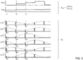
- Fig. 3 shows the timely course of the sense signals q i ( t ), corresponding acquired sense signals q k and determined system states x k
- k of the sensor system 1 of Fig. 1 in the case of six ( r 6) individual sensors HE i generating the sense signals q i ( t ).
- the acquired sense signals q k their digital representations being indicated by solid line boxes below the timely course of the respective sense signals q i ( t ), and the updated system states x k
- k are shown for three state update cycles k 1..3.
- the state update cycles k are represented by their corresponding times t 1 , t 2 , and t 3 .
- the state update cycles k (being equivalent to the prediction cycles k in this case) for each signal channel i are represented by their corresponding times t i,1 ..t i,3 .
- k consisting of the components angle ⁇ k
- k is updated after each complete signal acquisition and prediction cycle using the difference (error signal) y ⁇ k
- k ⁇ 1 q ⁇ k ⁇ q ⁇ ⁇ k
- Fig. 4 shows a functional diagram of another exemplary embodiment of a sensor system 10 for measuring a process value ⁇ ( t )) of a physical system, e.g. the physical system 2 of Fig. 1 , according to the invention.
- the sensor system 10 of Fig. 4 differs from the sensor system 1 shown in Fig. 1 in the following features:
- the sampling period may be chosen by a factor 1/ r smaller, i.e. T ⁇ T / r. In this way the same overall signal rate r / T is maintained as before in the case of the uniform sampling approach used with the sensor system 1 of Fig. 1 .
- Fig. 5 illustrates a functional part of the sensor system 10 of Fig. 4 in more detail.
- the functional part shown in detail in Fig. 5 corresponds to the dashed box in Fig. 4 .
- a pair of cos(n * x), sin(n * x) is a single harmonic of order n, i.e. a full complex harmonic order as the natural space is the complex numbers. Therefore, all harmonics of order equal to 1 or greater than 1 consist of two components (i.e. sine and cosine), and a 0 th order has only one component which is the constant "1".
- two full complex harmonics of order 1 and n, respectively, are used in the prediction operation, wherein - without any limitation thereto - the optional 0 th harmonic (entry "1") is used in this example as well to compensate for a constant offset (e.g. sensor offset).
- a constant offset e.g. sensor offset
- the constant term is not mandatory to be considered at this specific place/operation as it may be possible to subtract a constant offset by other means as well.
- the total number m of the harmonics used i.e. the specific characteristic(s)/components of each harmonic as well as the optional compensation for a constant offset, may be chosen according to specific application requirements.
- the Kalman filter operations provide update formulas for the corrected state x k
- k -1 q i,k - q ⁇ i,k
- Fig. 6 shows the timely course of the sense signals q i ( t ), acquired sense signals q i,k and determined system states x k
- k show the state vector consisting of the components angle ⁇ k
- k is updated at t k after each new sense signal acquisition process using the scalar difference y i,k
- k -1 q i,k - q ⁇ i,k
- Fig. 7 shows the timely course of the sense signals q i ( t ), acquired sense signals q i,k and determined system states x k
- k show the state vector consisting of the components angle ⁇ k
- k is updated each time after a group/set of sense signals q i,k is acquired.
- the groups consist of two sensors each, measured at time instants t i,k , t i +1, k .
- k ⁇ 1 q i , k q i + 1 , k ⁇ q ⁇ i , k
- k ⁇ 1 is used for the state update calculation, i.e.
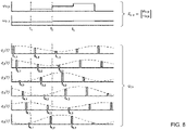
- Fig. 8 shows the timely course of the sense signals q i ( t ), acquired sense signals q i,k and determined system states x k
- k show the state vector consisting of the components phase ⁇ k
- k is updated after each complete sense signal acquisition cycle using the difference y ⁇ k
- k ⁇ 1 q ⁇ k ⁇ q ⁇ ⁇ k
- Fig. 9 shows a flowchart of an exemplary embodiment of method 100 for measuring a process value ⁇ ( t ) of a physical system, such as the physical system 2 in Fig. 1 , according to the invention employed in the sensor system 1 of Fig. 1 .
- the method 100 comprises the steps:
- step 101 is carried out by applying a second operation K to the predicted system state x k
- method 100 will only perform an outer loop 106 because for each state update cycle k there is only one prediction cycle k, i.e. acquisition and prediction of all sense signals in steps 101 and 105 is always performed simultaneously, i.e. at the same single time instant t k .
- method 100 will be employed for operating the sensor system 10 of Fig. 4 , in the second and third operational modes of sensor system 10 shown in Figs. 7 and 8 , the method 100 will also perform an inner loop 107 in which a plurality of sense signals q i,k is acquired and a plurality of correspondingly sense signals q ⁇ i,k
- the system state predictor may additionally use a second order derivative of the process value of the last system state x k -1
Landscapes
- Engineering & Computer Science (AREA)
- Physics & Mathematics (AREA)
- General Physics & Mathematics (AREA)
- Automation & Control Theory (AREA)
- Evolutionary Computation (AREA)
- Artificial Intelligence (AREA)
- Health & Medical Sciences (AREA)
- Computer Vision & Pattern Recognition (AREA)
- Medical Informatics (AREA)
- Software Systems (AREA)
- Mathematical Physics (AREA)
- Technology Law (AREA)
- Indication And Recording Devices For Special Purposes And Tariff Metering Devices (AREA)
- Transmission And Conversion Of Sensor Element Output (AREA)
- Arrangements For Transmission Of Measured Signals (AREA)
Priority Applications (2)
| Application Number | Priority Date | Filing Date | Title |
|---|---|---|---|
| EP20211276.9A EP4009003B1 (fr) | 2020-12-02 | 2020-12-02 | Système de capteur et méthode de mesure d'une valeur de procédé d'un système physique |
| US17/478,564 US11774926B2 (en) | 2020-12-02 | 2021-09-17 | Sensor system and method for measuring a process value of a physical system |
Applications Claiming Priority (1)
| Application Number | Priority Date | Filing Date | Title |
|---|---|---|---|
| EP20211276.9A EP4009003B1 (fr) | 2020-12-02 | 2020-12-02 | Système de capteur et méthode de mesure d'une valeur de procédé d'un système physique |
Publications (2)
| Publication Number | Publication Date |
|---|---|
| EP4009003A1 true EP4009003A1 (fr) | 2022-06-08 |
| EP4009003B1 EP4009003B1 (fr) | 2024-05-29 |
Family
ID=73694866
Family Applications (1)
| Application Number | Title | Priority Date | Filing Date |
|---|---|---|---|
| EP20211276.9A Active EP4009003B1 (fr) | 2020-12-02 | 2020-12-02 | Système de capteur et méthode de mesure d'une valeur de procédé d'un système physique |
Country Status (2)
| Country | Link |
|---|---|
| US (1) | US11774926B2 (fr) |
| EP (1) | EP4009003B1 (fr) |
Citations (5)
| Publication number | Priority date | Publication date | Assignee | Title |
|---|---|---|---|---|
| US6285971B1 (en) * | 1997-08-22 | 2001-09-04 | Voyan Technology | Method for real-time nonlinear system state estimation and control |
| US6662140B2 (en) * | 2001-06-12 | 2003-12-09 | Rolls-Royce Canada Limited | Fuzzy logic estimator for minimizing signal measurement inaccuracy effects in a signal processing system |
| US20060284588A1 (en) * | 2005-06-10 | 2006-12-21 | Societe Nouvelle Wuilfert | Automatic tuning method for the feedback control of a motion simulator, and related device |
| US20120059642A1 (en) * | 2009-03-04 | 2012-03-08 | Ulrich Vollmer | Method and device for the angle sensor-free detection of the position of the rotor shaft of a permanently excited synchronous machine on the basis of current signals and voltage signals |
| US10557722B2 (en) | 2016-09-16 | 2020-02-11 | NM Numerical Modelling GmbH | System for determining the position of the position indicator of a position measuring system |
Family Cites Families (11)
| Publication number | Priority date | Publication date | Assignee | Title |
|---|---|---|---|---|
| US6522130B1 (en) * | 1998-07-20 | 2003-02-18 | Uqm Technologies, Inc. | Accurate rotor position sensor and method using magnet and sensors mounted adjacent to the magnet and motor |
| JP2005339241A (ja) * | 2004-05-27 | 2005-12-08 | Nissan Motor Co Ltd | モデル予測制御装置および車両用推奨操作量生成装置 |
| US8005642B2 (en) * | 2008-06-26 | 2011-08-23 | Infineon Technologies Ag | Predictive angular sensor readout |
| US20120283849A1 (en) * | 2011-05-06 | 2012-11-08 | Kureemun Ridwan | Sensor system having time lag compensation |
| EP2615424B1 (fr) * | 2012-01-13 | 2014-01-08 | SICK STEGMANN GmbH | Procédé pour la supervision d'une fonction correcte d'un capteur modulé périodique de contrôle de la position d'un système de rotation et dispositif de contrôle pour réaliser ce procédé |
| DE102012203909A1 (de) * | 2012-03-13 | 2013-09-19 | Robert Bosch Gmbh | Filterverfahren und Filtervorrichtung für Sensordaten |
| US9436174B2 (en) * | 2013-03-01 | 2016-09-06 | Fisher-Rosemount Systems, Inc. | Kalman filters in process control systems |
| US11402235B2 (en) * | 2017-01-03 | 2022-08-02 | Intel Corporation | Sensor management and reliability |
| DE102017201548A1 (de) * | 2017-01-31 | 2018-08-02 | Siemens Aktiengesellschaft | Verfahren zum Bereitstellen von Messwerten einer technischen Anlage, technisches System und Verfahren zum Betreiben des technischen Systems |
| EP3517897B1 (fr) * | 2018-01-25 | 2020-10-28 | Melexis Technologies SA | Dispositif de détection de position |
| JP7151546B2 (ja) * | 2019-02-25 | 2022-10-12 | オムロン株式会社 | 制御装置、制御方法、及び制御プログラム |
-
2020
- 2020-12-02 EP EP20211276.9A patent/EP4009003B1/fr active Active
-
2021
- 2021-09-17 US US17/478,564 patent/US11774926B2/en active Active
Patent Citations (5)
| Publication number | Priority date | Publication date | Assignee | Title |
|---|---|---|---|---|
| US6285971B1 (en) * | 1997-08-22 | 2001-09-04 | Voyan Technology | Method for real-time nonlinear system state estimation and control |
| US6662140B2 (en) * | 2001-06-12 | 2003-12-09 | Rolls-Royce Canada Limited | Fuzzy logic estimator for minimizing signal measurement inaccuracy effects in a signal processing system |
| US20060284588A1 (en) * | 2005-06-10 | 2006-12-21 | Societe Nouvelle Wuilfert | Automatic tuning method for the feedback control of a motion simulator, and related device |
| US20120059642A1 (en) * | 2009-03-04 | 2012-03-08 | Ulrich Vollmer | Method and device for the angle sensor-free detection of the position of the rotor shaft of a permanently excited synchronous machine on the basis of current signals and voltage signals |
| US10557722B2 (en) | 2016-09-16 | 2020-02-11 | NM Numerical Modelling GmbH | System for determining the position of the position indicator of a position measuring system |
Also Published As
| Publication number | Publication date |
|---|---|
| US11774926B2 (en) | 2023-10-03 |
| EP4009003B1 (fr) | 2024-05-29 |
| US20220171352A1 (en) | 2022-06-02 |
Similar Documents
| Publication | Publication Date | Title |
|---|---|---|
| US9857782B2 (en) | Output value correction method for physical quantity sensor apparatus, output correction method for physical quantity sensor, physical quantity sensor apparatus and output value correction apparatus for physical quantity sensor | |
| US8005642B2 (en) | Predictive angular sensor readout | |
| GB1575148A (en) | Electrical energy meters | |
| US20090034641A1 (en) | System and method for dynamic calibration of a quadrature encoder | |
| JP4111813B2 (ja) | 磁気センサ信号処理集積回路、その回転角度測定方法および回転角度センサ | |
| CN113324565A (zh) | 机械角度检测方法、云台及机器可读存储介质 | |
| JPH0141923B2 (fr) | ||
| JP7165149B2 (ja) | 磁場の絶対角度を判断する方法、デジタル信号プロセッサーおよびシステム | |
| EP4009003B1 (fr) | Système de capteur et méthode de mesure d'une valeur de procédé d'un système physique | |
| CN112087232B (zh) | 一种tiadc系统直流偏置和增益误差校准方法及装置 | |
| WO2024113450A1 (fr) | Procédé et appareil de correction de codeur magnétique, et codeur magnétique | |
| JP2007155668A (ja) | 回転角度センサ、および、回転角度検出方法 | |
| US20030033103A1 (en) | Position detection data generating method and apparatus based on phase shift principle | |
| CN107747946B (zh) | 一种星敏间轨道周期系统误差在线辨识补偿方法 | |
| JP2008180547A (ja) | 内挿誤差補正装置 | |
| CN117574635A (zh) | 一种多圈转位机构角度解算方法 | |
| CN111207723B (zh) | 一种差分式圆感应同步器的解调方法 | |
| CN115208259A (zh) | 一种永磁同步电机测速方法 | |
| USH104H (en) | Digital resolver compensation technique | |
| US10866079B2 (en) | Position sensing device | |
| Babalola et al. | Real-time measurement of frequency using affordable rotary encoder and LabVIEW | |
| JP4518871B2 (ja) | 内挿誤差補正方法及び装置 | |
| EP2767805B1 (fr) | Procédé de correction de dérive de phase d'un codeur de position capacitif et codeur de position capacitif | |
| US5128883A (en) | Method for absolute position determination of multi-speed devices | |
| JPH10148648A (ja) | 電気計器 |
Legal Events
| Date | Code | Title | Description |
|---|---|---|---|
| PUAI | Public reference made under article 153(3) epc to a published international application that has entered the european phase |
Free format text: ORIGINAL CODE: 0009012 |
|
| STAA | Information on the status of an ep patent application or granted ep patent |
Free format text: STATUS: THE APPLICATION HAS BEEN PUBLISHED |
|
| AK | Designated contracting states |
Kind code of ref document: A1 Designated state(s): AL AT BE BG CH CY CZ DE DK EE ES FI FR GB GR HR HU IE IS IT LI LT LU LV MC MK MT NL NO PL PT RO RS SE SI SK SM TR |
|
| STAA | Information on the status of an ep patent application or granted ep patent |
Free format text: STATUS: REQUEST FOR EXAMINATION WAS MADE |
|
| 17P | Request for examination filed |
Effective date: 20221207 |
|
| RBV | Designated contracting states (corrected) |
Designated state(s): AL AT BE BG CH CY CZ DE DK EE ES FI FR GB GR HR HU IE IS IT LI LT LU LV MC MK MT NL NO PL PT RO RS SE SI SK SM TR |
|
| RAP3 | Party data changed (applicant data changed or rights of an application transferred) |
Owner name: MAGLAB AG Owner name: NM NUMERICAL MODELLING GMBH |
|
| GRAP | Despatch of communication of intention to grant a patent |
Free format text: ORIGINAL CODE: EPIDOSNIGR1 |
|
| STAA | Information on the status of an ep patent application or granted ep patent |
Free format text: STATUS: GRANT OF PATENT IS INTENDED |
|
| INTG | Intention to grant announced |
Effective date: 20231207 |
|
| RAP3 | Party data changed (applicant data changed or rights of an application transferred) |
Owner name: MAGLAB AG Owner name: NM NUMERICAL MODELLING GMBH |
|
| GRAS | Grant fee paid |
Free format text: ORIGINAL CODE: EPIDOSNIGR3 |
|
| GRAA | (expected) grant |
Free format text: ORIGINAL CODE: 0009210 |
|
| STAA | Information on the status of an ep patent application or granted ep patent |
Free format text: STATUS: THE PATENT HAS BEEN GRANTED |
|
| AK | Designated contracting states |
Kind code of ref document: B1 Designated state(s): AL AT BE BG CH CY CZ DE DK EE ES FI FR GB GR HR HU IE IS IT LI LT LU LV MC MK MT NL NO PL PT RO RS SE SI SK SM TR |
|
| REG | Reference to a national code |
Ref country code: CH Ref legal event code: EP |
|
| REG | Reference to a national code |
Ref country code: IE Ref legal event code: FG4D |
|
| REG | Reference to a national code |
Ref country code: DE Ref legal event code: R096 Ref document number: 602020031585 Country of ref document: DE |
|
| P01 | Opt-out of the competence of the unified patent court (upc) registered |
Free format text: CASE NUMBER: APP_33244/2024 Effective date: 20240604 |
|
| REG | Reference to a national code |
Ref country code: LT Ref legal event code: MG9D |
|
| REG | Reference to a national code |
Ref country code: NL Ref legal event code: MP Effective date: 20240529 |
|
| PG25 | Lapsed in a contracting state [announced via postgrant information from national office to epo] |
Ref country code: IS Free format text: LAPSE BECAUSE OF FAILURE TO SUBMIT A TRANSLATION OF THE DESCRIPTION OR TO PAY THE FEE WITHIN THE PRESCRIBED TIME-LIMIT Effective date: 20240929 |
|
| PG25 | Lapsed in a contracting state [announced via postgrant information from national office to epo] |
Ref country code: BG Free format text: LAPSE BECAUSE OF FAILURE TO SUBMIT A TRANSLATION OF THE DESCRIPTION OR TO PAY THE FEE WITHIN THE PRESCRIBED TIME-LIMIT Effective date: 20240529 |
|
| PG25 | Lapsed in a contracting state [announced via postgrant information from national office to epo] |
Ref country code: FI Free format text: LAPSE BECAUSE OF FAILURE TO SUBMIT A TRANSLATION OF THE DESCRIPTION OR TO PAY THE FEE WITHIN THE PRESCRIBED TIME-LIMIT Effective date: 20240529 Ref country code: HR Free format text: LAPSE BECAUSE OF FAILURE TO SUBMIT A TRANSLATION OF THE DESCRIPTION OR TO PAY THE FEE WITHIN THE PRESCRIBED TIME-LIMIT Effective date: 20240529 |
|
| PG25 | Lapsed in a contracting state [announced via postgrant information from national office to epo] |
Ref country code: GR Free format text: LAPSE BECAUSE OF FAILURE TO SUBMIT A TRANSLATION OF THE DESCRIPTION OR TO PAY THE FEE WITHIN THE PRESCRIBED TIME-LIMIT Effective date: 20240830 |
|
| REG | Reference to a national code |
Ref country code: AT Ref legal event code: MK05 Ref document number: 1690999 Country of ref document: AT Kind code of ref document: T Effective date: 20240529 |
|
| PG25 | Lapsed in a contracting state [announced via postgrant information from national office to epo] |
Ref country code: ES Free format text: LAPSE BECAUSE OF FAILURE TO SUBMIT A TRANSLATION OF THE DESCRIPTION OR TO PAY THE FEE WITHIN THE PRESCRIBED TIME-LIMIT Effective date: 20240529 |
|
| PG25 | Lapsed in a contracting state [announced via postgrant information from national office to epo] |
Ref country code: AT Free format text: LAPSE BECAUSE OF FAILURE TO SUBMIT A TRANSLATION OF THE DESCRIPTION OR TO PAY THE FEE WITHIN THE PRESCRIBED TIME-LIMIT Effective date: 20240529 |
|
| PG25 | Lapsed in a contracting state [announced via postgrant information from national office to epo] |
Ref country code: PL Free format text: LAPSE BECAUSE OF FAILURE TO SUBMIT A TRANSLATION OF THE DESCRIPTION OR TO PAY THE FEE WITHIN THE PRESCRIBED TIME-LIMIT Effective date: 20240529 |
|
| PG25 | Lapsed in a contracting state [announced via postgrant information from national office to epo] |
Ref country code: LV Free format text: LAPSE BECAUSE OF FAILURE TO SUBMIT A TRANSLATION OF THE DESCRIPTION OR TO PAY THE FEE WITHIN THE PRESCRIBED TIME-LIMIT Effective date: 20240529 |
|
| PG25 | Lapsed in a contracting state [announced via postgrant information from national office to epo] |
Ref country code: PL Free format text: LAPSE BECAUSE OF FAILURE TO SUBMIT A TRANSLATION OF THE DESCRIPTION OR TO PAY THE FEE WITHIN THE PRESCRIBED TIME-LIMIT Effective date: 20240529 Ref country code: NO Free format text: LAPSE BECAUSE OF FAILURE TO SUBMIT A TRANSLATION OF THE DESCRIPTION OR TO PAY THE FEE WITHIN THE PRESCRIBED TIME-LIMIT Effective date: 20240829 Ref country code: LV Free format text: LAPSE BECAUSE OF FAILURE TO SUBMIT A TRANSLATION OF THE DESCRIPTION OR TO PAY THE FEE WITHIN THE PRESCRIBED TIME-LIMIT Effective date: 20240529 Ref country code: IS Free format text: LAPSE BECAUSE OF FAILURE TO SUBMIT A TRANSLATION OF THE DESCRIPTION OR TO PAY THE FEE WITHIN THE PRESCRIBED TIME-LIMIT Effective date: 20240929 Ref country code: HR Free format text: LAPSE BECAUSE OF FAILURE TO SUBMIT A TRANSLATION OF THE DESCRIPTION OR TO PAY THE FEE WITHIN THE PRESCRIBED TIME-LIMIT Effective date: 20240529 Ref country code: GR Free format text: LAPSE BECAUSE OF FAILURE TO SUBMIT A TRANSLATION OF THE DESCRIPTION OR TO PAY THE FEE WITHIN THE PRESCRIBED TIME-LIMIT Effective date: 20240830 Ref country code: FI Free format text: LAPSE BECAUSE OF FAILURE TO SUBMIT A TRANSLATION OF THE DESCRIPTION OR TO PAY THE FEE WITHIN THE PRESCRIBED TIME-LIMIT Effective date: 20240529 Ref country code: ES Free format text: LAPSE BECAUSE OF FAILURE TO SUBMIT A TRANSLATION OF THE DESCRIPTION OR TO PAY THE FEE WITHIN THE PRESCRIBED TIME-LIMIT Effective date: 20240529 Ref country code: BG Free format text: LAPSE BECAUSE OF FAILURE TO SUBMIT A TRANSLATION OF THE DESCRIPTION OR TO PAY THE FEE WITHIN THE PRESCRIBED TIME-LIMIT Effective date: 20240529 Ref country code: AT Free format text: LAPSE BECAUSE OF FAILURE TO SUBMIT A TRANSLATION OF THE DESCRIPTION OR TO PAY THE FEE WITHIN THE PRESCRIBED TIME-LIMIT Effective date: 20240529 Ref country code: RS Free format text: LAPSE BECAUSE OF FAILURE TO SUBMIT A TRANSLATION OF THE DESCRIPTION OR TO PAY THE FEE WITHIN THE PRESCRIBED TIME-LIMIT Effective date: 20240829 |
|
| PG25 | Lapsed in a contracting state [announced via postgrant information from national office to epo] |
Ref country code: NL Free format text: LAPSE BECAUSE OF FAILURE TO SUBMIT A TRANSLATION OF THE DESCRIPTION OR TO PAY THE FEE WITHIN THE PRESCRIBED TIME-LIMIT Effective date: 20240529 |
|
| PG25 | Lapsed in a contracting state [announced via postgrant information from national office to epo] |
Ref country code: NL Free format text: LAPSE BECAUSE OF FAILURE TO SUBMIT A TRANSLATION OF THE DESCRIPTION OR TO PAY THE FEE WITHIN THE PRESCRIBED TIME-LIMIT Effective date: 20240529 |
|
| PG25 | Lapsed in a contracting state [announced via postgrant information from national office to epo] |
Ref country code: DK Free format text: LAPSE BECAUSE OF FAILURE TO SUBMIT A TRANSLATION OF THE DESCRIPTION OR TO PAY THE FEE WITHIN THE PRESCRIBED TIME-LIMIT Effective date: 20240529 |
|
| PG25 | Lapsed in a contracting state [announced via postgrant information from national office to epo] |
Ref country code: EE Free format text: LAPSE BECAUSE OF FAILURE TO SUBMIT A TRANSLATION OF THE DESCRIPTION OR TO PAY THE FEE WITHIN THE PRESCRIBED TIME-LIMIT Effective date: 20240529 |
|
| PG25 | Lapsed in a contracting state [announced via postgrant information from national office to epo] |
Ref country code: CZ Free format text: LAPSE BECAUSE OF FAILURE TO SUBMIT A TRANSLATION OF THE DESCRIPTION OR TO PAY THE FEE WITHIN THE PRESCRIBED TIME-LIMIT Effective date: 20240529 |
|
| PG25 | Lapsed in a contracting state [announced via postgrant information from national office to epo] |
Ref country code: SK Free format text: LAPSE BECAUSE OF FAILURE TO SUBMIT A TRANSLATION OF THE DESCRIPTION OR TO PAY THE FEE WITHIN THE PRESCRIBED TIME-LIMIT Effective date: 20240529 Ref country code: RO Free format text: LAPSE BECAUSE OF FAILURE TO SUBMIT A TRANSLATION OF THE DESCRIPTION OR TO PAY THE FEE WITHIN THE PRESCRIBED TIME-LIMIT Effective date: 20240529 |
|
| PG25 | Lapsed in a contracting state [announced via postgrant information from national office to epo] |
Ref country code: SM Free format text: LAPSE BECAUSE OF FAILURE TO SUBMIT A TRANSLATION OF THE DESCRIPTION OR TO PAY THE FEE WITHIN THE PRESCRIBED TIME-LIMIT Effective date: 20240529 |
|
| PG25 | Lapsed in a contracting state [announced via postgrant information from national office to epo] |
Ref country code: SM Free format text: LAPSE BECAUSE OF FAILURE TO SUBMIT A TRANSLATION OF THE DESCRIPTION OR TO PAY THE FEE WITHIN THE PRESCRIBED TIME-LIMIT Effective date: 20240529 Ref country code: SK Free format text: LAPSE BECAUSE OF FAILURE TO SUBMIT A TRANSLATION OF THE DESCRIPTION OR TO PAY THE FEE WITHIN THE PRESCRIBED TIME-LIMIT Effective date: 20240529 Ref country code: RO Free format text: LAPSE BECAUSE OF FAILURE TO SUBMIT A TRANSLATION OF THE DESCRIPTION OR TO PAY THE FEE WITHIN THE PRESCRIBED TIME-LIMIT Effective date: 20240529 Ref country code: EE Free format text: LAPSE BECAUSE OF FAILURE TO SUBMIT A TRANSLATION OF THE DESCRIPTION OR TO PAY THE FEE WITHIN THE PRESCRIBED TIME-LIMIT Effective date: 20240529 Ref country code: DK Free format text: LAPSE BECAUSE OF FAILURE TO SUBMIT A TRANSLATION OF THE DESCRIPTION OR TO PAY THE FEE WITHIN THE PRESCRIBED TIME-LIMIT Effective date: 20240529 Ref country code: CZ Free format text: LAPSE BECAUSE OF FAILURE TO SUBMIT A TRANSLATION OF THE DESCRIPTION OR TO PAY THE FEE WITHIN THE PRESCRIBED TIME-LIMIT Effective date: 20240529 |
|
| PG25 | Lapsed in a contracting state [announced via postgrant information from national office to epo] |
Ref country code: IT Free format text: LAPSE BECAUSE OF FAILURE TO SUBMIT A TRANSLATION OF THE DESCRIPTION OR TO PAY THE FEE WITHIN THE PRESCRIBED TIME-LIMIT Effective date: 20240529 |
|
| REG | Reference to a national code |
Ref country code: DE Ref legal event code: R097 Ref document number: 602020031585 Country of ref document: DE |
|
| PLBE | No opposition filed within time limit |
Free format text: ORIGINAL CODE: 0009261 |
|
| STAA | Information on the status of an ep patent application or granted ep patent |
Free format text: STATUS: NO OPPOSITION FILED WITHIN TIME LIMIT |
|
| PG25 | Lapsed in a contracting state [announced via postgrant information from national office to epo] |
Ref country code: SI Free format text: LAPSE BECAUSE OF FAILURE TO SUBMIT A TRANSLATION OF THE DESCRIPTION OR TO PAY THE FEE WITHIN THE PRESCRIBED TIME-LIMIT Effective date: 20240529 |
|
| 26N | No opposition filed |
Effective date: 20250303 |
|
| PG25 | Lapsed in a contracting state [announced via postgrant information from national office to epo] |
Ref country code: MC Free format text: LAPSE BECAUSE OF FAILURE TO SUBMIT A TRANSLATION OF THE DESCRIPTION OR TO PAY THE FEE WITHIN THE PRESCRIBED TIME-LIMIT Effective date: 20240529 |
|
| REG | Reference to a national code |
Ref country code: CH Ref legal event code: PL |
|
| PG25 | Lapsed in a contracting state [announced via postgrant information from national office to epo] |
Ref country code: LU Free format text: LAPSE BECAUSE OF NON-PAYMENT OF DUE FEES Effective date: 20241202 |
|
| PG25 | Lapsed in a contracting state [announced via postgrant information from national office to epo] |
Ref country code: SE Free format text: LAPSE BECAUSE OF FAILURE TO SUBMIT A TRANSLATION OF THE DESCRIPTION OR TO PAY THE FEE WITHIN THE PRESCRIBED TIME-LIMIT Effective date: 20240529 |
|
| REG | Reference to a national code |
Ref country code: BE Ref legal event code: MM Effective date: 20241231 |
|
| PG25 | Lapsed in a contracting state [announced via postgrant information from national office to epo] |
Ref country code: BE Free format text: LAPSE BECAUSE OF NON-PAYMENT OF DUE FEES Effective date: 20241231 |
|
| PG25 | Lapsed in a contracting state [announced via postgrant information from national office to epo] |
Ref country code: CH Free format text: LAPSE BECAUSE OF NON-PAYMENT OF DUE FEES Effective date: 20241231 |
|
| PG25 | Lapsed in a contracting state [announced via postgrant information from national office to epo] |
Ref country code: IE Free format text: LAPSE BECAUSE OF NON-PAYMENT OF DUE FEES Effective date: 20241202 |
|
| PGFP | Annual fee paid to national office [announced via postgrant information from national office to epo] |
Ref country code: GB Payment date: 20251229 Year of fee payment: 6 |
|
| PGFP | Annual fee paid to national office [announced via postgrant information from national office to epo] |
Ref country code: FR Payment date: 20251226 Year of fee payment: 6 |
|
| PG25 | Lapsed in a contracting state [announced via postgrant information from national office to epo] |
Ref country code: PT Free format text: LAPSE BECAUSE OF NON-PAYMENT OF DUE FEES Effective date: 20240529 |
|
| PG25 | Lapsed in a contracting state [announced via postgrant information from national office to epo] |
Ref country code: CY Free format text: LAPSE BECAUSE OF FAILURE TO SUBMIT A TRANSLATION OF THE DESCRIPTION OR TO PAY THE FEE WITHIN THE PRESCRIBED TIME-LIMIT; INVALID AB INITIO Effective date: 20201202 |
|
| PGFP | Annual fee paid to national office [announced via postgrant information from national office to epo] |
Ref country code: DE Payment date: 20251229 Year of fee payment: 6 |