EP4009125B1 - Procede de determination d'informations concernant une condition d'un systeme de moteur d'entrainement et/ou d'un pack d'accumulateur d'entrainement d'une machine de jardinage, de foresterie et/ou de construction et d'un systeme pour determiner des informations sur l'etat d'un systeme de moteur d'entrainement et/ou de traitement de construction de systeme de moteur d'entrainement équipement - Google Patents
Procede de determination d'informations concernant une condition d'un systeme de moteur d'entrainement et/ou d'un pack d'accumulateur d'entrainement d'une machine de jardinage, de foresterie et/ou de construction et d'un systeme pour determiner des informations sur l'etat d'un systeme de moteur d'entrainement et/ou de traitement de construction de systeme de moteur d'entrainement équipement Download PDFInfo
- Publication number
- EP4009125B1 EP4009125B1 EP20211296.7A EP20211296A EP4009125B1 EP 4009125 B1 EP4009125 B1 EP 4009125B1 EP 20211296 A EP20211296 A EP 20211296A EP 4009125 B1 EP4009125 B1 EP 4009125B1
- Authority
- EP
- European Patent Office
- Prior art keywords
- temperature
- drive motor
- model
- motor system
- drive
- Prior art date
- Legal status (The legal status is an assumption and is not a legal conclusion. Google has not performed a legal analysis and makes no representation as to the accuracy of the status listed.)
- Active
Links
Images
Classifications
-
- H—ELECTRICITY
- H02—GENERATION; CONVERSION OR DISTRIBUTION OF ELECTRIC POWER
- H02K—DYNAMO-ELECTRIC MACHINES
- H02K11/00—Structural association of dynamo-electric machines with electric components or with devices for shielding, monitoring or protection
- H02K11/20—Structural association of dynamo-electric machines with electric components or with devices for shielding, monitoring or protection for measuring, monitoring, testing, protecting or switching
- H02K11/25—Devices for sensing temperature, or actuated thereby
-
- G—PHYSICS
- G05—CONTROLLING; REGULATING
- G05B—CONTROL OR REGULATING SYSTEMS IN GENERAL; FUNCTIONAL ELEMENTS OF SUCH SYSTEMS; MONITORING OR TESTING ARRANGEMENTS FOR SUCH SYSTEMS OR ELEMENTS
- G05B23/00—Testing or monitoring of control systems or parts thereof
- G05B23/02—Electric testing or monitoring
- G05B23/0205—Electric testing or monitoring by means of a monitoring system capable of detecting and responding to faults
- G05B23/0259—Electric testing or monitoring by means of a monitoring system capable of detecting and responding to faults characterized by the response to fault detection
- G05B23/0283—Predictive maintenance, e.g. involving the monitoring of a system and, based on the monitoring results, taking decisions on the maintenance schedule of the monitored system; Estimating remaining useful life [RUL]
-
- F—MECHANICAL ENGINEERING; LIGHTING; HEATING; WEAPONS; BLASTING
- F02—COMBUSTION ENGINES; HOT-GAS OR COMBUSTION-PRODUCT ENGINE PLANTS
- F02D—CONTROLLING COMBUSTION ENGINES
- F02D41/00—Electrical control of supply of combustible mixture or its constituents
- F02D41/02—Circuit arrangements for generating control signals
- F02D41/04—Introducing corrections for particular operating conditions
- F02D41/042—Introducing corrections for particular operating conditions for stopping the engine
-
- A—HUMAN NECESSITIES
- A01—AGRICULTURE; FORESTRY; ANIMAL HUSBANDRY; HUNTING; TRAPPING; FISHING
- A01D—HARVESTING; MOWING
- A01D69/00—Driving mechanisms or parts thereof for harvesters or mowers
- A01D69/002—Driving mechanisms or parts thereof for harvesters or mowers driven by power take-off
-
- A—HUMAN NECESSITIES
- A01—AGRICULTURE; FORESTRY; ANIMAL HUSBANDRY; HUNTING; TRAPPING; FISHING
- A01D—HARVESTING; MOWING
- A01D69/00—Driving mechanisms or parts thereof for harvesters or mowers
- A01D69/02—Driving mechanisms or parts thereof for harvesters or mowers electric
-
- A—HUMAN NECESSITIES
- A01—AGRICULTURE; FORESTRY; ANIMAL HUSBANDRY; HUNTING; TRAPPING; FISHING
- A01G—HORTICULTURE; CULTIVATION OF VEGETABLES, FLOWERS, RICE, FRUIT, VINES, HOPS OR SEAWEED; FORESTRY; WATERING
- A01G3/00—Cutting implements specially adapted for horticultural purposes; Delimbing standing trees
- A01G3/08—Other tools for pruning, branching or delimbing standing trees
- A01G3/085—Motor-driven saws for pruning or branching
- A01G3/086—Chain saws
-
- F—MECHANICAL ENGINEERING; LIGHTING; HEATING; WEAPONS; BLASTING
- F02—COMBUSTION ENGINES; HOT-GAS OR COMBUSTION-PRODUCT ENGINE PLANTS
- F02B—INTERNAL-COMBUSTION PISTON ENGINES; COMBUSTION ENGINES IN GENERAL
- F02B63/00—Adaptations of engines for driving pumps, hand-held tools or electric generators; Portable combinations of engines with engine-driven devices
- F02B63/02—Adaptations of engines for driving pumps, hand-held tools or electric generators; Portable combinations of engines with engine-driven devices for hand-held tools
-
- F—MECHANICAL ENGINEERING; LIGHTING; HEATING; WEAPONS; BLASTING
- F02—COMBUSTION ENGINES; HOT-GAS OR COMBUSTION-PRODUCT ENGINE PLANTS
- F02D—CONTROLLING COMBUSTION ENGINES
- F02D29/00—Controlling engines, such controlling being peculiar to the devices driven thereby, the devices being other than parts or accessories essential to engine operation, e.g. controlling of engines by signals external thereto
-
- G—PHYSICS
- G01—MEASURING; TESTING
- G01K—MEASURING TEMPERATURE; MEASURING QUANTITY OF HEAT; THERMALLY-SENSITIVE ELEMENTS NOT OTHERWISE PROVIDED FOR
- G01K13/00—Thermometers specially adapted for specific purposes
-
- G—PHYSICS
- G05—CONTROLLING; REGULATING
- G05B—CONTROL OR REGULATING SYSTEMS IN GENERAL; FUNCTIONAL ELEMENTS OF SUCH SYSTEMS; MONITORING OR TESTING ARRANGEMENTS FOR SUCH SYSTEMS OR ELEMENTS
- G05B23/00—Testing or monitoring of control systems or parts thereof
- G05B23/02—Electric testing or monitoring
- G05B23/0205—Electric testing or monitoring by means of a monitoring system capable of detecting and responding to faults
- G05B23/0218—Electric testing or monitoring by means of a monitoring system capable of detecting and responding to faults characterised by the fault detection method dealing with either existing or incipient faults
- G05B23/0243—Electric testing or monitoring by means of a monitoring system capable of detecting and responding to faults characterised by the fault detection method dealing with either existing or incipient faults model based detection method, e.g. first-principles knowledge model
- G05B23/0254—Electric testing or monitoring by means of a monitoring system capable of detecting and responding to faults characterised by the fault detection method dealing with either existing or incipient faults model based detection method, e.g. first-principles knowledge model based on a quantitative model, e.g. mathematical relationships between inputs and outputs; functions: observer, Kalman filter, residual calculation, Neural Networks
-
- G—PHYSICS
- G05—CONTROLLING; REGULATING
- G05B—CONTROL OR REGULATING SYSTEMS IN GENERAL; FUNCTIONAL ELEMENTS OF SUCH SYSTEMS; MONITORING OR TESTING ARRANGEMENTS FOR SUCH SYSTEMS OR ELEMENTS
- G05B23/00—Testing or monitoring of control systems or parts thereof
- G05B23/02—Electric testing or monitoring
- G05B23/0205—Electric testing or monitoring by means of a monitoring system capable of detecting and responding to faults
- G05B23/0259—Electric testing or monitoring by means of a monitoring system capable of detecting and responding to faults characterized by the response to fault detection
- G05B23/0286—Modifications to the monitored process, e.g. stopping operation or adapting control
-
- F—MECHANICAL ENGINEERING; LIGHTING; HEATING; WEAPONS; BLASTING
- F02—COMBUSTION ENGINES; HOT-GAS OR COMBUSTION-PRODUCT ENGINE PLANTS
- F02D—CONTROLLING COMBUSTION ENGINES
- F02D2400/00—Control systems adapted for specific engine types; Special features of engine control systems not otherwise provided for; Power supply, connectors or cabling for engine control systems
- F02D2400/06—Small engines with electronic control, e.g. for hand held tools
Definitions
- the invention relates to a method for determining information about a state of a drive motor system and/or a drive accumulator pack of a gardening, forestry and/or construction device and a system for determining information about a state of a drive motor system and/or a drive accumulator pack of a gardening, forestry and/or construction device.
- the US 2019/0010880 A1 discloses a method for determining information for adjusting an adjustable component of an internal combustion engine drive system of a gardening and/or forestry device.
- the method comprises the steps of: providing a characteristic parameter by means of a mobile provision device, wherein the characteristic parameter describes a characteristic of an environment of the gardening and/or forestry device; and determining the information for adjusting the adjustable component depending on the characteristic parameter provided.
- the DE 10 2009 054 400 A1 and US2019/156226 disclose an evaluation device, a system and a method for checking a device of a motor vehicle.
- the US2020/263622 reveals the prediction of equipment maintenance involves the comparison between a temperature result from a model and the distribution of the actual measured temperature.
- the invention is based on the object of providing a method for determining information about a state of a drive motor system and/or a drive accumulator pack of a gardening, forestry and/or construction device and a system for determining information about a state of a drive motor system and/or a drive accumulator pack of a gardening, forestry and/or construction device, wherein the method and the system each have improved properties, in particular more functionalities.
- the inventive, in particular automatic, method is designed, configured or provided for, in particular automatically, determining information, in particular a value of the information, about a, in particular assumed and/or actual, state, in particular a value of the state, of a drive motor system and/or a drive accumulator pack of a gardening, forestry and/or construction processing device.
- the method comprises or has the steps: detecting, in particular automatically and/or immediately or directly detecting, at least one sensor temperature, in particular a value of the sensor temperature, at least one temperature component of the drive motor system and/or the drive accumulator pack by means of at least one, in particular electrical, component temperature sensor, in particular of the drive motor system and/or the drive accumulator pack and/or the gardening, forestry and/or construction equipment, simultaneously with and/or after operation of the drive motor system and/or the drive accumulator pack, in particular the temperature component, in particular and a heater and/or a cooler and/or a fan for heating and/or cooling the drive accumulator pack.
- the temperature component heats up or cools down due to the operation or as a result of the operation.
- the sensor temperature increases or decreases due to the operation.
- the operating data are different from the sensor temperature. Comparing, in particular automatically comparing, the recorded sensor temperature or a variable based on the sensor temperature, in particular recorded, in particular a value of the variable, and the determined operating data or a variable based on the operating data, in particular recorded, in particular a value of the variable, by means of a temperature model.
- the temperature model is based on at least one model or assumed state of the drive motor system and/or the drive accumulator pack, in particular on a description of the model state. Determining, in particular automatically determining, the information depending on a result of the comparison.
- the state is, for example, a contamination, maintenance and/or defect state.
- the method enables the information, in particular the state, to be determined indirectly. In other words: the information, in particular the state, does not need to or cannot be determined, in particular recorded, immediately or directly. Additionally or alternatively, the method enables the information, in particular the state, to be determined using few and/or already existing means. This therefore enables the information, in particular the state, to be determined cost-effectively.
- the method may include or comprise: determining the state depending on the result of the comparison.
- the method may include or comprise: determining the information depending on the determined state.
- the condition can be intended or proper or not intended or proper.
- the gardening, forestry and/or construction equipment can be a ground-guided and/or hand-guided, in particular hand-carried, gardening, forestry and/or construction equipment.
- hand-guided, in particular hand-carried, gardening, forestry and/or construction equipment can mean that the gardening, forestry and/or construction equipment can have a mass of a maximum of 50 kilograms (kg), in particular a maximum of 20 kg, in particular a maximum of 10 kg, in particular a maximum of 5 kg, and/or a minimum of 1 kg, in particular a minimum of 2 kg.
- the gardening, forestry and/or construction equipment can be a saw, in particular a chainsaw, or a pole pruner or a brush cutter or a blower or a cut-off grinder or a lawn mower, in particular a robotic lawn mower.
- the component temperature sensor can thermally contact the temperature component, in particular touch it.
- the operation can be a motor operation, in particular of the drive motor system. Additionally or alternatively, the operation can be a discharging and/or charging and/or heating and/or cooling operation of the drive accumulator pack.
- a charging device in particular an electric one, for charging the drive accumulator pack can have or include the heater and/or the cooler and/or the fan.
- the cooling can be carried out or take place only or purely by means of the fan.
- the heating can be carried out or take place by means of the heater and/or a charging and/or pack current and the fan.
- the drive motor system and/or the drive battery pack in particular each, can generate heat during, in particular during, operation.
- the recording of the sensor temperature after operation can be carried out until a maximum time limit, e.g. two hours (h), after operation has been reached, in particular, and no longer after that.
- a maximum time limit e.g. two hours (h)
- the operating data can include, in particular be, operating data of the drive motor system and/or the drive accumulator pack, in particular the temperature component, and/or the heater and/or the cooler and/or the fan, in particular the charger.
- the method can include or comprise: recording the operating data by means of at least one, in particular electrical, operating data sensor, in particular of the drive motor system and/or the drive accumulator pack and/or the gardening, forestry and/or construction equipment and/or the heater and/or the cooler and/or the fan, in particular the charger.
- the operating data do not need to or can include, in particular be, the sensor temperature, in particular a temperature.
- the temperature model may be a temperature evolution and/or time course model. Additionally or alternatively, the temperature model may be based on a determined or proper model state and/or a non-determined or proper model state.
- the determination of the information can be carried out after the comparison using the temperature model. Additionally or alternatively, the comparison using the temperature model can be carried out after the sensor temperature has been detected and/or the operating data has been determined. Additionally or alternatively, the operating data can be determined before, at the same time as and/or after the sensor temperature has been detected. Additionally or alternatively, the sensor temperature and/or the operating data can be detected, in particular multiple times, repeatedly or permanently or continuously. Additionally or alternatively, the variable based on the sensor temperature and/or the variable based on the operating data can be, in particular in each case, a temporal The method can be a course or a temporal gradient or a temporal derivative, in particular made possible by repeated execution. In addition or alternatively, the method can be repeated, in particular multiple times, or carried out permanently or continuously.
- the operating data are related to an energy supply, in particular a value of the energy supply, the operation, in particular to the operation, and/or a heat dissipation, in particular a value of the heat dissipation and/or a target heat dissipation, due to the operation or through the operation, in particular as intended or proper.
- the operating data include or have an operating runtime, in particular a value of the operating runtime, and/or an operating current, in particular a value of the operating current and/or a motor current and/or a pack current, and/or an operating voltage, in particular a value of the operating voltage and/or a motor voltage and/or a pack voltage, and/or a speed, in particular a value of the speed and/or an engine speed, and/or an injection ratio, in particular a value of the injection ratio, and/or an injection quantity, in particular a value of the injection quantity, and/or a fuel quantity, in particular a value of the fuel quantity.
- an operating runtime in particular a value of the operating runtime
- an operating current in particular a value of the operating current and/or a motor current and/or a pack current
- an operating voltage in particular a value of the operating voltage and/or a motor voltage and/or a pack voltage
- a speed in particular a value of the speed and/or an engine speed
- an injection ratio
- the energy supply enables, in particular the operating time, the operating current, the operating voltage, the speed, the injection ratio, the injection quantity and/or the fuel quantity, that the temperature component can heat up due to operation, and/or that the temperature model can be based on Joule heat, in particular generated by the operating current and/or switching losses, in particular generated by the operating current and the operating voltage, and/or frictional heat, in particular generated by the speed.
- the heat dissipation in particular the speed, enables cooling of the temperature component and thus that the temperature component cannot heat up so quickly and/or only to an equilibrium temperature value, and/or that the temperature model can be based on ventilation cooling.
- the drive motor system can be an electric drive motor system or an internal combustion drive motor system.
- the temperature component is an electric drive motor or a combustion drive motor or a motor electronics, in particular a motor power electronics, or a battery cell or a pack electronics, in particular a Pack power electronics.
- the sensor temperature can be a cylinder head temperature.
- the method comprises or comprises: determining, in particular automatically determining and/or calculating, at least one model temperature, in particular a value of the model temperature, or a variable representative of the model temperature, in particular based on the model temperature, in particular a value of the variable, of the at least one temperature component based on the determined operating data by means of the temperature model, in particular repeatedly, in particular repeatedly several times. Comparing, in particular automatically comparing, the detected sensor temperature or the variable based on the sensor temperature with the determined model temperature or the determined variable representative of the model temperature, in particular repeatedly, in particular repeatedly several times.
- the temperature model can be based on Joule heat and/or frictional heat and/or convection, in particular convection cooling, and/or ventilation cooling.
- the method in particular the comparison, comprises: determining, in particular automatically determining and/or calculating, a deviation, in particular a value of the deviation and/or a difference, of the detected sensor temperature or the variable based on the sensor temperature from the determined model temperature or the variable representative of the model temperature, if determined, in particular repeatedly, in particular repeated several times. Determining, in particular automatically determining, the information depending on the determined deviation, in particular determining the information about either a, in particular the and/or assumed and/or actual, intended state if the determined deviation is smaller than a deviation limit value, and/or a, in particular the and/or assumed and/or actual, non-intended state if the determined deviation is equal to or greater than the deviation limit value.
- the method comprises or has: lowering, in particular automatic lowering, of at least one maximum approved drive and/or charging power, in particular at least one maximum approved value of the drive and/or charging power, in particular for at least one assigned speed, in particular for at least one assigned value of the speed, of the drive motor system and/or the drive accumulator pack, depending on the determined information, in particular about the non-intended Condition, as far as or if determined.
- switching off, in particular automatically switching off, the drive motor system and/or the drive accumulator pack depending on the specific information, in particular about the improper condition, as far as or if determined.
- the method can include or comprise: adjusting, in particular lowering, at least one section of a power characteristic curve, in particular wherein the power characteristic curve can assign the maximum released drive and/or charging power to the at least one speed, in particular for a low speed, in particular with low heat dissipation or cooling capacity.
- the method comprises or has the step of: outputting, in particular automatically outputting, and/or transmitting, in particular automatically transmitting, the information.
- the information states or comprises or has the specific state and/or a reduction and/or shutdown notice and/or a cleaning, maintenance and/or repair notice.
- the information can include the lowering and/or shutdown notice and/or the cleaning, maintenance and/or repair notice, insofar as or if the information about the non-intended state or this is determined.
- the method can include or comprise: determining the lowering and/or shutdown notice and/or the cleaning, maintenance and/or repair notice depending on the, in particular, determined, non-intended state.
- the output can be optical, acoustic and/or haptic.
- the transmission can be wireless and/or comprise, in particular, transmission.
- the information can be transferred to a database, in particular an electronic one, in particular belonging to the user.
- the method comprises or includes: determining, in particular automatically determining, the information about the state of a state component of the drive motor system and/or the drive accumulator pack depending on the result of the comparison.
- the state component is an, in particular the, electric drive motor or an, in particular the, combustion drive motor, in particular an engine bearing, or an, in particular the, engine electronics, in particular an, in particular the, engine power electronics, or a control unit or an air filter, in particular a combustion air filter and/or a cooling air filter, or an air filter grille or a cooler, in particular a heat sink, in particular cooling fins, and/or a cooling fan, in particular a fan wheel, and/or a cooler bearing, or an air inlet and/or outlet, in particular an air inlet and/or outlet opening, or a pack shaft or an, in particular the, accumulator cell or a, in particular the, pack electronics, in particular a, in particular the, pack power electronics.
- the drive motor system and/or the drive accumulator pack comprise/comprises or have/have a plurality of state components.
- the method comprises or has: identifying, in particular automatically identifying, the state component having the non-intended state, in particular by varying, in particular automatically varying, at least one model parameter, in particular a value of the model parameter, of the temperature model and/or by means of a Kalman filter, in particular an extended one.
- the information about the identified state component can be, in particular comprise or name the state component. This can make it possible to look for the identified state component, in particular in a targeted manner.
- the method comprises: determining, in particular automatically and/or directly determining and/or detecting, an ambient temperature, in particular a value of the ambient temperature, a Environment of the drive motor system and/or the drive accumulator pack, in particular of the gardening, forestry and/or construction equipment. Comparing the recorded sensor temperature or the variable based on the sensor temperature and the determined operating data or the variable based on the operating data using the temperature model, taking into account, in particular adding, the determined ambient temperature.
- This in particular the environment, enables heat dissipation and thus cooling of the temperature component and thus that the temperature component cannot heat up so quickly and/or only to an equilibrium temperature value, and/or that the temperature model can be based on convection, in particular convection cooling, and/or on ventilation cooling.
- This thus enables an accurate comparison and/or an accurate determination of the model temperature or the variable representative of the model temperature, if provided, and thus an accurate determination of the information, in particular the state.
- the method comprises or includes: detecting, in particular automatically detecting, the ambient temperature using the at least one component temperature sensor before operation.
- the ambient temperature can be detected before operation only after operation, e.g. two hours, when the temperature component has hardly or no longer heated or cooled and/or can be, in particular is, adjusted to the environment, in particular its ambient temperature.
- the ambient temperature can be detected before operation only after a, in particular the, maximum duration limit has been reached, e.g. two hours, after operation.
- the method comprises: detecting, in particular automatically detecting, the ambient temperature by means of at least one, in particular electrical, ambient temperature sensor.
- the ambient temperature sensor is different from the component temperature sensor and/or separate from the temperature component, in particular the drive motor system and/or the drive battery pack, in particular the gardening, forestry and/or construction equipment. This enables independent detection of the ambient temperature.
- the gardening, forestry and/or construction equipment can comprise the ambient temperature sensor.
- the ambient temperature sensor can be part of or integrated into the garden, forestry and/or construction equipment.
- the method comprises: determining, in particular automatically determining and/or detecting or specifying, a position, in particular a value of the position, of the drive motor system and/or the drive accumulator pack, in particular of the gardening, forestry and/or construction equipment, and/or the environment. Determining, in particular automatically determining and/or receiving, the ambient temperature depending on the determined position, in particular from a temperature database, in particular an electronic one, in particular a weather app. In particular, the receiving can be wireless.
- the inventive, in particular electrical, system is designed or configured for, in particular for and/or automatically, determining, in particular the, information about, in particular the, state of, in particular the, drive motor system and/or of, in particular the, drive battery pack of, in particular the, gardening, forestry and/or construction equipment.
- the system comprises or has a, in particular electrical, detection device, a, in particular electrical, determination device, a, in particular electrical, comparison device and a, in particular electrical, determination device.
- the detection device is designed or configured for, in particular for and/or automatically, detecting at least one, in particular the at least one, sensor temperature of at least one, in particular the at least one, temperature component of the drive motor system and/or the drive accumulator pack by means of at least one, in particular the at least one, component temperature sensor simultaneously with and/or after, in particular, operation of the drive motor system and/or the drive accumulator pack, in particular and one, in particular the heater and/or one, in particular the cooler and/or one, in particular the fan for heating and/or cooling the drive accumulator pack, wherein the temperature component heats up or cools down due to operation.
- the determination device is designed or configured for, in particular for and/or automatically, determining, in particular detecting, in particular the operating data of the operation, wherein the operating data are different from the sensor temperature.
- the comparison device is designed for, in particular for and/or automatically, comparing the detected sensor temperature or a variable, in particular the variable based on the sensor temperature and the determined operating data or a variable, in particular the variable based on the operating data by means of one, in particular the, temperature model, wherein the temperature model is based on at least one, in particular the at least one, model state of the drive motor system and/or the drive accumulator pack, designed or configured.
- the determination device is designed or configured for, in particular for and/or automatically, determining the information depending on a, in particular the, result of the comparison.
- the state is a, in particular the, contamination, maintenance and/or defect state.
- the system can provide the same benefits as the method mentioned above.
- system can be designed or configured to, in particular automatically, execute a method, in particular the method as mentioned above.
- the detection device can comprise or have the component temperature sensor, in particular.
- the detection device can comprise or have the operating data sensor, if present, in particular.
- the comparison device and/or the determination device in particular each, can comprise or have, in particular be, a computing and/or storage device.
- the system can comprise or have an output and transmission device, in particular an electrical one, wherein the output and transmission device can be designed or configured for, in particular and/or automatic, output and/or transmission of the information.
- the output and/or transmission device can comprise or have a display, a sound generator and/or a vibration device.
- the output and/or transmission device can comprise or have a transmitting device, in particular an electrical and/or wireless one.
- the transmitting device can comprise or have, in particular be, a UMTS, WLAN and/or Bluetooth transmitting device or a transmitting device based on another technology.
- the system can comprise or have a device, in particular an electrical one, mobile or portable, in particular a hand-held one.
- the mobile device can be separate or separate from the gardening, forestry and/or construction processing device.
- the mobile device can comprise the detection device, the determination device, the comparison device, the determination device and/or the output and transmission device, if present.
- the gardening, forestry and/or construction processing device and the mobile device can each comprise or have a transmission device, in particular an electrical and/or wireless one, for transmitting the sensor temperature and/or the operating data from the gardening, forestry and/or construction processing device to the mobile device.
- the transmission devices can comprise or have UMTS, WLAN and/or Bluetooth transmission devices or transmission devices based on another technology.
- the mobile device can comprise or have a smartphone and/or a smartwatch, in particular.
- the system comprises or has the drive motor system and/or the drive accumulator pack, in particular the gardening, forestry and/or construction equipment, in particular and the heater and/or the cooler and/or the fan, in particular a, in particular, the charger for charging the drive accumulator pack comprising or comprising the heater and/or the cooler and/or the fan, and/or a, in particular electric, mobile or portable, in particular hand-held, detection device.
- the detection device is separate or separate from the temperature component, in particular the drive motor system and/or the drive accumulator pack, in particular the gardening, forestry and/or construction equipment.
- the determination device is designed or configured for, in particular for and/or automatically, determining, in particular detecting and/or receiving, an ambient temperature, in particular the environment of the drive motor system and/or the drive battery pack, in particular of the gardening, forestry and/or construction equipment.
- the comparison device is designed or configured to compare the detected sensor temperature or the variable based on the sensor temperature and the determined operating data or the variable based on the operating data using the temperature model, taking into account the determined ambient temperature.
- the determination device can comprise or have an ambient temperature sensor, in particular the ambient temperature sensor, for detecting the ambient temperature.
- the determination device can comprise or have a receiving device, in particular an electrical and/or cableless or wireless one, for receiving the ambient temperature.
- the receiving device can comprise or have, in particular be, a UMTS, WLAN and/or Bluetooth receiving device or a receiving device based on another technology.
- the detection device can comprise or have a, in particular electrical, position determination sensor, in particular a satellite position determination receiver, for determining a position, in particular of the detection device.
- the receiving device can be designed or configured to receive the ambient temperature depending on the determined position.
- the detection device can be the mobile device.
- the gardening, forestry and/or construction processing device can comprise or include the detection device. In other words: the detection device can be part of the gardening, forestry and/or construction processing device or be integrated into it.
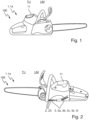
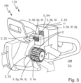
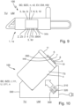
- Fig. 1 to 4 , 5 , 9 and 10 show a system 100 according to the invention for determining information Info about a state Z of a drive motor system 2 and/or a drive accumulator pack 11 of a gardening, forestry and/or construction device 1.
- the system 100 has a detection device 7, a determination device 8, a comparison device 9 and a determination device 10.
- the detection device 7 is designed to detect at least one sensor temperature TS of at least one temperature component 3 of the drive motor system 2 and/or the drive accumulator pack 11 by means of at least one component temperature sensor 4 simultaneously with and/or after operation of the drive motor system 2 and/or the drive accumulator pack 11, in particular and a heater 300 and/or a cooler 310 and/or a fan 320 for heating and/or cooling the drive accumulator pack 11, wherein the temperature component 3 heats up or cools down due to the operation.
- the determination device 8 is designed to determine operating data BD of the operation, wherein the operating data BD are different from the sensor temperature TS.
- the Comparator 9 is designed to compare the detected sensor temperature TS or a variable based on the sensor temperature and the determined operating data BD or a variable TM based on the operating data BD using a temperature model MOD, wherein the temperature model MOD is based on at least one model state AZyes of the drive motor system 2 and/or the drive accumulator pack 11.
- the determination device 10 is designed to determine the information Info depending on a result of the comparison.
- Fig. 5 shows a method according to the invention for determining the information Info about the state Z of the drive motor system 2 and/or the drive accumulator pack 11 of the gardening, forestry and/or construction device 2, in particular by means of the system 100.
- the method has the steps: detecting the at least one sensor temperature TS of the at least one temperature component 3 of the drive motor system 2 and/or the drive accumulator pack 11 by means of the at least one component temperature sensor 4 simultaneously with and/or after the operation of the drive motor system 2 and/or the drive accumulator pack 11, in particular and the heater 300 and/or the cooler 310 and/or the fan 320 for heating and/or cooling the drive accumulator pack 11, in particular by means of the detection device 7.
- the temperature component 3 heats up or cools down due to the operation.
- the operating data BD are different from the sensor temperature TS. Comparing the recorded sensor temperature TS or the value based on the sensor temperature and the determined operating data BD or the value TM based on the operating data BD by means of the temperature model MOD, in particular by means of the comparison device 9.
- the temperature model MOD is based on the at least one model state AZyes of the drive motor system 2 and/or the drive accumulator pack 11. Determining the information Info depending on the result of the comparison, in particular by means of the determination device 10.
- the system 100 comprises the drive motor system 2 and/or the drive accumulator pack 11, in particular the gardening, forestry and/or construction equipment 1, in particular and the heater 300 and/or the cooler 310 and/or the fan 320, in particular a charger 330 for charging the drive accumulator pack 11 comprising the heater 300 and/or the cooler 310 and/or the fan 320.
- the gardening, forestry and/or construction tool 1 is a saw 1a.
- the gardening, forestry and/or Construction equipment may be a pole pruner or a brush cutter or a blower or a cut-off grinder or a lawn mower, in particular a robotic lawn mower.
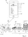
- the system 100 comprises a mobile detection device 101, in particular in the form of a smartphone 101a, as in Fig. 4
- the detection device 101 is separate from the temperature component 3, in particular the drive motor system 2 and/or the drive accumulator pack 11, in particular the gardening, forestry and/or construction processing device 1.
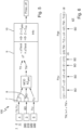
- the drive accumulator pack 11 and, in the Fig. 1 to 4 thus, the gardening, forestry and/or construction processing device 1 and the determination device 101, in particular, each have the detection device 7, the determination device 8, the comparison device 9 and the determination device 10.
- the drive motor system or the drive accumulator pack or the gardening, forestry and/or construction processing device or the determination device can have the detection device, the determination device, the comparison device and/or the determination device.
- the temperature component 3 is an electric drive motor 3a or a motor electronics 3b, in particular a motor power electronics 3c, or a battery cell 3e or a pack electronics 3f, in particular a pack power electronics 3g.
- the temperature component 3 is an internal combustion engine 3d.
- Fig. 1 to 4 exactly four temperature components 3 are present or provided.
- Fig. 9 only a single temperature component 3 is present or provided. In general, only a single temperature component or at least two temperature components can be present or provided.
- Fig. 1 to 4 Exactly three component temperature sensors 4 are present or provided.
- Fig. 9 only a single component temperature sensor 4 is present or provided. In general, only a single component temperature sensor or at least two component temperature sensors can be present or provided.
- the operating data BD are related to an energy supply Pzu of the operation and/or a heat dissipation Pab due to the operation, as in Fig. 6 shown.
- the operating data BD contain an operating runtime BZD and/or an operating current I, in particular a motor current I2 and/or a pack current I11, and/or an operating voltage U, in particular a motor voltage and/or a pack voltage U11, and/or a rotational speed n, in particular a motor rotational speed n2.
- the operating data BD have an operating time BZD and/or a speed n, in particular an engine speed n2, and/or an injection ratio EV and/or an injection quantity EM and/or a fuel quantity KM.
- the method comprises: determining the information Info about the state Z5 of a state component 5 of the drive motor system 2 and/or of the drive accumulator pack 11 depending on the result of the comparison, in particular by means of the determination device 10.
- Fig. 1 to 4 and 10 the state component 5 of the electric drive motor, in particular a motor bearing and/or a rotor and/or a stator and/or at least one coil, or the motor electronics, in particular the motor power electronics, or an air filter 5a, in particular a cooling air filter 5b, or an air filter grille 5c or a cooler 5d, in particular a heat sink 5e, in particular cooling fins 5f, and/or a cooling fan 5g, in particular a fan wheel 5h, and/or a cooler bearing 5j, or an air inlet and/or outlet 5k, in particular an air inlet and/or outlet opening 5I, or a pack shaft 5m or the accumulator cell or the pack electronics, in particular the pack power electronics.
- the motor electronics in particular the motor power electronics
- an air filter 5a in particular a cooling air filter 5b, or an air filter grille 5c or a cooler 5d
- a heat sink 5e in particular cooling fins 5f
- a cooling fan 5g in
- the state component 5 is the internal combustion engine, in particular an engine bearing, or a control unit or an air filter 5a, in particular a combustion air filter 5i and/or a cooling air filter, or an air filter grille or a cooler, in particular a cooling body, in particular cooling fins, and/or a cooling fan, in particular a fan wheel, and/or a cooler bearing, or an air inlet and/or outlet, in particular an air inlet and/or outlet opening.
- the drive motor system 2 and/or the drive accumulator pack 11 have/have several state components 5a, 5c, 5d, 5g, 5m.
- the drive motor system and/or the drive accumulator pack can, in particular, each have only a single state component.
- the method also comprises: determining an ambient temperature TU of an environment UM of the drive motor system 2 and/or the drive accumulator pack 11, in particular of the gardening, forestry and/or construction processing device 1, in particular by means of the system 100. Comparing the recorded sensor temperature TS or the variable based on the sensor temperature and the determined operating data or the variable TM based on the operating data BD by means of the temperature model MOD taking into account the determined ambient temperature TU, as in Fig. 6 shown.
- the method comprises: detecting the ambient temperature TU by means of the at least one component temperature sensor 4 prior to operation.
- the detection device 101 is designed to detect, in particular to record, the ambient temperature TU of the environment UM of the drive motor system 2 and/or the drive accumulator pack 11, in particular of the gardening, forestry and/or construction processing device 1, as in Fig. 4 shown.
- the comparison device 9 is designed to compare the detected sensor temperature TS or the variable based on the sensor temperature and the determined operating data BD or the variable TM based on the operating data BD by means of the temperature model MOD taking into account the determined ambient temperature TU.
- the detection device 101 has an ambient temperature sensor 6 for detecting the ambient temperature TU.
- the method comprises: detecting the ambient temperature TU by means of the at least one ambient temperature sensor 6.
- the ambient temperature sensor 6 is different from the component temperature sensor 4 and/or separate from the temperature component 3, in particular the drive motor system 2 and/or the drive accumulator pack 11, in particular the gardening, forestry and/or construction processing device 1.
- the method may additionally or alternatively comprise: receiving the ambient temperature, in particular by means of the determination device.
- the ambient temperature TU detected by means of the component temperature sensor 4 and the ambient temperature TU detected by means of the ambient temperature sensor 6 are averaged.
- the comparison is carried out taking into account the averaged ambient temperature TU.
- this can be fulfilled under the condition that the ambient temperature TU detected by means of the component temperature sensor 4 and the ambient temperature TU detected by means of the ambient temperature sensor 6 have only a small variance (a high variance indicates heating in the sun, cooling/heating due to a change in position, ).
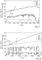
- the method comprises: determining, in particular calculating, at least one model temperature TM or a size representative of the model temperature of the at least one temperature component 3 based on the determined operating data BD by means of the temperature model MOD, as in Fig. 6 shown, in particular by means of the comparison device 9. Comparing the detected sensor temperature TS or the size with the determined model temperature TM or the determined size, as in Fig. 7 and 8 shown, in particular by means of the comparison device 9.
- the model temperature TM at a time t+1 is determined, in particular calculated, in particular repeated several times or in finite steps based on the model temperature TM at a previous time t, in particular a time unit or a time interval ⁇ t in advance, and the determined operating data BD, in particular for the time unit ⁇ t.
- the temperature model MOD or the formula is based on the energy supply PU and the heat dissipation Pab.
- the temperature model MOD or the formula, in particular the energy supply PU is based on Joule heat, in particular generated by the operating current I, in particular the pack current 111, and switching losses, in particular generated by the operating current I, in particular the motor current I2, and the operating voltage U, in particular the pack voltage U11, and frictional heat, in particular generated by the speed n, in particular the motor speed n2.
- the temperature model MOD or the formula, in particular the heat dissipation Pab, in particular to the environment is based on convection, in particular convection cooling, in particular through the environment, in particular with the ambient temperature TU, and ventilation cooling, in particular through the environment, in particular with the ambient temperature TU, and the speed n, in particular the engine speed n2.
- the Joule heat is determined or taken into account with two model parameters c1 and c6 of the temperature model MOD.
- the frictional heat is determined or taken into account with a model parameter c2.
- the convection cooling is determined or taken into account with a model parameter c3.
- the ventilation cooling is determined or taken into account with a model parameter c4.
- a heat capacity (fixed constant for the corresponding temperature component 3) is determined or taken into account with a model parameter c5, in particular in order to be able to determine, in particular calculate, a change in the model temperature TM per unit of time ⁇ t.
- the method further comprises: determining, in particular calculating, a deviation ⁇ T of the recorded sensor temperature TS or the variable based on the sensor temperature and the determined operating data BD or the variable TM based on the operating data BD by means of the temperature model MOD, in particular based on a designated model state AZyes, from the determined model temperature TM or the variable representative of the model temperature, in particular repeated several times or in finite steps, as in Fig. 7 and 8 shown, in particular by means of the comparison device 9. Determining the information Info as a function of the determined deviation ⁇ T, in particular by means of the determination device 10.
- a deviation limit value ⁇ Tlimit in particular of e.g. five degrees Celsius
- a non-normal state Zno if the determined deviation ⁇ T is equal to or greater than the deviation limit value ⁇ Tlimit.
- Fig. 7 corresponds, in particular, to the sensor temperature TS of the model temperature TM.
- the deviation ⁇ T is smaller than the deviation limit value ⁇ Tlimit.
- the information Info about the intended state Zyes is determined.
- the sensor temperature TS deviates from the model temperature TM, in particular the sensor temperature TS is higher than the model temperature TM, especially with time.
- the deviation ⁇ T is equal to or greater than the deviation limit value ⁇ Tlimit, in particular after e.g. sixty seconds. In this way, the information Info about the non-conforming condition Zno is determined.
- the deviation ⁇ T of the sensor temperature TS from the model temperature TM is determined, in particular calculated.
- the deviation limit value ⁇ Tlimit is specified in such a way that the information Info about the intended state Zyes and/or the non-intended state Zno can be determined reliably or safely.
- a temporal change, in particular a gradient, of the sensor temperature and a temporal change, in particular a gradient, of the model temperature can be compared, in particular a deviation of the changes can be determined, in particular calculated.
- a deviation of the changes can be determined, in particular calculated.
- the information, in particular about the non-intended state can be determined as a function of the magnitude of an exceedance of the deviation limit value by the deviation, e.g. from greater than zero percent to one hundred percent non-intended state.
- condition Z, Zno in particular the non-intended condition, is a contamination, maintenance and/or defect condition VWDZ.
- the state Z is the intended state Zyes.
- the drive motor system 2 and/or the drive accumulator pack 11, in particular the state component(s) 5, are clean, maintenance-free and non-defective or intact.
- the energy supply Pzu and the heat dissipation Pab, in particular, are in accordance with their intended purpose.
- the sensor temperature TS corresponds to the model temperature TM.
- the state Z is the non-intended state Zno.
- the energy supply Pzu and/or the heat dissipation Pab are not as intended.
- the energy supply Pzu is higher than intended and/or the heat dissipation Pab is lower or less than intended.
- the sensor temperature TS deviates from the model temperature TM, in particular, the sensor temperature TS is higher than the model temperature TM.
- the model temperature TM can be set to the current sensor temperature TS, especially repeatedly, after a specified or certain period of time or a specified or certain event (e.g. standstill, too low or too little speed, too low or too little load, etc.). This can make it possible to counteract a drift in the model temperature TM, especially due to a simplification of reality by the temperature model MOD.
- a specified or certain event e.g. standstill, too low or too little speed, too low or too little load, etc.
- the method comprises: lowering at least one maximum released drive and/or charging power Pmax, in particular for at least one assigned speed n, of the drive motor system 2 and/or the drive accumulator pack 11, in particular switching off the drive motor system 2 and/or the drive accumulator pack 11, depending on the determined information Info, in particular about the non-intended state Zno, in particular by means of the system 100, in particular by means of the determination device 10.
- system 100 in particular the drive motor system 2 and/or the drive accumulator pack 11 and/or the gardening, forestry and/or construction processing device 1 and/or the detection device 101, in particular each have an output and transmission device 200 for outputting and/or transmitting the information Info, as in Fig. 4 shown.
- the method further comprises the step of outputting and/or transmitting the information Info, in particular by means of the output and transmission device 200.
- the information Info comprises the specific state Z and/or a reduction and/or shutdown indication AAH and/or a cleaning, maintenance and/or repair indication RWRH.
- the method comprises: identifying the state component 5a, 5c, 5d, 5g, 5m having the non-determined state Zno, in particular by varying the at least one model parameter c1, c2, c3, c4, c5, c6 of the temperature model MOD and/or by means of a, in particular extended, Kalman filter KF, in particular by means of the comparison device 9.
- the information is about the identified state component, in particular information info comprises the state component.
- the air filter 5a may be dirty, in particular clogged, and thus not well permeable
- the air filter grille 5c may be dirty, in particular clogged, and thus not well permeable
- the cooler 5d may be dirty, in particular filthy, and thus not well dissipating heat
- the cooling fan 5g may be defective and thus not well dissipating heat and/or generating heat
- the packing shaft 5m may be dirty, in particular clogged, and thus not well permeable.
- the convection cooling and/or the ventilation cooling may not be as intended, in particular lower or less, and/or the Joule heat and/or the frictional heat may not be as intended, in particular higher.
- temperature models MOD can be provided or present for the several temperature components 3, in particular each.
- the temperature models MOD can be parameterized for the temperature components 3, in particular each, in particular such that they depict the temperature behavior for different states Z, Zyes, Zno of the drive motor system 2 and/or the drive accumulator packs 11.
- the gardening, forestry and/or construction processing device 1 and the detection device 101 are designed to interact, in particular work together, in particular are in signal connection.
- the invention provides an advantageous method for determining information about a state of a drive motor system and/or a drive accumulator pack of a gardening, forestry and/or construction processing device and an advantageous system for determining information about a state of a drive motor system and/or a drive accumulator pack of a gardening, forestry and/or construction processing device, wherein the method and the system each have improved properties, in particular more functionalities.
Landscapes
- Engineering & Computer Science (AREA)
- Life Sciences & Earth Sciences (AREA)
- Physics & Mathematics (AREA)
- Environmental Sciences (AREA)
- Chemical & Material Sciences (AREA)
- Combustion & Propulsion (AREA)
- Mechanical Engineering (AREA)
- General Engineering & Computer Science (AREA)
- General Physics & Mathematics (AREA)
- Automation & Control Theory (AREA)
- Biodiversity & Conservation Biology (AREA)
- Ecology (AREA)
- Forests & Forestry (AREA)
- Evolutionary Computation (AREA)
- Mathematical Physics (AREA)
- Microelectronics & Electronic Packaging (AREA)
- Power Engineering (AREA)
- Artificial Intelligence (AREA)
- Secondary Cells (AREA)
- Control Of Electric Motors In General (AREA)
- Cooling Or The Like Of Electrical Apparatus (AREA)
Claims (13)
- Procédé permettant de déterminer une information (Info) concernant un état (Z) non conforme d'un système de moteur d'entraînement (2) et/ou d'un bloc d'accumulateur d'entraînement (11) d'un appareil (1) de jardinage, de foresterie et/ou de bricolage, le procédé comprenant les étapes consistant à :- détecter au moins une température de capteur (TS) d'au moins un composant thermique (3) du système de moteur d'entraînement (2) et/ou du bloc d'accumulateur d'entraînement (11) au moyen d'au moins un capteur de température de composant (4) en même temps que, et/ou après un fonctionnement du système de moteur d'entraînement (2) et/ou du bloc d'accumulateur d'entraînement (11), dans lequel le composant thermique (3) se réchauffe ou se refroidit en raison du fonctionnement,- établir des données de fonctionnement (BD) du fonctionnement, les données de fonctionnement (BD) étant différentes de la température de capteur (TS),- établir au moins une température de modèle (TM) ou une grandeur représentative de la température de modèle dudit au moins un composant thermique (3) sur la base des données de fonctionnement (BD) établies au moyen d'un modèle de température (MOD), etcomparer la température de capteur (TS) détectée ou une grandeur basée sur la température de capteur et la température de modèle (TM) établie ou la grandeur établie représentative de la température de modèle,dans lequel le modèle de température (MOD) est basé sur au moins un état de modèle (AZyes) du système de moteur d'entraînement (2) et/ou du bloc d'accumulateur d'entraînement (11), et- déterminer l'information (Info) en fonction d'un résultat de la comparaison.
- Procédé selon la revendication 1,- dans lequel les données de fonctionnement (BD) sont liées à un apport en énergie (Pzu) du fonctionnement et/ou à une dissipation de chaleur (Pab) en raison du fonctionnement, en particulier dans lequel les données de fonctionnement (BD) présentent une durée de temps de fonctionnement (BZD) et/ou un courant de fonctionnement (I) et/ou une tension de fonctionnement (U) et/ou une vitesse de rotation (n) et/ou un rapport d'injection (EV) et/ou une quantité d'injection (EM) et/ou une quantité de carburant (KM).
- Procédé selon l'une quelconque des revendications précédentes,- dans lequel le composant thermique (3) est un moteur d'entraînement électrique (3a) ou un moteur d'entraînement thermique (3d) ou une électronique de moteur (3b), en particulier une électronique de puissance de moteur (3c), ou une cellule d'accumulateur (3e) ou une électronique de bloc (3f), en particulier une électronique de puissance de bloc (3g).
- Procédé selon la revendication 1, le procédé présentant les étapes consistant à :- établir un écart (ΔT) de la température de capteur (TS) détectée ou de la grandeur basée sur la température de capteur par rapport à la température de modèle (TM) établie ou à la grandeur établie représentative de la température de modèle, et- déterminer l'information (Info) en fonction de l'écart (ΔT) établi, en particulier déterminer l'information (Info) concernant un état conforme (Zyes) si l'écart (ΔT) établi est inférieur à une valeur limite d'écart (ΔTlimit) et/ou un état non conforme (Zno) si l'écart (ΔT) établi est égal ou supérieur à la valeur limite d'écart (ΔTlimit).
- Procédé selon l'une quelconque des revendications précédentes,
le procédé présentant l'étape consistant à :
abaisser au moins une puissance d'entraînement et/ou de recharge libérée maximale (Pmax), en particulier pour au moins une vitesse de rotation (n) associée, du système de moteur d'entraînement (2) et/ou du bloc d'accumulateur d'entraînement (11), en particulier mettre hors tension le système de moteur d'entraînement (2) et/ou le bloc d'accumulateur d'entraînement (11), en fonction de l'information (Info) déterminée, en particulier concernant l'état non conforme (Zno). - Procédé selon l'une quelconque des revendications précédentes, en particulier selon la revendication 5,
le procédé présentant l'étape consistant à :- sortir et/ou transmettre l'information (Info), en particulier dans lequel l'information (Info) présente une indication d'abaissement et/ou de mise hors tension (AAH) et/ou une indication de nettoyage, de maintenance et/ou de réparation (RWRH). - Procédé selon l'une quelconque des revendications précédentes, le procédé présentant l'étape consistant à :- déterminer l'information (Info) concernant l'état (Z5) d'un composant d'état (5) du système de moteur d'entraînement (2) et/ou du bloc d'accumulateur d'entraînement (11) en fonction du résultat de la comparaison, en particulier dans lequel le composant d'état (5) est un moteur d'entraînement électrique ou un moteur d'entraînement thermique, en particulier un palier de moteur et/ou un rotor et/ou un stator et/ou au moins une bobine, ou une électronique de moteur, en particulier une électronique de puissance de moteur, ou un appareil de commande ou un filtre à air (5a), en particulier un filtre à air de combustion (5i) et/ou un filtre à air de refroidissement (5b), ou une grille de filtre à air (5c) ou un refroidisseur (5d), en particulier un dissipateur thermique (5e), en particulier des ailettes de refroidissement (5f), et/ou un ventilateur de refroidissement (5g), en particulier une roue de ventilateur (5h), et/ou un palier de refroidisseur (5j), ou une entrée et/ou sortie d'air (5k), en particulier une ouverture d'entrée et/ou de sortie d'air (51), ou un compartiment de bloc (5m) ou une cellule d'accumulateur ou une électronique de bloc, en particulier une électronique de puissance de bloc.
- Procédé selon les revendications 4 et 7,- dans lequel le système de moteur d'entraînement (2) et/ou le bloc d'accumulateur d'entraînement (11) présente(nt) plusieurs composants d'état (5a, 5c, 5d, 5g, 5m), et- le procédé présentant les étapes consistant à :- déterminer l'information (Info) concernant l'état non conforme (Zno) si l'écart (ΔT) établi est égal ou supérieur à une valeur limite d'écart (ΔTlimit), et- identifier le composant d'état (5a, 5c, 5d, 5g, 5m) présentant l'état non conforme (Z5no), en particulier en faisant varier au moins un paramètre de modèle (c1, c2, c3, c4, c5, c6) du modèle de température (MOD) et/ou au moyen d'un filtre de Kalman (KF), en particulier étendu.
- Procédé selon l'une quelconque des revendications précédentes, le procédé présentant l'étape consistant à :- établir une température ambiante (TU) d'un environnement (UM) du système de moteur d'entraînement (2) et/ou du bloc d'accumulateur d'entraînement (11), en particulier de l'appareil (1) de jardinage, de foresterie et/ou de bricolage, et- comparer la température de capteur (TS) détectée ou une grandeur basée sur la température de capteur et la température de modèle (TM) établie ou la grandeur établie représentative de la température de modèle au moyen du modèle de température (MOD) en tenant compte de la température ambiante (TU) établie.
- Procédé selon la revendication 9, le procédé présentant l'étape consistant à :- détecter la température ambiante (TU) au moyen du au moins un capteur de température de composant (4) avant le fonctionnement.
- Procédé selon la revendication 9 ou 10, le procédé présentant l'étape consistant à :- détecter la température ambiante (TU) au moyen d'au moins un capteur de température ambiante (6), le capteur de température ambiante (6) étant différent du capteur de température de composant (4) et/ou séparé du composant thermique (3), en particulier du système de moteur d'entraînement (2) et/ou du bloc d'accumulateur d'entraînement (11), en particulier de l'appareil (1) de jardinage, de foresterie et/ou de bricolage.
- Système (100) permettant de déterminer une information (Info) concernant un état non conforme (Z) d'un système de moteur d'entraînement (2) et/ou d'un bloc d'accumulateur d'entraînement (11) d'un appareil (1) de jardinage, de foresterie et/ou de bricolage, en particulier pour exécuter un procédé selon l'une quelconque des revendications précédentes, le système (100) présentant :- un dispositif de détection (7), le dispositif de détection (7) étant réalisé pour détecter au moins une température de capteur (TS) d'au moins un composant thermique (3) du système de moteur d'entraînement (2) et/ou du bloc d'accumulateur d'entraînement (11) au moyen d'au moins un capteur de température de composant (4) en même temps et/ou après un fonctionnement du système de moteur d'entraînement (2) et/ou du bloc d'accumulateur d'entraînement (11), dans lequel le composant thermique (3) se réchauffe ou se refroidit en raison du fonctionnement,- un dispositif d'établissement (8), le dispositif d'établissement (8) étant réalisé pour établir des données de fonctionnement (BD) du fonctionnement, les données de fonctionnement (BD) étant différentes de la température de capteur (TS),- un dispositif de comparaison (9), le dispositif de comparaison (9) étant réalisé pour établir au moins une température de modèle (TM) ou une grandeur représentative de la température de modèle dudit au moins un composant thermique (3) sur la base des données de fonctionnement (BD) établies au moyen d'un modèle de température (MOD), etcomparer la température de capteur (TS) détectée ou une grandeur basée sur la température de capteur et la température de modèle (TM) établie ou la grandeur établie représentative de la température de modèle,dans lequel le modèle de température (MOD) est basé sur au moins un état de modèle (AZyes) du système de moteur d'entraînement (2) et/ou du bloc d'accumulateur d'entraînement (11), et- un dispositif de détermination (10), le dispositif de détermination (10) étant réalisé pour déterminer l'information (Info) en fonction d'un résultat de la comparaison.
- Système (100) selon la revendication 12, le système (100) présentant :- le système de moteur d'entraînement (2) et/ou le bloc d'accumulateur d'entraînement (11), en particulier l'appareil (1) de jardinage, de foresterie et/ou de bricolage, et/ou- un appareil d'établissement mobile (101), l'appareil d'établissement (101) étant séparé du composant thermique (3), en particulier du système de moteur d'entraînement (2) et/ou du bloc d'accumulateur d'entraînement (11), en particulier de l'appareil de jardinage, de foresterie et/ou de bricolage (1), et dans lequel l'appareil d'établissement (101) est réalisé pour établir une température ambiante (TU) d'un environnement (UM) du système de moteur d'entraînement (2) et/ou du bloc d'accumulateur d'entraînement (11), en particulier de l'appareil (1) de jardinage, de foresterie et/ou de bricolage, et dans lequel le dispositif de comparaison (9) est réalisé pour comparer la température de capteur (TS) détectée ou la grandeur basée sur la température de capteur et la température de modèle (TM) établie ou la grandeur établie représentative de la température de modèle au moyen du modèle de température (MOD) en tenant compte de la température ambiante (TU) établie.
Priority Applications (3)
| Application Number | Priority Date | Filing Date | Title |
|---|---|---|---|
| EP20211296.7A EP4009125B1 (fr) | 2020-12-02 | 2020-12-02 | Procede de determination d'informations concernant une condition d'un systeme de moteur d'entrainement et/ou d'un pack d'accumulateur d'entrainement d'une machine de jardinage, de foresterie et/ou de construction et d'un systeme pour determiner des informations sur l'etat d'un systeme de moteur d'entrainement et/ou de traitement de construction de systeme de moteur d'entrainement équipement |
| US17/457,200 US11530663B2 (en) | 2020-12-02 | 2021-12-01 | Method for determining information about a state of a drive motor system and/or of a drive battery pack of a gardening, forestry and/or construction device, and system for determining information about a state of a drive motor system and/or of a drive battery pack of a gardening, forestry and/or construction device |
| CN202111461814.1A CN114598111A (zh) | 2020-12-02 | 2021-12-02 | 确定马达系统和/或蓄电池组的状态信息的方法和系统 |
Applications Claiming Priority (1)
| Application Number | Priority Date | Filing Date | Title |
|---|---|---|---|
| EP20211296.7A EP4009125B1 (fr) | 2020-12-02 | 2020-12-02 | Procede de determination d'informations concernant une condition d'un systeme de moteur d'entrainement et/ou d'un pack d'accumulateur d'entrainement d'une machine de jardinage, de foresterie et/ou de construction et d'un systeme pour determiner des informations sur l'etat d'un systeme de moteur d'entrainement et/ou de traitement de construction de systeme de moteur d'entrainement équipement |
Publications (2)
| Publication Number | Publication Date |
|---|---|
| EP4009125A1 EP4009125A1 (fr) | 2022-06-08 |
| EP4009125B1 true EP4009125B1 (fr) | 2025-01-29 |
Family
ID=73694880
Family Applications (1)
| Application Number | Title | Priority Date | Filing Date |
|---|---|---|---|
| EP20211296.7A Active EP4009125B1 (fr) | 2020-12-02 | 2020-12-02 | Procede de determination d'informations concernant une condition d'un systeme de moteur d'entrainement et/ou d'un pack d'accumulateur d'entrainement d'une machine de jardinage, de foresterie et/ou de construction et d'un systeme pour determiner des informations sur l'etat d'un systeme de moteur d'entrainement et/ou de traitement de construction de systeme de moteur d'entrainement équipement |
Country Status (3)
| Country | Link |
|---|---|
| US (1) | US11530663B2 (fr) |
| EP (1) | EP4009125B1 (fr) |
| CN (1) | CN114598111A (fr) |
Families Citing this family (3)
| Publication number | Priority date | Publication date | Assignee | Title |
|---|---|---|---|---|
| EP4234911A1 (fr) * | 2022-02-25 | 2023-08-30 | Andreas Stihl AG & Co. KG | Procédé de détermination des informations sur une modification d'un appareil mobile de jardinage, de foresterie, de construction ou de traitement du sol, appareil mobile de jardinage, de foresterie, de construction ou de traitement du sol et système |
| WO2025034240A1 (fr) * | 2023-08-10 | 2025-02-13 | Itt Manufacturing Enterprises Llc | Détection de température à double capteur |
| CN116883410B (zh) * | 2023-09-08 | 2023-11-17 | 四川爱麓智能科技有限公司 | 一种磨斑自动化检测与评价的方法、系统以及设备 |
Citations (14)
| Publication number | Priority date | Publication date | Assignee | Title |
|---|---|---|---|---|
| JPH1077838A (ja) | 1996-08-30 | 1998-03-24 | Hitachi Constr Mach Co Ltd | ラジエータシャッター制御装置 |
| US20030101947A1 (en) | 2000-04-19 | 2003-06-05 | Klaus Ries-Mueller | Cooling system for a motor vehicle comprising a closing unit for the cooling airflow |
| WO2007044930A2 (fr) | 2005-10-12 | 2007-04-19 | Black & Decker Inc. | Methodologies de commande et de protection pour module de commande de moteur |
| US20090103263A1 (en) | 2007-10-18 | 2009-04-23 | Hilti Aktiengesellschaft | Hand-held electric power tool with monitoring of motor temperature |
| US20110253102A1 (en) | 2010-01-12 | 2011-10-20 | Walbro Engine Management, L.L.C. | System for supplementary fuel supply |
| WO2012012511A1 (fr) | 2010-07-20 | 2012-01-26 | Vos David W | Système et procédé pour commander un moteur à combustion interne |
| WO2012122136A2 (fr) | 2011-03-04 | 2012-09-13 | Blount, Inc. | Outil alimenté par accumulateur |
| US20170087976A1 (en) | 2015-09-29 | 2017-03-30 | Kubota Corporation | Work Vehicle |
| US20170276572A1 (en) | 2016-03-23 | 2017-09-28 | Chervon (Hk) Limited | Power tool system |
| US20190156226A1 (en) * | 2017-11-21 | 2019-05-23 | Institute For Information Industry | Equipment maintenance prediction system and operation method thereof |
| DE102018119134A1 (de) | 2018-08-07 | 2020-02-13 | Metabowerke Gmbh | Verfahren zum Betreiben eines Elektrowerkzeugs |
| US20200263622A1 (en) * | 2019-02-19 | 2020-08-20 | GM Global Technology Operations LLC | Data sensing and estimation |
| US20200319259A1 (en) | 2019-04-03 | 2020-10-08 | Ge Global Sourcing Llc | Deviation detection system for energy storage system |
| EP3838498A1 (fr) | 2019-12-17 | 2021-06-23 | Metabowerke GmbH | Outil électrique, agencement de mesure et procédé de fonctionnement d'un outil électrique |
Family Cites Families (32)
| Publication number | Priority date | Publication date | Assignee | Title |
|---|---|---|---|---|
| DE3422485A1 (de) | 1984-06-16 | 1985-12-19 | Bsg Schalttechnik Gmbh & Co Kg, 7460 Balingen | Verfahren und vorrichtung zur strombegrenzung eines elektromotors |
| JPH10337084A (ja) * | 1997-05-30 | 1998-12-18 | Aisin Seiki Co Ltd | スイッチングモジュ−ルの過熱保護装置 |
| US6296065B1 (en) | 1998-12-30 | 2001-10-02 | Black & Decker Inc. | Dual-mode non-isolated corded system for transportable cordless power tools |
| DE10001713A1 (de) * | 2000-01-18 | 2001-07-19 | Bosch Gmbh Robert | Verfahren zur Fehlererkennung eines Kühlsystems eines Kraftfahrzeug-Motors |
| US6667869B2 (en) * | 2000-02-24 | 2003-12-23 | Acuity Imaging, Llc | Power control system and method for illumination array |
| US6719396B2 (en) * | 2001-08-31 | 2004-04-13 | Seiko Epson Corporation | Motor control method in recording apparatus and recording apparatus |
| JP2006230037A (ja) * | 2005-02-15 | 2006-08-31 | Toyota Motor Corp | 作動装置および作動機器の制御方法 |
| US7551411B2 (en) | 2005-10-12 | 2009-06-23 | Black & Decker Inc. | Control and protection methodologies for a motor control module |
| DE102008007786A1 (de) | 2008-02-06 | 2009-08-13 | Andreas Stihl Ag & Co. Kg | Handgeführtes Arbeitsgerät |
| CA2775834C (fr) | 2009-09-29 | 2017-01-03 | Husqvarna Ab | Moteur electrique et procede de regulation associe |
| DE102009054400B4 (de) * | 2009-11-24 | 2020-07-02 | Continental Automotive Gmbh | Auswerteeinrichtung, System und Verfahren zum Überprüfen einer Einrichtung eines Kraftfahrzeugs |
| DE102011010224A1 (de) | 2011-02-03 | 2012-08-09 | Festool Gmbh | Hand-Werkzeugmaschine mit einem temperaturabhängigen Sensor |
| DE102011103797B4 (de) * | 2011-06-01 | 2020-08-20 | Jungheinrich Aktiengesellschaft | Verfahren zur Bestimmung einer Temperatur |
| DE102012211580A1 (de) | 2012-07-04 | 2014-01-09 | Robert Bosch Gmbh | Hand-Werkzeugmaschine und Verfahren zum Betrieb einer Hand-Werkzeugmaschine |
| DE102012112833B4 (de) | 2012-12-21 | 2024-06-06 | Robert Bosch Gmbh | Werkzeugmaschine |
| DE102012224429A1 (de) | 2012-12-27 | 2014-07-03 | Robert Bosch Gmbh | Werkzeugmaschinenfluidstromerzeugungsvorrichtung |
| JP5628994B2 (ja) * | 2013-01-21 | 2014-11-19 | ファナック株式会社 | モータがオーバーヒート温度に達するまでの時間を推定する時間推定手段を有する工作機械の制御装置 |
| DE202013101812U1 (de) | 2013-04-26 | 2014-08-06 | Makita Corporation | Luftfilterzustandsmessvorrichtung |
| DE102013212022A1 (de) | 2013-06-25 | 2015-01-08 | Robert Bosch Gmbh | Absaugvorrichtung, insbesondere Handwerkzeugmaschinenabsaugvorrichtung |
| US10131042B2 (en) | 2013-10-21 | 2018-11-20 | Milwaukee Electric Tool Corporation | Adapter for power tool devices |
| US10060827B2 (en) | 2014-01-17 | 2018-08-28 | Kohler Co. | Fleet management system |
| DE102014209032A1 (de) | 2014-01-27 | 2015-07-30 | Robert Bosch Gmbh | Werkzeugmaschinenvorrichtung |
| JP5863919B1 (ja) * | 2014-09-30 | 2016-02-17 | ファナック株式会社 | 工作機械の制御装置 |
| DE102015217053A1 (de) | 2015-09-07 | 2017-03-09 | Robert Bosch Gmbh | Handwerkzeugmaschine |
| JP6360032B2 (ja) * | 2015-12-24 | 2018-07-18 | ファナック株式会社 | モータ温度及びアンプ温度に応じて動作を変更する機能を有する工作機械の制御装置 |
| US10461674B2 (en) | 2016-08-10 | 2019-10-29 | Makita Corporation | Electric working machine, and method of detecting overload operation thereof |
| DE102017201565A1 (de) | 2017-01-31 | 2018-08-02 | Robert Bosch Gmbh | Zubehörvorrichtung für eine Handwerkzeugmaschine |
| SE540695C2 (en) * | 2017-02-20 | 2018-10-16 | Scania Cv Ab | A system and a method for determining a correct or incorrect position of a temperature sensor of an emission control sys tem |
| EP3424296B1 (fr) * | 2017-07-04 | 2023-11-29 | Andreas Stihl AG & Co. KG | Procédé de détermination d'une information pour régler un composant réglable d'un système d'entraînement de moteur à combustion interne d'un appareil de jardinage et/ou forestier, système d'appareil de jardinage et/ou forestier et appareil de jardinage et/ou forestier |
| WO2019152959A2 (fr) * | 2018-02-05 | 2019-08-08 | Franklin Electric Co., Inc. | Protection contre les pannes pour ensemble pompe-moteur |
| JP6973311B2 (ja) * | 2018-07-03 | 2021-11-24 | オムロン株式会社 | 処理装置 |
| EP3878613B1 (fr) * | 2020-03-09 | 2024-06-26 | Braun GmbH | Rasoir électrique |
-
2020
- 2020-12-02 EP EP20211296.7A patent/EP4009125B1/fr active Active
-
2021
- 2021-12-01 US US17/457,200 patent/US11530663B2/en active Active
- 2021-12-02 CN CN202111461814.1A patent/CN114598111A/zh active Pending
Patent Citations (14)
| Publication number | Priority date | Publication date | Assignee | Title |
|---|---|---|---|---|
| JPH1077838A (ja) | 1996-08-30 | 1998-03-24 | Hitachi Constr Mach Co Ltd | ラジエータシャッター制御装置 |
| US20030101947A1 (en) | 2000-04-19 | 2003-06-05 | Klaus Ries-Mueller | Cooling system for a motor vehicle comprising a closing unit for the cooling airflow |
| WO2007044930A2 (fr) | 2005-10-12 | 2007-04-19 | Black & Decker Inc. | Methodologies de commande et de protection pour module de commande de moteur |
| US20090103263A1 (en) | 2007-10-18 | 2009-04-23 | Hilti Aktiengesellschaft | Hand-held electric power tool with monitoring of motor temperature |
| US20110253102A1 (en) | 2010-01-12 | 2011-10-20 | Walbro Engine Management, L.L.C. | System for supplementary fuel supply |
| WO2012012511A1 (fr) | 2010-07-20 | 2012-01-26 | Vos David W | Système et procédé pour commander un moteur à combustion interne |
| WO2012122136A2 (fr) | 2011-03-04 | 2012-09-13 | Blount, Inc. | Outil alimenté par accumulateur |
| US20170087976A1 (en) | 2015-09-29 | 2017-03-30 | Kubota Corporation | Work Vehicle |
| US20170276572A1 (en) | 2016-03-23 | 2017-09-28 | Chervon (Hk) Limited | Power tool system |
| US20190156226A1 (en) * | 2017-11-21 | 2019-05-23 | Institute For Information Industry | Equipment maintenance prediction system and operation method thereof |
| DE102018119134A1 (de) | 2018-08-07 | 2020-02-13 | Metabowerke Gmbh | Verfahren zum Betreiben eines Elektrowerkzeugs |
| US20200263622A1 (en) * | 2019-02-19 | 2020-08-20 | GM Global Technology Operations LLC | Data sensing and estimation |
| US20200319259A1 (en) | 2019-04-03 | 2020-10-08 | Ge Global Sourcing Llc | Deviation detection system for energy storage system |
| EP3838498A1 (fr) | 2019-12-17 | 2021-06-23 | Metabowerke GmbH | Outil électrique, agencement de mesure et procédé de fonctionnement d'un outil électrique |
Non-Patent Citations (2)
| Title |
|---|
| D14 - Examiner’s notes from telephone conversation of 2024-02-28 |
| OLIVER PRESS: "The Chainsaw Book", 1 May 1976, OLIVER PRESS, Willits, California, ISBN: 0-914400-17-7, article OLIVER PRESS: "Chapter 8: Troubleshooting and Repairs", pages: 59 - 115, XP009564056 |
Also Published As
| Publication number | Publication date |
|---|---|
| CN114598111A (zh) | 2022-06-07 |
| US11530663B2 (en) | 2022-12-20 |
| EP4009125A1 (fr) | 2022-06-08 |
| US20220170425A1 (en) | 2022-06-02 |
Similar Documents
| Publication | Publication Date | Title |
|---|---|---|
| EP4009125B1 (fr) | Procede de determination d'informations concernant une condition d'un systeme de moteur d'entrainement et/ou d'un pack d'accumulateur d'entrainement d'une machine de jardinage, de foresterie et/ou de construction et d'un systeme pour determiner des informations sur l'etat d'un systeme de moteur d'entrainement et/ou de traitement de construction de systeme de moteur d'entrainement équipement | |
| DE102011054144B4 (de) | Regelverfahren zur Detektion von übermäßigem Strom | |
| DE102013216922B4 (de) | Thermische Batteriesysteme und Diagnoseverfahren | |
| EP3699566B1 (fr) | Dispositif et procédé de surveillance d'une température d'une machine électrique | |
| WO2015197483A1 (fr) | Dispositif et procédé de régulation de l'état de charge d'un accumulateur d'énergie électrique | |
| WO2001079671A1 (fr) | Systeme de refroidissement d'un vehicule motorise comportant une unite de fermeture pour le flux d'air de refroidissement | |
| DE102013000220B3 (de) | Verfahren zur Bestimmung einer Temperatur in einem elektrischen Körper, insbesondere in einem Akkumulator, Vorrichtung zur Berechnung der Temperatur, Vorrichtung zur Temperaturregulierung sowie Fahrzeug mit einem elektrischen Körper | |
| DE102012204492B4 (de) | Verfahren zum Überprüfen der Funktionstüchtigkeit von Hydraulikkomponenten im Kühlkreislauf eines Kraftfahrzeuges | |
| DE102013213114A1 (de) | Kühlung eines aufladbaren Energiespeichersystems | |
| DE102019220070A1 (de) | Verfahren zu einer Benutzerinteraktion eines Elektrogeräts und/oder eines Elektrogerätezubehörs und System zu einem Durchführen des Verfahrens | |
| DE102013205791A1 (de) | Kühllüftersteuervorrichtung | |
| CN117341976A (zh) | 一种无人机综合健康管理系统 | |
| CN117763480A (zh) | 一种温度传感器离群识别方法、装置、设备和介质 | |
| DE202008010458U1 (de) | Vorrichtung zum Betreiben eines elektrischen Antriebs | |
| DE102015114119A1 (de) | Lüftungsvorrichtung, Luftfahrzeug, das eine derartige Lüftungsvorrichtung umfasst und zugeordnetes Überwachungsverfahren | |
| DE10203051A1 (de) | Verfahren und Vorrichtung zur temperaturabhängigen Steuerung von Leistung eines Elektrogerätes | |
| US20180001783A1 (en) | Method for setting an operating parameter of batteries | |
| EP4388228B1 (fr) | Dispositif et procédé de détermination d'une température d'une huile au moyen de laquelle une unité d'engrenage d'un véhicule est lubrifiée et refroidie | |
| DE102022210477A1 (de) | Verfahren zur Analyse eines Zustands eines Wechselakkupacks, Wechselakkupack, System und Computerprogramm | |
| DE10220775A1 (de) | Anordnung und Verfahren zur Verbesserung der Ladefähigkeit der Batterie eines Kraftfahrzeugs | |
| EP3736190B1 (fr) | Véhicule hybride et procédé de réglage d'une limite de puissance d'un moteur à combustion interne d'un véhicule hybride | |
| DE102018213370A1 (de) | Verfahren zum Ermitteln einer Temperatur eines Elektromotors einer Werkzeugmaschine und Werkzeugmaschine | |
| DE102021214774A1 (de) | Steuerung einer Heizungs-, Lüftungs- und/oder Klimaanlage eines Fahrzeugs | |
| CN118591474A (zh) | 功率控制方法、装置及电动汽车 | |
| DE102021206574A1 (de) | Verfahren zum Erkennen von Stürzen und/oder unsachgemäßer Handhabung eines elektrochemischen Energiespeichers |
Legal Events
| Date | Code | Title | Description |
|---|---|---|---|
| PUAI | Public reference made under article 153(3) epc to a published international application that has entered the european phase |
Free format text: ORIGINAL CODE: 0009012 |
|
| STAA | Information on the status of an ep patent application or granted ep patent |
Free format text: STATUS: THE APPLICATION HAS BEEN PUBLISHED |
|
| AK | Designated contracting states |
Kind code of ref document: A1 Designated state(s): AL AT BE BG CH CY CZ DE DK EE ES FI FR GB GR HR HU IE IS IT LI LT LU LV MC MK MT NL NO PL PT RO RS SE SI SK SM TR |
|
| STAA | Information on the status of an ep patent application or granted ep patent |
Free format text: STATUS: REQUEST FOR EXAMINATION WAS MADE |
|
| 17P | Request for examination filed |
Effective date: 20221129 |
|
| RBV | Designated contracting states (corrected) |
Designated state(s): AL AT BE BG CH CY CZ DE DK EE ES FI FR GB GR HR HU IE IS IT LI LT LU LV MC MK MT NL NO PL PT RO RS SE SI SK SM TR |
|
| GRAP | Despatch of communication of intention to grant a patent |
Free format text: ORIGINAL CODE: EPIDOSNIGR1 |
|
| STAA | Information on the status of an ep patent application or granted ep patent |
Free format text: STATUS: GRANT OF PATENT IS INTENDED |
|
| INTG | Intention to grant announced |
Effective date: 20240326 |
|
| GRAJ | Information related to disapproval of communication of intention to grant by the applicant or resumption of examination proceedings by the epo deleted |
Free format text: ORIGINAL CODE: EPIDOSDIGR1 |
|
| STAA | Information on the status of an ep patent application or granted ep patent |
Free format text: STATUS: REQUEST FOR EXAMINATION WAS MADE |
|
| GRAP | Despatch of communication of intention to grant a patent |
Free format text: ORIGINAL CODE: EPIDOSNIGR1 |
|
| STAA | Information on the status of an ep patent application or granted ep patent |
Free format text: STATUS: GRANT OF PATENT IS INTENDED |
|
| INTC | Intention to grant announced (deleted) | ||
| INTG | Intention to grant announced |
Effective date: 20240808 |
|
| GRAS | Grant fee paid |
Free format text: ORIGINAL CODE: EPIDOSNIGR3 |
|
| GRAA | (expected) grant |
Free format text: ORIGINAL CODE: 0009210 |
|
| STAA | Information on the status of an ep patent application or granted ep patent |
Free format text: STATUS: THE PATENT HAS BEEN GRANTED |
|
| AK | Designated contracting states |
Kind code of ref document: B1 Designated state(s): AL AT BE BG CH CY CZ DE DK EE ES FI FR GB GR HR HU IE IS IT LI LT LU LV MC MK MT NL NO PL PT RO RS SE SI SK SM TR |
|
| REG | Reference to a national code |
Ref country code: GB Ref legal event code: FG4D Free format text: NOT ENGLISH |
|
| REG | Reference to a national code |
Ref country code: CH Ref legal event code: EP |
|
| REG | Reference to a national code |
Ref country code: DE Ref legal event code: R096 Ref document number: 502020010304 Country of ref document: DE |
|
| REG | Reference to a national code |
Ref country code: IE Ref legal event code: FG4D Free format text: LANGUAGE OF EP DOCUMENT: GERMAN |
|
| REG | Reference to a national code |
Ref country code: NL Ref legal event code: MP Effective date: 20250129 |
|
| PG25 | Lapsed in a contracting state [announced via postgrant information from national office to epo] |
Ref country code: NL Free format text: LAPSE BECAUSE OF FAILURE TO SUBMIT A TRANSLATION OF THE DESCRIPTION OR TO PAY THE FEE WITHIN THE PRESCRIBED TIME-LIMIT Effective date: 20250129 |
|
| PG25 | Lapsed in a contracting state [announced via postgrant information from national office to epo] |
Ref country code: RS Free format text: LAPSE BECAUSE OF FAILURE TO SUBMIT A TRANSLATION OF THE DESCRIPTION OR TO PAY THE FEE WITHIN THE PRESCRIBED TIME-LIMIT Effective date: 20250429 |
|
| PG25 | Lapsed in a contracting state [announced via postgrant information from national office to epo] |
Ref country code: FI Free format text: LAPSE BECAUSE OF FAILURE TO SUBMIT A TRANSLATION OF THE DESCRIPTION OR TO PAY THE FEE WITHIN THE PRESCRIBED TIME-LIMIT Effective date: 20250129 |
|
| PG25 | Lapsed in a contracting state [announced via postgrant information from national office to epo] |
Ref country code: PL Free format text: LAPSE BECAUSE OF FAILURE TO SUBMIT A TRANSLATION OF THE DESCRIPTION OR TO PAY THE FEE WITHIN THE PRESCRIBED TIME-LIMIT Effective date: 20250129 |
|
| PG25 | Lapsed in a contracting state [announced via postgrant information from national office to epo] |
Ref country code: ES Free format text: LAPSE BECAUSE OF FAILURE TO SUBMIT A TRANSLATION OF THE DESCRIPTION OR TO PAY THE FEE WITHIN THE PRESCRIBED TIME-LIMIT Effective date: 20250129 |
|
| REG | Reference to a national code |
Ref country code: LT Ref legal event code: MG9D |
|
| PG25 | Lapsed in a contracting state [announced via postgrant information from national office to epo] |
Ref country code: NO Free format text: LAPSE BECAUSE OF FAILURE TO SUBMIT A TRANSLATION OF THE DESCRIPTION OR TO PAY THE FEE WITHIN THE PRESCRIBED TIME-LIMIT Effective date: 20250429 Ref country code: IS Free format text: LAPSE BECAUSE OF FAILURE TO SUBMIT A TRANSLATION OF THE DESCRIPTION OR TO PAY THE FEE WITHIN THE PRESCRIBED TIME-LIMIT Effective date: 20250529 |
|
| PG25 | Lapsed in a contracting state [announced via postgrant information from national office to epo] |
Ref country code: HR Free format text: LAPSE BECAUSE OF FAILURE TO SUBMIT A TRANSLATION OF THE DESCRIPTION OR TO PAY THE FEE WITHIN THE PRESCRIBED TIME-LIMIT Effective date: 20250129 |
|
| PG25 | Lapsed in a contracting state [announced via postgrant information from national office to epo] |
Ref country code: PT Free format text: LAPSE BECAUSE OF FAILURE TO SUBMIT A TRANSLATION OF THE DESCRIPTION OR TO PAY THE FEE WITHIN THE PRESCRIBED TIME-LIMIT Effective date: 20250529 Ref country code: LV Free format text: LAPSE BECAUSE OF FAILURE TO SUBMIT A TRANSLATION OF THE DESCRIPTION OR TO PAY THE FEE WITHIN THE PRESCRIBED TIME-LIMIT Effective date: 20250129 |
|
| PG25 | Lapsed in a contracting state [announced via postgrant information from national office to epo] |
Ref country code: GR Free format text: LAPSE BECAUSE OF FAILURE TO SUBMIT A TRANSLATION OF THE DESCRIPTION OR TO PAY THE FEE WITHIN THE PRESCRIBED TIME-LIMIT Effective date: 20250430 Ref country code: BG Free format text: LAPSE BECAUSE OF FAILURE TO SUBMIT A TRANSLATION OF THE DESCRIPTION OR TO PAY THE FEE WITHIN THE PRESCRIBED TIME-LIMIT Effective date: 20250129 |
|
| PG25 | Lapsed in a contracting state [announced via postgrant information from national office to epo] |
Ref country code: SE Free format text: LAPSE BECAUSE OF FAILURE TO SUBMIT A TRANSLATION OF THE DESCRIPTION OR TO PAY THE FEE WITHIN THE PRESCRIBED TIME-LIMIT Effective date: 20250129 |
|
| PG25 | Lapsed in a contracting state [announced via postgrant information from national office to epo] |
Ref country code: SM Free format text: LAPSE BECAUSE OF FAILURE TO SUBMIT A TRANSLATION OF THE DESCRIPTION OR TO PAY THE FEE WITHIN THE PRESCRIBED TIME-LIMIT Effective date: 20250129 |
|
| PG25 | Lapsed in a contracting state [announced via postgrant information from national office to epo] |
Ref country code: DK Free format text: LAPSE BECAUSE OF FAILURE TO SUBMIT A TRANSLATION OF THE DESCRIPTION OR TO PAY THE FEE WITHIN THE PRESCRIBED TIME-LIMIT Effective date: 20250129 |
|
| PG25 | Lapsed in a contracting state [announced via postgrant information from national office to epo] |
Ref country code: IT Free format text: LAPSE BECAUSE OF FAILURE TO SUBMIT A TRANSLATION OF THE DESCRIPTION OR TO PAY THE FEE WITHIN THE PRESCRIBED TIME-LIMIT Effective date: 20250129 |
|
| PG25 | Lapsed in a contracting state [announced via postgrant information from national office to epo] |
Ref country code: EE Free format text: LAPSE BECAUSE OF FAILURE TO SUBMIT A TRANSLATION OF THE DESCRIPTION OR TO PAY THE FEE WITHIN THE PRESCRIBED TIME-LIMIT Effective date: 20250129 Ref country code: CZ Free format text: LAPSE BECAUSE OF FAILURE TO SUBMIT A TRANSLATION OF THE DESCRIPTION OR TO PAY THE FEE WITHIN THE PRESCRIBED TIME-LIMIT Effective date: 20250129 |
|
| PG25 | Lapsed in a contracting state [announced via postgrant information from national office to epo] |
Ref country code: RO Free format text: LAPSE BECAUSE OF FAILURE TO SUBMIT A TRANSLATION OF THE DESCRIPTION OR TO PAY THE FEE WITHIN THE PRESCRIBED TIME-LIMIT Effective date: 20250129 |
|
| PG25 | Lapsed in a contracting state [announced via postgrant information from national office to epo] |
Ref country code: SK Free format text: LAPSE BECAUSE OF FAILURE TO SUBMIT A TRANSLATION OF THE DESCRIPTION OR TO PAY THE FEE WITHIN THE PRESCRIBED TIME-LIMIT Effective date: 20250129 |
|
| REG | Reference to a national code |
Ref country code: DE Ref legal event code: R026 Ref document number: 502020010304 Country of ref document: DE |
|
| PLBI | Opposition filed |
Free format text: ORIGINAL CODE: 0009260 |
|
| PLAX | Notice of opposition and request to file observation + time limit sent |
Free format text: ORIGINAL CODE: EPIDOSNOBS2 |
|
| 26 | Opposition filed |
Opponent name: HUSQVARNA AB Effective date: 20251027 |
|
| PLBB | Reply of patent proprietor to notice(s) of opposition received |
Free format text: ORIGINAL CODE: EPIDOSNOBS3 |
|
| PGFP | Annual fee paid to national office [announced via postgrant information from national office to epo] |
Ref country code: DE Payment date: 20251229 Year of fee payment: 6 |