EP4009420B1 - Procédé et appareil de commande d'autochauffage pour une batterie d'alimentation - Google Patents
Procédé et appareil de commande d'autochauffage pour une batterie d'alimentation Download PDFInfo
- Publication number
- EP4009420B1 EP4009420B1 EP21838030.1A EP21838030A EP4009420B1 EP 4009420 B1 EP4009420 B1 EP 4009420B1 EP 21838030 A EP21838030 A EP 21838030A EP 4009420 B1 EP4009420 B1 EP 4009420B1
- Authority
- EP
- European Patent Office
- Prior art keywords
- temperature
- rotor
- sampling time
- heating
- permanent magnet
- Prior art date
- Legal status (The legal status is an assumption and is not a legal conclusion. Google has not performed a legal analysis and makes no representation as to the accuracy of the status listed.)
- Active
Links
Images


Classifications
-
- H—ELECTRICITY
- H01—ELECTRIC ELEMENTS
- H01M—PROCESSES OR MEANS, e.g. BATTERIES, FOR THE DIRECT CONVERSION OF CHEMICAL ENERGY INTO ELECTRICAL ENERGY
- H01M10/00—Secondary cells; Manufacture thereof
- H01M10/60—Heating or cooling; Temperature control
- H01M10/61—Types of temperature control
- H01M10/615—Heating or keeping warm
-
- H—ELECTRICITY
- H01—ELECTRIC ELEMENTS
- H01M—PROCESSES OR MEANS, e.g. BATTERIES, FOR THE DIRECT CONVERSION OF CHEMICAL ENERGY INTO ELECTRICAL ENERGY
- H01M10/00—Secondary cells; Manufacture thereof
- H01M10/60—Heating or cooling; Temperature control
- H01M10/63—Control systems
-
- B—PERFORMING OPERATIONS; TRANSPORTING
- B60—VEHICLES IN GENERAL
- B60L—PROPULSION OF ELECTRICALLY-PROPELLED VEHICLES; SUPPLYING ELECTRIC POWER FOR AUXILIARY EQUIPMENT OF ELECTRICALLY-PROPELLED VEHICLES; ELECTRODYNAMIC BRAKE SYSTEMS FOR VEHICLES IN GENERAL; MAGNETIC SUSPENSION OR LEVITATION FOR VEHICLES; MONITORING OPERATING VARIABLES OF ELECTRICALLY-PROPELLED VEHICLES; ELECTRIC SAFETY DEVICES FOR ELECTRICALLY-PROPELLED VEHICLES
- B60L58/00—Methods or circuit arrangements for monitoring or controlling batteries or fuel cells, specially adapted for electric vehicles
- B60L58/10—Methods or circuit arrangements for monitoring or controlling batteries or fuel cells, specially adapted for electric vehicles for monitoring or controlling batteries
- B60L58/24—Methods or circuit arrangements for monitoring or controlling batteries or fuel cells, specially adapted for electric vehicles for monitoring or controlling batteries for controlling the temperature of batteries
- B60L58/27—Methods or circuit arrangements for monitoring or controlling batteries or fuel cells, specially adapted for electric vehicles for monitoring or controlling batteries for controlling the temperature of batteries by heating
-
- H—ELECTRICITY
- H02—GENERATION; CONVERSION OR DISTRIBUTION OF ELECTRIC POWER
- H02P—CONTROL OR REGULATION OF ELECTRIC MOTORS, ELECTRIC GENERATORS OR DYNAMO-ELECTRIC CONVERTERS; CONTROLLING TRANSFORMERS, REACTORS OR CHOKE COILS
- H02P29/00—Arrangements for regulating or controlling electric motors, appropriate for both AC and DC motors
- H02P29/60—Controlling or determining the temperature of the motor or of the drive
-
- B—PERFORMING OPERATIONS; TRANSPORTING
- B60—VEHICLES IN GENERAL
- B60L—PROPULSION OF ELECTRICALLY-PROPELLED VEHICLES; SUPPLYING ELECTRIC POWER FOR AUXILIARY EQUIPMENT OF ELECTRICALLY-PROPELLED VEHICLES; ELECTRODYNAMIC BRAKE SYSTEMS FOR VEHICLES IN GENERAL; MAGNETIC SUSPENSION OR LEVITATION FOR VEHICLES; MONITORING OPERATING VARIABLES OF ELECTRICALLY-PROPELLED VEHICLES; ELECTRIC SAFETY DEVICES FOR ELECTRICALLY-PROPELLED VEHICLES
- B60L15/00—Methods, circuits, or devices for controlling the traction-motor speed of electrically-propelled vehicles
- B60L15/20—Methods, circuits, or devices for controlling the traction-motor speed of electrically-propelled vehicles for control of the vehicle or its driving motor to achieve a desired performance, e.g. speed, torque, programmed variation of speed
-
- B—PERFORMING OPERATIONS; TRANSPORTING
- B60—VEHICLES IN GENERAL
- B60L—PROPULSION OF ELECTRICALLY-PROPELLED VEHICLES; SUPPLYING ELECTRIC POWER FOR AUXILIARY EQUIPMENT OF ELECTRICALLY-PROPELLED VEHICLES; ELECTRODYNAMIC BRAKE SYSTEMS FOR VEHICLES IN GENERAL; MAGNETIC SUSPENSION OR LEVITATION FOR VEHICLES; MONITORING OPERATING VARIABLES OF ELECTRICALLY-PROPELLED VEHICLES; ELECTRIC SAFETY DEVICES FOR ELECTRICALLY-PROPELLED VEHICLES
- B60L58/00—Methods or circuit arrangements for monitoring or controlling batteries or fuel cells, specially adapted for electric vehicles
- B60L58/10—Methods or circuit arrangements for monitoring or controlling batteries or fuel cells, specially adapted for electric vehicles for monitoring or controlling batteries
- B60L58/24—Methods or circuit arrangements for monitoring or controlling batteries or fuel cells, specially adapted for electric vehicles for monitoring or controlling batteries for controlling the temperature of batteries
- B60L58/25—Methods or circuit arrangements for monitoring or controlling batteries or fuel cells, specially adapted for electric vehicles for monitoring or controlling batteries for controlling the temperature of batteries by controlling the electric load
-
- G—PHYSICS
- G01—MEASURING; TESTING
- G01K—MEASURING TEMPERATURE; MEASURING QUANTITY OF HEAT; THERMALLY-SENSITIVE ELEMENTS NOT OTHERWISE PROVIDED FOR
- G01K3/00—Thermometers giving results other than momentary value of temperature
- G01K3/005—Circuits arrangements for indicating a predetermined temperature
-
- G—PHYSICS
- G01—MEASURING; TESTING
- G01K—MEASURING TEMPERATURE; MEASURING QUANTITY OF HEAT; THERMALLY-SENSITIVE ELEMENTS NOT OTHERWISE PROVIDED FOR
- G01K3/00—Thermometers giving results other than momentary value of temperature
- G01K3/08—Thermometers giving results other than momentary value of temperature giving differences of values; giving differentiated values
- G01K3/10—Thermometers giving results other than momentary value of temperature giving differences of values; giving differentiated values in respect of time, e.g. reacting only to a quick change of temperature
-
- G—PHYSICS
- G01—MEASURING; TESTING
- G01R—MEASURING ELECTRIC VARIABLES; MEASURING MAGNETIC VARIABLES
- G01R31/00—Arrangements for testing electric properties; Arrangements for locating electric faults; Arrangements for electrical testing characterised by what is being tested not provided for elsewhere
- G01R31/34—Testing dynamo-electric machines
- G01R31/343—Testing dynamo-electric machines in operation
-
- H—ELECTRICITY
- H01—ELECTRIC ELEMENTS
- H01M—PROCESSES OR MEANS, e.g. BATTERIES, FOR THE DIRECT CONVERSION OF CHEMICAL ENERGY INTO ELECTRICAL ENERGY
- H01M10/00—Secondary cells; Manufacture thereof
- H01M10/42—Methods or arrangements for servicing or maintenance of secondary cells or secondary half-cells
- H01M10/48—Accumulators combined with arrangements for measuring, testing or indicating the condition of cells, e.g. the level or density of the electrolyte
- H01M10/486—Accumulators combined with arrangements for measuring, testing or indicating the condition of cells, e.g. the level or density of the electrolyte for measuring temperature
-
- H—ELECTRICITY
- H01—ELECTRIC ELEMENTS
- H01M—PROCESSES OR MEANS, e.g. BATTERIES, FOR THE DIRECT CONVERSION OF CHEMICAL ENERGY INTO ELECTRICAL ENERGY
- H01M10/00—Secondary cells; Manufacture thereof
- H01M10/60—Heating or cooling; Temperature control
- H01M10/62—Heating or cooling; Temperature control specially adapted for specific applications
- H01M10/625—Vehicles
-
- H—ELECTRICITY
- H01—ELECTRIC ELEMENTS
- H01M—PROCESSES OR MEANS, e.g. BATTERIES, FOR THE DIRECT CONVERSION OF CHEMICAL ENERGY INTO ELECTRICAL ENERGY
- H01M10/00—Secondary cells; Manufacture thereof
- H01M10/60—Heating or cooling; Temperature control
- H01M10/63—Control systems
- H01M10/637—Control systems characterised by the use of reversible temperature-sensitive devices, e.g. NTC, PTC or bimetal devices; characterised by control of the internal current flowing through the cells, e.g. by switching
-
- H—ELECTRICITY
- H02—GENERATION; CONVERSION OR DISTRIBUTION OF ELECTRIC POWER
- H02P—CONTROL OR REGULATION OF ELECTRIC MOTORS, ELECTRIC GENERATORS OR DYNAMO-ELECTRIC CONVERTERS; CONTROLLING TRANSFORMERS, REACTORS OR CHOKE COILS
- H02P23/00—Arrangements or methods for the control of AC motors characterised by a control method other than vector control
- H02P23/14—Estimation or adaptation of motor parameters, e.g. rotor time constant, flux, speed, current or voltage
-
- H—ELECTRICITY
- H02—GENERATION; CONVERSION OR DISTRIBUTION OF ELECTRIC POWER
- H02P—CONTROL OR REGULATION OF ELECTRIC MOTORS, ELECTRIC GENERATORS OR DYNAMO-ELECTRIC CONVERTERS; CONTROLLING TRANSFORMERS, REACTORS OR CHOKE COILS
- H02P29/00—Arrangements for regulating or controlling electric motors, appropriate for both AC and DC motors
- H02P29/60—Controlling or determining the temperature of the motor or of the drive
- H02P29/66—Controlling or determining the temperature of the rotor
- H02P29/662—Controlling or determining the temperature of the rotor the rotor having permanent magnets
-
- B—PERFORMING OPERATIONS; TRANSPORTING
- B60—VEHICLES IN GENERAL
- B60L—PROPULSION OF ELECTRICALLY-PROPELLED VEHICLES; SUPPLYING ELECTRIC POWER FOR AUXILIARY EQUIPMENT OF ELECTRICALLY-PROPELLED VEHICLES; ELECTRODYNAMIC BRAKE SYSTEMS FOR VEHICLES IN GENERAL; MAGNETIC SUSPENSION OR LEVITATION FOR VEHICLES; MONITORING OPERATING VARIABLES OF ELECTRICALLY-PROPELLED VEHICLES; ELECTRIC SAFETY DEVICES FOR ELECTRICALLY-PROPELLED VEHICLES
- B60L2220/00—Electrical machine types; Structures or applications thereof
- B60L2220/10—Electrical machine types
- B60L2220/14—Synchronous machines
-
- B—PERFORMING OPERATIONS; TRANSPORTING
- B60—VEHICLES IN GENERAL
- B60L—PROPULSION OF ELECTRICALLY-PROPELLED VEHICLES; SUPPLYING ELECTRIC POWER FOR AUXILIARY EQUIPMENT OF ELECTRICALLY-PROPELLED VEHICLES; ELECTRODYNAMIC BRAKE SYSTEMS FOR VEHICLES IN GENERAL; MAGNETIC SUSPENSION OR LEVITATION FOR VEHICLES; MONITORING OPERATING VARIABLES OF ELECTRICALLY-PROPELLED VEHICLES; ELECTRIC SAFETY DEVICES FOR ELECTRICALLY-PROPELLED VEHICLES
- B60L2240/00—Control parameters of input or output; Target parameters
- B60L2240/40—Drive Train control parameters
- B60L2240/42—Drive Train control parameters related to electric machines
- B60L2240/425—Temperature
-
- B—PERFORMING OPERATIONS; TRANSPORTING
- B60—VEHICLES IN GENERAL
- B60L—PROPULSION OF ELECTRICALLY-PROPELLED VEHICLES; SUPPLYING ELECTRIC POWER FOR AUXILIARY EQUIPMENT OF ELECTRICALLY-PROPELLED VEHICLES; ELECTRODYNAMIC BRAKE SYSTEMS FOR VEHICLES IN GENERAL; MAGNETIC SUSPENSION OR LEVITATION FOR VEHICLES; MONITORING OPERATING VARIABLES OF ELECTRICALLY-PROPELLED VEHICLES; ELECTRIC SAFETY DEVICES FOR ELECTRICALLY-PROPELLED VEHICLES
- B60L2240/00—Control parameters of input or output; Target parameters
- B60L2240/40—Drive Train control parameters
- B60L2240/54—Drive Train control parameters related to batteries
- B60L2240/545—Temperature
-
- B—PERFORMING OPERATIONS; TRANSPORTING
- B60—VEHICLES IN GENERAL
- B60L—PROPULSION OF ELECTRICALLY-PROPELLED VEHICLES; SUPPLYING ELECTRIC POWER FOR AUXILIARY EQUIPMENT OF ELECTRICALLY-PROPELLED VEHICLES; ELECTRODYNAMIC BRAKE SYSTEMS FOR VEHICLES IN GENERAL; MAGNETIC SUSPENSION OR LEVITATION FOR VEHICLES; MONITORING OPERATING VARIABLES OF ELECTRICALLY-PROPELLED VEHICLES; ELECTRIC SAFETY DEVICES FOR ELECTRICALLY-PROPELLED VEHICLES
- B60L2240/00—Control parameters of input or output; Target parameters
- B60L2240/80—Time limits
-
- B—PERFORMING OPERATIONS; TRANSPORTING
- B60—VEHICLES IN GENERAL
- B60L—PROPULSION OF ELECTRICALLY-PROPELLED VEHICLES; SUPPLYING ELECTRIC POWER FOR AUXILIARY EQUIPMENT OF ELECTRICALLY-PROPELLED VEHICLES; ELECTRODYNAMIC BRAKE SYSTEMS FOR VEHICLES IN GENERAL; MAGNETIC SUSPENSION OR LEVITATION FOR VEHICLES; MONITORING OPERATING VARIABLES OF ELECTRICALLY-PROPELLED VEHICLES; ELECTRIC SAFETY DEVICES FOR ELECTRICALLY-PROPELLED VEHICLES
- B60L2260/00—Operating Modes
- B60L2260/40—Control modes
- B60L2260/50—Control modes by future state prediction
- B60L2260/56—Temperature prediction, e.g. for pre-cooling
-
- B—PERFORMING OPERATIONS; TRANSPORTING
- B60—VEHICLES IN GENERAL
- B60Y—INDEXING SCHEME RELATING TO ASPECTS CROSS-CUTTING VEHICLE TECHNOLOGY
- B60Y2200/00—Type of vehicle
- B60Y2200/90—Vehicles comprising electric prime movers
- B60Y2200/91—Electric vehicles
-
- H—ELECTRICITY
- H01—ELECTRIC ELEMENTS
- H01M—PROCESSES OR MEANS, e.g. BATTERIES, FOR THE DIRECT CONVERSION OF CHEMICAL ENERGY INTO ELECTRICAL ENERGY
- H01M2220/00—Batteries for particular applications
- H01M2220/20—Batteries in motive systems, e.g. vehicle, ship, plane
-
- H—ELECTRICITY
- H02—GENERATION; CONVERSION OR DISTRIBUTION OF ELECTRIC POWER
- H02P—CONTROL OR REGULATION OF ELECTRIC MOTORS, ELECTRIC GENERATORS OR DYNAMO-ELECTRIC CONVERTERS; CONTROLLING TRANSFORMERS, REACTORS OR CHOKE COILS
- H02P2207/00—Indexing scheme relating to controlling arrangements characterised by the type of motor
- H02P2207/05—Synchronous machines, e.g. with permanent magnets or DC excitation
-
- Y—GENERAL TAGGING OF NEW TECHNOLOGICAL DEVELOPMENTS; GENERAL TAGGING OF CROSS-SECTIONAL TECHNOLOGIES SPANNING OVER SEVERAL SECTIONS OF THE IPC; TECHNICAL SUBJECTS COVERED BY FORMER USPC CROSS-REFERENCE ART COLLECTIONS [XRACs] AND DIGESTS
- Y02—TECHNOLOGIES OR APPLICATIONS FOR MITIGATION OR ADAPTATION AGAINST CLIMATE CHANGE
- Y02E—REDUCTION OF GREENHOUSE GAS [GHG] EMISSIONS, RELATED TO ENERGY GENERATION, TRANSMISSION OR DISTRIBUTION
- Y02E60/00—Enabling technologies; Technologies with a potential or indirect contribution to GHG emissions mitigation
- Y02E60/10—Energy storage using batteries
-
- Y—GENERAL TAGGING OF NEW TECHNOLOGICAL DEVELOPMENTS; GENERAL TAGGING OF CROSS-SECTIONAL TECHNOLOGIES SPANNING OVER SEVERAL SECTIONS OF THE IPC; TECHNICAL SUBJECTS COVERED BY FORMER USPC CROSS-REFERENCE ART COLLECTIONS [XRACs] AND DIGESTS
- Y02—TECHNOLOGIES OR APPLICATIONS FOR MITIGATION OR ADAPTATION AGAINST CLIMATE CHANGE
- Y02T—CLIMATE CHANGE MITIGATION TECHNOLOGIES RELATED TO TRANSPORTATION
- Y02T10/00—Road transport of goods or passengers
- Y02T10/60—Other road transportation technologies with climate change mitigation effect
- Y02T10/70—Energy storage systems for electromobility, e.g. batteries
-
- Y—GENERAL TAGGING OF NEW TECHNOLOGICAL DEVELOPMENTS; GENERAL TAGGING OF CROSS-SECTIONAL TECHNOLOGIES SPANNING OVER SEVERAL SECTIONS OF THE IPC; TECHNICAL SUBJECTS COVERED BY FORMER USPC CROSS-REFERENCE ART COLLECTIONS [XRACs] AND DIGESTS
- Y02—TECHNOLOGIES OR APPLICATIONS FOR MITIGATION OR ADAPTATION AGAINST CLIMATE CHANGE
- Y02T—CLIMATE CHANGE MITIGATION TECHNOLOGIES RELATED TO TRANSPORTATION
- Y02T10/00—Road transport of goods or passengers
- Y02T10/60—Other road transportation technologies with climate change mitigation effect
- Y02T10/72—Electric energy management in electromobility
Definitions
- the present application relates to the technical field of electric vehicles, in particular to a traction battery self-heating control method using a permanent magnet motor and device.
- the indirect heating method mainly includes air heating, liquid heating, phase change material heating, thermal resistance heating, etc. These heating methods usually heat the circulation container, and the heating efficiency is low by indirectly heating the heat conducting substance and conducting the heat to the battery pack.
- the self-heating technology of internal heating the self-heating technology adjusts the pulse current waveform that can heat the battery pack on the power architecture of the electric vehicle. Compared with the traditional battery pack heating solution, the self-heating technology has the characteristics of low cost and fast heating rate.
- the rotor temperature is estimated under the normal operating condition of the motor.
- the existing rotor temperature estimation methods are no longer applicable, and it is impossible to accurately estimate the self-heating duration of batteries.
- WO2020125769A1 discloses a vehicle and a power battery heating apparatus and method thereof.
- a three-phase inverter is controlled to cause a three-phase alternating current motor to generate heat according to heating energy to heat a coolant flowing through the power battery.
- a preset quadrature-axis current that causes a torque value outputted by the motor to be an appropriate value is obtained, and a corresponding preset direct-axis current is obtained according to heating power of the power battery, to control, according to the preset direct-axis current and the preset quadrature-axis current, the three-phase inverter to adjust a phase current of the three-phase alternating current motor in the heating process, so that electromagnetic torque with a relatively small torque value is outputted at a motor shaft.
- the electromagnetic torque cannot cause the vehicle to move, also cannot cause a damage to parts and components of a transmission mechanism of the vehicle. It only causes the motor output shaft to output a pre-tightening force to the transmission mechanism, thereby eliminating an engagement gap and effectively avoiding jitter of the vehicle.
- CN110138312A discloses a motor rotor temperature estimation method and device and a controller.
- the method includes establishing a heat generation model to obtain the amount of heat generated; establishing a heat dissipation model to obtain the amount of heat dissipated; establishing a temperature rise model to obtain the temperature variation at the current time relative to the initial time according to the amount of heat generated, the amount of heat dissipated and the initial temperature variation; and estimating the temperature of the motor according to the temperature variation at the current time relative to the initial time and the initial temperature.
- the method of estimating the temperature of the motor rotor through the heat generation and heat dissipation models of the motor accords with the law of thermophysics, and the temperature of the motor rotor can be accurately estimated under the condition of accurately calibrating the influence factors of heat generation and heat dissipation of the motor.
- the method does not need a temperature sensor arranged in the motor, the complexity of the system is reduced, the cost is lowered, and the reliability of the system is improved.
- JPH1127806A discloses a controller for hybrid vehicle.
- this device operates a motor, which is installed on the drive system of an engine and also serves as a generator, using the decelerating energy of a vehicle for charging a battery.
- This device is also provided with a control means, which controls the developed and absorbed torque of the motor, and a temperature sensor which detects the temperature of the motor. The developed and absorbed torque of the motor are controlled according to the temperature detected by the temperature sensor.
- the invention is set out in the appended set of claims.
- the present application provides a traction battery self-heating control method and device, aiming at accurately estimating the self-heating duration of the traction battery.
- the present application provides a traction battery self-heating control method, which includes: acquiring a second temperature of a rotor according to system parameters and a first temperature of a rotor of a permanent magnet motor; where the system parameters include a material specific heat capacity of the rotor, a mass of the rotor, and a power for heating the rotor in a sampling time interval, the first temperature is a temperature of the rotor at a first sampling time, the second temperature is a temperature of the rotor at a second sampling time, the second sampling time is a current sampling time, and the first sampling time is a previous sampling time of the second sampling time; estimating a third temperature of the rotor according to the first temperature and the second temperature, where the third temperature is a temperature of the rotor at a third sampling time, and the third sampling time is a next sampling time of the second sampling time; and stopping self-heating of the traction battery when the third temperature reaches a demagnetization temperature of the rotor
- the method further includes: collecting a cell temperature of a cell of the traction battery at the second sampling time; and stopping self-heating of the traction battery when the cell temperature reaches a specified temperature of the cell.
- the cell temperature and a permanent magnet motor rotor temperature are monitored simultaneously.
- acquiring the second temperature of the rotor based on the system parameters and the first temperature of the rotor specifically includes: determining a rotor temperature change amount in a sampling time interval according to the system parameters; and determining the second temperature according to the first temperature and the rotor temperature change amount.
- estimating the third temperature of the rotor according to the first temperature and the second temperature specifically includes: determining the rotor temperature change amount according to the first temperature and the second temperature; and estimating the third temperature according to the second temperature and the rotor temperature change amount.
- the rotor temperature change amount in the sampling time interval is determined according to the system parameters. Then, the second temperature is determined according to the first temperature and the rotor temperature change amount, and then the third temperature of the rotor in the next sampling time can be further estimated, so as to realize the estimation of the rotor temperature under the self-heating working condition.
- the method further includes: determining a heating power of the permanent magnet motor according to a loss and a heat dissipation power of the permanent magnet motor; acquiring a heating power of a stator core and a heating power of a stator winding of the permanent magnet motor; and determining the power for heating the rotor according to the heating power of the permanent magnet motor, the heating power of the stator winding and the heating power of the stator core.
- the method before determining the heating power of the permanent magnet motor according to the loss and the heat dissipation power of the permanent magnet motor, the method further includes: calculating the loss of the permanent magnet motor according to a stator core loss, a stator winding loss and an eddy current loss of the rotor.
- acquiring the heating power of the stator core and the heating power of the stator winding of the permanent magnet motor specifically includes: acquiring a temperature change amount of the stator core and a temperature change amount of the stator winding in a sampling time interval are obtained; determining the heating power of the stator core according to the temperature change amount of the stator core, a mass of the stator core and a material specific heat capacity of the stator core; and determining the heating power of the stator winding according to a temperature change amount of the stator winding, a mass of the stator winding and a material specific heat capacity of the stator winding.
- the present application provides a motor controller, which includes: an acquisition module , configured to acquire a second temperature of a rotor according to system parameters and a first temperature of a rotor of a permanent magnet motor; where the system parameters include: a material specific heat capacity of the rotor, a mass of the rotor, and a power for heating the rotor in a sampling time interval, the first temperature is a temperature of the rotor at a first sampling time, the second temperature is a temperature of the rotor at a second sampling time, the second sampling time is a current sampling time, and the first sampling time is a previous sampling time of the second sampling time; an estimation module, configured to estimate a third temperature of the rotor according to the first temperature and the second temperature, where the third temperature is a temperature of the rotor at a third sampling time, and the third sampling time is a next sampling time of the second sampling time; and a control module, configured to stop self-heating of the traction battery when the third temperature reaches
- the motor controller also includes a collecting module; the collecting module is configured to collect the cell temperature of the cell of the traction battery at the second sampling time; the control module is further configured to stop the self-heating of the traction battery when the cell temperature reaches a specified temperature of the cell.
- the acquisition module is specifically configured to: determine a rotor temperature change amount in a sampling time interval according to the system parameters; and determine the second temperature according to the first temperature and the rotor temperature change amount.
- the estimation module is specifically configured to: determine the rotor temperature change amount according to the first temperature and the second temperature; and estimate the third temperature according to the second temperature and the rotor temperature change amount.
- the acquisition module is further configured to: determine a heating power of the permanent magnet motor according to a loss and a heat dissipation power of the permanent magnet motor; acquire a heating power of a stator core and a heating power of a stator winding of the permanent magnet motor; and determine the power for heating the rotor according to the heating power of the permanent magnet motor, the heating power of the stator winding and the heating power of the stator core.
- the acquisition module is further configured to: calculate the loss of the permanent magnet motor according to a stator core loss, a stator winding loss and an eddy current loss of the rotor.
- the acquisition module is specifically configured to: acquire a temperature change amount of the stator core and a temperature change amount of the stator winding in a sampling time interval; determine the heating power of the stator core according to the temperature change amount of the stator core, a mass of the stator core and a material specific heat capacity of the stator core; and determine the heating power of the stator winding according to a temperature change amount of the stator winding, a mass of the stator winding and a material specific heat capacity of the stator winding.
- the present application provides a power system, which includes: a permanent magnet motor, a traction battery, an inverter, and a motor controller, where the motor controller is used for executing the traction battery self-heating control method involved in the first aspect and the alternatives.
- the present application provides an electric vehicle including a power system, the power system includes: a permanent magnet motor, a traction battery, an inverter, and a motor controller, where the motor controller is used for executing the traction battery self-heating control method involved in the first aspect and the alternatives.
- the present application provides a control device, which includes: a memory, and a processor; the memory, is used for storing computer-executed instructions; where the processor is configured to execute the traction battery self-heating control method involved in the first aspect and the alternatives.
- the present application provides a computer-readable storage medium, in which computer-executed instructions are stored, and the computer-executed instructions, when executed by a processor, are used for realizing the traction battery self-heating control method involved in the first aspect and the alternatives.
- the present application provides a traction battery self-heating control method and device, where a second temperature of a rotor at a current sampling time is acquired according to system parameters and a first temperature of the rotor at a previous sampling time, a third temperature of the rotor at a next sampling time is estimated according to the first temperature and the second temperature, and the self-heating of the traction battery is stopped when the third temperature reaches a demagnetization temperature of the rotor.
- whether to stop the self-heating of the traction battery is determined by estimating a rotor temperature under the self-heating condition and comparing the rotor temperature with the demagnetization temperature of the rotor, and thus the self-heating control of the traction battery is realized.
- Electric vehicles refer to vehicles powered by power batteries.
- a power system 100 of an electric vehicle includes a traction battery 10, an inverter 20, a motor 30 and a Motor Controller Unit (MCU) 40.
- Positive and negative electrodes of the traction battery 10 are connected to a DC side of the inverter 20, and an AC side of the inverter 20 is connected to a stator winding of the motor 30.
- the traction battery 10 supplies power to the motor through the inverter 20.
- the MCU 40 is provided with a plurality of input ends for receiving motor operation status data and a motor control instruction.
- the MCU 40 generates a Pulse Width Modulation (PWM) signal according to the motor control instruction, the motor operation status data and traction battery operation status data, and controls magnitudes of voltage and current supplied to the motor 30 by the inverter, to control a motor speed, so as to realize the vehicle running speed control.
- PWM Pulse Width Modulation
- the traction battery 10 includes a battery module 101, a Battery Management System (BMS) 102 and an auxiliary structure 103.
- the battery module 101 is formed by a plurality of power cells in series and parallel connection, and the power cells are the core components of the traction battery and the source of electric energy provided by the traction battery.
- the main functions of the battery management system 102 are charge and discharge management, high voltage control, battery status evaluation, battery data collection, battery protection, and battery thermal management.
- the auxiliary structure 103 generally includes an external frame, an electrical connection means, an insulating member and the like.
- the external frame plays a role in protecting and supporting the battery module
- the electrical connection means plays a role in connecting other electrical equipment, such as connecting with the inverter
- the insulating member plays a role in insulation protection.
- the thermal management function in the battery management system 102 is used to ensure that the traction battery works within an appropriate temperature range.
- the thermal management function is mainly to achieve accurate measurement and monitoring of battery temperature, implement effective heat dissipation when the battery temperature is too high and rapid heating at low temperature conditions, and ensure the uniform distribution of battery temperature field. Rapid heating at low temperature conditions means that when it is used in areas with low cell temperature, it is necessary to heat the traction battery to the rated cell temperature, so that the traction battery can play its best performance stably.
- Indirect heating refers to placing a heat source outside the traction battery for heating. Indirect heating method can be air heating, liquid heating, heating film heating and so on. The heating rate of the battery will be different with different heating sources. Since the battery is heated by an external heat source, heat loss will occur in the heat transfer medium, so the efficiency of indirect heating is not high.
- Direct heating refers to heating the traction battery internally.
- the common direct heating method is heating through internal resistance, in particular is to input a PWM signal to a control end of the inverter to keep the motor static.
- the traction battery and stator winding form a closed loop and the stator winding stores electric energy. Due to the inductance characteristics of the stator winding, the stator winding provides alternating current to the battery, and the traction battery is heated in a way that the alternating current flows through its internal resistance. Since the internal resistance of the traction battery is large in low temperature environment, the heating efficiency of the traction battery is high.
- Self-heating technology of the traction battery is widely used in electric vehicles for its high heating efficiency.
- battery self-heating technology is applied to permanent magnet synchronous motor
- the rotor since the rotor is kept in a resting state, a large amount of eddy current will be induced in the rotor, and the eddy current loss will cause the rotor temperature to rise.
- the temperature of the permanent magnet of the rotor exceeds a critical temperature, the permanent magnet of the rotor will be irreversibly demagnetized, which will affect the normal use of the motor. Therefore, when self-heating the traction battery, it is necessary to monitor the rotor temperature in real time.
- the rotor temperature is estimated under the normal operating condition of the motor.
- the existing rotor temperature estimation methods are no longer applicable.
- the present application provides a traction battery self-heating control method and device, aiming at solving the above problems.
- the inventive concept of the present application is: the applicant discovered that due to the self-heating condition, the rotor of the permanent magnet motor is in a resting state, the stator winding, as an energy storage element, provides alternating current. Therefore, when estimating rotor temperature, a sum of a stator core loss, a rotor loss and a stator winding loss is taken as motor loss, and then rotor heating power is calculated according to the motor loss, motor heat dissipation, a heating power of the stator winding and a heating power of the stator core, and then the rotor temperature is estimated according to the rotor heating power.
- Whether to stop the self-heating of the traction battery is determined by estimating the rotor temperature when the rotor is in the resting state and comparing the rotor temperature with the demagnetization temperature of the rotor, and thus the self-heating control of the traction battery is realized.
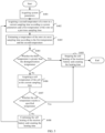
- Embodiment 1 of the present application provides a traction battery self-heating control method
- an executive body of the method is an MCU
- the method includes the following steps: S201, acquiring a second temperature of a rotor according to system parameters and a first temperature of a rotor of a permanent magnet motor.
- the system parameters include a material specific heat capacity of the rotor, a mass of the rotor and a power for heating the rotor in a sampling time interval.
- the first temperature is a temperature of the rotor at a first sampling time
- the second temperature is a temperature of the rotor at a second sampling time.
- the second sampling time is a current sampling time
- the first sampling time is a previous sampling time of the second sampling time.
- the third temperature is a temperature of the rotor at a third sampling time, and the third sampling time is a next sampling time of the second sampling time.
- the MCU generates a motor control instruction to stop heating, and stops heating the traction battery by controlling the inverter.
- the MCU generates the motor control instruction to continue heating, and makes the permanent magnet motor continue to heat the traction battery by controlling the inverter.
- the rotor temperature under the self-heating condition is first estimated, and then the rotor temperature is compared with the demagnetization temperature of the rotor to determine whether to stop the self-heating of the traction battery, so as to realize the control of the self-heating process of the traction battery.
- Embodiment 2 of the present application provides a traction battery self-heating control method
- an executive body of the method is an MCU
- the method includes the following steps: S301, acquiring a second temperature of a rotor according to system parameters and a first temperature of a rotor of a permanent magnet motor.
- the second temperature of the rotor is acquired by determining a rotor temperature change amount in a sampling time interval according to system parameters.
- a second temperature is determined according to the first temperature and the rotor temperature change amount.
- the first temperature and the rotor temperature change amount are superimposed to obtain the second temperature.
- the rotor temperature change amount in the sampling time interval is obtained according to the system parameters, and the rotor temperature in the current sampling time is obtained according to the rotor temperature in the previous sampling time and the calculated rotor temperature change amount, so as to realize the rotor temperature estimation under the self-heating working condition.
- the third temperature of the rotor is estimated by determining the rotor temperature change amount according to the first temperature and the second temperature, and estimating the third temperature according to the second temperature and the rotor temperature change amount.
- the second temperature is subtracted from the first temperature to determine the rotor temperature change amount over a sampling time interval. Then, the second temperature of the rotor at the current sampling time and the rotor temperature change amount in the sampling time interval are superimposed to determine the third temperature of the rotor at the next sampling time.
- the first temperature represents a temperature of the rotor at an initial sampling time
- an ambient temperature of the rotor is used as the temperature of the initial sampling time.
- the cell temperature of the cell of the traction battery at the second sampling time is collected by a sensor arranged inside the traction battery.
- S305 and 5306 are not limited to being placed after the step S304, that is, the steps of collecting the cell temperature, and judging the cell temperature are not limited to following the step of judging whether the rotor temperature reaches the demagnetization temperature, but may also be executed before any one of the steps S301 to S304.
- the specified temperature of the cell is determined according to the cell material. When the cell temperature of the traction battery reaches the specified temperature, the traction battery can achieve the best performance. Whether to stop the self-heating of the traction battery is determined according to the cell temperature, and the self-heating is stopped when the cell temperature reaches the specified temperature of the cell, and thus realizing the control of the self-heating process of the traction battery.
- the rotor temperature change amount in the sampling time interval is determined according to the system parameters.
- a second temperature is then determined according to the first temperature and the rotor temperature change amount.
- the third temperature of the rotor in the next sampling time can be further estimated. After the rotor temperature under the self-heating condition is estimated, whether to stop the self-heating of the traction battery is determined according to the rotor temperature and the rotor demagnetization temperature, and the self-heating control of the traction battery is realized.
- an executive body of the method is an MCU, and the method includes the following steps: S401. acquiring system parameters of a permanent magnet motor.
- the system parameters include a material specific heat capacity of the rotor, a mass of the rotor and a power for heating the rotor in a sampling time interval.
- the power ⁇ P 1 for heating the rotor in the sampling time interval is obtained by: determining a heating power of the permanent magnet motor according to a loss and a heat dissipation power P i of the permanent magnet motor; acquiring a heating power of a stator core and a heating power of a stator winding of the permanent magnet motor; and determining the power ⁇ P 1 for heating the rotor according to the heating power of the permanent magnet motor, the heating power of the stator winding and the heating power of the stator core.
- the loss of permanent magnet motor is calculated by: calculating the loss of the permanent magnet motor according to a stator core loss P Fe , a stator winding loss P Cu and an eddy current loss of the rotor P R .
- f is the electrification frequency of the stator winding
- B m is the amplitude of magnetic flux density of the stator core.
- the current I A , I B , I C in the stator winding can be obtained by MCU sampling.
- stator eddy current loss P R the stator core loss P Fe and stator winding loss P Cu are calculated respectively, and then the stator core loss P R , stator winding loss P Pe and rotor eddy current loss P Cu are superimposed to obtain the permanent magnet motor loss.
- the heat dissipation power P i of the permanent magnet motor is calculated according to the cooling structure of the motor.
- the heating power ⁇ P of the permanent magnet motor can be obtained by subtracting the loss and the heat dissipation power P i of the permanent magnet motor.
- the heating power of the stator core and the heating power of the stator winding of the permanent magnet motor by: acquiring a temperature change amount of the stator core and a temperature change amount of the stator winding in a sampling time interval are obtained; determining the heating power of the stator core ⁇ P 2 according to the temperature change amount of the stator core, a mass of the stator core M S and a material specific heat capacity of the stator core C S ; and determining the heating power of the stator winding ⁇ P 3 according to a temperature change amount of the stator winding, a mass of the stator winding M Cu and a material specific heat capacity of the stator winding C Cu .
- the heating power ⁇ P 1 of permanent magnet motor is subtracted from the heating power of stator winding and subtracted from the heating power of stator core, so as to obtain the heating power of rotor.
- the motor heating power is determined according to the motor loss and the motor heat dissipation power, and then the rotor heating power is calculated according to the motor heating power, the stator core heating power and the stator winding heating power, and then the rotor temperature can be further estimated according to the rotor heating power.
- T Ri ⁇ T R + T R i ⁇ 1
- T Ri denotes the temperature of the rotor at the current sampling time
- T Ri -1 denotes the temperature of the rotor at the previous sampling time.
- T Ri + 1 ⁇ ⁇ ⁇ t + T Ri
- T Ri +1 denotes a rotor temperature at the next sampling time.
- the rotor temperature can be further estimated based on the system parameters, and the rotor temperature under the self-heating working condition can be estimated by the above method.
- the rotor temperature is compared with the rotor demagnetization temperature, to determine whether to stop the self-heating of the traction battery according to the comparison result, thus realizing the control of the self-heating process of the traction battery.
- Embodiment 4 of the present application is described below to provide a traction battery self-heating control method, where an executive body of the method is an MCU, and the method includes the following steps: S501. acquiring system parameters of a permanent magnet motor.
- a current in the stator winding is collected by a current sensor arranged on the stator winding, a stator winding temperature T Cu and a stator core temperature T s are collected by a temperature sensor arranged on the stator winding and the stator core, and an ambient temperature is collected by a temperature sensor arranged in the environment.
- the data collected by each sensor are collected by the motor controller unit MCU, to obtain a stator winding current amplitude I 1 of the permanent magnet motor, a frequency f of the current supplied to the stator winding, the stator winding temperature T Cu of the permanent motor, the motor stator core temperature T s of the permanent motor and the ambient temperature T 0 , and the ambient temperature is used as the initial temperature of the rotor at the initial sampling time.
- stator flux density B m and rotor flux density B s corresponding to the stator winding supplied with different currents is established.
- Change amounts of the temperature of the stator core and the temperature of the stator winding are measured by the temperature sensors on the surface of the stator core and the end portion of the stator winding, and then the heating power of the stator winding and the heating power of the stator core are calculated.
- stator winding loss The current and frequency of stator winding are measured by a current sensor, and the stator winding loss is calculated.
- stator flux density and rotor flux density corresponding to heating current are determined by searching the flux density correspondence table, and the stator core loss and rotor eddy current loss are calculated.
- MCU After collecting the data of each sensor, MCU determines the stator magnetic flux density B m according to the current supplied to the stator winding, and then calculates the power for heating rotor heating in the sampling time interval according to formulae (1) to (8). MCU also needs to load the material specific heat capacity of the rotor and the mass of the rotor.
- a second temperature of the rotor at the current sampling time is calculated by formula (9).
- the temperature of the rotor at a next sampling time is predicted by formula (12).
- the heating of the traction battery is stopped, and the heating time of the traction battery is counted, and the method ends.
- the temperature sensor arranged in the traction battery collects the temperature of the cell, and the BMS collects the temperature of the cell obtained by the temperature sensor, through the communication between MCU and BMS, the BMS transmits the temperature of the cell to the motor controller unit MCU.
- data are collected by sensors arranged in the stator and the environment, based on the above data, the system parameters are determined, and then the rotor temperature is estimated according to the above system parameters. After obtaining the rotor temperature under the self-heating condition, the rotor temperature is compared with the rotor demagnetization temperature to determine whether to stop the self-heating of the traction battery and realize the control of the self-heating process of the traction battery.
- the present application provides a motor controller for executing various steps in the self-heating control method of the permanent magnet motor of the above embodiment
- the motor controller 600 includes: an acquisition module 601 for acquiring a second temperature of a rotor according to system parameters and a first temperature of a rotor of a permanent magnet motor, where the system parameters include a material specific heat capacity of the rotor, a mass of the rotor, and a power for heating the rotor in a sampling time interval, the first temperature is a temperature of the rotor at a first sampling time, the second temperature is a temperature of the rotor at a second sampling time, the second sampling time is a current sampling time, and the first sampling time is a previous sampling time of the second sampling time; an estimation module 602 for estimating a third temperature of the rotor according to the first temperature and the second temperature, where the third temperature is a temperature of the rotor at a third sampling time, and the third sampling time is a next sampling time of the second
- the motor controller also includes a collecting module 604; the collecting module 604 is used for collecting the cell temperature of the cell of the traction battery at the second sampling time; the control module 603 is also used for stopping the self-heating of the traction battery when the cell temperature reaches a specified temperature of the cell.
- the acquisition module 601 is specifically used for: determining a rotor temperature change amount in a sampling time interval according to the system parameters; and determining the second temperature according to the first temperature and the rotor temperature change amount.
- the estimation module 602 is specifically used for: determining the rotor temperature change amount according to the first temperature and the second temperature; and estimating the third temperature according to the second temperature and the rotor temperature change amount.
- the acquisition module 601 is also used for: determining a heating power of the permanent magnet motor according to a loss and a heat dissipation power of the permanent magnet motor; acquiring a heating power of a stator winding and a heating power of a stator winding of the permanent magnet motor; and determining the power for heating the rotor according to the heating power of the permanent magnet motor, the heating power of the stator winding and the heating power of the stator core.
- the acquisition module 601 is also used for: calculating the loss of the permanent magnet motor according to a stator core loss, a stator winding loss and an eddy current loss of the rotor.
- the acquisition module 601 is specifically used for: acquiring a temperature change amount of the stator core and a temperature change amount of the stator winding in a sampling time interval are obtained; determining the heating power of the stator core according to the temperature change amount of the stator core, a mass of the stator core and a material specific heat capacity of the stator core; and determining the heating power of the stator winding according to a temperature change amount of the stator winding, a mass of the stator winding and a material specific heat capacity of the stator winding.
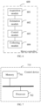
- a control device 700 provided in the embodiment includes a memory 701 and a processor 702.
- the memory 701 is used for storing computer-executed instructions; the processor 702, is used for executing computer-executed instructions stored in the memory, to implement the steps executed by the self-heating control method of the permanent magnet motor in the above-described embodiments.
- the processor 702 is used for executing computer-executed instructions stored in the memory, to implement the steps executed by the self-heating control method of the permanent magnet motor in the above-described embodiments.
- the processor 702 is used for executing computer-executed instructions stored in the memory, to implement the steps executed by the self-heating control method of the permanent magnet motor in the above-described embodiments.
- the memory 701 may be either independent or integrated with the processor 702.
- the control device also includes a bus for connecting the memory 701 and the processor 702 when the memory 701 is independently disposed.
- the embodiments of the application also provide a computer-readable storage medium in which the computer-executed instruction is stored.
- the processor executes the computer-executed instruction, the self-heating control method of the permanent magnet motor executed by the above control device is realized.
Landscapes
- Engineering & Computer Science (AREA)
- Manufacturing & Machinery (AREA)
- Chemical & Material Sciences (AREA)
- Chemical Kinetics & Catalysis (AREA)
- Electrochemistry (AREA)
- General Chemical & Material Sciences (AREA)
- Power Engineering (AREA)
- Physics & Mathematics (AREA)
- General Physics & Mathematics (AREA)
- Mechanical Engineering (AREA)
- Transportation (AREA)
- Sustainable Energy (AREA)
- Sustainable Development (AREA)
- Life Sciences & Earth Sciences (AREA)
- Automation & Control Theory (AREA)
- Secondary Cells (AREA)
- Electric Propulsion And Braking For Vehicles (AREA)
- Control Of Ac Motors In General (AREA)
- Charge And Discharge Circuits For Batteries Or The Like (AREA)
Claims (15)
- Procédé de commande de chauffage automatique de batterie de traction au moyen d'un moteur à aimants permanents, comprenant :l'acquisition (S201) d'une deuxième température du rotor du moteur à aimants permanents selon des paramètres du système et d'une première température du rotor du moteur à aimants permanents ; les paramètres du système comprenant : une capacité thermique massique du rotor, une masse du rotor et une puissance de chauffage du rotor dans un intervalle de temps d'échantillonnage, la première température étant une température du rotor à un premier instant d'échantillonnage, la deuxième température étant une température du rotor à un deuxième instant d'échantillonnage, le deuxième instant d'échantillonnage étant un instant d'échantillonnage courant, et le premier instant d'échantillonnage étant un instant d'échantillonnage antérieur au deuxième instant d'échantillonnage ;la prédiction (S202) d'une troisième température du rotor en fonction de la première température et de la deuxième température, la troisième température étant une température du rotor à un troisième instant d'échantillonnage, et le troisième instant d'échantillonnage étant un instant d'échantillonnage suivant du deuxième instant d'échantillonnage ; etl'arrêt (S204) du chauffage automatique de la batterie de traction lorsque la troisième température atteint une température de démagnétisation du rotor.
- Procédé selon la revendication 1, lequel procédé comprend en outre : la collecte de la température de cellule d'une cellule de la batterie de traction au deuxième instant d'échantillonnage ; et
l'arrêt du chauffage automatique de la batterie de traction lorsque la température de cellule atteint une température spécifiée de la cellule. - Procédé selon la revendication 1, dans lequel l'acquisition de la deuxième température du rotor en fonction des paramètres du système et de la première température du rotor comprend spécifiquement :la détermination d'une quantité de variation de température du rotor dans l'intervalle de temps d'échantillonnage en fonction des paramètres du système ; etla détermination de la deuxième température en fonction de la première température et de la quantité de variation de température du rotor.
- Procédé selon la revendication 3, dans lequel la détermination de la quantité de variation de température du rotor dans l'intervalle de temps d'échantillonnage en fonction des paramètres du système comprend spécifiquement :
la détermination de la quantité de variation de température du rotor en fonction d'une première formule, la première formule étant :
où ΔTR désigne la quantité de variation de température du rotor, Δτ désigne l'intervalle de temps d'échantillonnage, CR désigne la capacité thermique massique du rotor, MR désigne la masse du rotor, et ΔP 1 désigne la puissance de chauffage du rotor. - Procédé selon l'une quelconque des revendications 1 à 4, dans lequel l'estimation de la troisième température du rotor en fonction de la première température et de la deuxième température comprend spécifiquement :la détermination d'une quantité de variation de température du rotor en fonction de la première température et de la deuxième température ; etl'estimation de la troisième température en fonction de la deuxième température et de la quantité de variation de température du rotor.
- Procédé selon l'une quelconque des revendications 1 à 4, lequel procédé comprend en outre :la détermination d'une puissance de chauffage du moteur à aimants permanents en fonction d'une perte et d'une puissance de dissipation thermique du moteur à aimants permanents ;l'acquisition d'une puissance de chauffage d'un noyau de stator et d'une puissance de chauffage d'un enroulement de stator du moteur à aimants permanents ; etla détermination de la puissance de chauffage du rotor en fonction de la puissance de chauffage du moteur à aimants permanents, la puissance de chauffage de l'enroulement de stator et la puissance de chauffage du noyau de stator.
- Procédé selon la revendication 6, dans lequel, avant la détermination de la puissance de chauffage du moteur à aimants permanents en fonction d'une perte et d'une puissance de dissipation thermique du moteur à aimants permanents, le procédé comprend en outre
le calcul de la perte du moteur à aimants permanents en fonction d'une perte du noyau de stator, d'une perte de l'enroulement de stator et d'une perte par courants de Foucault du rotor. - Procédé selon la revendication 6, dans lequel l'acquisition de la puissance de chauffage du noyau de stator et de la puissance de chauffage de l'enroulement de stator du moteur à aimants permanents comprend spécifiquementl'acquisition d'une quantité de variation de température du noyau de stator et d'une quantité de variation de température de l'enroulement de stator dans l'intervalle de temps d'échantillonnage ;la détermination de la puissance de chauffage du noyau de stator en fonction de la quantité de variation de température du noyau de stator, d'une masse du noyau de stator et d'une capacité thermique massique du noyau de stator ; etla détermination de la puissance de chauffage de l'enroulement de stator en fonction de la quantité de variation de température de l'enroulement de stator, d'une masse de l'enroulement de stator et d'une capacité thermique massique de l'enroulement de stator.
- Procédé selon l'une quelconque des revendications 1 à 4, lequel procédé comprend en outre :
la détermination d'une perte par courants de Foucault du rotor en fonction d'une deuxième formule, la deuxième formule étant :
- Contrôleur de moteur à aimants permanents, comprenant :un module d'acquisition, configuré pour acquérir une deuxième température du rotor du moteur à aimants permanents en fonction des paramètres du système et d'une première température du rotor du moteur à aimants permanents ; les paramètres du système comprenant : une capacité thermique massique du rotor, une masse du rotor et une puissance de chauffage du rotor dans un intervalle de temps d'échantillonnage, la première température étant une température du rotor à un premier instant d'échantillonnage, la deuxième température étant une température du rotor à un deuxième instant d'échantillonnage, le deuxième instant d'échantillonnage étant un instant d'échantillonnage courant, et le premier instant d'échantillonnage étant un instant d'échantillonnage antérieur au deuxième instant d'échantillonnage ;un module de prédiction, configuré pour prédire une troisième température du rotor en fonction de la première température et de la deuxième température, la troisième température étant une température du rotor à un troisième instant d'échantillonnage, et le troisième instant d'échantillonnage étant un instant d'échantillonnage suivant du deuxième instant d'échantillonnage ; etun module de commande configuré pour arrêter le chauffage automatique d'une batterie de traction lorsque la troisième température atteint une température de démagnétisation du rotor.
- Contrôleur de moteur à aimants permanents selon la revendication 10, le contrôleur de moteur comprenant en outre un module collecteur ;le module collecteur étant configuré pour collecter une température de cellule d'une cellule de la batterie de traction au deuxième instant d'échantillonnage ; etle module de commande étant en outre configuré pour arrêter le chauffage automatique de la batterie de traction lorsque la température de cellule atteint une température spécifiée de la cellule.
- Contrôleur de moteur à aimants permanents selon la revendication 10, dans lequel le module d'acquisition est spécifiquement configuré pour :déterminer une quantité de variation de température du rotor dans l'intervalle de temps d'échantillonnage en fonction des paramètres du système ; etdéterminer la deuxième température en fonction de la première température et de la quantité de variation de température du rotor.
- Contrôleur de moteur à aimants permanents selon la revendication 12, dans lequel le module d'acquisition est spécifiquement configuré pour :
déterminer la quantité de variation de température du rotor en fonction d'une première formule, la première formule étant :
où ΔTR désigne la quantité de variation de température du rotor, Δτ désigne l'intervalle de temps d'échantillonnage, CR désigne la capacité thermique massique du rotor, MR désigne la masse du rotor, et ΔP 1 désigne la puissance de chauffage du rotor. - Contrôleur de moteur à aimants permanents selon l'une quelconque des revendications 10 à 13, dans lequel le module d'estimation est spécifiquement configuré pour :déterminer une quantité de variation de température du rotor en fonction de la première température et de la deuxième température ; etestimer la troisième température en fonction de la deuxième température et de la quantité de variation de température du rotor.
- Système d'alimentation comprenant : un moteur permanent, une batterie de traction, un inverseur, et le contrôleur de moteur à aimants permanents selon l'une quelconque des revendications 10 à 14.
Applications Claiming Priority (2)
| Application Number | Priority Date | Filing Date | Title |
|---|---|---|---|
| CN202010664362.6A CN113921951B (zh) | 2020-07-10 | 2020-07-10 | 动力电池自加热控制方法以及装置 |
| PCT/CN2021/093844 WO2022007501A1 (fr) | 2020-07-10 | 2021-05-14 | Procédé et appareil de commande d'autochauffage pour une batterie d'alimentation |
Publications (3)
| Publication Number | Publication Date |
|---|---|
| EP4009420A1 EP4009420A1 (fr) | 2022-06-08 |
| EP4009420A4 EP4009420A4 (fr) | 2022-11-30 |
| EP4009420B1 true EP4009420B1 (fr) | 2023-09-20 |
Family
ID=79232343
Family Applications (1)
| Application Number | Title | Priority Date | Filing Date |
|---|---|---|---|
| EP21838030.1A Active EP4009420B1 (fr) | 2020-07-10 | 2021-05-14 | Procédé et appareil de commande d'autochauffage pour une batterie d'alimentation |
Country Status (7)
| Country | Link |
|---|---|
| US (1) | US11605848B2 (fr) |
| EP (1) | EP4009420B1 (fr) |
| JP (1) | JP7259089B2 (fr) |
| KR (1) | KR102488463B1 (fr) |
| CN (1) | CN113921951B (fr) |
| HU (1) | HUE064588T2 (fr) |
| WO (1) | WO2022007501A1 (fr) |
Cited By (1)
| Publication number | Priority date | Publication date | Assignee | Title |
|---|---|---|---|---|
| DE102023132918A1 (de) * | 2023-10-11 | 2025-04-17 | GM Global Technology Operations LLC | Hochfrequenz-wechselstrom-batterieheizung mit spannungsbefehlen |
Families Citing this family (4)
| Publication number | Priority date | Publication date | Assignee | Title |
|---|---|---|---|---|
| CN115158100B (zh) * | 2022-06-29 | 2025-02-28 | 东风汽车集团股份有限公司 | 一种电池自加热系统的控制方法 |
| CN115284895A (zh) * | 2022-08-23 | 2022-11-04 | 中国第一汽车股份有限公司 | 燃料电池发动机的热管理系统、热管理方法以及车辆 |
| CN118763961B (zh) * | 2024-09-03 | 2025-01-21 | 深蓝汽车南京研究院有限公司 | 一种加热控制方法、装置、车载设备及车辆 |
| CN119253147A (zh) * | 2024-10-17 | 2025-01-03 | 东风汽车集团股份有限公司 | 基于电机绕组的电池包加热方法、装置、设备及存储介质 |
Family Cites Families (26)
| Publication number | Priority date | Publication date | Assignee | Title |
|---|---|---|---|---|
| JPS50154912A (fr) * | 1974-06-03 | 1975-12-13 | ||
| JPH1127806A (ja) * | 1997-07-03 | 1999-01-29 | Nissan Motor Co Ltd | ハイブリッド自動車の制御装置 |
| DE602006012350D1 (de) * | 2005-11-09 | 2010-04-01 | Toyota Motor Co Ltd | Batteriezustand-diagnosevorrichtung |
| JP4572907B2 (ja) | 2007-03-29 | 2010-11-04 | トヨタ自動車株式会社 | モータ制御装置、制御方法及び制御プログラム |
| US8482238B2 (en) * | 2010-11-30 | 2013-07-09 | Caterpillar Inc. | System and method for estimating a generator rotor temperature in an electric drive machine |
| JP5259752B2 (ja) * | 2011-02-04 | 2013-08-07 | 株式会社日立製作所 | 車両走行用モータの制御装置及びそれを搭載した車両 |
| DE102011121272A1 (de) * | 2011-12-15 | 2013-06-20 | Audi Ag | Verfahren und Vorrichtung zur temperaturabhängigen Steuerung eines Elektromotors |
| AR093690A1 (es) * | 2012-11-30 | 2015-06-17 | Basf Se | Unidad de almacenamiento para un dispositivo de impulsion en un vehiculo |
| KR101394548B1 (ko) * | 2013-02-27 | 2014-05-14 | 창원대학교 산학협력단 | 전자기기의 열 해석방법 |
| US8983746B1 (en) * | 2013-10-11 | 2015-03-17 | GM Global Technology Operations LLC | Method for determining dry dual clutch transmission temperatures following offline periods |
| CN105762434B (zh) * | 2016-05-16 | 2018-12-07 | 北京理工大学 | 一种具有自加热功能的电源系统和车辆 |
| CN105932363B (zh) * | 2016-05-16 | 2019-03-19 | 北京理工大学 | 一种电源系统的自加热方法 |
| CN108306078A (zh) * | 2018-03-07 | 2018-07-20 | 苏州汇川联合动力系统有限公司 | 动力电池加热系统及方法 |
| JP2019170004A (ja) * | 2018-03-22 | 2019-10-03 | 本田技研工業株式会社 | 回転電機ユニット、車両及び回転電機ユニットの制御方法 |
| KR102570296B1 (ko) * | 2018-11-08 | 2023-08-24 | 현대자동차주식회사 | 차량 및 그 제어방법 |
| CN111355000B (zh) * | 2018-12-21 | 2021-11-12 | 比亚迪股份有限公司 | 一种车辆及其动力电池加热装置与方法 |
| CN111347935B (zh) * | 2018-12-21 | 2021-10-22 | 比亚迪股份有限公司 | 一种车辆及其动力电池加热装置与方法 |
| CN110011586A (zh) * | 2019-03-25 | 2019-07-12 | 深圳市汇川技术股份有限公司 | 永磁同步电机退磁保护方法、系统、装置及存储介质 |
| CN109823234B (zh) * | 2019-04-23 | 2019-07-16 | 上海汽车集团股份有限公司 | 一种驱动系统的控制方法、驱动系统及新能源汽车 |
| CN110138312A (zh) * | 2019-05-13 | 2019-08-16 | 浙江吉利控股集团有限公司 | 一种电机转子温度估计方法、装置及控制器 |
| CN110071682A (zh) * | 2019-06-13 | 2019-07-30 | 北斗航天汽车(北京)有限公司 | 电动电动车用驱动系统的自保护装置、自保护方法 |
| CN110323994B (zh) * | 2019-07-24 | 2021-02-26 | 重庆长安新能源汽车科技有限公司 | 实时在线估算电机转子温度的方法、系统、车辆及存储介质 |
| CN110702272B (zh) * | 2019-09-24 | 2021-11-05 | 中国第一汽车股份有限公司 | 一种电机转子温度的估算方法、装置、电机和存储介质 |
| CN111048856B (zh) * | 2019-12-17 | 2021-06-01 | 北京理工大学 | 一种动力电池极速自加热方法和装置 |
| CN111162351B (zh) * | 2019-12-30 | 2021-06-22 | 浙江吉智新能源汽车科技有限公司 | 一种动力电池自加热方法及其系统及汽车 |
| KR102805088B1 (ko) * | 2020-08-18 | 2025-05-09 | 현대자동차주식회사 | 차량용 전동식 오일 펌프의 제어방법 |
-
2020
- 2020-07-10 CN CN202010664362.6A patent/CN113921951B/zh active Active
-
2021
- 2021-05-14 EP EP21838030.1A patent/EP4009420B1/fr active Active
- 2021-05-14 KR KR1020217039640A patent/KR102488463B1/ko active Active
- 2021-05-14 HU HUE21838030A patent/HUE064588T2/hu unknown
- 2021-05-14 WO PCT/CN2021/093844 patent/WO2022007501A1/fr not_active Ceased
- 2021-05-14 JP JP2021571441A patent/JP7259089B2/ja active Active
-
2022
- 2022-07-29 US US17/877,208 patent/US11605848B2/en active Active
Cited By (1)
| Publication number | Priority date | Publication date | Assignee | Title |
|---|---|---|---|---|
| DE102023132918A1 (de) * | 2023-10-11 | 2025-04-17 | GM Global Technology Operations LLC | Hochfrequenz-wechselstrom-batterieheizung mit spannungsbefehlen |
Also Published As
| Publication number | Publication date |
|---|---|
| HUE064588T2 (hu) | 2024-03-28 |
| US20220376320A1 (en) | 2022-11-24 |
| US11605848B2 (en) | 2023-03-14 |
| CN113921951B (zh) | 2023-06-16 |
| WO2022007501A1 (fr) | 2022-01-13 |
| EP4009420A1 (fr) | 2022-06-08 |
| EP4009420A4 (fr) | 2022-11-30 |
| KR102488463B1 (ko) | 2023-01-12 |
| KR20220007729A (ko) | 2022-01-18 |
| JP7259089B2 (ja) | 2023-04-17 |
| JP2022539959A (ja) | 2022-09-14 |
| CN113921951A (zh) | 2022-01-11 |
Similar Documents
| Publication | Publication Date | Title |
|---|---|---|
| EP4009420B1 (fr) | Procédé et appareil de commande d'autochauffage pour une batterie d'alimentation | |
| CN111211719B (zh) | 一种永磁同步电机转子磁钢温度估算方法及系统 | |
| EP4116793A1 (fr) | Groupe motopropulseur, procédé d'estimation du débit du liquide de refroidissement et véhicule électrique | |
| US9415700B2 (en) | Battery thermal system and diagnostic method | |
| US20230062270A1 (en) | Method for heating a battery pack, battery heating system and electric apparatus | |
| US9267996B2 (en) | Method and system for estimating voltage of a battery element | |
| US9160272B2 (en) | Control device and control method for permanent magnet motor | |
| EP3442074A2 (fr) | Dispositif de refroidissement pour véhicule et procédé de commande pour véhicule | |
| US10819218B2 (en) | Power converter for electric vehicle | |
| CN105048021A (zh) | 电池温度估计系统 | |
| US9213068B2 (en) | Method and system for determining a battery element voltage | |
| EP4033587B1 (fr) | Module de modulation de courant, module de détermination de paramètre, système de chauffage de batterie, ainsi que procédé de commande et appareil de commande de ceux-ci | |
| US12249945B2 (en) | Control method, device, power system and electric vehicle | |
| US20200259354A1 (en) | Charging and discharging control device for battery pack and charging and discharging control method for battery pack | |
| JPH10108301A (ja) | 電気自動車の走行可能距離算出方法 | |
| JP2013096785A (ja) | 電池劣化判定装置および電池劣化判定方法 | |
| CN114725576B (zh) | 一种电池装置、其加热方法及用电设备 | |
| RU79840U1 (ru) | Устройство для мониторинга теплового состояния тягового двигателя | |
| JP6119647B2 (ja) | 電動車両 | |
| US12139042B2 (en) | Vehicle control based on battery temperature estimation | |
| CN114734820A (zh) | 转子温度估算方法、电动车辆及可读存储介质 | |
| CN116238306B (zh) | 多合一动力系统和其温度估算方法 | |
| JPH07140216A (ja) | 電気自動車用走行可能時間表示装置 | |
| CN114189186A (zh) | 永磁同步电机的永磁体温度估算方法及装置 | |
| Lin et al. | A Review of Cooling Systems in Electric/Hybrid Vehicles |
Legal Events
| Date | Code | Title | Description |
|---|---|---|---|
| STAA | Information on the status of an ep patent application or granted ep patent |
Free format text: STATUS: THE INTERNATIONAL PUBLICATION HAS BEEN MADE |
|
| PUAI | Public reference made under article 153(3) epc to a published international application that has entered the european phase |
Free format text: ORIGINAL CODE: 0009012 |
|
| STAA | Information on the status of an ep patent application or granted ep patent |
Free format text: STATUS: REQUEST FOR EXAMINATION WAS MADE |
|
| 17P | Request for examination filed |
Effective date: 20220304 |
|
| AK | Designated contracting states |
Kind code of ref document: A1 Designated state(s): AL AT BE BG CH CY CZ DE DK EE ES FI FR GB GR HR HU IE IS IT LI LT LU LV MC MK MT NL NO PL PT RO RS SE SI SK SM TR |
|
| A4 | Supplementary search report drawn up and despatched |
Effective date: 20221102 |
|
| RIC1 | Information provided on ipc code assigned before grant |
Ipc: H02P 29/66 20160101ALI20221026BHEP Ipc: B60L 58/25 20190101ALI20221026BHEP Ipc: B60L 58/27 20190101ALI20221026BHEP Ipc: H02P 23/14 20060101ALI20221026BHEP Ipc: H01M 10/637 20140101ALI20221026BHEP Ipc: H01M 10/625 20140101ALI20221026BHEP Ipc: H01M 10/615 20140101AFI20221026BHEP |
|
| GRAP | Despatch of communication of intention to grant a patent |
Free format text: ORIGINAL CODE: EPIDOSNIGR1 |
|
| STAA | Information on the status of an ep patent application or granted ep patent |
Free format text: STATUS: GRANT OF PATENT IS INTENDED |
|
| DAV | Request for validation of the european patent (deleted) | ||
| DAX | Request for extension of the european patent (deleted) | ||
| INTG | Intention to grant announced |
Effective date: 20230622 |
|
| GRAS | Grant fee paid |
Free format text: ORIGINAL CODE: EPIDOSNIGR3 |
|
| GRAA | (expected) grant |
Free format text: ORIGINAL CODE: 0009210 |
|
| STAA | Information on the status of an ep patent application or granted ep patent |
Free format text: STATUS: THE PATENT HAS BEEN GRANTED |
|
| RAP3 | Party data changed (applicant data changed or rights of an application transferred) |
Owner name: CONTEMPORARY AMPEREX TECHNOLOGY CO., LIMITED |
|
| AK | Designated contracting states |
Kind code of ref document: B1 Designated state(s): AL AT BE BG CH CY CZ DE DK EE ES FI FR GB GR HR HU IE IS IT LI LT LU LV MC MK MT NL NO PL PT RO RS SE SI SK SM TR |
|
| REG | Reference to a national code |
Ref country code: GB Ref legal event code: FG4D |
|
| REG | Reference to a national code |
Ref country code: CH Ref legal event code: EP |
|
| REG | Reference to a national code |
Ref country code: IE Ref legal event code: FG4D |
|
| REG | Reference to a national code |
Ref country code: DE Ref legal event code: R096 Ref document number: 602021005316 Country of ref document: DE |
|
| P01 | Opt-out of the competence of the unified patent court (upc) registered |
Effective date: 20230908 |
|
| REG | Reference to a national code |
Ref country code: LT Ref legal event code: MG9D |
|
| PG25 | Lapsed in a contracting state [announced via postgrant information from national office to epo] |
Ref country code: GR Free format text: LAPSE BECAUSE OF FAILURE TO SUBMIT A TRANSLATION OF THE DESCRIPTION OR TO PAY THE FEE WITHIN THE PRESCRIBED TIME-LIMIT Effective date: 20231221 |
|
| REG | Reference to a national code |
Ref country code: NL Ref legal event code: MP Effective date: 20230920 |
|
| PG25 | Lapsed in a contracting state [announced via postgrant information from national office to epo] |
Ref country code: SE Free format text: LAPSE BECAUSE OF FAILURE TO SUBMIT A TRANSLATION OF THE DESCRIPTION OR TO PAY THE FEE WITHIN THE PRESCRIBED TIME-LIMIT Effective date: 20230920 Ref country code: RS Free format text: LAPSE BECAUSE OF FAILURE TO SUBMIT A TRANSLATION OF THE DESCRIPTION OR TO PAY THE FEE WITHIN THE PRESCRIBED TIME-LIMIT Effective date: 20230920 Ref country code: NO Free format text: LAPSE BECAUSE OF FAILURE TO SUBMIT A TRANSLATION OF THE DESCRIPTION OR TO PAY THE FEE WITHIN THE PRESCRIBED TIME-LIMIT Effective date: 20231220 Ref country code: LV Free format text: LAPSE BECAUSE OF FAILURE TO SUBMIT A TRANSLATION OF THE DESCRIPTION OR TO PAY THE FEE WITHIN THE PRESCRIBED TIME-LIMIT Effective date: 20230920 Ref country code: LT Free format text: LAPSE BECAUSE OF FAILURE TO SUBMIT A TRANSLATION OF THE DESCRIPTION OR TO PAY THE FEE WITHIN THE PRESCRIBED TIME-LIMIT Effective date: 20230920 Ref country code: HR Free format text: LAPSE BECAUSE OF FAILURE TO SUBMIT A TRANSLATION OF THE DESCRIPTION OR TO PAY THE FEE WITHIN THE PRESCRIBED TIME-LIMIT Effective date: 20230920 Ref country code: GR Free format text: LAPSE BECAUSE OF FAILURE TO SUBMIT A TRANSLATION OF THE DESCRIPTION OR TO PAY THE FEE WITHIN THE PRESCRIBED TIME-LIMIT Effective date: 20231221 Ref country code: FI Free format text: LAPSE BECAUSE OF FAILURE TO SUBMIT A TRANSLATION OF THE DESCRIPTION OR TO PAY THE FEE WITHIN THE PRESCRIBED TIME-LIMIT Effective date: 20230920 |
|
| REG | Reference to a national code |
Ref country code: AT Ref legal event code: MK05 Ref document number: 1614129 Country of ref document: AT Kind code of ref document: T Effective date: 20230920 |
|
| PG25 | Lapsed in a contracting state [announced via postgrant information from national office to epo] |
Ref country code: NL Free format text: LAPSE BECAUSE OF FAILURE TO SUBMIT A TRANSLATION OF THE DESCRIPTION OR TO PAY THE FEE WITHIN THE PRESCRIBED TIME-LIMIT Effective date: 20230920 |
|
| REG | Reference to a national code |
Ref country code: HU Ref legal event code: AG4A Ref document number: E064588 Country of ref document: HU |
|
| PG25 | Lapsed in a contracting state [announced via postgrant information from national office to epo] |
Ref country code: IS Free format text: LAPSE BECAUSE OF FAILURE TO SUBMIT A TRANSLATION OF THE DESCRIPTION OR TO PAY THE FEE WITHIN THE PRESCRIBED TIME-LIMIT Effective date: 20240120 |
|
| PG25 | Lapsed in a contracting state [announced via postgrant information from national office to epo] |
Ref country code: AT Free format text: LAPSE BECAUSE OF FAILURE TO SUBMIT A TRANSLATION OF THE DESCRIPTION OR TO PAY THE FEE WITHIN THE PRESCRIBED TIME-LIMIT Effective date: 20230920 |
|
| PG25 | Lapsed in a contracting state [announced via postgrant information from national office to epo] |
Ref country code: ES Free format text: LAPSE BECAUSE OF FAILURE TO SUBMIT A TRANSLATION OF THE DESCRIPTION OR TO PAY THE FEE WITHIN THE PRESCRIBED TIME-LIMIT Effective date: 20230920 |
|
| PG25 | Lapsed in a contracting state [announced via postgrant information from national office to epo] |
Ref country code: SM Free format text: LAPSE BECAUSE OF FAILURE TO SUBMIT A TRANSLATION OF THE DESCRIPTION OR TO PAY THE FEE WITHIN THE PRESCRIBED TIME-LIMIT Effective date: 20230920 Ref country code: RO Free format text: LAPSE BECAUSE OF FAILURE TO SUBMIT A TRANSLATION OF THE DESCRIPTION OR TO PAY THE FEE WITHIN THE PRESCRIBED TIME-LIMIT Effective date: 20230920 Ref country code: IS Free format text: LAPSE BECAUSE OF FAILURE TO SUBMIT A TRANSLATION OF THE DESCRIPTION OR TO PAY THE FEE WITHIN THE PRESCRIBED TIME-LIMIT Effective date: 20240120 Ref country code: ES Free format text: LAPSE BECAUSE OF FAILURE TO SUBMIT A TRANSLATION OF THE DESCRIPTION OR TO PAY THE FEE WITHIN THE PRESCRIBED TIME-LIMIT Effective date: 20230920 Ref country code: EE Free format text: LAPSE BECAUSE OF FAILURE TO SUBMIT A TRANSLATION OF THE DESCRIPTION OR TO PAY THE FEE WITHIN THE PRESCRIBED TIME-LIMIT Effective date: 20230920 Ref country code: CZ Free format text: LAPSE BECAUSE OF FAILURE TO SUBMIT A TRANSLATION OF THE DESCRIPTION OR TO PAY THE FEE WITHIN THE PRESCRIBED TIME-LIMIT Effective date: 20230920 Ref country code: AT Free format text: LAPSE BECAUSE OF FAILURE TO SUBMIT A TRANSLATION OF THE DESCRIPTION OR TO PAY THE FEE WITHIN THE PRESCRIBED TIME-LIMIT Effective date: 20230920 Ref country code: SK Free format text: LAPSE BECAUSE OF FAILURE TO SUBMIT A TRANSLATION OF THE DESCRIPTION OR TO PAY THE FEE WITHIN THE PRESCRIBED TIME-LIMIT Effective date: 20230920 Ref country code: PT Free format text: LAPSE BECAUSE OF FAILURE TO SUBMIT A TRANSLATION OF THE DESCRIPTION OR TO PAY THE FEE WITHIN THE PRESCRIBED TIME-LIMIT Effective date: 20240122 |
|
| PG25 | Lapsed in a contracting state [announced via postgrant information from national office to epo] |
Ref country code: PL Free format text: LAPSE BECAUSE OF FAILURE TO SUBMIT A TRANSLATION OF THE DESCRIPTION OR TO PAY THE FEE WITHIN THE PRESCRIBED TIME-LIMIT Effective date: 20230920 |
|
| REG | Reference to a national code |
Ref country code: DE Ref legal event code: R097 Ref document number: 602021005316 Country of ref document: DE |
|
| PG25 | Lapsed in a contracting state [announced via postgrant information from national office to epo] |
Ref country code: DK Free format text: LAPSE BECAUSE OF FAILURE TO SUBMIT A TRANSLATION OF THE DESCRIPTION OR TO PAY THE FEE WITHIN THE PRESCRIBED TIME-LIMIT Effective date: 20230920 |
|
| PLBE | No opposition filed within time limit |
Free format text: ORIGINAL CODE: 0009261 |
|
| STAA | Information on the status of an ep patent application or granted ep patent |
Free format text: STATUS: NO OPPOSITION FILED WITHIN TIME LIMIT |
|
| PG25 | Lapsed in a contracting state [announced via postgrant information from national office to epo] |
Ref country code: DK Free format text: LAPSE BECAUSE OF FAILURE TO SUBMIT A TRANSLATION OF THE DESCRIPTION OR TO PAY THE FEE WITHIN THE PRESCRIBED TIME-LIMIT Effective date: 20230920 |
|
| REG | Reference to a national code |
Ref country code: DE Ref legal event code: R081 Ref document number: 602021005316 Country of ref document: DE Owner name: CONTEMPORARY AMPEREX TECHNOLOGY (HONG KONG) LI, HK Free format text: FORMER OWNER: CONTEMPORARY AMPEREX TECHNOLOGY CO., LIMITED, NINGDE, FUJIAN, CN |
|
| 26N | No opposition filed |
Effective date: 20240621 |
|
| REG | Reference to a national code |
Ref country code: GB Ref legal event code: 732E Free format text: REGISTERED BETWEEN 20240829 AND 20240904 |
|
| REG | Reference to a national code |
Ref country code: HU Ref legal event code: GB9C Owner name: CONTEMPORARY AMPEREX TECHNOLOGY (HONG KONG) LIMITED, HK Free format text: FORMER OWNER(S): CONTEMPORARY AMPEREX TECHNOLOGY CO., LIMITED, CN Ref country code: HU Ref legal event code: FH1C Free format text: FORMER REPRESENTATIVE(S): DANUBIA SZABADALMI ES JOGI IRODA KFT., HU Representative=s name: DANUBIA SZABADALMI ES JOGI IRODA KFT., HU |
|
| PG25 | Lapsed in a contracting state [announced via postgrant information from national office to epo] |
Ref country code: SI Free format text: LAPSE BECAUSE OF FAILURE TO SUBMIT A TRANSLATION OF THE DESCRIPTION OR TO PAY THE FEE WITHIN THE PRESCRIBED TIME-LIMIT Effective date: 20230920 |
|
| PG25 | Lapsed in a contracting state [announced via postgrant information from national office to epo] |
Ref country code: SI Free format text: LAPSE BECAUSE OF FAILURE TO SUBMIT A TRANSLATION OF THE DESCRIPTION OR TO PAY THE FEE WITHIN THE PRESCRIBED TIME-LIMIT Effective date: 20230920 |
|
| PG25 | Lapsed in a contracting state [announced via postgrant information from national office to epo] |
Ref country code: BG Free format text: LAPSE BECAUSE OF FAILURE TO SUBMIT A TRANSLATION OF THE DESCRIPTION OR TO PAY THE FEE WITHIN THE PRESCRIBED TIME-LIMIT Effective date: 20230920 |
|
| PG25 | Lapsed in a contracting state [announced via postgrant information from national office to epo] |
Ref country code: BG Free format text: LAPSE BECAUSE OF FAILURE TO SUBMIT A TRANSLATION OF THE DESCRIPTION OR TO PAY THE FEE WITHIN THE PRESCRIBED TIME-LIMIT Effective date: 20230920 |
|
| REG | Reference to a national code |
Ref country code: CH Ref legal event code: PL |
|
| PG25 | Lapsed in a contracting state [announced via postgrant information from national office to epo] |
Ref country code: MC Free format text: LAPSE BECAUSE OF FAILURE TO SUBMIT A TRANSLATION OF THE DESCRIPTION OR TO PAY THE FEE WITHIN THE PRESCRIBED TIME-LIMIT Effective date: 20230920 |
|
| PG25 | Lapsed in a contracting state [announced via postgrant information from national office to epo] |
Ref country code: LU Free format text: LAPSE BECAUSE OF NON-PAYMENT OF DUE FEES Effective date: 20240514 |
|
| PG25 | Lapsed in a contracting state [announced via postgrant information from national office to epo] |
Ref country code: MC Free format text: LAPSE BECAUSE OF FAILURE TO SUBMIT A TRANSLATION OF THE DESCRIPTION OR TO PAY THE FEE WITHIN THE PRESCRIBED TIME-LIMIT Effective date: 20230920 Ref country code: LU Free format text: LAPSE BECAUSE OF NON-PAYMENT OF DUE FEES Effective date: 20240514 Ref country code: CH Free format text: LAPSE BECAUSE OF NON-PAYMENT OF DUE FEES Effective date: 20240531 |
|
| REG | Reference to a national code |
Ref country code: BE Ref legal event code: MM Effective date: 20240531 |
|
| PG25 | Lapsed in a contracting state [announced via postgrant information from national office to epo] |
Ref country code: IE Free format text: LAPSE BECAUSE OF NON-PAYMENT OF DUE FEES Effective date: 20240514 |
|
| PG25 | Lapsed in a contracting state [announced via postgrant information from national office to epo] |
Ref country code: BE Free format text: LAPSE BECAUSE OF NON-PAYMENT OF DUE FEES Effective date: 20240531 |
|
| PGFP | Annual fee paid to national office [announced via postgrant information from national office to epo] |
Ref country code: DE Payment date: 20250516 Year of fee payment: 5 |
|
| PGFP | Annual fee paid to national office [announced via postgrant information from national office to epo] |
Ref country code: HU Payment date: 20250430 Year of fee payment: 5 |
|
| PGFP | Annual fee paid to national office [announced via postgrant information from national office to epo] |
Ref country code: IT Payment date: 20250519 Year of fee payment: 5 |
|
| PGFP | Annual fee paid to national office [announced via postgrant information from national office to epo] |
Ref country code: FR Payment date: 20250519 Year of fee payment: 5 |
|
| PG25 | Lapsed in a contracting state [announced via postgrant information from national office to epo] |
Ref country code: CY Free format text: LAPSE BECAUSE OF FAILURE TO SUBMIT A TRANSLATION OF THE DESCRIPTION OR TO PAY THE FEE WITHIN THE PRESCRIBED TIME-LIMIT; INVALID AB INITIO Effective date: 20210514 |
|
| PGFP | Annual fee paid to national office [announced via postgrant information from national office to epo] |
Ref country code: GB Payment date: 20260331 Year of fee payment: 6 |