EP4009527A1 - Unité de commande pour un appareil électroménager - Google Patents
Unité de commande pour un appareil électroménager Download PDFInfo
- Publication number
- EP4009527A1 EP4009527A1 EP21209808.1A EP21209808A EP4009527A1 EP 4009527 A1 EP4009527 A1 EP 4009527A1 EP 21209808 A EP21209808 A EP 21209808A EP 4009527 A1 EP4009527 A1 EP 4009527A1
- Authority
- EP
- European Patent Office
- Prior art keywords
- unit
- layer
- character
- touch
- light
- Prior art date
- Legal status (The legal status is an assumption and is not a legal conclusion. Google has not performed a legal analysis and makes no representation as to the accuracy of the status listed.)
- Granted
Links
Images


Classifications
-
- H—ELECTRICITY
- H03—ELECTRONIC CIRCUITRY
- H03K—PULSE TECHNIQUE
- H03K17/00—Electronic switching or gating, i.e. not by contact-making and –breaking
- H03K17/94—Electronic switching or gating, i.e. not by contact-making and –breaking characterised by the way in which the control signals are generated
- H03K17/96—Touch switches
- H03K17/962—Capacitive touch switches
- H03K17/9622—Capacitive touch switches using a plurality of detectors, e.g. keyboard
-
- G—PHYSICS
- G09—EDUCATION; CRYPTOGRAPHY; DISPLAY; ADVERTISING; SEALS
- G09F—DISPLAYING; ADVERTISING; SIGNS; LABELS OR NAME-PLATES; SEALS
- G09F13/00—Illuminated signs; Luminous advertising
- G09F13/04—Signs, boards or panels, illuminated from behind the insignia
- G09F13/06—Signs, boards or panels, illuminated from behind the insignia using individual cut-out symbols or cut-out silhouettes, e.g. perforated signs
-
- H—ELECTRICITY
- H03—ELECTRONIC CIRCUITRY
- H03K—PULSE TECHNIQUE
- H03K2217/00—Indexing scheme related to electronic switching or gating, i.e. not by contact-making or -breaking covered by H03K17/00
- H03K2217/94—Indexing scheme related to electronic switching or gating, i.e. not by contact-making or -breaking covered by H03K17/00 characterised by the way in which the control signal is generated
- H03K2217/96—Touch switches
- H03K2217/9607—Capacitive touch switches
- H03K2217/960785—Capacitive touch switches with illumination
Definitions
- the invention relates to a control unit for a household appliance with a touch-sensitive unit and an LED unit positioned on the rear of this, the touch-sensitive unit being formed with a diffuser film whose upper side facing an operator has at least one character layer and whose underside facing away from this has at least one functional layer.
- a large number of operating units for household appliances are known from the prior art.
- a household appliance is operated using pushbuttons or rotary switches, the position of which can be seen using markings on a panel.
- the use of non-illuminated membrane keys, for example on microwaves, is known.
- touch-sensitive sensor keys grouped around a small LCD display are known, the current function of which is displayed to a user with a symbol.
- touch-sensitive screens with a backlight so-called “touch screens”
- touchscreens are now also widely used in household appliances, which enable the user to have a particularly comfortable operating experience.
- touchscreens are particularly easy to clean due to their continuous, smooth surface and are more hygienic than conventional control elements.
- the disadvantage is that the operating symbols for backlit touchscreens can only be adapted to other requirements or device variations in series production with a comparatively high level of effort.
- the at least one character layer has at least one character produced by means of laser radiation, which is at least partially transparent to light from the LED unit, the character layer outside the at least one character being exposed to light from the LED unit is impervious.
- the characters within the character layer are completely independent and can therefore be produced after the completion of the manufacturing process of the touch-sensitive unit and the associated lighting unit and the connection to the complete operating unit.
- the characters can be realized, for example, in an ablation process by means of laser radiation of an opaque layer, coating, film or the like previously applied to the diffuser film.
- a deep laser engraving of the opaque layer or the cutting out of the desired character contour by means of laser radiation from the opaque layer is possible.
- the at least one functional layer which contains the conductor tracks, the capacitive touch electrodes and an electrical interface, can be produced, for example, by cutting out a corresponding conductor track route from a laminated copper foil using laser radiation of a suitable wavelength and intensity or power.
- the functional layer with the trace routing required for the touch functionality can be formed using a conventional screen printing process.
- the functional layer is preferably printed onto the side of the diffuser film that is remote from the user.
- the functional layer can also be implemented with a touch-sensitive film designed as a separate component. This touch-sensitive foil can be connected in a suitable manner to the side of the diffuser foil facing away from the user, for example glued or welded.
- the production of the characters within the character layer by means of laser radiation allows a particularly high degree of contour definition and dimensional accuracy of the characters with practically any variability at the same time.
- the laser radiation can be generated with a gas or solid-state laser with sufficiently high power at a wavelength suitable for cutting and deep engraving.
- LED light emitting diode
- LED is used synonymously for “light emitting diode” in the context of the present description.
- a printed circuit board of the LED unit preferably has at least one light-emitting diode for the preferably selective backlighting of at least one assigned character of the character layer. Due to the backlighting of the characters in the character layer, they are particularly easy to read. If necessary, by activating certain LEDs of the LED unit, the associated characters can be made to light up or flash periodically, for example in order to transmit specific operating instructions to an operator of the household appliance.
- the printed circuit board of the LED unit has at least one numeric and/or alphanumeric display for preferably selective backlighting of an associated character on the character layer.
- the at least one display can be embodied in the form of an LED 7-segment display, an LED 5 ⁇ 7 dot matrix display, etc., for example.
- the at least one functional layer preferably has a large number of capacitive touch electrodes which are designed to generate an analyzable electrical signal in the event of a spatial proximity of an operator finger, which can be derived by means of a first electrical interface of the at least one functional layer.
- the printed circuit board of the LED unit has a second electrical interface, which is connected to the first electrical interface of the touch-sensitive unit and/or to at least one electronic control unit assigned to the printed circuit board and/or an electronic control and/or regulation unit of the Household appliance is connected. This allows the control unit to be electrically integrated into the household appliance without any problems.
- the electronic control unit is preferably designed at least to evaluate the electrical signals of the capacitive touch electrodes. As a result, the comparatively weak capacitive signals of the touch electrodes can be amplified and the touch-sensitive keys formed with the touch electrodes can be reliably selected.
- the at least one functional layer is provided with a protective layer on the underside, which in turn is provided with an adhesive layer at least in certain areas on the underside. Because of the adhesive layer, there is a robust and easy-to-produce mechanical connection between the touch-sensitive unit and the LED unit to create the operating unit.
- the adhesive layer has a non-adhesive peel-off layer on the underside.
- each light emitting diode and each numeric or alphanumeric display of the LED unit is associated with a light well as part of a light guide.
- the light wells can have an inner surface that is at least partially mirrored.
- the light guide has an opaque blocking layer outside the light wells facing the touch-sensitive unit.
- the blocking layer is arranged on the upper side of the light guide under a mask-like recess or omission of the light shafts and can be formed, for example, with a thin black film that is glued on.
- the character layer has a translucent cover. This avoids damage to the character layer due to external mechanical influences during operation of the household appliance.
- the touch-sensitive unit preferably has a 2D sensor, creating a touch-sensitive area such that the at least one character of the character layer can be formed largely freely within the touch-sensitive area.
- the at least one functional layer can have a large number of capacitively acting touch electrodes, which can be arranged, for example, in the form of a regular, sufficiently fine orthogonal and two-dimensional point grid.
- the figure 1 shows a highly schematic cross section of an operating unit according to the invention in a partially assembled state.
- the control unit 100 for a household appliance includes, among other things, a touch-sensitive unit 106 and an LED unit 112 positioned on the rear of this
- the upper side 122 of the diffuser film 116 has at least one character layer 130 which is formed at least in regions and faces an eye 124 of a human operator (not shown) of the household appliance.
- An electrical functional layer 148 is formed on the underside 142 of the diffuser film 116 .
- the at least one character layer 130 has two characters 154, 156 produced by means of laser radiation, which is not shown here, merely as an example.
- the characters 154, 156 of the character layer 130 are each at least partially transparent to visible light 164, 166 emitted by two light-emitting diodes 160, 162 of the LED unit 112, just as an example.
- the characters 154, 156 penetrate the character layer 130 completely.
- the character layer 130 is designed to be essentially opaque in the manner of a mask or masking.
- the characters 154, 156 can be realized, for example, by ablation by laser radiation of an opaque layer or film previously applied to the diffuser film as a character layer 130.
- a deep laser engraving of the opaque layer serving as the character layer 130 or the complete cutting out of the character contour from the character layer 130 with the aid of laser radiation of sufficiently high intensity is possible.
- the diffuser film 116 preferably has a stiffening 172 implemented in certain areas in the area of its upper side 122 .
- a first electrical interface 178 is preferably formed in the area of an underside 174 of the functional layer 148 .
- the reinforcement 172 is vertically separated from the electrical interface 178 by the diffuser film 116 and the functional layer 148, but these are positioned essentially congruently to one another in order to ensure the most reliable, electrically and mechanically robust contacting possible with the touch-sensitive unit 106.
- the character layer 130 and the stiffening 172 are preferably provided with a light-transmissive cover 184 over the entire upper side, so that mechanical damage to the character layer 130 is ruled out.
- the cover 184 can be designed to be selectively transparent to the light 164, 166 emitted by the light-emitting diodes 160, 162 in order to reduce the influence of ambient light.
- the underside 174 of the functional layer 148 is preferably protected against harmful, in particular corrosive, environmental influences and moisture with the exception of the first electrical interface 178 with a protective layer 188 .
- the protective layer 188 is at least partially provided with an adhesive layer 190, which in turn is covered with a non-adhesive film-type release liner 192 to facilitate handling of the touch-sensitive unit 106 prior to its final connection to the LED unit 112 is at least partially covered.
- Both the functional layer 148 and the protective layer 188 and the adhesive layer 190 are sufficiently transparent for the light 164, 166 emitted by the light-emitting diodes 160, 162.
- functional layer 148 has two capacitively acting touch electrodes 194, 196, which are designed to generate an electrical signal when a finger of the human operator approaches, which can be derived by means of first electrical interface 178 of functional layer 148 for further processing .
- the electrical signals generated by the capacitive touch electrodes 194, 196 can be further processed, for example, with the aid of an electronic control unit 200 assigned to the LED unit 112.
- the capacitive touch electrodes 194, 196 of the functional layer 148 and electrical conductor tracks (not shown) for their electrical connection to the first electrical interface 178 can be formed, for example, with the aid of a screen printing process.
- the functional layer 148 can be laminated at least in regions with a copper foil (not shown), in which the capacitive touch electrodes 194, 196, the conductor tracks and the first electrical interface 178 are formed, for example by chemical etching processes and/or by means of laser radiation cutting free.
- the LED unit 112 has a printed circuit board 206 or a PCB (so-called “printed circuit board”) here, only by way of example.
- the printed circuit board 206 is used, among other things, for the electrical interconnection of the light-emitting diodes 160, 162, the electronic control unit 200 and a second electrical interface 210 with the aid of electrical conductor tracks that are not shown.
- the circuit board 206 may also include numeric and/or alphanumeric displays, not shown, to allow for more complex operator interaction.
- a numeric display can, for example, be implemented using an LED 7-segment display and an alphanumeric display can be implemented using an LED 5 ⁇ 7 dot matrix display.
- so-called LED 17-segment displays can be used for limited alphanumeric display.
- the light-emitting diodes 160, 162 are each preferably positioned directly below the characters 154, 156 of the character layer 130 assigned to them, so that the characters 154, 156 can also be individually illuminated if necessary. The same applies to optionally provided alphanumeric indicators or displays of the LED unit 112.
- the second electrical interface 210 of the printed circuit board 206 of the LED unit 112 can, for example, connect to the first electrical interface 178 of the touch-sensitive unit 106 and/or to the electronic control unit 200 and/or to a higher-level electronic control and/or regulation unit (not shown) of the household appliance be electrically connected.
- Each of the light-emitting diodes 160, 162 is assigned a light shaft 216, 218 here in order to avoid optical crosstalk between the light-emitting diodes 160, 162 (so-called “cross-talking”).
- cross-talking optical crosstalk between the light-emitting diodes 160, 162
- the second character 156 is not passively illuminated at the same time when the light-emitting diode 162 is inactive.
- the two tube-like light wells 216, 218 form a light guide 220 of the LED unit 112 in their entirety.
- the light guide 220 is covered outside of the light wells 216, 218 with an opaque or light absorbing blocking layer 224 to prevent unwanted light reflections.
- the blocking layer 224 is fastened, in particular glued or welded, to a top side 226 of the light guide under a respective mask-like recess or vacancy of the light wells 216, 218.
- the peel-off layer 192 is removed and the touch-sensitive unit 106 is attached to the Blocking layer 224 of LED package 112 is assembled by gluing, welding, etc. so that distance A becomes zero.
- the respectively assigned characters 154, 156 can be made to light up, for example, permanently or flashing periodically.
- an intuitively perceptible operating instruction dependent on the current status of the household appliance can be given to the operator to actuate the touch electrodes 194, 196 assigned to the flashing character 154, 156.
- the operator can be actively prompted by activating backlit symbols 154, 156 to preselect a suitable washing program, a washing temperature and/or a spin speed and to start the washing machine.
- a warning can be given, for example, to release the water connection of the washing machine in order to start the washing process.
- the light-emitting diodes 160, 162 of the LED unit 112 can be switched on at least partially permanently in order to implement static backlighting for the touch-sensitive unit 106.
- the figure 2 shows a top view of the operating unit from FIG figure 1 for a household appliance.
- the operating unit 100 has the touch-sensitive unit 106 covered here figure 1 with the touch electrodes for activation by means of an approach of a finger of the user.
- Operating unit 100 has a large number of characters, with characters 250 being designed as symbols or pictograms and further characters 252 being designed as letters or minus signs, plus signs or dots. Furthermore, characters 254 are embodied as 7-segment digits for displaying Arabic numerals and a character 256 is embodied as a 5 ⁇ 7 dot matrix for visualizing any alphanumeric characters such as Latin letters and Arabic numerals. In addition, a large number of rectangular characters 258 are provided, which can be used, for example, as a bar display, optical separating elements or to provide visual operator information.
- All characters 250 to 258 are formed by means of laser radiation within the character layer of the touch-sensitive unit 106, for example by cutting out or separating out, laser engraving or the like, and for the light-emitting diodes, the optional light-emitting diodes 7-segment displays or the optional light-emitting diodes 5 ⁇ 7 dot matrix View emitted light transmissive.
- the character layer can also have characters printed on it, at least in addition, which can be done, for example, by means of known screen printing processes.
- the touch-sensitive unit 106 can optionally be embodied at least in regions as a 2D sensor, creating a touch-sensitive area 270 .
- the characters 250 to 258 can be formed practically freely, ie arbitrarily within the character layer or the touch-sensitive area 270 using laser radiation.
- the touch-sensitive 2D sensor can be implemented, for example, with a large number of capacitive touch electrodes of the functional layer of the touch-sensitive unit 106 arranged in a grid.
- a grid in which the touch electrodes of the functional layer are positioned is preferably orthogonal, uniformly square and sufficiently fine in relation to the physical size of the characters.
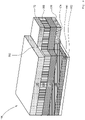
- the figure 3 shows a schematic, perspective view of the touch-sensitive unit of the operating unit according to FIG figures 1 , 2 .
- the touch-sensitive unit 106 comprises the diffuser film 116 with the character layer 130 facing the operator and the functional layer 148 pointing away from the operator, i.e. downwards.
- the functional layer 148 is protected on the underside by the protective layer 188 from harmful environmental influences such as corrosion, moisture and mechanical damage.
- Below the protective layer 188 runs the adhesive layer 190, which in turn is provided with the non-adhesive, film-like peelable layer 192 to improve handling during the assembly process of the operating unit.
- the character layer 130 is omitted above an extension 300 of the diffuser film 116 and the reinforcement 172 is applied at a distance from the character layer 130, preferably creating a gap 302.
- the functional layer 148 runs below the extension 300 of the diffuser film 116 and is essentially congruent with it.
- the first electrical interface 178 is formed on the underside 174 of the functional layer 148 and is at least slightly overlapped by the protective layer 188 of the functional layer 148.
- the character layer 130 of the diffuser film 116 does not yet have any characters formed by means of laser radiation from a suitable laser.
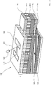
- the figure 4 shows the touch-sensitive unit of 3 with an exemplary character formed by means of laser radiation from a suitable laser.
- the layer structure (so-called "stack") of the touch-sensitive unit 106 has starting from the user-facing character layer 130 via the diffuser film 116, the functional layer 148, the protective layer 188, the adhesive layer 190 and the peel-off layer 192. Above the extension 300 of the diffuser film 116, the stiffening 172 is arranged.
- the first electrical interface 178 is positioned below an extension 304 of the functional layer 148 so as to be essentially congruent with the reinforcement 172 .
- a character 310 which represents the Latin capital letter "H" is introduced into the character layer 130 with the aid of laser radiation 312 from a suitable laser 320, merely as an example.
- the character 310 here, for example, completely penetrates a material thickness M of the character layer 130 and thus forms a character cutout 322 that is transparent to the light of the LED unit (not shown here) without loss.
- the use of the laser radiation 312 of a laser inscribing device ensures an extremely sharp contour, highly dimensionally accurate and reliably reproducible geometric design of the individual characters.
- the intensity of the laser radiation 312 or the power of the laser 320 is measured in such a way that when the characters are formed in the character layer 130 damage to the diffuser film 116 lying underneath is ruled out.
- the characters of the character layer 130 can be produced by means of the laser 320 without any problems after the assembly of the touch-sensitive unit and the LED unit for creating the operating unit has been completed—ie immediately before they are installed in a household appliance.
- the invention relates to an operating unit 100 for a household appliance with a touch-sensitive unit 106 and an LED unit 112 positioned on the rear of this, the touch-sensitive unit 106 being formed with a diffuser film 116, the top side 122 of which, facing an operator, has at least one character layer 130 and its one thereof facing away from underside 142 has at least one functional layer 148 having.
- the at least one character layer 130 has at least one character 154, 156, 250, 252, 254, 256, 258 produced by means of laser radiation 312, which is at least partially transparent to light from the LED unit 112, with the character layer 130 outside of the at least one character 154, 156, 250, 252, 254, 256, 258 for light 164, 166 of the LED unit 112 is opaque.
- the operating unit 100 has a high level of variability and can be easily adapted for different types and/or types of household appliances with little effort.
Landscapes
- Physics & Mathematics (AREA)
- General Physics & Mathematics (AREA)
- Engineering & Computer Science (AREA)
- Theoretical Computer Science (AREA)
- Push-Button Switches (AREA)
- Switches That Are Operated By Magnetic Or Electric Fields (AREA)
- Illuminated Signs And Luminous Advertising (AREA)
Applications Claiming Priority (1)
| Application Number | Priority Date | Filing Date | Title |
|---|---|---|---|
| DE102020215166.0A DE102020215166A1 (de) | 2020-12-02 | 2020-12-02 | Bedieneinheit für ein Haushaltsgerät |
Publications (2)
| Publication Number | Publication Date |
|---|---|
| EP4009527A1 true EP4009527A1 (fr) | 2022-06-08 |
| EP4009527B1 EP4009527B1 (fr) | 2026-03-04 |
Family
ID=78770425
Family Applications (1)
| Application Number | Title | Priority Date | Filing Date |
|---|---|---|---|
| EP21209808.1A Active EP4009527B1 (fr) | 2020-12-02 | 2021-11-23 | Unité de commande pour un appareil électroménager |
Country Status (3)
| Country | Link |
|---|---|
| EP (1) | EP4009527B1 (fr) |
| CN (1) | CN114584128A (fr) |
| DE (1) | DE102020215166A1 (fr) |
Families Citing this family (1)
| Publication number | Priority date | Publication date | Assignee | Title |
|---|---|---|---|---|
| DE102024129131A1 (de) * | 2024-10-09 | 2026-04-09 | Miele & Cie. Kg | Haushaltsgerät |
Citations (5)
| Publication number | Priority date | Publication date | Assignee | Title |
|---|---|---|---|---|
| EP1903284A1 (fr) * | 2006-08-26 | 2008-03-26 | Electrolux Home Products Corporation N.V. | Dispositif pour appareil ménager et son utilisation |
| US20100142211A1 (en) * | 2008-11-04 | 2010-06-10 | Boelstler Richard A | Assembly for illuminating a control panel |
| DE202014101897U1 (de) * | 2013-12-10 | 2015-03-11 | Pas Deutschland Gmbh | Einrichtung zur Bedienerführung, Blendenbauteil, Bedienanordnung sowie Haushaltsgerät mit einem Blendenbauteil |
| DE102015013054A1 (de) * | 2015-10-08 | 2017-04-13 | Audi Ag | Variable Anordnung von Funktionen auf einem sensorischen Bedienteil |
| DE102019104435A1 (de) * | 2019-02-21 | 2020-08-27 | Miele & Cie. Kg | Bedienelemente, elektrisches Haushaltsgerät und Verfahren zur Herstellung eines solchen Bedienelements |
Family Cites Families (15)
| Publication number | Priority date | Publication date | Assignee | Title |
|---|---|---|---|---|
| DE102004061305A1 (de) * | 2004-12-20 | 2006-06-22 | BSH Bosch und Siemens Hausgeräte GmbH | Haushaltsgerät mit einem Anzeigeelement |
| DE102009020627A1 (de) | 2009-05-09 | 2010-11-11 | Hettich Holding Gmbh & Co. Ohg | Möbel |
| FR2958423B1 (fr) * | 2010-03-31 | 2012-06-08 | Valeo Systemes Thermiques | Module de commande tactile |
| DE102010030315A1 (de) * | 2010-06-21 | 2011-12-22 | BSH Bosch und Siemens Hausgeräte GmbH | Berührungsempfindliche Eingabeeinheit für ein Hausgerät sowie Hausgerät |
| DE102011081331A1 (de) | 2011-08-22 | 2013-02-28 | BSH Bosch und Siemens Hausgeräte GmbH | Haushaltsgerät mit einer berührungssensitiven Bedien- und Anzeigeeinrichtung |
| DE102013018989A1 (de) * | 2013-11-13 | 2015-05-13 | Valeo Schalter Und Sensoren Gmbh | Berührungssensitiver Schalter für ein Kraftfahrzeug und Kraftfahrzeug |
| EP3084963B1 (fr) * | 2013-12-17 | 2019-05-15 | Electrolux Appliances Aktiebolag | Agencement d'interface utilisateur |
| DE102014200316A1 (de) * | 2014-01-10 | 2015-07-16 | BSH Hausgeräte GmbH | Hausgerätebedienvorrichtung |
| DE102015201427A1 (de) * | 2015-01-28 | 2016-07-28 | BSH Hausgeräte GmbH | Berührungsempfindliches, beleuchtbares Bedienpanel, Verfahren zu seinem Betrieb sowie dieses Bedienpanel enthaltendes Hausgerät |
| DE102016113162A1 (de) | 2015-07-28 | 2017-02-02 | Schott Ag | Bedienblende für ein Haushaltsgerät mit zumindest einer Benutzerschnittstelle, Haushaltsgerät und Verfahren zur Herstellung der Bedienblende mit Benutzerschnittstelle |
| KR101804636B1 (ko) * | 2015-10-30 | 2017-12-05 | 엘에스오토모티브 주식회사 | 터치 스위치 유니트 및 이를 구비하는 차량 실내 조명 장치 |
| CN107541903B (zh) * | 2016-06-29 | 2020-04-24 | 青岛海尔洗衣机有限公司 | 一种用于家电的操作显示装置及洗衣机 |
| DE102016212995A1 (de) * | 2016-07-15 | 2018-01-18 | BSH Hausgeräte GmbH | Bedienmodul für ein Haushaltsgerät |
| DE202019005292U1 (de) | 2019-03-22 | 2020-02-10 | Hib Trim Part Solutions Gmbh | Fahrzeugzierteil |
| CN209843555U (zh) * | 2019-06-28 | 2019-12-24 | 武汉海微科技有限公司 | 一种触摸感应式方向盘按键面板的叠层结构 |
-
2020
- 2020-12-02 DE DE102020215166.0A patent/DE102020215166A1/de active Pending
-
2021
- 2021-11-23 EP EP21209808.1A patent/EP4009527B1/fr active Active
- 2021-12-01 CN CN202111450110.4A patent/CN114584128A/zh active Pending
Patent Citations (5)
| Publication number | Priority date | Publication date | Assignee | Title |
|---|---|---|---|---|
| EP1903284A1 (fr) * | 2006-08-26 | 2008-03-26 | Electrolux Home Products Corporation N.V. | Dispositif pour appareil ménager et son utilisation |
| US20100142211A1 (en) * | 2008-11-04 | 2010-06-10 | Boelstler Richard A | Assembly for illuminating a control panel |
| DE202014101897U1 (de) * | 2013-12-10 | 2015-03-11 | Pas Deutschland Gmbh | Einrichtung zur Bedienerführung, Blendenbauteil, Bedienanordnung sowie Haushaltsgerät mit einem Blendenbauteil |
| DE102015013054A1 (de) * | 2015-10-08 | 2017-04-13 | Audi Ag | Variable Anordnung von Funktionen auf einem sensorischen Bedienteil |
| DE102019104435A1 (de) * | 2019-02-21 | 2020-08-27 | Miele & Cie. Kg | Bedienelemente, elektrisches Haushaltsgerät und Verfahren zur Herstellung eines solchen Bedienelements |
Also Published As
| Publication number | Publication date |
|---|---|
| EP4009527B1 (fr) | 2026-03-04 |
| CN114584128A (zh) | 2022-06-03 |
| DE102020215166A1 (de) | 2022-06-02 |
Similar Documents
| Publication | Publication Date | Title |
|---|---|---|
| EP1994216B1 (fr) | Agencement de bandeau de commande pour des appareils ménagers et procédé de fabrication d'un agencement de bandeau de commande | |
| EP2723930B1 (fr) | Dispositif de commande et d'affichage d'un appareil menager et appareil menager | |
| EP1042713B1 (fr) | Procede de transfert de caracteres en particulier a un ordinateur, et dispositif d'entree fonctionnant selon ce procede | |
| DE102011056711B4 (de) | Näherungssensor mit einer elastomeren mehrschichtanordnung | |
| DE4443912C2 (de) | Bedienvorrichtung in Kraftfahrzeugen | |
| EP2748369B1 (fr) | Appareil ménager à système de commande et d'affichage tactile | |
| DE112014006972B4 (de) | Eingabeeinrichtung und Steuerverfahren für dieselbe | |
| EP1788473A1 (fr) | dispositif d'entrée | |
| EP2544915B1 (fr) | Dispositif de commande servant à entrer des instructions de commande dans un appareil électronique | |
| WO2018099657A1 (fr) | Dispositif d'entrée présentant un réseau de capteurs de force dans la structure de couches de films avec rétro-éclairage | |
| EP0378649B1 (fr) | Dispositif pour introduire des donnees de commande dans une machine-outil cnc | |
| EP4173870A1 (fr) | Console de commande | |
| EP4077049A1 (fr) | Unité d'actionnement pour un véhicule à moteur | |
| EP4009527B1 (fr) | Unité de commande pour un appareil électroménager | |
| DE202012103075U1 (de) | Bedienflächenelement, Bedieneinheit und Gerät | |
| DE2844575C2 (de) | Eingabevorrichtung | |
| DE102016108899A1 (de) | Kombiniertes Ein- und Ausgabegerät und Verfahren zur Bedienung eines Ein- und Ausgabegerätes | |
| EP3537049B1 (fr) | Champ de cuisson et procédé de représentation d'un affichage sur cet champ de cuisson | |
| DE102023105043A1 (de) | Eingabevorrichtung | |
| DE102014019439B4 (de) | Verkleidungsvorrichtung für ein Kraftfahrzeug und Kraftfahrzeug | |
| DE68904668T2 (de) | Kommunikationsterminal mit veraenderbarer zusammensetzung. | |
| EP1177566B1 (fr) | Dispositif permettant d'entrer des valeurs et dote d'un ecran | |
| DE4216281C2 (de) | Steuervorrichtung für Cockpits von Flugzeugen | |
| DE102020122189A1 (de) | Zierteil mit einstückiger aus Festsilikonen gebildeter Multifunktionsschicht | |
| EP4180931A1 (fr) | Appareil d'interface utilisateur comprenant un écran tactile |
Legal Events
| Date | Code | Title | Description |
|---|---|---|---|
| PUAI | Public reference made under article 153(3) epc to a published international application that has entered the european phase |
Free format text: ORIGINAL CODE: 0009012 |
|
| STAA | Information on the status of an ep patent application or granted ep patent |
Free format text: STATUS: THE APPLICATION HAS BEEN PUBLISHED |
|
| AK | Designated contracting states |
Kind code of ref document: A1 Designated state(s): AL AT BE BG CH CY CZ DE DK EE ES FI FR GB GR HR HU IE IS IT LI LT LU LV MC MK MT NL NO PL PT RO RS SE SI SK SM TR |
|
| STAA | Information on the status of an ep patent application or granted ep patent |
Free format text: STATUS: REQUEST FOR EXAMINATION WAS MADE |
|
| 17P | Request for examination filed |
Effective date: 20221208 |
|
| RBV | Designated contracting states (corrected) |
Designated state(s): AL AT BE BG CH CY CZ DE DK EE ES FI FR GB GR HR HU IE IS IT LI LT LU LV MC MK MT NL NO PL PT RO RS SE SI SK SM TR |
|
| STAA | Information on the status of an ep patent application or granted ep patent |
Free format text: STATUS: EXAMINATION IS IN PROGRESS |
|
| 17Q | First examination report despatched |
Effective date: 20240205 |
|
| GRAP | Despatch of communication of intention to grant a patent |
Free format text: ORIGINAL CODE: EPIDOSNIGR1 |
|
| STAA | Information on the status of an ep patent application or granted ep patent |
Free format text: STATUS: GRANT OF PATENT IS INTENDED |
|
| INTG | Intention to grant announced |
Effective date: 20251016 |
|
| GRAS | Grant fee paid |
Free format text: ORIGINAL CODE: EPIDOSNIGR3 |
|
| GRAA | (expected) grant |
Free format text: ORIGINAL CODE: 0009210 |
|
| STAA | Information on the status of an ep patent application or granted ep patent |
Free format text: STATUS: THE PATENT HAS BEEN GRANTED |
|
| AK | Designated contracting states |
Kind code of ref document: B1 Designated state(s): AL AT BE BG CH CY CZ DE DK EE ES FI FR GB GR HR HU IE IS IT LI LT LU LV MC MK MT NL NO PL PT RO RS SE SI SK SM TR |
|
| REG | Reference to a national code |
Ref country code: CH Ref legal event code: F10 Free format text: ST27 STATUS EVENT CODE: U-0-0-F10-F00 (AS PROVIDED BY THE NATIONAL OFFICE) Effective date: 20260304 Ref country code: GB Ref legal event code: FG4D Free format text: NOT ENGLISH |
|
| REG | Reference to a national code |
Ref country code: IE Ref legal event code: FG4D Free format text: LANGUAGE OF EP DOCUMENT: GERMAN |
|
| REG | Reference to a national code |
Ref country code: DE Ref legal event code: R096 Ref document number: 502021009952 Country of ref document: DE |