EP4009750B1 - Plasma-vorrichtung - Google Patents
Plasma-vorrichtung Download PDFInfo
- Publication number
- EP4009750B1 EP4009750B1 EP21209794.3A EP21209794A EP4009750B1 EP 4009750 B1 EP4009750 B1 EP 4009750B1 EP 21209794 A EP21209794 A EP 21209794A EP 4009750 B1 EP4009750 B1 EP 4009750B1
- Authority
- EP
- European Patent Office
- Prior art keywords
- upper shell
- plasma
- plasma device
- lower shell
- housing
- Prior art date
- Legal status (The legal status is an assumption and is not a legal conclusion. Google has not performed a legal analysis and makes no representation as to the accuracy of the status listed.)
- Active
Links
Images


Classifications
-
- H—ELECTRICITY
- H05—ELECTRIC TECHNIQUES NOT OTHERWISE PROVIDED FOR
- H05H—PLASMA TECHNIQUE; PRODUCTION OF ACCELERATED ELECTRICALLY-CHARGED PARTICLES OR OF NEUTRONS; PRODUCTION OR ACCELERATION OF NEUTRAL MOLECULAR OR ATOMIC BEAMS
- H05H1/00—Generating plasma; Handling plasma
- H05H1/24—Generating plasma
- H05H1/2406—Generating plasma using dielectric barrier discharges, i.e. with a dielectric interposed between the electrodes
-
- A—HUMAN NECESSITIES
- A61—MEDICAL OR VETERINARY SCIENCE; HYGIENE
- A61L—METHODS OR APPARATUS FOR STERILISING MATERIALS OR OBJECTS IN GENERAL; DISINFECTION, STERILISATION OR DEODORISATION OF AIR; CHEMICAL ASPECTS OF BANDAGES, DRESSINGS, ABSORBENT PADS OR SURGICAL ARTICLES; MATERIALS FOR BANDAGES, DRESSINGS, ABSORBENT PADS OR SURGICAL ARTICLES
- A61L2/00—Disinfection or sterilisation of materials or objects, in general; Accessories therefor
- A61L2/02—Disinfection or sterilisation of materials or objects, in general; Accessories therefor using physical processes
- A61L2/14—Plasma, i.e. ionised gases
-
- D—TEXTILES; PAPER
- D06—TREATMENT OF TEXTILES OR THE LIKE; LAUNDERING; FLEXIBLE MATERIALS NOT OTHERWISE PROVIDED FOR
- D06M—TREATMENT, NOT PROVIDED FOR ELSEWHERE IN CLASS D06, OF FIBRES, THREADS, YARNS, FABRICS, FEATHERS OR FIBROUS GOODS MADE FROM SUCH MATERIALS
- D06M10/00—Physical treatment of fibres, threads, yarns, fabrics or fibrous goods made from such materials, e.g. by ultrasonic waves, corona discharge, irradiation, electric currents or magnetic fields; Physical treatment combined with treatment with chemical compounds or elements
- D06M10/02—Sonic or ultrasonic waves; Corona discharge
- D06M10/025—Corona discharge or low temperature plasma
-
- A—HUMAN NECESSITIES
- A61—MEDICAL OR VETERINARY SCIENCE; HYGIENE
- A61L—METHODS OR APPARATUS FOR STERILISING MATERIALS OR OBJECTS IN GENERAL; DISINFECTION, STERILISATION OR DEODORISATION OF AIR; CHEMICAL ASPECTS OF BANDAGES, DRESSINGS, ABSORBENT PADS OR SURGICAL ARTICLES; MATERIALS FOR BANDAGES, DRESSINGS, ABSORBENT PADS OR SURGICAL ARTICLES
- A61L2103/00—Materials or objects being the target of disinfection or sterilisation
- A61L2103/50—Textiles, e.g. bedwear or towels
-
- A—HUMAN NECESSITIES
- A61—MEDICAL OR VETERINARY SCIENCE; HYGIENE
- A61L—METHODS OR APPARATUS FOR STERILISING MATERIALS OR OBJECTS IN GENERAL; DISINFECTION, STERILISATION OR DEODORISATION OF AIR; CHEMICAL ASPECTS OF BANDAGES, DRESSINGS, ABSORBENT PADS OR SURGICAL ARTICLES; MATERIALS FOR BANDAGES, DRESSINGS, ABSORBENT PADS OR SURGICAL ARTICLES
- A61L2202/00—Aspects relating to methods or apparatus for disinfecting or sterilising materials or objects
- A61L2202/10—Apparatus features
- A61L2202/11—Apparatus for generating biocidal substances, e.g. vaporisers, UV lamps
-
- A—HUMAN NECESSITIES
- A61—MEDICAL OR VETERINARY SCIENCE; HYGIENE
- A61L—METHODS OR APPARATUS FOR STERILISING MATERIALS OR OBJECTS IN GENERAL; DISINFECTION, STERILISATION OR DEODORISATION OF AIR; CHEMICAL ASPECTS OF BANDAGES, DRESSINGS, ABSORBENT PADS OR SURGICAL ARTICLES; MATERIALS FOR BANDAGES, DRESSINGS, ABSORBENT PADS OR SURGICAL ARTICLES
- A61L2202/00—Aspects relating to methods or apparatus for disinfecting or sterilising materials or objects
- A61L2202/10—Apparatus features
- A61L2202/14—Means for controlling sterilisation processes, data processing, presentation and storage means, e.g. sensors, controllers, programs
Definitions
- the present invention relates to a plasma device for treating surfaces, in particular textiles, according to the preamble of claim 1.
- the plasma device for inactivating molecules that are preferably odor-relevant and thus for refreshing surfaces, for example in textiles.
- the plasma device has a housing and an associated plasma source.
- a cleaning device for cleaning clothes is known, with a housing in which a receiving space is provided for receiving a blower. Also provided in the receiving space is a separator which separates an air inlet area from a cleaning area. The areas mentioned are arranged vertically one above the other in the operating state.
- the cleaning device can be used to remove or clean the items of clothing to be treated, in particular from cigarette smoke.
- plasma is referred to as the fourth state of matter. If a sufficient amount of energy is added to a gas or gas mixture, for example in the form of electrical energy, some atoms of the gas are ionized, i.e. electrons are removed from the atomic shell and move as free particles, leaving a positively charged atom behind. If a gas consists of a sufficiently high proportion of free ions and electrons, the state of aggregation is called plasma. Plasma is therefore matter whose components are partially charged components, ions and electrons, which act as free charge carriers move.
- Non-thermal plasma also known as cold plasma
- Non-thermal plasmas are also used in medical technology, for example in the treatment of poorly or non-healing wounds with the help of a so-called plasma pen, using the antimicrobial effect of "cold plasma”.
- the causes of the antibacterial effect of a plasma are heat, drying, shear stress, UV radiation, free radicals and charges.
- heat plays a minor role since these plasmas are operated at room temperature.
- reactive particles are formed, such as various oxygen or nitrogen species, which have a sufficiently long lifespan to damage organic compounds upon indirect exposure. These particles include, among others, atomic oxygen, superoxide radicals, ozone, hydroxyl radicals, nitrogen monoxide and nitrogen dioxide. These particles have a destructive effect on a wide variety of odor components as well as cell components.
- odor components which usually consist of carbon compounds, as well as cell walls of bacteria, germs, viruses, fungi or other comparable microorganisms are exposed directly to the plasma, they become negatively charged due to the bombardment with the electrons present in the plasma. Due to the electrostatic repulsion, this leads to mechanical stress up to the point where the tensile strength is exceeded and the destruction of the odor molecule or the cell wall. But not only mechanical tension due to the charge can destroy the cell walls, but also the disruption of the charge balance of the odor molecules or the cell wall through various other electrostatic interactions and electrolysis, e.g. B. by changing the permeability of the cell walls. A mechanism for inactivating microorganisms also results from the very high-energy ions.
- the plasma can be generated using high frequency. Low-pressure plasmas are therefore particularly suitable for inactivating odors on textile fabrics or on common household surfaces or the like in order to achieve odor activation.
- the surfaces to be treated can be textile materials with natural, plant or animal fibers, such as: B. cotton, sheep's wool, silk, linen, felt or artificial fibers such as. B. nylon.
- the term “surface” should also be understood to include materials and objects made of ceramic, plastic, feathers, leather, glass, wood, or metal.
- a disadvantage of the plasma device known from the prior art is that an energy storage device is installed in such a way that a voltage supply may not be interrupted even when the housing is open. However, this could possibly lead to damage to an electronic unit or the plasma source.
- the present invention is therefore concerned with the problem of providing an improved or at least an alternative embodiment for a plasma device of the generic type, which in particular protects electronic components of the plasma device during maintenance or repair or even in the event of a fall from unwanted electrical Voltage protects.
- the present invention is based on the general idea of equipping a known plasma device for treating surfaces, in particular for refreshing textiles, with a housing with two shells, namely an upper shell and a lower shell, and a power supply for an electronic unit or a plasma source
- the plasma device within the housing must be designed so that it is interrupted if the housing is opened beyond a certain extent.
- the plasma device according to the invention has a housing with a lower shell and an upper shell pivotally mounted thereon, with a receptacle for the electrical energy storage, for example a battery or an accumulator, being provided in the upper shell.
- the plasma source and the electronic device for example a printed circuit board, are located in the lower shell.
- the electronic device has electrical contact elements which are electrically connected to the energy storage when the housing is closed, that is to say when the upper shell is firmly connected to the lower shell, and thereby electrically connect the energy storage to the electronic device and above to the plasma source.
- the voltage supply is interrupted according to the invention, so that the energy storage is no longer electrically conductively connected to the contact elements from the aforementioned opening angle ⁇ . This can ensure that the electronic device, for example a circuit board, is protected from voltage damage, which can be caused, for example, by an unwanted current or an undesirable voltage in the circuit board.
- the variant with an upper shell and a lower shell can be used to create a reliable and cost-effective variant for de-energizing both the electronic device and the plasma source, without the need for additional components such as screws, flaps, snap hooks or the like.
- the power supply of the electronic device and the plasma source coupled to the closed position of the housing of the plasma device also offer the great advantage that if the plasma device falls down and the housing is opened, the electrical energy storage is immediately electrically isolated from the contact elements of the electronic device.
- the housing is usually constructed in such a way that it can open in the event of a fall, thereby interrupting the power supply to the electronic device or the plasma source.
- the opening angle ⁇ preferably extends in a vertical longitudinal plane.
- the upper shell and the lower shell are fixed to one another in the closed state via a locking element and/or a screw and/or a split pin.
- a locking element in particular enabling the housing to be easily closed by, for example, pressing the upper shell against the lower shell without any additional tools.
- the housing can be opened by pushing back the locking element and thus releasing its locking position.
- the upper shell and the lower shell are fixed to one another in the closed state via a screw, such a screw being able to represent a type of lock function, for example via a corresponding head with a corresponding tool engagement, so that the screw can only be unscrewed with a suitably designed tool (key) and the housing is opened can be.
- a split pin can also be provided, which enables simple and user-friendly opening.
- a maximum distance d of the upper shell from the lower shell is expediently approximately 14 mm.
- the distance d is taken at a longitudinal end of the plasma device opposite the pivot axis.
- the contact elements on the electronic device are designed as spring clips.
- Such spring clips enable the contact elements to be preloaded against the poles of the energy storage device, thereby enabling reliable energy transmission.
- the spring clips can also be used to compensate for dimensional or manufacturing tolerances.
- An excavator shovel-like element is expediently arranged on the upper shell and a guide designed to complement it on the lower shell, in which the element is guided during a pivoting movement of the upper shell.
- Such an excavator shovel-like element and a guide designed to complement it enable a pivoting movement of the upper shell relative to the lower shell and at the same time a removal of the upper shell from the lower shell if a predefined opening angle, for example ⁇ > 90 °, is exceeded.
- a predefined opening angle for example ⁇ > 90 °
- a plateau surface running in the longitudinal direction of the housing is expediently provided on the lower shell with at least one electrode, via which plasma can be generated or applied to the surface to be treated, the plateau surface being spring-loaded and protruding beyond the housing when the plasma device is not in use.
- the electrode can also be slightly raised in relation to the plateau surface and, for example, have a line-like shape.
- the electrode can be surrounded by a ceramic substrate.
- the spring-loaded plateau surface also has the effect of shielding the emitted plasma from atmospheric oxygen, so that although sufficient oxygen is available for ozone production, the aforementioned excessive ozone production with the associated disadvantages does not take place.
- the disadvantages of excessive ozone production are, particularly in the case of prolonged exposure to the surface to be treated, for example a textile, discoloration or discoloration of the surface and the risk of respiratory irritation.
- the odor-relevant molecules that can be neutralized with the plasma device according to the invention can be butyric acid, sweat, settled cigarette smoke or general odors that can be perceived as unpleasant.
- the plasma device is based on the fact that the odors are actively eliminated and not unpleasant smells, e.g. B. can be covered up with perfume.
- the plasma device according to the invention can also be used to destroy molecules that are not relevant to odor, such as allergens, protein molecules, prions, etc.
- a plasma device 1 for treating surfaces, for example for refreshing textiles, has a housing 2 with a lower shell 3 and an upper shell 4 pivotally mounted thereon.
- the electronic device 8 can be designed, for example, as a circuit board and serve to control the plasma source 7.
- the electrical contact element 9a of the electronic device 8 loses contact with the electrical energy storage 6 from a predefined opening angle ⁇ ⁇ 5 °, whereby the voltage supply to the Electronic device 8 and thus also the plasma source 7 is interrupted.
- This Situation is according to the Fig. 4 shown.
- the opening state of the housing 2 is shown exactly, in which the contact element 9a is still just connected to the energy storage 6.
- a maximum distance d of the upper shell 4 from the lower shell 3 is approximately 14 mm.
- the maximum distance d is read on the side of the plasma device 1 opposite the pivot axis 10.
- the opening angle ⁇ lies in the plane of the blade, that is, in a vertical longitudinal plane relative to the plasma device 1.
- the contact element 9b also loses contact with the electrical energy storage 6, whereby it is completely electrically isolated from the contact elements 9a and 9b.
- the electrical energy storage 6 is fixed in the receptacle 5 of the upper shell 4, so that by completely opening the upper shell 4, the electrical energy storage 6 can simply be pressed into the receptacle 5 from above or pulled out of it again.
- the electrical energy storage 6 is held using corresponding holding elements 17, for example clamping elements, even when the receptacle 5 is open at the bottom, as shown in FIG Fig. 3 to 5 and Fig. 8 is shown, held reliably. If you look at them Fig.
- holding elements 17, 17a are provided, which encompass the electrical energy storage 6 both on its circumference and on its end face 18.
- the holding elements 17a thus form a kind of shoe for the energy storage 6.
- the other holding elements 17 are designed as resilient clamping elements 17b and bias the energy storage device 6 into the receptacle 5.
- the electrical energy storage 6 engages in a corresponding recess 19 in the electronic device 8, for example the circuit board.
- an optional protective wall 16 is also shown, which protects the energy storage 6 and causes stiffening, for example by engaging in an associated opening on the electronic device 8. Furthermore, direct contact of the contact surface of the energy storage 6 with needle-like objects from the opening side is made more difficult.
- the plasma device 1 With the plasma device 1 according to the invention it can be ensured that when the housing 2 is opened, a reliable voltage interruption occurs at the Electronic device 8 and the plasma source 7 can be guaranteed, whereby voltage or current damage in particular can be reliably avoided. With the housing 2 according to the invention it can also be avoided that if the plasma device 1 accidentally falls and the housing 2 is opened, a further voltage/current supply to the electronic device 8 takes place.
- the contact elements 9a, 9b can be designed, for example, as spring clips and are therefore able to easily compensate for at least small installation tolerances of the energy storage device 6 in the receptacle 5, as well as manufacturing tolerances.
- the upper shell 4 and the lower shell 3 are secured via, for example, a locking element 20 (cf. Fig. 8 ) or a screw (not shown) and/or a cotter pin are fixed together, with the locking element 20 mentioned in particular enabling the housing 2 to be closed without further tools.
- a type of lock could be created, which enables the screw to be opened and thus the housing 2 to be opened exclusively with a suitable tool, that is to say a suitable key.
- the Guide 12 preferably has two circular segment-like outer guide contours 12a and an inner guide contour 12b arranged between them, over which the element 11 is guided on both an outside and an inside.
- a plateau surface 14 running in the longitudinal direction 13 of the housing 2 with at least one electrode 15 is provided on the lower shell 3, via which plasma can be generated or applied to the surface to be treated (see. Fig. 2 to 5 ).
- the plateau surface 14 is preferably spring-loaded and is in a non-use state of the plasma device 1 (cf. the Fig. 2 to 5 ) over the housing 2, that is in this case over the lower shell 3 downwards.
- spring-loading the plateau surface 14 it is possible to move it close to the surface to be cleaned or refreshed while the plasma device 1 is being used, whereby in particular excessive ozone production by the plasma source 7 can be prevented. This can prevent respiratory irritation as well as unwanted discoloration or discoloration of the surface to be cleaned due to excessive ozone concentration.
- the plasma device 1 With the plasma device 1 according to the invention, it is possible to create easy accessibility for maintenance and repair purposes and at the same time to ensure that the plasma device 1 is isolated from the electrical energy storage device 6 from a predefined degree of opening of the housing 2 and is therefore de-energized.
Landscapes
- Engineering & Computer Science (AREA)
- Plasma & Fusion (AREA)
- Physics & Mathematics (AREA)
- Health & Medical Sciences (AREA)
- Life Sciences & Earth Sciences (AREA)
- Epidemiology (AREA)
- Spectroscopy & Molecular Physics (AREA)
- Animal Behavior & Ethology (AREA)
- General Health & Medical Sciences (AREA)
- Public Health (AREA)
- Veterinary Medicine (AREA)
- Textile Engineering (AREA)
- Plasma Technology (AREA)
Description
- Die vorliegende Erfindung betrifft eine Plasma-Vorrichtung zum Behandeln von Oberflächen, insbesondere bei Textilien, gemäß dem Oberbegriff des Anspruchs 1.
- Aus der
DE 10 2011 100 751 A1 ist eine gattungsgemäße Plasma-Vorrichtung zur Inaktivierung vorzugsweise geruchsrelevanter Moleküle und damit zum Auffrischen von Oberflächen, beispielsweise bei Textilien, bekannt. Die Plasma-Vorrichtung weist ein Gehäuse sowie eine zugeordnete Plasmaquelle auf. - Aus der
CN 108 771 767 A ist eine Reinigungsvorrichtung zum Reinigen von Kleidern bekannt, mit einem Gehäuse, in dem ein Aufnahmeraum zur Aufnahme eines Gebläses vorgesehen ist. Ebenfalls in dem Aufnahmeraum vorgesehen ist ein Abscheider, der einen Lufteinlassbereich von einem Reinigungsbereich trennt. Die genannten Bereiche sind dabei im Betriebszustand vertikal übereinander angeordnet. Mit der Reinigungsvorrichtung lassen sich die zu behandelnden Kleidungsstücke insbesondere auch von Zigarettenrauch befreien bzw. reinigen. - Weitere gattungsgemäße Plasmavorrichtungen zur Behandlung von Oberflächen sind aus den Dokumenten
WO 2020/083993 A1 ,DE 10 2018 213143 A1 ,WO 2015/110787 A1 undDE 10 2017 118568 B3 bekannt. - Zur Reinigung von Kleidungsstücken können diese gewaschen bzw. auch chemisch gereinigt werden, wobei zunehmend auch eine Auffrischung bzw. Behandlung mittels Plasma in den Fokus der Betrachtung rückt, wobei dieses Plasma in der Lage ist, Geruchsmoleküle zu zerstören und dadurch negative Gerüche zu eliminieren. Gleichzeitig wirkt derartiges Plasma antibakteriell und antimikrobiell.
- Neben den drei Aggregatzuständen fest, flüssig oder gasförmig, wird Plasma als vierter Aggregatzustand bezeichnet. Wird einem Gas oder Gasgemisch hinreichend viel Energie, beispielsweise in Form von elektrischer Energie, zugefügt, so werden einige Atome des Gases ionisiert, d.h. Elektronen werden aus der Atomhülle entfernt und bewegen sich als freie Teilchen, sodass ein positiv geladenes Atom zurückbleibt. Wenn ein Gas aus einem ausreichend hohen Anteil an freien Ionen und Elektronen besteht, so bezeichnet man den Aggregatzustand als Plasma. Plasma ist also Materie, dessen Bestandteile teilweise geladene Komponenten, Ionen und Elektronen sind, die sich als freie Ladungsträger bewegen.
- Nichtthermischem Plasma, das auch als kaltes Plasma bezeichnet wird, kann gezielt zur Beseitigung von Gerüchen und bestimmten Kohlenwasserstoffen eingesetzt werden. Weiterhin finden nichtthermische Plasmen Anwendung in der Medizintechnik, zum Beispiel bei der Behandlung von schlecht oder nicht heilenden Wunden mit Hilfe eines sogenannten Plasmastifts, indem auf die antimikrobielle Wirkung von "kaltem Plasma" zurückgegriffen wird.
- Die Ursachen der antibakteriellen Wirkung eines Plasmas liegen in Hitze, Austrocknung, Scherspannung, UV-Strahlung, freie Radikale und Ladungen. Bei kalten Plasmen, wie sie in der erfindungsgemäßen Plasma-Vorrichtung verwendet werden, spielt die Hitze eine untergeordnete Rolle, da diese Plasmen bei Raumtemperatur betrieben werden. In solchen Niederdruckplasmen entstehen besonders reaktive Partikel, wie beispielsweise verschiedene Sauerstoff- oder Stickstoffspezies, die eine ausreichend hohe Lebensdauer aufweisen, um bei einer indirekten Exposition organische Verbindungen zu schädigen. Zu diesen Partikeln zählen unter anderem atomarer Sauerstoff, Superoxidradikale, Ozon, Hydroxylradikale, Stickstoffmonooxid und Stickstoffdioxid. Diese Partikel zeigen eine zerstörerische Wirkung auf unterschiedlichste Geruchskomponenten wie auch Zellkomponenten. Werden Geruchskomponenten, welche meist aus Kohlenstoffverbindungen bestehen, wie auch Zellwände von Bakterien, Keimen, Viren, Pilzen oder anderen vergleichbaren Mikroorganismen dem Plasma direkt ausgesetzt, so laden sich diese aufgrund des Beschusses mit den im Plasma vorhandenen Elektronen negativ auf. Aufgrund der elektrostatischen Abstoßung führt dies zu mechanischen Spannungen bis hin zur Überschreitung der Zugfestigkeit und der Zerstörung von dem Geruchsmolekül, bzw. der Zellwand. Aber nicht nur mechanische Verspannungen aufgrund der Ladung können die Zellwände zerstören, sondern auch die Störung des Ladungsgleichgewichts der Geruchsmoleküle, bzw. der Zellwand durch verschiedene, weitere elektrostatische Wechselwirkungen und der Elektrolyse, z. B. durch Änderung der Permeabilität der Zellwände. Ein Mechanismus zur Inaktivierung von Mikroorganismen ergibt sich auch aus den sehr energiereichen Ionen. Mittels einer Hochfrequenz kann das Plasma erzeugt werden. Niederdruckplasmen sind daher besonders gut zur Inaktivierung von Gerüchen an textilem Gewebe oder von haushaltsüblichen Oberflächen oder dergleichen geeignet, um eine Geruchsaktivierung zu erreichen.
- Die zu behandelnden Oberflächen können dabei textile Materialien mit natürlichen, pflanzlichen oder tierischen Fasern, wie z. B. Baum-, Schafwolle, Seide, Leinen, Filz oder künstlichen Fasern, wie z. B. Nylon, sein. Weiter sollen unter dem Begriff "Oberfläche" auch Materialien und Gegenstände aus Keramik, Kunststoff, Federn, Leder, Glas, Holz, oder Metall verstanden werden können.
- Nachteilig bei der aus dem Stand der Technik bekannten Plasma-Vorrichtung ist, dass ein Energiespeicher so eingebaut ist, dass selbst bei einem geöffneten Gehäuse eine Spannungsversorgung unter Umständen nicht unterbrochen ist. Dies könnte gegebenenfalls jedoch zu Schäden an einer Elektronikeinheit bzw. der Plasmaquelle führen.
- Die vorliegende Erfindung beschäftigt sich daher mit dem Problem, für eine Plasma-Vorrichtung der gattungsgemäßen Art eine verbesserte oder zumindest eine alternative Ausführungsform anzugeben, die insbesondere elektronische Komponenten der Plasma-Vorrichtung bei einer Wartung bzw. einer Reparatur oder auch bei einem Sturz vor unerwünschter elektrischer Spannung schützt.
- Dieses Problem wird erfindungsgemäß durch den Gegenstand des unabhängigen Anspruchs 1 gelöst. Vorteilhafte Ausführungsformen sind Gegenstand der abhängigen Ansprüche.
- Die vorliegende Erfindung beruht auf dem allgemeinen Gedanken, eine an sich bekannte Plasma-Vorrichtung zum Behandeln von Oberflächen, insbesondere zum Auffrischen von Textilien, mit einem Gehäuse mit zwei Schalen, nämlich einer Oberschale und einer Unterschale auszustatten und eine Spannungsversorgung einer Elektronikeinheit bzw. einer Plasmaquelle der Plasma-Vorrichtung innerhalb des Gehäuses konstruktiv so auszulegen, dass diese unterbrochen wird, sofern das Gehäuse über ein bestimmtes Maß hinaus geöffnet wird. Die erfindungsgemäße Plasma-Vorrichtung weist hierzu ein Gehäuse mit einer Unterschale sowie einer schwenkbar daran gelagerten Oberschale auf, wobei in der Oberschale eine Aufnahme für den elektrischen Energiespeicher, beispielsweise eine Batterie oder einen Akkumulator, vorgesehen ist. In der Unterschale sind die Plasmaquelle sowie die Elektronikeinrichtung, beispielsweise eine Leiterplatine, angeordnet, wobei die Elektronikeinrichtung elektrische Kontaktelemente aufweist, die bei geschlossenem Gehäuse, das heißt bei fest mit der Unterschale verbundener Oberschale elektrisch leitend mit dem Energiespeicher verbunden sind und dadurch den Energiespeicher elektrisch leitend mit der Elektronikeinrichtung und darüber mit der Plasmaquelle verbinden. Ab einem Öffnungswinkel α der Oberschale relativ zur Unterschale von α ≥ 5° ist die Spannungsversorgung erfindungsgemäß unterbrochen, so dass der Energiespeicher ab dem zuvor genannten Öffnungswinkel α nicht mehr elektrisch leitend mit den Kontaktelementen verbunden ist. Hierdurch kann erreicht werden, dass die Elektronikeinrichtung, beispielsweise eine Platine, vor Spannungsschäden geschützt ist, die beispielsweise durch einen ungewollt fließenden Strom bzw. eine unerwünschte Spannung in der Platine gegeben sein können. Zudem kann mit der Variante mit Oberschale und Unterschale eine zuverlässige und kostengünstige Variante geschaffen werden, sowohl die Elektronikeinrichtung als auch die Plasmaquelle spannungsfrei zu bekommen, ohne dass hierfür weitere Bauteile, wie beispielsweise Schrauben, Klappen, Schnapphaken oder ähnliches erforderlich wären. Die an die Schließstellung des Gehäuses der Plasma-Vorrichtung gekoppelte Spannungsversorgung der Elektronikeinrichtung und der Plasmaquelle bieten darüber hinaus den großen Vorteil, dass bei einem Herunterfallen der Plasma-Vorrichtung und einem Öffnen des Gehäuses der elektrische Energiespeicher unmittelbar elektrisch von den Kontaktelementen der Elektronikeinrichtung getrennt wird. Dabei ist das Gehäuse üblicherweise so konstruiert, dass sich dieses bei einem Sturz öffnen kann und dadurch die Spannungsversorgung der Elektronikeinrichtung bzw. der Plasmaquelle unterbrochen wird. Der Öffnungswinkel α erstreckt sich dabei vorzugsweise in einer vertikalen Längsebene.
- Bei einer vorteilhaften Weiterbildung der erfindungsgemäßen Lösung sind die Oberschale und die Unterschale in geschlossenem Zustand über ein Rastelement und/oder eine Schraube und/oder einem Splint aneinander fixiert. Selbstverständlich ist alternativ auch eine unter bestimmten Belastungen aufgehende Verklebung zwischen der Oberschale und der Unterschale denkbar, wobei insbesondere ein Rastelement ein einfaches Schließen des Gehäuses durch beispielsweise ein Aneinanderdrücken der Oberschale an die Unterschale ohne weiteres Werkzeug ermöglicht. Das Öffnen des Gehäuses kann durch ein Zurückdrücken des Rastelements und damit einem Lösen seiner Raststellung erreicht werden. Alternativ ist selbstverständlich auch denkbar, dass die Oberschale und die Unterschale im geschlossenen Zustand über eine Schraube aneinander fixiert sind, wobei eine derartige Schraube beispielsweise über einen entsprechenden Kopf mit einem entsprechenden Werkzeugeingriff eine Art Schlossfunktion darstellen kann, so dass die Schraube nur mit einem dazu passend ausgebildeten Werkzeug (Schlüssel) aufgedreht und das Gehäuse geöffnet werden kann. Hierdurch kann insbesondere die Gefahr eines Öffnens des Gehäuses durch Unbefugte, beispielsweise Laien, größtenteils ausgeschlossen werden. Wiederum alternativ kann auch ein Splint vorgesehen sein, der ein einfaches und nutzerfreundliches Öffnen ermöglicht.
- Zweckmäßig beträgt bei einem Öffnungswinkel α der Oberschale relativ zur Unterschale von ca. 5° ein maximaler Abstand d der Oberschale von der Unterschale ca. 14 mm. Der Abstand d ist dabei an einem der Schwenkachse gegenüber liegenden Längsende der Plasma-Vorrichtung abgenommen. Mit einem derartigen Abstand ist ein geringfügiges Aufschwenken der Oberschale relativ zur Unterschale möglich, ohne dass dabei die Spannungsversorgung der Elektronikeinrichtung bzw. der Plasmaquelle unterbrochen wird, während ein weiteres Öffnen des Gehäuses, das heißt ein weiteres Aufschwenken der Oberschale zwangsläufig zu einem Kontaktverlust zwischen dem Energiespeicher und den Kontaktelementen und damit einem stromlos schalten der Elektronikeinrichtung bzw. der Plasmaquelle führt. Rein theoretisch ist dabei denkbar, dass bei einem weiteren Öffnen der Oberschale über einen Winkel von α = 5° weitere Rastelemente gelöst werden müssen, so dass bei einem einfachen Herunterfallen der Plasma-Vorrichtung auf einen Fußboden zwar ein Öffnen des Gehäuses erfolgt, dies jedoch noch nicht unbedingt zu einem elektrischen Entkoppeln des Energiespeichers von der Elektronikeinrichtung führt. Dies bietet den großen Vorteil, dass die Plasma-Vorrichtung wieder aufgehoben und durch ein Zudrücken der Oberschale eine Wiederinbetriebnahme möglich ist. Für Reparatur- und Wartungszwecke genügt der Öffnungswinkel α von 5° nicht aus, so dass für diese Zwecke die Oberschale weiter aufgeschwenkt und damit das Gehäuse weiter geöffnet werden muss. Dies wiederum könnte beispielsweise nur dann möglich sein, sofern weitere Rastelemente gelöst werden.
- Bei einer vorteilhaften Weiterbildung der erfindungsgemäßen Lösung sind die Kontaktelemente an der Elektronikeinrichtung als Federbügel ausgebildet. Derartige Federbügel ermöglichen eine Federvorspannung der Kontaktelemente gegen die Pole des Energiespeichers, wodurch eine zuverlässige Energieübertragung ermöglicht wird.
- Durch die Federbügel können zudem Maßtoleranzen bzw. Fertigungstoleranzen kompensiert werden.
- Zweckmäßig sind an der Oberschale ein baggerschaufelartiges Element und an der Unterschale eine komplementär dazu ausgebildete Führung angeordnet, in der das Element bei einer Schwenkbewegung der Oberschale geführt ist. Ein derartiges baggerschaufelartiges Element sowie eine komplementär dazu ausgebildete Führung ermöglichen eine Schwenkbewegung der Oberschale relativ zur Unterschale und zugleich ein Abnehmen der Oberschale von der Unterschale, sofern ein vordefinierter Öffnungswinkel, beispielsweise α > 90° überschritten wird. Im Vergleich zu beispielsweise einem Scharnier lässt sich eine derartige Element-Führung-Verbindung konstruktiv einfach realisieren. Eine solche Verbindung erleichtert auch eine Reparatur der Plasma-Vorrichtung, da für Reparatur- und Wartungszwecke die Oberschale ganz von der Unterschale abgenommen werden kann und dadurch Reparaturarbeiten nicht mehr behindert, ohne dass beispielsweise ein Scharnier erst von der Oberschale oder der Unterschale abgeschraubt werden müsste.
- Zweckmäßig ist an der Unterschale eine in Längsrichtung des Gehäuses verlaufende Plateaufläche mit zumindest einer Elektrode vorgesehen, über die Plasma erzeugbar bzw. auf die zu behandelnde Oberfläche ausbringbar ist, wobei die Plateaufläche federbeaufschlagt ist und in einem Nichtgebrauchszustand der Plasma-Vorrichtung über das Gehäuse übersteht. Die Elektrode kann ebenfalls leicht in Bezug auf die Plateaufläche erhaben ausgebildet sein und beispielweise eine linienartige Gestalt aufweisen. Die Elektrode kann dabei von einem Keramiksubstrat umgeben sein. Durch eine Federbeaufschlagung der Plateaufläche ist es möglich, diese beim Reinigungsvorgang dicht auf der Oberfläche zu führen, wodurch insbesondere eine übermäßige Ozonproduktion durch die Plasmaquelle verhindert werden kann. Die federbeaufschlagte Plateaufläche bewirkt auch ein Abschirmen des ausgegebenen Plasmas vom Luftsauerstoff, so dass zwar genügend Sauerstoff zur Ozonproduktion zur Verfügung steht, die zuvor genannte übermäßige Ozonproduktion mit den damit verbundenen Nachteilen jedoch nicht stattfindet. Die Nachteile einer übermäßigen Ozonproduktion liegen insbesondere bei einer längeren Einwirkung auf die zu behandelnde Oberfläche, beispielsweise eine Textilie, in einer Ver- bzw. Entfärbung derselben sowie in der Gefahr von Atemwegsreizungen.
- Die mit der erfindungsgemäßen Plasma-Vorrichtung neutralisierbare geruchsrelevanten Moleküle können Buttersäure, Schweiß, festgesetzter Zigarettenrauch oder generell Gerüche, die als unangenehm empfundenen werden können, sein. Die Plasma-Vorrichtung beruht darauf, dass die Gerüche aktiv beseitigt werden und nicht unangenehme Gerüche, z. B. mittels Parfüm, überdeckt werden. Mit der erfindungsgemäßen Plasma-Vorrichtung können auch nicht-geruchsrelevante Moleküle, wie beispielsweise Allergene, Proteinmoleküle, Prionen, u. ä, zerstört werden.
- Weitere wichtige Merkmale und Vorteile der Erfindung ergeben sich aus den Unteransprüchen, aus den Zeichnungen und aus der zugehörigen Figurenbeschreibung anhand der Zeichnungen.
- Es versteht sich, dass die vorstehend genannten und die nachstehend noch zu erläuternden Merkmale nicht nur in der jeweils angegebenen Kombination, sondern auch in anderen Kombinationen oder in Alleinstellung verwendbar sind, ohne den Rahmen der vorliegenden Erfindung zu verlassen sofern sie unter den Schutzumfang der Ansprüche, die die Erfindung definieren, fallen.
- Bevorzugte Ausführungsbeispiele der Erfindung sind in den Zeichnungen dargestellt und werden in der nachfolgenden Beschreibung näher erläutert, wobei sich gleiche Bezugszeichen auf gleiche oder ähnliche oder funktional gleiche Komponenten beziehen. Dabei zeigen, jeweils schematisch,
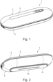
- Fig. 1
- eine Ansicht von schräg oben auf die erfindungsgemäße Plasma-Vorrichtung,
- Fig. 2
- eine Ansicht von schräg unten auf die erfindungsgemäße Plasma-Vorrichtung,
- Fig. 3
- eine Schnittdarstellung durch eine erfindungsgemäße Plasma-Vorrichtung bei geschlossenem Gehäuse,
- Fig. 4
- eine Darstellung wie in
Fig. 3 , jedoch bei einem geöffneten Gehäuse, bei welchem die Oberschale um einen Winkel α von 5° zur Unterschale aufgeschwenkt ist, - Fig. 5
- eine Darstellung wie in
Fig. 4 , jedoch bei weiter aufgeschwenkter Oberschale, - Fig. 6
- eine Detaildarstellung aus
Fig. 3 im Bereich einer Schwenkachse, - Fig. 7
- eine Detaildarstellung aus
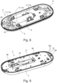
Fig. 5 , - Fig. 8
- eine Ansicht von innen auf die Oberschale,
- Fig. 9
- eine Ansicht von innen auf die Unterschale.
- Entsprechend den
Fig. 1 bis 7 , weist eine erfindungsgemäße Plasma-Vorrichtung 1 zum Behandeln von Oberflächen, beispielsweise zum Auffrischen von Textilien, ein Gehäuse 2 mit einer Unterschale 3 sowie einer schwenkbar daran gelagerten Oberschale 4 auf. In der Oberschale 4 ist dabei eine Aufnahme 5 für einen elektrischen Energiespeicher 6, beispielsweise einen Akkumulator oder eine Batterie, vorgesehen, während in der Unterschale 3 eine Plasmaquelle 7 sowie eine Elektronikeinrichtung 8 mit elektrischen Kontaktelementen 9a und 9b angeordnet ist. Die Elektronikeinrichtung 8 kann dabei beispielsweise als Platine ausgebildet sein und zur Steuerung der Plasmaquelle 7 dienen. Betrachtet man nun die Plasma-Vorrichtung 1 entsprechend derFig. 3 , so kann man erkennen, dass bei einem geschlossenen Gehäuse 2, das heißt bei direkt auf der Unterschale 3 aufliegender Oberschale 4, die elektrischen Kontaktelemente 9a, 9b mit entsprechenden Polen des elektrischen Energiespeichers 6 verbunden sind und dadurch die Elektronikeinrichtung 8 bzw. die Plasmaquelle 7 elektrisch mit dem Energiespeicher 6 verbunden sind. - Wird nun das Gehäuse 2 geöffnet, indem die Oberschale 4 relativ zur Unterschale 3 um eine Schwenkachse 10 aufgeschwenkt wird, so verliert das elektrische Kontaktelement 9a der Elektronikeinrichtung 8 ab einem vordefinierten Öffnungswinkel α ≥ 5° den Kontakt zum elektrischen Energiespeicher 6, wodurch die Spannungsversorgung der Elektronikeinrichtung 8 und damit auch der Plasmaquelle 7 unterbrochen wird. Diese Situation ist gemäß der
Fig. 4 dargestellt. Gemäß derFig. 4 ist genau der Öffnungszustand des Gehäuses 2 gezeigt, bei dem das Kontaktelement 9a gerade noch mit dem Energiespeicher 6 in Verbindung steht. Bei einem Öffnungswinkel α von ca. 5° beträgt ein maximaler Abstand d der Oberschale 4 von der Unterschale 3 ca. 14 mm. Der maximale Abstand d wird dabei auf der der Schwenkachse 10 gegenüberliegenden Seite der Plasma-Vorrichtung 1 abgelesen. Der Öffnungswinkel α liegt dabei in der Blattebene, das heißt in einer vertikalen Längsebene bezogen auf die Plasma-Vorrichtung 1. - Wird die Oberschale 4 weiter aufgeschwenkt, wie dies gemäß der
Fig. 5 gezeigt ist, so verliert auch das Kontaktelement 9b den Kontakt zum elektrischen Energiespeicher 6, wodurch dieser elektrisch komplett isoliert von den Kontaktelementen 9a und 9b ist. Der elektrische Energiespeicher 6 ist dabei in der Aufnahme 5 der Oberschale 4 fixiert, so dass durch ein komplettes Aufklappen der Oberschale 4 der elektrische Energiespeicher 6 einfach von oben in die Aufnahme 5 eingedrückt bzw. wieder aus dieser herausgezogen werden kann. Über entsprechende Halteelemente 17, beispielsweise Klemmelemente, wird der elektrische Energiespeicher 6 auch bei nach unten offener Aufnahme 5, wie diese gemäß denFig. 3 bis 5 undFig. 8 dargestellt ist, zuverlässig gehalten. Betrachtet man dieFig. 8 genauer, so kann man erkennen, dass hier an einem Längsende der Aufnahme 5 Halteelemente 17, 17a vorgesehen sind, die den elektrischen Energiespeicher 6 sowohl an seinem Umfang umfassen als auch an seiner Stirnseite 18. Die Halteelemente 17a bilden somit eine Art Schuh für den Energiespeicher 6. Die anderen Halteelemente 17 sind als federnde Klemmelemente 17b ausgebildet und spannen den Energiespeicher 6 in die Aufnahme 5 vor. - Bei geschlossenem Gehäuse 2 greift der elektrische Energiespeicher 6 in eine entsprechende Ausnehmung 19 der Elektronikeinrichtung 8, beispielsweise der Platine, ein. In
Fig. 4 ist zusätzlich eine optionale Schutzwand 16 eingezeichnet, die den Energiespeicher 6 schützt und beispielsweise durch Eingreifen in eine zugehörige Öffnung an der Elektronikeinrichtung 8 eine Aussteifung bewirkt. Weiter ist eine direkte Berührung der Kontaktfläche des Energiespeichers 6 mit nadelartigen Gegenständen von der Öffnungsseite her erschwert. - Mit der erfindungsgemäßen Plasma-Vorrichtung 1 kann sichergestellt werden, dass bei einem Öffnen des Gehäuses 2 eine zuverlässige Spannungsunterbrechung an der Elektronikeinrichtung 8 und der Plasmaquelle 7 gewährleistet werden kann, wodurch insbesondere Spannungs- oder Stromschäden zuverlässig vermieden werden können. Auch kann mit dem erfindungsgemäßen Gehäuse 2 vermieden werden, dass bei einem unbeabsichtigten Herabfallen der Plasma-Vorrichtung 1 und Öffnen des Gehäuses 2 eine weitere Spannungs-/Stromversorgung der Elektronikeinrichtung 8 erfolgt.
- Die Kontaktelemente 9a, 9b können dabei beispielsweise als Federbügel ausgebildet sein und sind dadurch in der Lage, zumindest geringe Einbautoleranzen des Energiespeichers 6 in der Aufnahme 5, ebenso wie Fertigungstoleranzen problemlos zu kompensieren.
- In geschlossenem Zustand des Gehäuses 2 sind die Oberschale 4 und die Unterschale 3 über beispielsweise ein Rastelement 20 (vgl.
Fig. 8 ) oder eine nicht gezeigte Schraube und/oder einen Splint aneinander fixiert, wobei insbesondere das erwähnte Rastelement 20 ein Schließen des Gehäuses 2 ohne weitere Werkzeuge ermöglicht. Durch eine Schraube mit einem entsprechenden Werkzeugeingriff könnte hingegen eine Art Schloss geschaffen werden, welches ein Öffnen der Schraube und damit auch ein Öffnen des Gehäuses 2 ausschließlich mit einem dazu passenden Werkzeug, das heißt einem dazu passenden Schlüssel, ermöglicht. - Betrachtet man die Scharnierfunktion der Oberschale 4 an der Unterschale 3, so kann man erkennen, dass an der Oberschale 4 ein baggerschaufelartiges Element 11 und an der Unterschale 3 eine komplementär dazu ausgebildete Führung 12 angeordnet sind, in der das Element 11 bei einer Schwenkbewegung der Oberschale 4 geführt ist (vgl. auch die
Fig. 8 und 9 ). Durch das Zusammenwirken des Elements 11 mit der Führung 12 kann ein zuverlässiges Aufschwenken der Oberschale 4 relativ zur Unterschale 3 erreicht werden. Im Unterschied zu einem Scharnier, bei welchem die Oberschale 4 drehbar aber ansonsten fest mit der Unterschale 3 verbunden ist, ermöglicht die Lösung mit dem Element 11 und der Führung 12 ein weites Aufklappen der Oberschale 4 sowie auch ein Abnehmen derselben von der Unterschale 3. Die Führung 12 besitzt dabei vorzugsweise zwei kreissegmentartige äußere Führungskonturen 12a sowie eine dazwischen angeordnete innere Führungskontur 12b, über welche das Element 11 sowohl an einer Außenseite als auch an einer Innenseite geführt ist. - In der Oberschale 4 des Gehäuses 2 sind dabei vorzugsweise keine Elektronikkomponenten verbaut, so dass diese lediglich als oberer Abschluss des Gehäuses 2 und zur Aufnahme des elektrischen Energiespeichers 6 dient.
- Um darüber hinaus eine möglichst hohe Reinigungsleistung der Plasma-Vorrichtung 1 zu erzielen, ist an der Unterschale 3 eine in Längsrichtung 13 des Gehäuses 2 verlaufende Plateaufläche 14 mit zumindest einer Elektrode 15 vorgesehen, über die Plasma erzeugbar bzw. auf die zu behandelnde Oberfläche ausbringbar ist (vgl.
Fig. 2 bis 5 ). Die Plateaufläche 14 ist dabei vorzugsweise federbeaufschlagt und steht in einem Nichtgebrauchszustand der Plasma-Vorrichtung 1 (vgl. dieFig. 2 bis 5 ) über das Gehäuse 2, das heißt in diesem Fall über die Unterschale 3 nach unten über. Durch die Federbeaufschlagung der Plateaufläche 14 ist es möglich, diese während der Nutzung der Plasma-Vorrichtung 1 dicht auf der zu reinigenden bzw. aufzufrischenden Oberfläche entlang zu fahren, wodurch insbesondere eine übermäßige Ozonproduktion durch die Plasmaquelle 7 verhindert werden kann. Hierdurch lassen sich sowohl Atemwegsreizungen als auch unerwünschte Ver- bzw. Entfärbungen der zu reinigenden Oberfläche durch eine zu starke Ozonkonzentration verhindern. - Mit der erfindungsgemäßen Plasma-Vorrichtung 1 ist es möglich, eine leichte Zugänglichkeit für Wartungs- und Reparaturzwecke zu schaffen und zugleich gewährleisten, dass die Plasma-Vorrichtung 1 ab einem vordefinierten Öffnungsgrad des Gehäuses 2 vom elektrischen Energiespeicher 6 isoliert und damit stromlos geschalten ist.
-
- 1
- Plasma-Vorrichtung
- 2
- Gehäuse
- 3
- Unterschale
- 4
- Oberschale
- 5
- Aufnahme
- 6
- Energiespeicher
- 7
- Plasmaquelle
- 8
- Elektronikeinrichtung
- 9
- Kontaktelemente
- 10
- Schwenkachse
- 11
- Element
- 12
- Führung
- 13
- Längsrichtung
- 14
- Plateaufläche
- 15
- Elektrode
- 16
- Schutzwand
- 17
- Halteelement
- 18
- Stirnseite des Energiespeichers
- 19
- Ausnehmung
- 20
- Rastelement
Claims (10)
- Plasma-Vorrichtung (1) zum Behandeln von Oberflächen, insbesondere bei Textilien, wobei die Plasma-Vorrichtung (1) ein Gehäuse (2) mit einer Unterschale (3) und einer schwenkbar daran gelagerten Oberschale (4) aufweist, wobei in der Oberschale (4) eine Aufnahme (5) für einen elektrischen Energiespeicher (6) vorgesehen ist und wobei in der Unterschale (3) eine Plasmaquelle (7) sowie eine damit verbundene Elektronikeinrichtung (8) mit elektrischen Kontaktelementen (9a, 9b) angeordnet sind, welche bei geschlossenem Gehäuse (2) elektrisch leitend mit dem Energiespeicher (6) verbunden sind und dadurch diesen elektrisch leitend mit der Elektronikeinrichtung (8) verbinden, gekennzeichnet dadurch, dass ab einem Öffnungswinkel α der Oberschale (4) relativ zur Unterschale (3) von α ≥ 5° der Energiespeicher (6) zumindest von einem Kontaktelement (9a, 9b) entkoppelt ist.
- Plasma-Vorrichtung nach Anspruch 1, wobei die Oberschale (4) und die Unterschale (3) in geschlossenem Zustand über ein Rastelement (20) und/oder eine Schraube und/oder einem Splint aneinander fixiert sind.
- Plasma-Vorrichtung nach Anspruch 1 oder 2, wobei bei einem Öffnungswinkel α der Oberschale (4) relativ zur Unterschale (3) von α ≥ 5° ein maximaler Abstand d der Oberschale (4) von der Unterschale (3) ca. 14 mm beträgt.
- Plasma-Vorrichtung nach einem der Ansprüche 1 bis 3, wobei die Kontaktelemente (9a, 9b) als Federbügel ausgebildet sind.
- Plasma-Vorrichtung nach einem der Ansprüche 1 bis 4, wobei an der Oberschale (4) ein baggerschaufelartiges Element (11) und an der Unterschale (3) eine komplementär dazu ausgebildete Führung (12) angeordnet sind, in der das Element (11) bei einer Schwenkbewegung der Oberschale (4) geführt ist.
- Plasma-Vorrichtung nach einem der Ansprüche 1 bis 5, wobei die Oberschale (4) von der Unterschale (3) abnehmbar ist.
- Plasma-Vorrichtung nach einem der vorhergehenden Ansprüche, wobei an der Unterschale (3) eine in Längsrichtung (13) des Gehäuses (2) verlaufende Plateaufläche (14) mit zumindest einer Elektrode (15) vorgesehen ist, über die Plasma auf die zu behandelnde Oberfläche ausbringbar ist, wobei die Plateaufläche (14) federbeaufschlagt ist und in einem Nichtgebrauchszustand der Plasma-Vorrichtung (1) über das Gehäuse (2) übersteht.
- Plasma-Vorrichtung nach einem der vorhergehenden Ansprüche, wobei der Energiespeicher (6) eine Batterie oder ein Akkumulator ist.
- Plasma-Vorrichtung nach einem der vorhergehenden Ansprüche, wobei der Öffnungswinkel α in einer vertikalen Längsebene liegt.
- Plasma-Vorrichtung nach einem der vorhergehenden Ansprüche, wobei an der Oberschale (4) eine Schutzwand angeordnet ist, die in Richtung der Unterschale (3) absteht.
Applications Claiming Priority (1)
| Application Number | Priority Date | Filing Date | Title |
|---|---|---|---|
| DE102020215100.8A DE102020215100A1 (de) | 2020-12-01 | 2020-12-01 | Plasma-Vorrichtung |
Publications (3)
| Publication Number | Publication Date |
|---|---|
| EP4009750A1 EP4009750A1 (de) | 2022-06-08 |
| EP4009750B1 true EP4009750B1 (de) | 2023-11-15 |
| EP4009750C0 EP4009750C0 (de) | 2023-11-15 |
Family
ID=78770415
Family Applications (1)
| Application Number | Title | Priority Date | Filing Date |
|---|---|---|---|
| EP21209794.3A Active EP4009750B1 (de) | 2020-12-01 | 2021-11-23 | Plasma-vorrichtung |
Country Status (2)
| Country | Link |
|---|---|
| EP (1) | EP4009750B1 (de) |
| DE (1) | DE102020215100A1 (de) |
Family Cites Families (8)
| Publication number | Priority date | Publication date | Assignee | Title |
|---|---|---|---|---|
| DE102011100751A1 (de) | 2011-05-05 | 2012-11-08 | Max Planck-Gesellschaft zur Förderung der Wissenschaften e.V. | Verfahren zur Inaktivierung vorzugsweise geruchsrelevanter Moleküle und Vorrichtung zu dessen Durchführung |
| GB201401137D0 (en) * | 2014-01-23 | 2014-03-12 | Linde Aktiengesellshcaft | A nozzle for a plasma generation device |
| CN205814739U (zh) | 2016-05-20 | 2016-12-21 | 金科伟业(中国)有限公司 | 一种便携式灭菌消毒机 |
| DE102017118568B3 (de) * | 2017-08-15 | 2018-10-31 | Cinogy Gmbh | Plasma-Behandlungsgerät |
| DE102018209735A1 (de) | 2018-06-15 | 2019-12-19 | Terraplasma Gmbh | Plasmaeinrichtung zur Behandlung von Körperoberflächen |
| DE102018213143A1 (de) * | 2018-08-06 | 2020-02-06 | Hyve Innovation Design Gmbh | Aktivierungsvorrichtung und Aktivierungsverfahren einer Plasmaquelle zur Oberflächenbehandlung |
| CN108771767A (zh) | 2018-08-24 | 2018-11-09 | 深圳市浪尖开物科技有限公司 | 衣柜净化器 |
| DE102018126492A1 (de) * | 2018-10-24 | 2020-04-30 | Cinogy Gmbh | Plasma-Behandlungsgerät |
-
2020
- 2020-12-01 DE DE102020215100.8A patent/DE102020215100A1/de active Pending
-
2021
- 2021-11-23 EP EP21209794.3A patent/EP4009750B1/de active Active
Also Published As
| Publication number | Publication date |
|---|---|
| DE102020215100A1 (de) | 2022-06-02 |
| EP4009750A1 (de) | 2022-06-08 |
| EP4009750C0 (de) | 2023-11-15 |
Similar Documents
| Publication | Publication Date | Title |
|---|---|---|
| DE10260156A1 (de) | Wäschetrockner und Verwendung eines Ultraschallzerstäubers | |
| WO2009021919A2 (de) | Verfahren zur textilreinigung und desinfektion mittels plasma und plasmaschleuse | |
| EP1352113A1 (de) | Verfahren zum elektrostatischen spinnen von polymeren zum erhalt von nano und mikrofasern | |
| EP4062715B1 (de) | Plasmavorrichtung | |
| DE102012211297B4 (de) | Beduftungsvorrichtung | |
| EP4009750B1 (de) | Plasma-vorrichtung | |
| DE202006020800U1 (de) | Luftdesinfektionsvorrichtung | |
| DE102017112460A1 (de) | Geschirrspülmaschine | |
| DE102022116999A1 (de) | Türverschluss mit Selbstheilung | |
| DE202019002861U1 (de) | Trockendesinfektionseinrichtung für mobile Bediengeräte | |
| DE102020215106A1 (de) | Plasma-Vorrichtung | |
| EP4255511B1 (de) | Plasma-vorrichtung | |
| DE102012111148A1 (de) | Dekontaminationsanordnung sowie Verfahren zum Betreiben einer solchen | |
| DE102009027614A1 (de) | Hausgerät mit einer geprägten Wand | |
| EP2759632A1 (de) | Wäschebehandlungsschrank | |
| WO2022117302A1 (de) | Plasma-vorrichtung | |
| DE102010031108A1 (de) | Vorrichtung und Verfahren zur Aufbereitung von organisch und/oder biologisch verunreinigtem Fluid | |
| DE102020215104B4 (de) | Handgeführtes Gerät mit Hochspannungsleistungselektronik | |
| WO2006122838A1 (de) | Haushaltgerät zur pflege von wäschestücken insbesondere wäschetrockner | |
| DE102013012268A1 (de) | Verfahren und Vorrichtung zur Verbesserung der Raumluft | |
| DE102019110814A1 (de) | Vorrichtung zum Behandeln von Textilien mit einem physikalischen Plasma | |
| EP4009747A1 (de) | Plasma-vorrichtung | |
| DE202006007632U1 (de) | Schrank, insbesondere Sicherheitsschrank | |
| DE202007015765U1 (de) | Desinfektionskammer | |
| WO2006122840A1 (de) | Haushaltgerät zur pflege von wäschestücken, insbesondere wäschetrockner |
Legal Events
| Date | Code | Title | Description |
|---|---|---|---|
| PUAI | Public reference made under article 153(3) epc to a published international application that has entered the european phase |
Free format text: ORIGINAL CODE: 0009012 |
|
| STAA | Information on the status of an ep patent application or granted ep patent |
Free format text: STATUS: THE APPLICATION HAS BEEN PUBLISHED |
|
| AK | Designated contracting states |
Kind code of ref document: A1 Designated state(s): AL AT BE BG CH CY CZ DE DK EE ES FI FR GB GR HR HU IE IS IT LI LT LU LV MC MK MT NL NO PL PT RO RS SE SI SK SM TR |
|
| STAA | Information on the status of an ep patent application or granted ep patent |
Free format text: STATUS: REQUEST FOR EXAMINATION WAS MADE |
|
| 17P | Request for examination filed |
Effective date: 20221208 |
|
| RBV | Designated contracting states (corrected) |
Designated state(s): AL AT BE BG CH CY CZ DE DK EE ES FI FR GB GR HR HU IE IS IT LI LT LU LV MC MK MT NL NO PL PT RO RS SE SI SK SM TR |
|
| GRAP | Despatch of communication of intention to grant a patent |
Free format text: ORIGINAL CODE: EPIDOSNIGR1 |
|
| STAA | Information on the status of an ep patent application or granted ep patent |
Free format text: STATUS: GRANT OF PATENT IS INTENDED |
|
| INTG | Intention to grant announced |
Effective date: 20230616 |
|
| GRAS | Grant fee paid |
Free format text: ORIGINAL CODE: EPIDOSNIGR3 |
|
| GRAA | (expected) grant |
Free format text: ORIGINAL CODE: 0009210 |
|
| STAA | Information on the status of an ep patent application or granted ep patent |
Free format text: STATUS: THE PATENT HAS BEEN GRANTED |
|
| AK | Designated contracting states |
Kind code of ref document: B1 Designated state(s): AL AT BE BG CH CY CZ DE DK EE ES FI FR GB GR HR HU IE IS IT LI LT LU LV MC MK MT NL NO PL PT RO RS SE SI SK SM TR |
|
| REG | Reference to a national code |
Ref country code: CH Ref legal event code: EP Ref country code: GB Ref legal event code: FG4D Free format text: NOT ENGLISH |
|
| REG | Reference to a national code |
Ref country code: DE Ref legal event code: R096 Ref document number: 502021001957 Country of ref document: DE |
|
| REG | Reference to a national code |
Ref country code: IE Ref legal event code: FG4D Free format text: LANGUAGE OF EP DOCUMENT: GERMAN |
|
| U01 | Request for unitary effect filed |
Effective date: 20231213 |
|
| U07 | Unitary effect registered |
Designated state(s): AT BE BG DE DK EE FI FR IT LT LU LV MT NL PT SE SI Effective date: 20231219 |
|
| PG25 | Lapsed in a contracting state [announced via postgrant information from national office to epo] |
Ref country code: GR Free format text: LAPSE BECAUSE OF FAILURE TO SUBMIT A TRANSLATION OF THE DESCRIPTION OR TO PAY THE FEE WITHIN THE PRESCRIBED TIME-LIMIT Effective date: 20240216 |
|
| PG25 | Lapsed in a contracting state [announced via postgrant information from national office to epo] |
Ref country code: IS Free format text: LAPSE BECAUSE OF FAILURE TO SUBMIT A TRANSLATION OF THE DESCRIPTION OR TO PAY THE FEE WITHIN THE PRESCRIBED TIME-LIMIT Effective date: 20240315 |
|
| U20 | Renewal fee for the european patent with unitary effect paid |
Year of fee payment: 3 Effective date: 20240319 |
|
| PG25 | Lapsed in a contracting state [announced via postgrant information from national office to epo] |
Ref country code: ES Free format text: LAPSE BECAUSE OF FAILURE TO SUBMIT A TRANSLATION OF THE DESCRIPTION OR TO PAY THE FEE WITHIN THE PRESCRIBED TIME-LIMIT Effective date: 20231115 |
|
| PG25 | Lapsed in a contracting state [announced via postgrant information from national office to epo] |
Ref country code: IS Free format text: LAPSE BECAUSE OF FAILURE TO SUBMIT A TRANSLATION OF THE DESCRIPTION OR TO PAY THE FEE WITHIN THE PRESCRIBED TIME-LIMIT Effective date: 20240315 Ref country code: GR Free format text: LAPSE BECAUSE OF FAILURE TO SUBMIT A TRANSLATION OF THE DESCRIPTION OR TO PAY THE FEE WITHIN THE PRESCRIBED TIME-LIMIT Effective date: 20240216 Ref country code: ES Free format text: LAPSE BECAUSE OF FAILURE TO SUBMIT A TRANSLATION OF THE DESCRIPTION OR TO PAY THE FEE WITHIN THE PRESCRIBED TIME-LIMIT Effective date: 20231115 |
|
| PG25 | Lapsed in a contracting state [announced via postgrant information from national office to epo] |
Ref country code: RS Free format text: LAPSE BECAUSE OF FAILURE TO SUBMIT A TRANSLATION OF THE DESCRIPTION OR TO PAY THE FEE WITHIN THE PRESCRIBED TIME-LIMIT Effective date: 20231115 Ref country code: PL Free format text: LAPSE BECAUSE OF FAILURE TO SUBMIT A TRANSLATION OF THE DESCRIPTION OR TO PAY THE FEE WITHIN THE PRESCRIBED TIME-LIMIT Effective date: 20231115 Ref country code: NO Free format text: LAPSE BECAUSE OF FAILURE TO SUBMIT A TRANSLATION OF THE DESCRIPTION OR TO PAY THE FEE WITHIN THE PRESCRIBED TIME-LIMIT Effective date: 20240215 Ref country code: HR Free format text: LAPSE BECAUSE OF FAILURE TO SUBMIT A TRANSLATION OF THE DESCRIPTION OR TO PAY THE FEE WITHIN THE PRESCRIBED TIME-LIMIT Effective date: 20231115 |
|
| PG25 | Lapsed in a contracting state [announced via postgrant information from national office to epo] |
Ref country code: CZ Free format text: LAPSE BECAUSE OF FAILURE TO SUBMIT A TRANSLATION OF THE DESCRIPTION OR TO PAY THE FEE WITHIN THE PRESCRIBED TIME-LIMIT Effective date: 20231115 |
|
| PG25 | Lapsed in a contracting state [announced via postgrant information from national office to epo] |
Ref country code: SK Free format text: LAPSE BECAUSE OF FAILURE TO SUBMIT A TRANSLATION OF THE DESCRIPTION OR TO PAY THE FEE WITHIN THE PRESCRIBED TIME-LIMIT Effective date: 20231115 |
|
| PG25 | Lapsed in a contracting state [announced via postgrant information from national office to epo] |
Ref country code: SM Free format text: LAPSE BECAUSE OF FAILURE TO SUBMIT A TRANSLATION OF THE DESCRIPTION OR TO PAY THE FEE WITHIN THE PRESCRIBED TIME-LIMIT Effective date: 20231115 Ref country code: SK Free format text: LAPSE BECAUSE OF FAILURE TO SUBMIT A TRANSLATION OF THE DESCRIPTION OR TO PAY THE FEE WITHIN THE PRESCRIBED TIME-LIMIT Effective date: 20231115 Ref country code: RO Free format text: LAPSE BECAUSE OF FAILURE TO SUBMIT A TRANSLATION OF THE DESCRIPTION OR TO PAY THE FEE WITHIN THE PRESCRIBED TIME-LIMIT Effective date: 20231115 Ref country code: CZ Free format text: LAPSE BECAUSE OF FAILURE TO SUBMIT A TRANSLATION OF THE DESCRIPTION OR TO PAY THE FEE WITHIN THE PRESCRIBED TIME-LIMIT Effective date: 20231115 |
|
| REG | Reference to a national code |
Ref country code: DE Ref legal event code: R097 Ref document number: 502021001957 Country of ref document: DE |
|
| PG25 | Lapsed in a contracting state [announced via postgrant information from national office to epo] |
Ref country code: MC Free format text: LAPSE BECAUSE OF FAILURE TO SUBMIT A TRANSLATION OF THE DESCRIPTION OR TO PAY THE FEE WITHIN THE PRESCRIBED TIME-LIMIT Effective date: 20231115 |
|
| PG25 | Lapsed in a contracting state [announced via postgrant information from national office to epo] |
Ref country code: MC Free format text: LAPSE BECAUSE OF FAILURE TO SUBMIT A TRANSLATION OF THE DESCRIPTION OR TO PAY THE FEE WITHIN THE PRESCRIBED TIME-LIMIT Effective date: 20231115 |
|
| REG | Reference to a national code |
Ref country code: IE Ref legal event code: MM4A |
|
| PLBE | No opposition filed within time limit |
Free format text: ORIGINAL CODE: 0009261 |
|
| STAA | Information on the status of an ep patent application or granted ep patent |
Free format text: STATUS: NO OPPOSITION FILED WITHIN TIME LIMIT |
|
| PG25 | Lapsed in a contracting state [announced via postgrant information from national office to epo] |
Ref country code: IE Free format text: LAPSE BECAUSE OF NON-PAYMENT OF DUE FEES Effective date: 20231123 |
|
| 26N | No opposition filed |
Effective date: 20240819 |
|
| PG25 | Lapsed in a contracting state [announced via postgrant information from national office to epo] |
Ref country code: IE Free format text: LAPSE BECAUSE OF NON-PAYMENT OF DUE FEES Effective date: 20231123 |
|
| U20 | Renewal fee for the european patent with unitary effect paid |
Year of fee payment: 4 Effective date: 20241202 |
|
| REG | Reference to a national code |
Ref country code: CH Ref legal event code: PL |
|
| REG | Reference to a national code |
Ref country code: CH Ref legal event code: PL |
|
| PG25 | Lapsed in a contracting state [announced via postgrant information from national office to epo] |
Ref country code: CH Free format text: LAPSE BECAUSE OF NON-PAYMENT OF DUE FEES Effective date: 20241130 |
|
| PG25 | Lapsed in a contracting state [announced via postgrant information from national office to epo] |
Ref country code: CY Free format text: LAPSE BECAUSE OF FAILURE TO SUBMIT A TRANSLATION OF THE DESCRIPTION OR TO PAY THE FEE WITHIN THE PRESCRIBED TIME-LIMIT; INVALID AB INITIO Effective date: 20211123 |
|
| PG25 | Lapsed in a contracting state [announced via postgrant information from national office to epo] |
Ref country code: TR Free format text: LAPSE BECAUSE OF FAILURE TO SUBMIT A TRANSLATION OF THE DESCRIPTION OR TO PAY THE FEE WITHIN THE PRESCRIBED TIME-LIMIT Effective date: 20231115 |
|
| U20 | Renewal fee for the european patent with unitary effect paid |
Year of fee payment: 5 Effective date: 20251201 |
|
| PG25 | Lapsed in a contracting state [announced via postgrant information from national office to epo] |
Ref country code: HU Free format text: LAPSE BECAUSE OF FAILURE TO SUBMIT A TRANSLATION OF THE DESCRIPTION OR TO PAY THE FEE WITHIN THE PRESCRIBED TIME-LIMIT; INVALID AB INITIO Effective date: 20211123 |