EP4009750B1 - Dispositif plasma - Google Patents
Dispositif plasma Download PDFInfo
- Publication number
- EP4009750B1 EP4009750B1 EP21209794.3A EP21209794A EP4009750B1 EP 4009750 B1 EP4009750 B1 EP 4009750B1 EP 21209794 A EP21209794 A EP 21209794A EP 4009750 B1 EP4009750 B1 EP 4009750B1
- Authority
- EP
- European Patent Office
- Prior art keywords
- upper shell
- plasma
- plasma device
- lower shell
- housing
- Prior art date
- Legal status (The legal status is an assumption and is not a legal conclusion. Google has not performed a legal analysis and makes no representation as to the accuracy of the status listed.)
- Active
Links
Images


Classifications
-
- H—ELECTRICITY
- H05—ELECTRIC TECHNIQUES NOT OTHERWISE PROVIDED FOR
- H05H—PLASMA TECHNIQUE; PRODUCTION OF ACCELERATED ELECTRICALLY-CHARGED PARTICLES OR OF NEUTRONS; PRODUCTION OR ACCELERATION OF NEUTRAL MOLECULAR OR ATOMIC BEAMS
- H05H1/00—Generating plasma; Handling plasma
- H05H1/24—Generating plasma
- H05H1/2406—Generating plasma using dielectric barrier discharges, i.e. with a dielectric interposed between the electrodes
-
- A—HUMAN NECESSITIES
- A61—MEDICAL OR VETERINARY SCIENCE; HYGIENE
- A61L—METHODS OR APPARATUS FOR STERILISING MATERIALS OR OBJECTS IN GENERAL; DISINFECTION, STERILISATION OR DEODORISATION OF AIR; CHEMICAL ASPECTS OF BANDAGES, DRESSINGS, ABSORBENT PADS OR SURGICAL ARTICLES; MATERIALS FOR BANDAGES, DRESSINGS, ABSORBENT PADS OR SURGICAL ARTICLES
- A61L2/00—Disinfection or sterilisation of materials or objects, in general; Accessories therefor
- A61L2/02—Disinfection or sterilisation of materials or objects, in general; Accessories therefor using physical processes
- A61L2/14—Plasma, i.e. ionised gases
-
- D—TEXTILES; PAPER
- D06—TREATMENT OF TEXTILES OR THE LIKE; LAUNDERING; FLEXIBLE MATERIALS NOT OTHERWISE PROVIDED FOR
- D06M—TREATMENT, NOT PROVIDED FOR ELSEWHERE IN CLASS D06, OF FIBRES, THREADS, YARNS, FABRICS, FEATHERS OR FIBROUS GOODS MADE FROM SUCH MATERIALS
- D06M10/00—Physical treatment of fibres, threads, yarns, fabrics or fibrous goods made from such materials, e.g. by ultrasonic waves, corona discharge, irradiation, electric currents or magnetic fields; Physical treatment combined with treatment with chemical compounds or elements
- D06M10/02—Sonic or ultrasonic waves; Corona discharge
- D06M10/025—Corona discharge or low temperature plasma
-
- A—HUMAN NECESSITIES
- A61—MEDICAL OR VETERINARY SCIENCE; HYGIENE
- A61L—METHODS OR APPARATUS FOR STERILISING MATERIALS OR OBJECTS IN GENERAL; DISINFECTION, STERILISATION OR DEODORISATION OF AIR; CHEMICAL ASPECTS OF BANDAGES, DRESSINGS, ABSORBENT PADS OR SURGICAL ARTICLES; MATERIALS FOR BANDAGES, DRESSINGS, ABSORBENT PADS OR SURGICAL ARTICLES
- A61L2103/00—Materials or objects being the target of disinfection or sterilisation
- A61L2103/50—Textiles, e.g. bedwear or towels
-
- A—HUMAN NECESSITIES
- A61—MEDICAL OR VETERINARY SCIENCE; HYGIENE
- A61L—METHODS OR APPARATUS FOR STERILISING MATERIALS OR OBJECTS IN GENERAL; DISINFECTION, STERILISATION OR DEODORISATION OF AIR; CHEMICAL ASPECTS OF BANDAGES, DRESSINGS, ABSORBENT PADS OR SURGICAL ARTICLES; MATERIALS FOR BANDAGES, DRESSINGS, ABSORBENT PADS OR SURGICAL ARTICLES
- A61L2202/00—Aspects relating to methods or apparatus for disinfecting or sterilising materials or objects
- A61L2202/10—Apparatus features
- A61L2202/11—Apparatus for generating biocidal substances, e.g. vaporisers, UV lamps
-
- A—HUMAN NECESSITIES
- A61—MEDICAL OR VETERINARY SCIENCE; HYGIENE
- A61L—METHODS OR APPARATUS FOR STERILISING MATERIALS OR OBJECTS IN GENERAL; DISINFECTION, STERILISATION OR DEODORISATION OF AIR; CHEMICAL ASPECTS OF BANDAGES, DRESSINGS, ABSORBENT PADS OR SURGICAL ARTICLES; MATERIALS FOR BANDAGES, DRESSINGS, ABSORBENT PADS OR SURGICAL ARTICLES
- A61L2202/00—Aspects relating to methods or apparatus for disinfecting or sterilising materials or objects
- A61L2202/10—Apparatus features
- A61L2202/14—Means for controlling sterilisation processes, data processing, presentation and storage means, e.g. sensors, controllers, programs
Definitions
- the present invention relates to a plasma device for treating surfaces, in particular textiles, according to the preamble of claim 1.
- the plasma device for inactivating molecules that are preferably odor-relevant and thus for refreshing surfaces, for example in textiles.
- the plasma device has a housing and an associated plasma source.
- a cleaning device for cleaning clothes is known, with a housing in which a receiving space is provided for receiving a blower. Also provided in the receiving space is a separator which separates an air inlet area from a cleaning area. The areas mentioned are arranged vertically one above the other in the operating state.
- the cleaning device can be used to remove or clean the items of clothing to be treated, in particular from cigarette smoke.
- plasma is referred to as the fourth state of matter. If a sufficient amount of energy is added to a gas or gas mixture, for example in the form of electrical energy, some atoms of the gas are ionized, i.e. electrons are removed from the atomic shell and move as free particles, leaving a positively charged atom behind. If a gas consists of a sufficiently high proportion of free ions and electrons, the state of aggregation is called plasma. Plasma is therefore matter whose components are partially charged components, ions and electrons, which act as free charge carriers move.
- Non-thermal plasma also known as cold plasma
- Non-thermal plasmas are also used in medical technology, for example in the treatment of poorly or non-healing wounds with the help of a so-called plasma pen, using the antimicrobial effect of "cold plasma”.
- the causes of the antibacterial effect of a plasma are heat, drying, shear stress, UV radiation, free radicals and charges.
- heat plays a minor role since these plasmas are operated at room temperature.
- reactive particles are formed, such as various oxygen or nitrogen species, which have a sufficiently long lifespan to damage organic compounds upon indirect exposure. These particles include, among others, atomic oxygen, superoxide radicals, ozone, hydroxyl radicals, nitrogen monoxide and nitrogen dioxide. These particles have a destructive effect on a wide variety of odor components as well as cell components.
- odor components which usually consist of carbon compounds, as well as cell walls of bacteria, germs, viruses, fungi or other comparable microorganisms are exposed directly to the plasma, they become negatively charged due to the bombardment with the electrons present in the plasma. Due to the electrostatic repulsion, this leads to mechanical stress up to the point where the tensile strength is exceeded and the destruction of the odor molecule or the cell wall. But not only mechanical tension due to the charge can destroy the cell walls, but also the disruption of the charge balance of the odor molecules or the cell wall through various other electrostatic interactions and electrolysis, e.g. B. by changing the permeability of the cell walls. A mechanism for inactivating microorganisms also results from the very high-energy ions.
- the plasma can be generated using high frequency. Low-pressure plasmas are therefore particularly suitable for inactivating odors on textile fabrics or on common household surfaces or the like in order to achieve odor activation.
- the surfaces to be treated can be textile materials with natural, plant or animal fibers, such as: B. cotton, sheep's wool, silk, linen, felt or artificial fibers such as. B. nylon.
- the term “surface” should also be understood to include materials and objects made of ceramic, plastic, feathers, leather, glass, wood, or metal.
- a disadvantage of the plasma device known from the prior art is that an energy storage device is installed in such a way that a voltage supply may not be interrupted even when the housing is open. However, this could possibly lead to damage to an electronic unit or the plasma source.
- the present invention is therefore concerned with the problem of providing an improved or at least an alternative embodiment for a plasma device of the generic type, which in particular protects electronic components of the plasma device during maintenance or repair or even in the event of a fall from unwanted electrical Voltage protects.
- the present invention is based on the general idea of equipping a known plasma device for treating surfaces, in particular for refreshing textiles, with a housing with two shells, namely an upper shell and a lower shell, and a power supply for an electronic unit or a plasma source
- the plasma device within the housing must be designed so that it is interrupted if the housing is opened beyond a certain extent.
- the plasma device according to the invention has a housing with a lower shell and an upper shell pivotally mounted thereon, with a receptacle for the electrical energy storage, for example a battery or an accumulator, being provided in the upper shell.
- the plasma source and the electronic device for example a printed circuit board, are located in the lower shell.
- the electronic device has electrical contact elements which are electrically connected to the energy storage when the housing is closed, that is to say when the upper shell is firmly connected to the lower shell, and thereby electrically connect the energy storage to the electronic device and above to the plasma source.
- the voltage supply is interrupted according to the invention, so that the energy storage is no longer electrically conductively connected to the contact elements from the aforementioned opening angle ⁇ . This can ensure that the electronic device, for example a circuit board, is protected from voltage damage, which can be caused, for example, by an unwanted current or an undesirable voltage in the circuit board.
- the variant with an upper shell and a lower shell can be used to create a reliable and cost-effective variant for de-energizing both the electronic device and the plasma source, without the need for additional components such as screws, flaps, snap hooks or the like.
- the power supply of the electronic device and the plasma source coupled to the closed position of the housing of the plasma device also offer the great advantage that if the plasma device falls down and the housing is opened, the electrical energy storage is immediately electrically isolated from the contact elements of the electronic device.
- the housing is usually constructed in such a way that it can open in the event of a fall, thereby interrupting the power supply to the electronic device or the plasma source.
- the opening angle ⁇ preferably extends in a vertical longitudinal plane.
- the upper shell and the lower shell are fixed to one another in the closed state via a locking element and/or a screw and/or a split pin.
- a locking element in particular enabling the housing to be easily closed by, for example, pressing the upper shell against the lower shell without any additional tools.
- the housing can be opened by pushing back the locking element and thus releasing its locking position.
- the upper shell and the lower shell are fixed to one another in the closed state via a screw, such a screw being able to represent a type of lock function, for example via a corresponding head with a corresponding tool engagement, so that the screw can only be unscrewed with a suitably designed tool (key) and the housing is opened can be.
- a split pin can also be provided, which enables simple and user-friendly opening.
- a maximum distance d of the upper shell from the lower shell is expediently approximately 14 mm.
- the distance d is taken at a longitudinal end of the plasma device opposite the pivot axis.
- the contact elements on the electronic device are designed as spring clips.
- Such spring clips enable the contact elements to be preloaded against the poles of the energy storage device, thereby enabling reliable energy transmission.
- the spring clips can also be used to compensate for dimensional or manufacturing tolerances.
- An excavator shovel-like element is expediently arranged on the upper shell and a guide designed to complement it on the lower shell, in which the element is guided during a pivoting movement of the upper shell.
- Such an excavator shovel-like element and a guide designed to complement it enable a pivoting movement of the upper shell relative to the lower shell and at the same time a removal of the upper shell from the lower shell if a predefined opening angle, for example ⁇ > 90 °, is exceeded.
- a predefined opening angle for example ⁇ > 90 °
- a plateau surface running in the longitudinal direction of the housing is expediently provided on the lower shell with at least one electrode, via which plasma can be generated or applied to the surface to be treated, the plateau surface being spring-loaded and protruding beyond the housing when the plasma device is not in use.
- the electrode can also be slightly raised in relation to the plateau surface and, for example, have a line-like shape.
- the electrode can be surrounded by a ceramic substrate.
- the spring-loaded plateau surface also has the effect of shielding the emitted plasma from atmospheric oxygen, so that although sufficient oxygen is available for ozone production, the aforementioned excessive ozone production with the associated disadvantages does not take place.
- the disadvantages of excessive ozone production are, particularly in the case of prolonged exposure to the surface to be treated, for example a textile, discoloration or discoloration of the surface and the risk of respiratory irritation.
- the odor-relevant molecules that can be neutralized with the plasma device according to the invention can be butyric acid, sweat, settled cigarette smoke or general odors that can be perceived as unpleasant.
- the plasma device is based on the fact that the odors are actively eliminated and not unpleasant smells, e.g. B. can be covered up with perfume.
- the plasma device according to the invention can also be used to destroy molecules that are not relevant to odor, such as allergens, protein molecules, prions, etc.
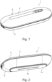
- a plasma device 1 for treating surfaces, for example for refreshing textiles, has a housing 2 with a lower shell 3 and an upper shell 4 pivotally mounted thereon.
- the electronic device 8 can be designed, for example, as a circuit board and serve to control the plasma source 7.
- the electrical contact element 9a of the electronic device 8 loses contact with the electrical energy storage 6 from a predefined opening angle ⁇ ⁇ 5 °, whereby the voltage supply to the Electronic device 8 and thus also the plasma source 7 is interrupted.
- This Situation is according to the Fig. 4 shown.
- the opening state of the housing 2 is shown exactly, in which the contact element 9a is still just connected to the energy storage 6.
- a maximum distance d of the upper shell 4 from the lower shell 3 is approximately 14 mm.
- the maximum distance d is read on the side of the plasma device 1 opposite the pivot axis 10.
- the opening angle ⁇ lies in the plane of the blade, that is, in a vertical longitudinal plane relative to the plasma device 1.
- the contact element 9b also loses contact with the electrical energy storage 6, whereby it is completely electrically isolated from the contact elements 9a and 9b.
- the electrical energy storage 6 is fixed in the receptacle 5 of the upper shell 4, so that by completely opening the upper shell 4, the electrical energy storage 6 can simply be pressed into the receptacle 5 from above or pulled out of it again.
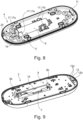
- the electrical energy storage 6 is held using corresponding holding elements 17, for example clamping elements, even when the receptacle 5 is open at the bottom, as shown in FIG Fig. 3 to 5 and Fig. 8 is shown, held reliably. If you look at them Fig.
- holding elements 17, 17a are provided, which encompass the electrical energy storage 6 both on its circumference and on its end face 18.
- the holding elements 17a thus form a kind of shoe for the energy storage 6.
- the other holding elements 17 are designed as resilient clamping elements 17b and bias the energy storage device 6 into the receptacle 5.
- the electrical energy storage 6 engages in a corresponding recess 19 in the electronic device 8, for example the circuit board.
- an optional protective wall 16 is also shown, which protects the energy storage 6 and causes stiffening, for example by engaging in an associated opening on the electronic device 8. Furthermore, direct contact of the contact surface of the energy storage 6 with needle-like objects from the opening side is made more difficult.
- the plasma device 1 With the plasma device 1 according to the invention it can be ensured that when the housing 2 is opened, a reliable voltage interruption occurs at the Electronic device 8 and the plasma source 7 can be guaranteed, whereby voltage or current damage in particular can be reliably avoided. With the housing 2 according to the invention it can also be avoided that if the plasma device 1 accidentally falls and the housing 2 is opened, a further voltage/current supply to the electronic device 8 takes place.
- the contact elements 9a, 9b can be designed, for example, as spring clips and are therefore able to easily compensate for at least small installation tolerances of the energy storage device 6 in the receptacle 5, as well as manufacturing tolerances.
- the upper shell 4 and the lower shell 3 are secured via, for example, a locking element 20 (cf. Fig. 8 ) or a screw (not shown) and/or a cotter pin are fixed together, with the locking element 20 mentioned in particular enabling the housing 2 to be closed without further tools.
- a type of lock could be created, which enables the screw to be opened and thus the housing 2 to be opened exclusively with a suitable tool, that is to say a suitable key.
- the Guide 12 preferably has two circular segment-like outer guide contours 12a and an inner guide contour 12b arranged between them, over which the element 11 is guided on both an outside and an inside.
- a plateau surface 14 running in the longitudinal direction 13 of the housing 2 with at least one electrode 15 is provided on the lower shell 3, via which plasma can be generated or applied to the surface to be treated (see. Fig. 2 to 5 ).
- the plateau surface 14 is preferably spring-loaded and is in a non-use state of the plasma device 1 (cf. the Fig. 2 to 5 ) over the housing 2, that is in this case over the lower shell 3 downwards.
- spring-loading the plateau surface 14 it is possible to move it close to the surface to be cleaned or refreshed while the plasma device 1 is being used, whereby in particular excessive ozone production by the plasma source 7 can be prevented. This can prevent respiratory irritation as well as unwanted discoloration or discoloration of the surface to be cleaned due to excessive ozone concentration.
- the plasma device 1 With the plasma device 1 according to the invention, it is possible to create easy accessibility for maintenance and repair purposes and at the same time to ensure that the plasma device 1 is isolated from the electrical energy storage device 6 from a predefined degree of opening of the housing 2 and is therefore de-energized.
Landscapes
- Engineering & Computer Science (AREA)
- Plasma & Fusion (AREA)
- Physics & Mathematics (AREA)
- Health & Medical Sciences (AREA)
- Life Sciences & Earth Sciences (AREA)
- Epidemiology (AREA)
- Spectroscopy & Molecular Physics (AREA)
- Animal Behavior & Ethology (AREA)
- General Health & Medical Sciences (AREA)
- Public Health (AREA)
- Veterinary Medicine (AREA)
- Textile Engineering (AREA)
- Plasma Technology (AREA)
Claims (10)
- Dispositif à plasma (1) pour traiter des surfaces, en particulier des surfaces de textiles, dans lequel le dispositif à plasma (1) présente un boîtier (2) comprenant une coque inférieure (3) et une coque supérieure (4) montée sur celle-ci de manière pivotante,dans lequel un logement (5) est agencé dans la coque supérieure (4) pour un réservoir d'énergie électrique (6) etune source de plasma (7) ainsi qu'un dispositif électronique (8) relié à celle-ci avec des éléments de contact électriques (9a, 9b) sont disposés dans la coque inférieure (3), lesquels sont reliés de manière électriquement conductrice au réservoir d'énergie (6) lorsque le boîtier (2) est fermé et relient ainsi celui-ci électriquement au dispositif électronique (8),caractérisé en ce qu'à partir d'un angle d'ouverture α de la coque supérieure (4) par rapport à la coque inférieure (3) de α ≥ 5°, le réservoir d'énergie (6) est découplé au moins d'un élément de contact (9a, 9b).
- Dispositif à plasma selon la revendication 1, dans lequel la coque supérieure (4) et la coque inférieure (3) sont fixées l'une à l'autre à l'état fermé par le biais d'un élément d'encliquetage (20) et/ou d'une vis et/ou d'une goupille.
- Dispositif à plasma selon la revendication 1 ou 2, dans lequel, à un angle d'ouverture α de la coque supérieure (4) par rapport à la coque inférieure (3) de α ≥ 5°, une distance maximale d entre la coque supérieure (4) et la coque inférieure (3) est d'environ 14 mm.
- Dispositif à plasma selon l'une des revendications 1 à 3, dans lequel les éléments de contact (9a, 9b) sont réalisés sous forme d'étriers à ressort.
- Dispositif à plasma selon l'une des revendications 1 à 4, dans lequel un élément en forme de godet (11) est disposé sur la coque supérieure (4) et un guide (12) réalisé sous forme complémentaire à celui-ci est disposé sur la coque inférieure (3), dans lequel l'élément (11) est guidé lors d'un mouvement de pivotement de la coque supérieure (4).
- Dispositif à plasma selon l'une des revendications 1 à 5, dans lequel la coque supérieure (4) peut être enlevée de la coque inférieure (3).
- Dispositif à plasma selon l'une des revendications précédentes, dans lequel une surface de plateau (14) s'étendant dans la direction longitudinale (13) du boîtier (2) comprenant au moins une électrode (15) est agencée sur la coque inférieure (3), par laquelle électrode le plasma peut être appliqué sur la surface à traiter,
dans lequel la surface de plateau (14) est sollicitée par un ressort et fait saillie au-delà du boîtier (2) dans un état de non utilisation du dispositif à plasma (1). - Dispositif à plasma selon l'une des revendications précédentes, dans lequel le réservoir d'énergie (6) est une batterie ou un accumulateur.
- Dispositif à plasma selon l'une des revendications précédentes, dans lequel l'angle d'ouverture α se situe dans un plan longitudinal vertical.
- Dispositif à plasma selon l'une des revendications précédentes, dans lequel une paroi de protection est disposée sur la coque supérieure (4), qui s'écarte en direction de la coque inférieure (3).
Applications Claiming Priority (1)
| Application Number | Priority Date | Filing Date | Title |
|---|---|---|---|
| DE102020215100.8A DE102020215100A1 (de) | 2020-12-01 | 2020-12-01 | Plasma-Vorrichtung |
Publications (3)
| Publication Number | Publication Date |
|---|---|
| EP4009750A1 EP4009750A1 (fr) | 2022-06-08 |
| EP4009750B1 true EP4009750B1 (fr) | 2023-11-15 |
| EP4009750C0 EP4009750C0 (fr) | 2023-11-15 |
Family
ID=78770415
Family Applications (1)
| Application Number | Title | Priority Date | Filing Date |
|---|---|---|---|
| EP21209794.3A Active EP4009750B1 (fr) | 2020-12-01 | 2021-11-23 | Dispositif plasma |
Country Status (2)
| Country | Link |
|---|---|
| EP (1) | EP4009750B1 (fr) |
| DE (1) | DE102020215100A1 (fr) |
Family Cites Families (8)
| Publication number | Priority date | Publication date | Assignee | Title |
|---|---|---|---|---|
| DE102011100751A1 (de) | 2011-05-05 | 2012-11-08 | Max Planck-Gesellschaft zur Förderung der Wissenschaften e.V. | Verfahren zur Inaktivierung vorzugsweise geruchsrelevanter Moleküle und Vorrichtung zu dessen Durchführung |
| GB201401137D0 (en) * | 2014-01-23 | 2014-03-12 | Linde Aktiengesellshcaft | A nozzle for a plasma generation device |
| CN205814739U (zh) | 2016-05-20 | 2016-12-21 | 金科伟业(中国)有限公司 | 一种便携式灭菌消毒机 |
| DE102017118568B3 (de) * | 2017-08-15 | 2018-10-31 | Cinogy Gmbh | Plasma-Behandlungsgerät |
| DE102018209735A1 (de) | 2018-06-15 | 2019-12-19 | Terraplasma Gmbh | Plasmaeinrichtung zur Behandlung von Körperoberflächen |
| DE102018213143A1 (de) * | 2018-08-06 | 2020-02-06 | Hyve Innovation Design Gmbh | Aktivierungsvorrichtung und Aktivierungsverfahren einer Plasmaquelle zur Oberflächenbehandlung |
| CN108771767A (zh) | 2018-08-24 | 2018-11-09 | 深圳市浪尖开物科技有限公司 | 衣柜净化器 |
| DE102018126492A1 (de) * | 2018-10-24 | 2020-04-30 | Cinogy Gmbh | Plasma-Behandlungsgerät |
-
2020
- 2020-12-01 DE DE102020215100.8A patent/DE102020215100A1/de active Pending
-
2021
- 2021-11-23 EP EP21209794.3A patent/EP4009750B1/fr active Active
Also Published As
| Publication number | Publication date |
|---|---|
| DE102020215100A1 (de) | 2022-06-02 |
| EP4009750A1 (fr) | 2022-06-08 |
| EP4009750C0 (fr) | 2023-11-15 |
Similar Documents
| Publication | Publication Date | Title |
|---|---|---|
| DE10260156A1 (de) | Wäschetrockner und Verwendung eines Ultraschallzerstäubers | |
| WO2009021919A2 (fr) | Procédé de nettoyage et désinfection de textiles par plasma et sas à plasma | |
| EP1352113A1 (fr) | Procede de filage electrostatique de polymeres permettant d'obtenir des nanofibres et des microfibres | |
| EP4062715B1 (fr) | Dispositif à plasma | |
| DE102012211297B4 (de) | Beduftungsvorrichtung | |
| EP4009750B1 (fr) | Dispositif plasma | |
| DE202006020800U1 (de) | Luftdesinfektionsvorrichtung | |
| DE102017112460A1 (de) | Geschirrspülmaschine | |
| DE102022116999A1 (de) | Türverschluss mit Selbstheilung | |
| DE202019002861U1 (de) | Trockendesinfektionseinrichtung für mobile Bediengeräte | |
| DE102020215106A1 (de) | Plasma-Vorrichtung | |
| EP4255511B1 (fr) | Dispositif à plasma | |
| DE102012111148A1 (de) | Dekontaminationsanordnung sowie Verfahren zum Betreiben einer solchen | |
| DE102009027614A1 (de) | Hausgerät mit einer geprägten Wand | |
| EP2759632A1 (fr) | Armoire de traitement du linge | |
| WO2022117302A1 (fr) | Dispositif à plasma | |
| DE102010031108A1 (de) | Vorrichtung und Verfahren zur Aufbereitung von organisch und/oder biologisch verunreinigtem Fluid | |
| DE102020215104B4 (de) | Handgeführtes Gerät mit Hochspannungsleistungselektronik | |
| WO2006122838A1 (fr) | Appareil menager pour entretenir du linge, notamment seche-linge | |
| DE102013012268A1 (de) | Verfahren und Vorrichtung zur Verbesserung der Raumluft | |
| DE102019110814A1 (de) | Vorrichtung zum Behandeln von Textilien mit einem physikalischen Plasma | |
| EP4009747A1 (fr) | Dispositif plasma | |
| DE202006007632U1 (de) | Schrank, insbesondere Sicherheitsschrank | |
| DE202007015765U1 (de) | Desinfektionskammer | |
| WO2006122840A1 (fr) | Appareil electromenager destine a l'entretien du linge, en particulier seche-linge |
Legal Events
| Date | Code | Title | Description |
|---|---|---|---|
| PUAI | Public reference made under article 153(3) epc to a published international application that has entered the european phase |
Free format text: ORIGINAL CODE: 0009012 |
|
| STAA | Information on the status of an ep patent application or granted ep patent |
Free format text: STATUS: THE APPLICATION HAS BEEN PUBLISHED |
|
| AK | Designated contracting states |
Kind code of ref document: A1 Designated state(s): AL AT BE BG CH CY CZ DE DK EE ES FI FR GB GR HR HU IE IS IT LI LT LU LV MC MK MT NL NO PL PT RO RS SE SI SK SM TR |
|
| STAA | Information on the status of an ep patent application or granted ep patent |
Free format text: STATUS: REQUEST FOR EXAMINATION WAS MADE |
|
| 17P | Request for examination filed |
Effective date: 20221208 |
|
| RBV | Designated contracting states (corrected) |
Designated state(s): AL AT BE BG CH CY CZ DE DK EE ES FI FR GB GR HR HU IE IS IT LI LT LU LV MC MK MT NL NO PL PT RO RS SE SI SK SM TR |
|
| GRAP | Despatch of communication of intention to grant a patent |
Free format text: ORIGINAL CODE: EPIDOSNIGR1 |
|
| STAA | Information on the status of an ep patent application or granted ep patent |
Free format text: STATUS: GRANT OF PATENT IS INTENDED |
|
| INTG | Intention to grant announced |
Effective date: 20230616 |
|
| GRAS | Grant fee paid |
Free format text: ORIGINAL CODE: EPIDOSNIGR3 |
|
| GRAA | (expected) grant |
Free format text: ORIGINAL CODE: 0009210 |
|
| STAA | Information on the status of an ep patent application or granted ep patent |
Free format text: STATUS: THE PATENT HAS BEEN GRANTED |
|
| AK | Designated contracting states |
Kind code of ref document: B1 Designated state(s): AL AT BE BG CH CY CZ DE DK EE ES FI FR GB GR HR HU IE IS IT LI LT LU LV MC MK MT NL NO PL PT RO RS SE SI SK SM TR |
|
| REG | Reference to a national code |
Ref country code: CH Ref legal event code: EP Ref country code: GB Ref legal event code: FG4D Free format text: NOT ENGLISH |
|
| REG | Reference to a national code |
Ref country code: DE Ref legal event code: R096 Ref document number: 502021001957 Country of ref document: DE |
|
| REG | Reference to a national code |
Ref country code: IE Ref legal event code: FG4D Free format text: LANGUAGE OF EP DOCUMENT: GERMAN |
|
| U01 | Request for unitary effect filed |
Effective date: 20231213 |
|
| U07 | Unitary effect registered |
Designated state(s): AT BE BG DE DK EE FI FR IT LT LU LV MT NL PT SE SI Effective date: 20231219 |
|
| PG25 | Lapsed in a contracting state [announced via postgrant information from national office to epo] |
Ref country code: GR Free format text: LAPSE BECAUSE OF FAILURE TO SUBMIT A TRANSLATION OF THE DESCRIPTION OR TO PAY THE FEE WITHIN THE PRESCRIBED TIME-LIMIT Effective date: 20240216 |
|
| PG25 | Lapsed in a contracting state [announced via postgrant information from national office to epo] |
Ref country code: IS Free format text: LAPSE BECAUSE OF FAILURE TO SUBMIT A TRANSLATION OF THE DESCRIPTION OR TO PAY THE FEE WITHIN THE PRESCRIBED TIME-LIMIT Effective date: 20240315 |
|
| U20 | Renewal fee for the european patent with unitary effect paid |
Year of fee payment: 3 Effective date: 20240319 |
|
| PG25 | Lapsed in a contracting state [announced via postgrant information from national office to epo] |
Ref country code: ES Free format text: LAPSE BECAUSE OF FAILURE TO SUBMIT A TRANSLATION OF THE DESCRIPTION OR TO PAY THE FEE WITHIN THE PRESCRIBED TIME-LIMIT Effective date: 20231115 |
|
| PG25 | Lapsed in a contracting state [announced via postgrant information from national office to epo] |
Ref country code: IS Free format text: LAPSE BECAUSE OF FAILURE TO SUBMIT A TRANSLATION OF THE DESCRIPTION OR TO PAY THE FEE WITHIN THE PRESCRIBED TIME-LIMIT Effective date: 20240315 Ref country code: GR Free format text: LAPSE BECAUSE OF FAILURE TO SUBMIT A TRANSLATION OF THE DESCRIPTION OR TO PAY THE FEE WITHIN THE PRESCRIBED TIME-LIMIT Effective date: 20240216 Ref country code: ES Free format text: LAPSE BECAUSE OF FAILURE TO SUBMIT A TRANSLATION OF THE DESCRIPTION OR TO PAY THE FEE WITHIN THE PRESCRIBED TIME-LIMIT Effective date: 20231115 |
|
| PG25 | Lapsed in a contracting state [announced via postgrant information from national office to epo] |
Ref country code: RS Free format text: LAPSE BECAUSE OF FAILURE TO SUBMIT A TRANSLATION OF THE DESCRIPTION OR TO PAY THE FEE WITHIN THE PRESCRIBED TIME-LIMIT Effective date: 20231115 Ref country code: PL Free format text: LAPSE BECAUSE OF FAILURE TO SUBMIT A TRANSLATION OF THE DESCRIPTION OR TO PAY THE FEE WITHIN THE PRESCRIBED TIME-LIMIT Effective date: 20231115 Ref country code: NO Free format text: LAPSE BECAUSE OF FAILURE TO SUBMIT A TRANSLATION OF THE DESCRIPTION OR TO PAY THE FEE WITHIN THE PRESCRIBED TIME-LIMIT Effective date: 20240215 Ref country code: HR Free format text: LAPSE BECAUSE OF FAILURE TO SUBMIT A TRANSLATION OF THE DESCRIPTION OR TO PAY THE FEE WITHIN THE PRESCRIBED TIME-LIMIT Effective date: 20231115 |
|
| PG25 | Lapsed in a contracting state [announced via postgrant information from national office to epo] |
Ref country code: CZ Free format text: LAPSE BECAUSE OF FAILURE TO SUBMIT A TRANSLATION OF THE DESCRIPTION OR TO PAY THE FEE WITHIN THE PRESCRIBED TIME-LIMIT Effective date: 20231115 |
|
| PG25 | Lapsed in a contracting state [announced via postgrant information from national office to epo] |
Ref country code: SK Free format text: LAPSE BECAUSE OF FAILURE TO SUBMIT A TRANSLATION OF THE DESCRIPTION OR TO PAY THE FEE WITHIN THE PRESCRIBED TIME-LIMIT Effective date: 20231115 |
|
| PG25 | Lapsed in a contracting state [announced via postgrant information from national office to epo] |
Ref country code: SM Free format text: LAPSE BECAUSE OF FAILURE TO SUBMIT A TRANSLATION OF THE DESCRIPTION OR TO PAY THE FEE WITHIN THE PRESCRIBED TIME-LIMIT Effective date: 20231115 Ref country code: SK Free format text: LAPSE BECAUSE OF FAILURE TO SUBMIT A TRANSLATION OF THE DESCRIPTION OR TO PAY THE FEE WITHIN THE PRESCRIBED TIME-LIMIT Effective date: 20231115 Ref country code: RO Free format text: LAPSE BECAUSE OF FAILURE TO SUBMIT A TRANSLATION OF THE DESCRIPTION OR TO PAY THE FEE WITHIN THE PRESCRIBED TIME-LIMIT Effective date: 20231115 Ref country code: CZ Free format text: LAPSE BECAUSE OF FAILURE TO SUBMIT A TRANSLATION OF THE DESCRIPTION OR TO PAY THE FEE WITHIN THE PRESCRIBED TIME-LIMIT Effective date: 20231115 |
|
| REG | Reference to a national code |
Ref country code: DE Ref legal event code: R097 Ref document number: 502021001957 Country of ref document: DE |
|
| PG25 | Lapsed in a contracting state [announced via postgrant information from national office to epo] |
Ref country code: MC Free format text: LAPSE BECAUSE OF FAILURE TO SUBMIT A TRANSLATION OF THE DESCRIPTION OR TO PAY THE FEE WITHIN THE PRESCRIBED TIME-LIMIT Effective date: 20231115 |
|
| PG25 | Lapsed in a contracting state [announced via postgrant information from national office to epo] |
Ref country code: MC Free format text: LAPSE BECAUSE OF FAILURE TO SUBMIT A TRANSLATION OF THE DESCRIPTION OR TO PAY THE FEE WITHIN THE PRESCRIBED TIME-LIMIT Effective date: 20231115 |
|
| REG | Reference to a national code |
Ref country code: IE Ref legal event code: MM4A |
|
| PLBE | No opposition filed within time limit |
Free format text: ORIGINAL CODE: 0009261 |
|
| STAA | Information on the status of an ep patent application or granted ep patent |
Free format text: STATUS: NO OPPOSITION FILED WITHIN TIME LIMIT |
|
| PG25 | Lapsed in a contracting state [announced via postgrant information from national office to epo] |
Ref country code: IE Free format text: LAPSE BECAUSE OF NON-PAYMENT OF DUE FEES Effective date: 20231123 |
|
| 26N | No opposition filed |
Effective date: 20240819 |
|
| PG25 | Lapsed in a contracting state [announced via postgrant information from national office to epo] |
Ref country code: IE Free format text: LAPSE BECAUSE OF NON-PAYMENT OF DUE FEES Effective date: 20231123 |
|
| U20 | Renewal fee for the european patent with unitary effect paid |
Year of fee payment: 4 Effective date: 20241202 |
|
| REG | Reference to a national code |
Ref country code: CH Ref legal event code: PL |
|
| REG | Reference to a national code |
Ref country code: CH Ref legal event code: PL |
|
| PG25 | Lapsed in a contracting state [announced via postgrant information from national office to epo] |
Ref country code: CH Free format text: LAPSE BECAUSE OF NON-PAYMENT OF DUE FEES Effective date: 20241130 |
|
| PG25 | Lapsed in a contracting state [announced via postgrant information from national office to epo] |
Ref country code: CY Free format text: LAPSE BECAUSE OF FAILURE TO SUBMIT A TRANSLATION OF THE DESCRIPTION OR TO PAY THE FEE WITHIN THE PRESCRIBED TIME-LIMIT; INVALID AB INITIO Effective date: 20211123 |
|
| PG25 | Lapsed in a contracting state [announced via postgrant information from national office to epo] |
Ref country code: TR Free format text: LAPSE BECAUSE OF FAILURE TO SUBMIT A TRANSLATION OF THE DESCRIPTION OR TO PAY THE FEE WITHIN THE PRESCRIBED TIME-LIMIT Effective date: 20231115 |
|
| U20 | Renewal fee for the european patent with unitary effect paid |
Year of fee payment: 5 Effective date: 20251201 |
|
| PG25 | Lapsed in a contracting state [announced via postgrant information from national office to epo] |
Ref country code: HU Free format text: LAPSE BECAUSE OF FAILURE TO SUBMIT A TRANSLATION OF THE DESCRIPTION OR TO PAY THE FEE WITHIN THE PRESCRIBED TIME-LIMIT; INVALID AB INITIO Effective date: 20211123 |