EP4009887B1 - Système de réparation de fracture de l'acromion - Google Patents
Système de réparation de fracture de l'acromion Download PDFInfo
- Publication number
- EP4009887B1 EP4009887B1 EP20850069.4A EP20850069A EP4009887B1 EP 4009887 B1 EP4009887 B1 EP 4009887B1 EP 20850069 A EP20850069 A EP 20850069A EP 4009887 B1 EP4009887 B1 EP 4009887B1
- Authority
- EP
- European Patent Office
- Prior art keywords
- plate
- hook
- scapula
- acromion
- scapular
- Prior art date
- Legal status (The legal status is an assumption and is not a legal conclusion. Google has not performed a legal analysis and makes no representation as to the accuracy of the status listed.)
- Active
Links
Images








Classifications
-
- A—HUMAN NECESSITIES
- A61—MEDICAL OR VETERINARY SCIENCE; HYGIENE
- A61B—DIAGNOSIS; SURGERY; IDENTIFICATION
- A61B17/00—Surgical instruments, devices or methods
- A61B17/56—Surgical instruments or methods for treatment of bones or joints; Devices specially adapted therefor
- A61B17/58—Surgical instruments or methods for treatment of bones or joints; Devices specially adapted therefor for osteosynthesis, e.g. bone plates, screws or setting implements
- A61B17/68—Internal fixation devices, including fasteners and spinal fixators, even if a part thereof projects from the skin
- A61B17/80—Cortical plates, i.e. bone plates; Instruments for holding or positioning cortical plates, or for compressing bones attached to cortical plates
- A61B17/8061—Cortical plates, i.e. bone plates; Instruments for holding or positioning cortical plates, or for compressing bones attached to cortical plates specially adapted for particular bones
-
- A—HUMAN NECESSITIES
- A61—MEDICAL OR VETERINARY SCIENCE; HYGIENE
- A61B—DIAGNOSIS; SURGERY; IDENTIFICATION
- A61B17/00—Surgical instruments, devices or methods
- A61B17/56—Surgical instruments or methods for treatment of bones or joints; Devices specially adapted therefor
- A61B17/58—Surgical instruments or methods for treatment of bones or joints; Devices specially adapted therefor for osteosynthesis, e.g. bone plates, screws or setting implements
- A61B17/68—Internal fixation devices, including fasteners and spinal fixators, even if a part thereof projects from the skin
- A61B17/80—Cortical plates, i.e. bone plates; Instruments for holding or positioning cortical plates, or for compressing bones attached to cortical plates
- A61B17/8004—Cortical plates, i.e. bone plates; Instruments for holding or positioning cortical plates, or for compressing bones attached to cortical plates with means for distracting or compressing the bone or bones
-
- A—HUMAN NECESSITIES
- A61—MEDICAL OR VETERINARY SCIENCE; HYGIENE
- A61B—DIAGNOSIS; SURGERY; IDENTIFICATION
- A61B17/00—Surgical instruments, devices or methods
- A61B17/56—Surgical instruments or methods for treatment of bones or joints; Devices specially adapted therefor
- A61B17/58—Surgical instruments or methods for treatment of bones or joints; Devices specially adapted therefor for osteosynthesis, e.g. bone plates, screws or setting implements
- A61B17/68—Internal fixation devices, including fasteners and spinal fixators, even if a part thereof projects from the skin
- A61B17/80—Cortical plates, i.e. bone plates; Instruments for holding or positioning cortical plates, or for compressing bones attached to cortical plates
- A61B17/8085—Cortical plates, i.e. bone plates; Instruments for holding or positioning cortical plates, or for compressing bones attached to cortical plates with pliable or malleable elements or having a mesh-like structure, e.g. small strips
-
- A—HUMAN NECESSITIES
- A61—MEDICAL OR VETERINARY SCIENCE; HYGIENE
- A61B—DIAGNOSIS; SURGERY; IDENTIFICATION
- A61B17/00—Surgical instruments, devices or methods
- A61B17/56—Surgical instruments or methods for treatment of bones or joints; Devices specially adapted therefor
- A61B17/58—Surgical instruments or methods for treatment of bones or joints; Devices specially adapted therefor for osteosynthesis, e.g. bone plates, screws or setting implements
- A61B17/68—Internal fixation devices, including fasteners and spinal fixators, even if a part thereof projects from the skin
- A61B17/84—Fasteners therefor or fasteners being internal fixation devices
-
- A—HUMAN NECESSITIES
- A61—MEDICAL OR VETERINARY SCIENCE; HYGIENE
- A61B—DIAGNOSIS; SURGERY; IDENTIFICATION
- A61B17/00—Surgical instruments, devices or methods
- A61B17/56—Surgical instruments or methods for treatment of bones or joints; Devices specially adapted therefor
- A61B17/58—Surgical instruments or methods for treatment of bones or joints; Devices specially adapted therefor for osteosynthesis, e.g. bone plates, screws or setting implements
- A61B17/88—Osteosynthesis instruments; Methods or means for implanting or extracting internal or external fixation devices
-
- A—HUMAN NECESSITIES
- A61—MEDICAL OR VETERINARY SCIENCE; HYGIENE
- A61B—DIAGNOSIS; SURGERY; IDENTIFICATION
- A61B17/00—Surgical instruments, devices or methods
- A61B17/16—Instruments for performing osteoclasis; Drills or chisels for bones; Trepans
- A61B17/17—Guides or aligning means for drills, mills, pins or wires
- A61B17/1728—Guides or aligning means for drills, mills, pins or wires for holes for bone plates or plate screws
-
- A—HUMAN NECESSITIES
- A61—MEDICAL OR VETERINARY SCIENCE; HYGIENE
- A61B—DIAGNOSIS; SURGERY; IDENTIFICATION
- A61B17/00—Surgical instruments, devices or methods
- A61B17/16—Instruments for performing osteoclasis; Drills or chisels for bones; Trepans
- A61B17/17—Guides or aligning means for drills, mills, pins or wires
- A61B17/1739—Guides or aligning means for drills, mills, pins or wires specially adapted for particular parts of the body
- A61B17/1778—Guides or aligning means for drills, mills, pins or wires specially adapted for particular parts of the body for the shoulder
-
- A—HUMAN NECESSITIES
- A61—MEDICAL OR VETERINARY SCIENCE; HYGIENE
- A61B—DIAGNOSIS; SURGERY; IDENTIFICATION
- A61B17/00—Surgical instruments, devices or methods
- A61B17/56—Surgical instruments or methods for treatment of bones or joints; Devices specially adapted therefor
- A61B17/58—Surgical instruments or methods for treatment of bones or joints; Devices specially adapted therefor for osteosynthesis, e.g. bone plates, screws or setting implements
- A61B17/68—Internal fixation devices, including fasteners and spinal fixators, even if a part thereof projects from the skin
- A61B17/80—Cortical plates, i.e. bone plates; Instruments for holding or positioning cortical plates, or for compressing bones attached to cortical plates
- A61B17/809—Cortical plates, i.e. bone plates; Instruments for holding or positioning cortical plates, or for compressing bones attached to cortical plates with bone-penetrating elements, e.g. blades or prongs
-
- A—HUMAN NECESSITIES
- A61—MEDICAL OR VETERINARY SCIENCE; HYGIENE
- A61B—DIAGNOSIS; SURGERY; IDENTIFICATION
- A61B17/00—Surgical instruments, devices or methods
- A61B17/56—Surgical instruments or methods for treatment of bones or joints; Devices specially adapted therefor
- A61B2017/568—Surgical instruments or methods for treatment of bones or joints; Devices specially adapted therefor produced with shape and dimensions specific for an individual patient
-
- A—HUMAN NECESSITIES
- A61—MEDICAL OR VETERINARY SCIENCE; HYGIENE
- A61B—DIAGNOSIS; SURGERY; IDENTIFICATION
- A61B17/00—Surgical instruments, devices or methods
- A61B17/56—Surgical instruments or methods for treatment of bones or joints; Devices specially adapted therefor
- A61B17/58—Surgical instruments or methods for treatment of bones or joints; Devices specially adapted therefor for osteosynthesis, e.g. bone plates, screws or setting implements
- A61B17/68—Internal fixation devices, including fasteners and spinal fixators, even if a part thereof projects from the skin
- A61B2017/681—Alignment, compression, or distraction mechanisms
Definitions
- the field of invention relates to devices for orthopedic use. More particularly, the field of invention relates to devices for use in the reconstruction of fatigue/insufficiency factures of the acromion and scapula that can occur after reverse total shoulder arthroplasty.
- the document EP 3 135 234 A1 relates to a three-dimensional fracture fixation device for treating clavicle fracture with the intent to protect the supraclavicular nerve from later iatrogenic transsection injury that may occur when the fixation bone plate is removed.
- the components of the three-dimensional fracture fixation device include at least one fixation locking plate, a nerve protection scutum (shield), junctional hooks connecting the fixation locking plate and supporting the nerve protection scutum (shield), and bone screws, which are assembled to form a defined space to accommodate the supraclavicular nerve during open reduction and internal fixation.
- the document EP 1 743 586 A1 relates to a bone plate for use in setting a clavicle, comprising an elongate portion and an arch portion, the elongate portion having a curve approximately the shape of the anterior surface of the clavicle, the arch portion being adapted to fit over a clavicle in the region of the acromial end thereof.
- Reverse total shoulder arthroplasty is a surgical technique in which the shoulder's natural ball-and-socket joint, which has a rounded humeral head (i.e., ball) interfacing with the glenoid cavity (i.e., socket) of the scapula, is replaced by a reversed ball-and-socket joint, which has a glenosphere (i.e., ball) implanted on the shoulder and mating with a cup (i.e., socket) implanted on the humerus.
- rTSA Reverse total shoulder arthroplasty
- FIG. 1A shows a representative radiographic depiction of a shoulder joint after rTSA and prior to scapular fracture
- Figure 1B shows a representative radiographic depiction of the shoulder joint after scapular fracture following rTSA.
- Acromial and scapula fatigue/insufficiency fractures can occur any time after the initial rTSA procedure, occurring as early as the first day of surgery and as late as 10+ years after the surgical procedure.
- Acromial and scapula fatigue/insufficiency fractures after rTSA can occur at various locations on the acromion and scapular spine. These fracture types have been classified as type 1 (fracture of the lateral acromion with a deltoid avulsion), type 2 (fracture of the mid-scapular spine at-or around the location of the scapular notch), and type 3 (fracture at the base of the scapular spine).
- Figures 2A, 2B, and 2C show a superior view, a posterior view, and a superior-oblique view, respectively, of the portions of the acromion that fracture as a result of these different types of fractures.
- Figures 3A and 3B show a superior view and a posterior view, respectively, of a healthy scapula.
- Figures 3C and 3D show a superior view and a posterior view, respectively, of a scapula that has experienced a type 1 fracture.
- Figures 3E and 3F show a superior view and a posterior view, respectively, of a scapula that has experienced a type 2 fracture.
- Figures 3G and 3H show a superior view and a posterior view, respectively, of a scapula that has experienced a type 3 fracture.
- the rate of acromial and scapula fatigue/insufficiency fractures after rTSA is relatively low, but is typically reported to be between 1 and 10%.
- Type 2 fractures appear to be the most common scapular insufficiency fracture type after rTSA.
- the timing and level of rigor of the rehabilitation program may also play a role on the rate and severity of the acromial or scapular fatigue/insufficiency fracture. These fractures could also be caused during the surgery by traction with a retractor when attempting to gain exposure to the glenoid. Whatever the specific cause (or combination of causes), the patient population is predominantly female, osteoporotic, and elderly. As a result of these factors, the fracture is at a disadvantage for healing; patient health quality and patient co-morbidities also influence the quality of fracture reconstruction and the rate and probability of fracture healing over time.
- the present invention relates to a kit as defined by independent claim 1, while preferred embodiments are set forth in the dependent claims. Associated methods are also described herein to aid understanding the invention. These methods do not form part of the claimed invention.
- the invention relates to devices for repair of acromial/scapular fractures.
- the devices described herein are suitable for use to reconstruct the acromion and scapula of rTSA patients who have insufficiency fractures of the acromion or scapula.
- a scapula repair device includes a fracture fixation bone plate (referred to herein as a "plate” for brevity) having a first end, a second end opposite the first end, and at least one fixation point positioned along the plate between the first end and the second end; at least one hook, each of the at least one hook being mounted to a corresponding one of the at least one fixation point of the plate; and at least one fixation element, each of the at least one fixation element being positioned so as to secure a corresponding one of the at least one hook to the corresponding one of the at least one fixation point and to secure the plate to a scapula of a patient, wherein the plate is configured such that, when the plate is secured to the scapula of the patient, the plate extends along at least a portion of a scapular spine of the scapula and at least a portion of an acromion of the scapula, and wherein the plate and the at least one hook
- such retention of the acromion and/or the scapula is suitable to facilitate healing of a fracture, such as a fracture of one of the three different fracture types that occur after rTSA (e.g., as described above with reference to Figures 3A-3H ).
- a kit in an embodiment, includes at least one plate having a first end, a second end opposite the first end, and at least one fixation point positioned along the plate between the first end and the second end, wherein each at least one plate is configured such that, when the at least one plate is secured to a scapula of a patient, at least one the plate extends along at least a portion of a scapular spine of the scapula and at least a portion of an acromion of the spine; a plurality of hooks, each of the plurality of hooks being configured to be secured to a selected one of the at least one fixation point of a selected one of the at least one plate; a plurality of fixation elements, each of the fixation elements being configured to secure a selected one of the plurality of hooks to the selected one of the at least one fixation point of the selected one of the at least one plate and to secure the selected one of the at least one plate to the scapula of the patient, wherein each of the at
- a kit includes at least one plate and a plurality of hooks, wherein each of the at least one plate includes a plurality of fixation points that are spaced apart along each of the at least one plate, wherein the at least one plate includes at least a first plate that is an elongate plate having a first end and a second end opposite the first end, wherein the first plate is sized and shaped so as to be configured to be positioned and to extend along a scapular spine of a scapula of a patient such that the first end is proximate to a trigonum of the scapula and the second end is proximate to an acromion of the scapula and configured to be secured to the scapular spine, wherein each of the hooks is configured to be fixed to a selected one of the fixation points of a selected one of the at least one plate, wherein the plurality of hooks includes at least a first hook including (1) a mount that is configured to be fixed to
- the first plate is contoured so as to conform to the scapular spine.
- At least one of the at least one plate is conformable so as to allow a user to conform the plate to a portion of the scapula.
- the hook portion of the second hook is Y-shaped.
- the first plate, the first hook, and the second hook are configured to cooperate to apply a compression force to a fracture along the scapular spine when (a) the first plate is secured to the scapular spine, (b) the first hook is fixed to the first one of the fixation points of the first plate and positioned such that the first and second hook portions of the first hook extend around the lateral end of the acromion, and (c) the second hook is fixed to the second one of the fixation points of the first plate and positioned such that the hook portion of the second hook extend around the trigonum of the scapula.
- a kit also includes at least one fastener configured to be secured to one of the fixation points of one of the at least one plate the plate and to the scapula so as to secure the one of the at least one plate to the scapula.
- a kit also includes at least one fastener configured to be secured to one of the fixation points of one of the at least one plate and to a selected one of the plurality of hooks so as to secure the selected one of the plurality of hooks to the one of the at least one plate.
- the at least one plate also includes a second plate, wherein the second plate has a first end and a second end opposite the first end of the second plate, wherein the second plate is a curved plate that is sized and shaped so as to be configured to be positioned adjacent to the scapular spine of the patient and the acromion of the patient such that the first end of the second plate is positioned proximate to the trigonum of the patient and the plate extends along the scapular spine of the patient and the acromion of the patient to the second end that is positioned proximate to a top of the acromion of the patient.
- the second hook is sized and shaped so as to be configured so that the hook portion of the second hook extends around the top of the acromion of the patient when the second hook is fixed to one of the fixation points of the second plate that is located proximate to the second end of the second plate.
- the at least one plate includes a second plate that is an elongate plate having a first end and a second end opposite the first end of the second plate, wherein the second plate is sized and shaped so as to be configured to be positioned along the scapular spine and to extend along the scapular spine from the first end that is positioned along an inferior surface of the scapular spine to the second end that is positioned on a posterior surface of the acromion.
- the plurality of hooks includes a third hook including (1) a mount that is configured to be fixed to a selected one of the fixation points of a selected one of the at least one plate, (2) a curved portion extending away from and curving back toward the mount, and (3) a hook portion at an end of the curved portion that is opposite the mount of the second hook, and (4) a fixation hole extending through the hook portion, wherein the fixation hole is configured to receive a fastener so as to fix the hook portion to the scapula.
- the third hook is sized and shaped so as to be configured so that the hook portion extends over a superior surface of the scapular spine when the second plate is positioned along the scapular spine and the second hook is fixed to one of the fixation points of the second plate that is positioned along the inferior surface of the scapular spine.
- the kit also includes a fastener that is configured to be secured in both the mount and the fixation hole of the third hook.
- the fastener is configured to extend through the mount, the scapular spine, and the fixation hole of the third hook when (a) the second plate is positioned along the scapular spine and (b) the third hook is fixed to the one of the fixation points of the second plate that is positioned along the inferior surface of the scapular spine such that the hook portion of the third hook extends over the superior surface of the scapular spine.
- a method includes (1) providing a kit including at least one plate, a plurality of hooks, and a plurality of fasteners; wherein each of the at least one plate includes a plurality of fixation points that are spaced apart along each of the at least one plate, wherein the at least one plate includes at least a first plate that is an elongate plate having a first end and a second end opposite the first end, wherein the first plate is sized and shaped so as to be configured to be positioned and to extend along a scapular spine of a scapula of a patient such that the first end is proximate to a trigonum of the scapula and the second end is proximate to an acromion of the scapula and configured to be secured to the scapular spine, and wherein each of the hooks is configured to be fixed to a selected one of the fixation points of a selected one of the at least one plate, wherein
- an exemplary fracture fixation system restores stability to the shoulder with a fractured acromion and/or scapula through use of a scapular plating system including at least one modular hook that secures around at least one corresponding anatomic scapular feature (e.g., the acromion, the scapular spine, or the scapular trigonum).
- at least one hook is monolithic with a plate (e.g., integrally formed from a single piece of a plate material).
- At least one hook is modularly secured to a plate with a mechanical locking mechanism.
- the plate construct e.g., a plate including at least one integrally formed hook, a plate including at least one modularly attached hook, etc.
- the plate construct can be secured to the scapula with the aid of screws, sutures, wire, and/or pins.
- a plate that is used in connection with at least one modular hook facilitates a simpler surgical technique through a smaller incision while also improving the availability to account for multiple various anatomic size ranges (e.g., by providing modular hooks of various shapes and sizes) to account for the variable scapular anatomy/morphology, thereby reducing the overall scope and kit cost required to account for the anatomical variability required for the global marketplace.
- a plate that is used in connection with at least one modular hook simplifies the manufacturing process and requires lower cost for all the implants in the kit (e.g., by enabling mixing and matching of different configurations).
- a plate that is used in connection with at least one modular hook is able to be placed at morphologically/anatomically strategic locations on a bone, tailored to each patient's individual fracture type (e.g., Type 1, 2, or 3).
- such modular hooks can be placed on the lateral acromion (see, e.g., Figures 5E and 5F ) or directed toward the medial portion of the acromion.
- Figures 5E and 5F also show these holes secured along the medial scapular border, at or around the scapular trigonum.
- modular hooks can be placed along the anterior portion of the acromion (see, e.g., Figures 6E and 6F ) or instead directed toward the posterior portion of the acromion if the orthopedic surgeon/traumatologist deems that location to facilitate the best reconstruction.
- the plate and modular hooks can be secured to the scapular spine, either above the scapular spine, below the scapular spine, or along the side of the scapular spine (see, e.g., Figures 7A-7F ).
- the plate itself is also modular (see, e.g., Figures 8A-8E ) and can also be used in connection with modular hooks.
- such a modular connection can have angular/tilt variability and also variability in rotation and position.
- holes for screw fixation can be positioned at different locations and orientations on the plate to facilitate reconstruction and compression across the fracture lines and the impart additional stability for each of the different fracture types.
- these modular hooks can also accept screws for added fixation (see, e.g., Figures 4C and 4D ).
- numerous holes of various sizes for sutures and wires can be designed to facilitate the reconstruction.
- the sizes of such holes are selected to allow needles of various sizes to easily pass therethrough with the plate compressed against the bone.
- the edges of the suture holes are configured to not abrade a suture when the suture is secured against the plate.
- plates and modular hooks are provided in multiple different sizes and shapes to account for the various acromion and scapula fracture types that the orthopedic surgeon may be presented with after rTSA, namely: type 1, type 2, and type 3 scapular fractures as discussed above.
- the figures accompanying the exemplary embodiments depict multiple views of different design variations of the proposed device to account for the different possible locations of fractures.
- a modular hook may be placed laterally on the acromion, along or around different regions of the acromion, and/or at a different location (e.g., posteriorly, anteriorly, or medially on the scapula, etc.).
- a modular hook may be placed over or under the scapular spine, medially on the scapula at or around the scapular trigonum, and/or at a different location (e.g., posteriorly, anteriorly, or medially on the scapula, etc.).
- plates and modular hooks are provided in multiple different shapes and sizes for each fracture type and are provided in a range of sizes and shapes to account for the normal anatomic variation of the different anatomic morphology of the acromion and scapular spine.
- a n exemplary plate and modular hook may be configured to secure to the top of the scapular spine and acromion and then rotate to the side or undersurface of the scapular spine for additional multi-planar support.
- an exemplary plate may be placed superiorly on the scapular spine and may rotate to the undersurface of the acromion.
- different extensions and shapes are configured or modularly attached to provide multiple various options and positions for screw/suture/wire fixation into the scapula and to gain greater fixation between the bone fragments.
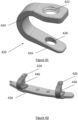
- Figure 4A shows a perspective view of a first hook 400 that may form part of an acromion/scapula fracture repair system.
- the hook 400 is sized and shaped for fixation adjacent the lateral acromion.
- the hook 400 includes a mount 402 that is configured to mount the hook 400 to a plate, a first hook portion 404 proximate the mount 402, a spacer portion 406 extending away from the first hook portion 404, and a second hook portion 408 at the end of the spacer portion 406 opposite the first hook portion 404.
- Figure 4B shows a perspective view of a second hook 410 that may form part of an acromion/scapula fracture repair system.
- the hook 410 is sized and shaped for fixation adjacent the medial scapular blade near the trigonum.
- the hook 410 is sized and shaped for fixation at the top of the acromion.
- the hook 410 includes a mount 412 that is configured to mount the hook 410 to a plate, a curved portion 414 extending away from and curving back toward the mount 412, and a y-shaped hook portion 416 at the end of the curved portion 414 opposite the mount 412.
- Figure 4C shows a perspective view of a third hook 420 that may form part of an acromion/scapula fracture repair system.
- the hook 420 is sized and shaped for fixation along the scapular spine.
- the hook 420 includes a mount 422 that is configured to mount the hook 420 to a plate, a curved portion 424 extending away from and curving back toward the mount 422, a hook portion 426 at the end of the curved portion 424 opposite the mount 422, and a fixation hole 428 extending through the hook portion 426 and configured to receive an attachment element (e.g., a screw) extending therethrough to provide improved fixation.
- an attachment element e.g., a screw
- Figure 4D shows a perspective view of a portion of a plate 430 and two of the third exemplary hook 420.
- a screw 440 secures the hook 420 to the plate 430 by installation through a hole 432 of the plate 430, the mount 422 of the hook 420, and the fixation hole 428 of the hook 420.
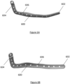
- Figures 5A and 5B shows perspective views of a first plate 500.
- the plate 500 is sized and shaped to be positioned along a scapular spine of a patient.
- the plate 500 includes a first end 502 (e.g., a medial end) and a second end 504 (e.g., a lateral end).
- the plate 500 includes a plurality of fixation points 506 (e.g., holes) extending therethrough and configured to facilitate securing the plate 500 to a bone by mechanical securing devices such as screws, sutures, wire, pins, etc.
- the plate 500 includes ten (10) of the fixation points 506, but it will be apparent to those of skill in the art that this quantity is only exemplary and that the plate 500 may include any number of the fixation points 506.
- Figures 5C and 5D shows a perspective view of the plate 500 as prepared for securing to a scapula of a patient.
- the plate 500 has been prepared by securing one of the second hook 410 to the first end 502 and by securing one of the first hook 400 to the second end 504.
- the first hook 400 and the second hook 410 are secured to the plate 500 by screws 510.
- the combination of the plate 500, the first hook 400, the second hook 410, and the screws 510 is referred to herein as a construct 520.
- Figures 5E and 5F show perspective views of a representative scapula S, with the construct 520 secured thereto.
- Figure 5E shows a posterior view and Figure 5F shows an anterior view.
- the second hook 410 extends around the medial scapular blade near the trigonum
- the plate 500 extends along the scapular spine
- the first hook 400 extends around the lateral acromion.
- the screws 510 extend into the scapula to secure the construct 520 thereto.
- the first hook 400, the plate 500, the second hook 410, and the screws 510 cooperate to retain the acromion in a desired (e.g., anatomically correct) position.
- Figures 6A and 6B show perspective views of a second plate 600.
- the plate 600 is sized, shaped, and curved to extend along a scapular spine and an acromion of a patient.
- the plate 600 includes a first end 602 (e.g., a medial end) and a second end 604 (e.g., a lateral end).
- the plate 600 includes a plurality of fixation points 606 (e.g., holes) extending therethrough and configured to facilitate securing the plate 600 to a bone by mechanical securing devices such as screws, sutures, wire, pins, etc.
- the plate 600 includes thirteen (13) of the fixation points 606, but it will be apparent to those of skill in the art that this quantity is only exemplary and that the plate 600 may include any number of the fixation points 606.
- Figures 6C and 6D show perspective views of the plate 600 as prepared for securing to a scapula of a patient.
- Figure 6C shows a posterior perspective view
- Figure 6D shows an anterior perspective view.
- the plate 600 has been prepared by securing one of the third hook 420 to the second end 604.
- the third hook 420 is secured to the plate 600 by a screw 610.
- the combination of the plate 600, the third hook 420, and the screw 610 is referred to herein as a construct 620.
- Figures 6E and 6F show perspective views of a representative scapula S, with the construct 620 secured thereto.
- Figure 6E shows a posterior view
- Figure 6F shows a lateral view.
- the plate 600 extends along the scapular spine and curves to extend along the acromion
- third hook 420 extends around the top of the acromion.
- the screw 610 extends through the acromion to secure the construct 620 thereto.
- the plate 600, the third hook 420, and the screw 610 cooperate to retain the acromion in a desired (e.g., anatomically correct) position.
- Figure 7A and 7B show perspective views of a third plate 700.
- the plate 700 is curved such that, when the plate 700 is positioned adjacent a scapula of a patient, the first end 702 is positioned along the inferior side of the scapular spine and the second end 704 is positioned along the posterior side of the acromion.
- the plate 700 includes a plurality of fixation points 706 (e.g., holes) extending therethrough and configured to facilitate securing the plate 700 to a bone by mechanical securing devices such as screws, sutures, wire, pins, etc.
- the plate 700 includes eight (8) of the fixation points 706, but it will be apparent to those of skill in the art that this quantity is only exemplary and that the plate 700 may include any number of the fixation points 706.
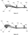
- Figures 7C and 7D show perspective views of the plate 700 as prepared for securing to a scapula of a patient.
- Figure 7C shows a posterior perspective view
- Figure 7D shows an anterior perspective view.
- the plate 700 has been prepared by securing a first one of the third hook 420 to the first end 702, a second one of the third hook 420 intermediate the first and second ends 702, 704, and a third one of the hooks 420 to the second end 704.
- the third hooks 420 are secured to the plate 700 by a screw 710.
- the combination of the plate 700, the third hooks 420, and the screws 710 is referred to herein as a construct 720.
- Figures 7E and 7F show perspective views of a representative scapula S, with the construct 620 secured thereto.
- the plate 700 extends along the inferior side of the scapular spine from the first end 702 of the plate 700 and curves to extend along the posterior of the scapular spine and the posterior of the acromion as it extends toward the second end 704 of the plate 400.
- the first and second ones of the third hooks 420 secure the plate 700 to the scapular spine and the third one of the hooks 420 secures the plate to the acromion.
- the screws 710 extend through the scapular spine and the acromion to secure the construct 710 thereto.
- the plate 700, the hooks 420, and the screws 710 cooperate to retain the acromion in a desired (e.g., anatomically correct) position. thereto.
- the plate 700, the hooks 420, and the screws 710 cooperate to retain the acromion in a desired (e.g., anatomically correct) position.
- Figures 8A and 8B show perspective views of a fourth plate 800.
- the fourth plate 800 is an adjustable plate.
- Figures 8A and 8B show the fourth plate 800 from substantially the same perspective as one another, with the plate 800 shown adjusted in a first position in Figure 8A and in a second position in Figure 8B .
- the plate 800 includes a scapular plate 810, an acromial plate 820, and a modular junction 830 connecting the acromial plate and the scapular plate.
- the modular junction is a spherical connection that permits adjustment of the joining angle between the scapular plate 810 and the acromial plate 820, thereby to permit the position of the acromion plate 820 to be adjusted in order to account for each patient's acromial morphology and bone shape (e.g., acromial tilt).
- the modular junction 830 can be secured/clamped, such as with a screw, thereby to fix the position of the scapular plate 810 and the acromial plate 820 with respect to one another.
- the scapular plate 810 is sized and shaped to extend along a scapular spine of a patient.
- the acromial plate 820 is sized and shaped to extend along an acromion spine of a patient.
- the plate 800 includes a plurality of fixation points 840 (e.g., holes) extending therethrough and configured to facilitate securing the plate 800 to a bone by mechanical securing devices such as screws, sutures, wire, pins, etc.
- the plate 800 includes twelve (12) of the fixation points 840, of which nine (9) of the fixation points 840 are located along the scapular plate 810 and three (3) of the fixation points 840 are located along the acromial plate 820, but it will be apparent to those of skill in the art that this quantity is only exemplary and that the plate 800 may include any number of the fixation points 840.
- the plate 800 is configured to permit any of the hooks discussed herein (e.g., the first hook 400, the second hook 410, and/or the third hook 420) to be secured thereto in order to facilitate fixation to the scapula.
- Figure 8C shows a lateral view of the plate 800 of Figures 8A and 8B .
- the acromial plate 820 is shown positioned in two alternate positions 820A and 820B with respect to the scapular plate 810.It may be seen from Figure 8C that the adjustable positioning of the acromial plate 820 enables the plate 800 to be adjusted to properly fit patients having varying anatomy, e.g., differently angled acromions.
- Figures 8D and 8E show perspective views of a representative scapula S, with the plate 800 positioned adjacent thereto.
- Figures 8D (posterior view) and 8E (posterior oblique view) show the plate 800 in the absence of any hooks (e.g., the first hook 400, the second hook 410, and/or the third hook 420) and screws (or other similar securing mechanisms), but it will be apparent to those of skill in the art that these figures are only illustrative and that practical applications of the plate 800 may include such additional elements.
- any hooks e.g., the first hook 400, the second hook 410, and/or the third hook 420
- screws or other similar securing mechanisms
- the scapular plate 810 extends along the superior side of the scapular spine
- the modular junction 830 is positioned proximate the base of the acromion
- the acromial plate 820 extends along the acromion.
- the plate 800 used in conjunction with one or more hooks (e.g., the first hook 400, the second hook 410, and/or the third hook 420) and screws, is configured to retain the acromion in a desired (e.g., anatomically correct) position.
- devices are provided in multiple different sizes and shapes to account for the various fracture types that the orthopedic surgeon may be presented with.
- exemplary devices are provided in different shapes for the different types of scapular fractures (i.e., type 1 fractures as shown in Figures 3C and 3D , type 2 fractures as shown in Figures 3E and 3F , and type 3 fractures as shown in Figures 3G and 3H ) discussed above, each of which corresponds to a fracture at a different location within the scapula.
- a device includes one or more extensions or shapes to provide multiple options for screw fixation into the scapula to gain increased fixation to the native bone.
- such extensions are integrally formed with an exemplary scapular fixation device.
- such extensions are modularly attachable to and removable from a scapular fixation device.
- at least one such extension is configured to provide an option for screw fixation facing the superior of the scapular spine.
- at least one such extension is configured to provide an option for screw fixation facing the inferior of the scapular spine.
- At least one such extension is configured to provide an option for screw fixation adjacent to the medial border to the superior of the scapular spine. In some examples , at least one such extension is configured to provide an option for screw fixation adjacent to the medial border to the inferior of the scapular spine.
- each of the examples described herein can be secured to one or more regions of the acromion or scapular spine to provide additional strength and rigidity at the time of the initial reverse shoulder arthroplasty procedure (i.e., before a fracture occurs).
- the incidence of acromial and/or scapular fractures after rTSA may be reduced as any of the devices may off-load the bone and better distribute the load.
- a strut is secured between the coracoid and/or clavicle to off-load and better distribute the loading (e.g., stress transmission) to other parts of the scapula.
- loading e.g., stress transmission
- any of the examples described herein can be used individually or in combination with one another at the discretion of the orthopedic surgeon in order to best anatomically reconstruct the fractured bones and achieve fragment compression, either after the fracture occurs or prophylactically.
- any of the examples described above can be manufactured to be bendable or otherwise conformable to facilitate additional patient-specific shaping to improve initial fixation when repairing the patient's acromion and scapula.
- the shape and contour of each of the modular hooks e.g., the first hook 400, the second hook 410, and/or the third hook 420
- sutures, tape, anchors, or screws can be used to fix the soft tissue to any of the examples described herein.
- any of the examples described herein can be manufactured from different biocompatible materials, including Co-Cr, stainless steel, titanium, titanium alloys, carbon fiber reinforced polymers, ceramic, PMMA bone cement, pyrocarbon, and/or bone graft. Any of the examples described herein can include surface textures and/or coatings to provide additional mechanical fixation and to encourage osteo-integration. Any of the examples described herein can be fabricated by traditional computer aided manufacturing processes, forged, cast, injected molded, or by using additive manufacturing or similar processes.
- any of the examples described herein can be designed based upon the patient's actual anatomy (or contra-lateral anatomy) through the use of CT reconstruction and computer modelling Any of the examples described herein can be surface coated or treated with various processes to encourage fixation to the soft tissue, muscle, and/or bone.
- a device is formed from a metal plate that is cut and shaped to a desired size and shape.
- the plate has a thickness in a range of between 3 mm and 10 mm. In some embodiments, the thickness is in a range of between 3 mm and 9 mm. In some examples, the thickness is in a range of between 3 mm and 8 mm. In some examples, the thickness is in a range of between 3 mm and 7 mm. In some examples, the thickness is in a range of between 3 mm and 6 mm. In some examples, the thickness is in a range of between 3 mm and 5 mm. In some examples, the thickness is in a range of between 3.5 mm and 4.5 mm. In some examples, the thickness is about 4 mm. In some examples, the thickness is 4 mm.
- the screw holes of a device have a diameter in range of between 1.0 mm and 4.5 mm. In some examples, the screw holes have a diameter in range of between 1.5 mm and 4.0 mm. In some examples, the screw holes have a diameter in range of between 2.0 mm and 3.5 mm. In some examples, the screw holes have a diameter in range of between 2.5 mm and 3.0 mm. In some examples, the screw holes have a diameter in range of between 1.0 mm and 4.0 mm. In some examples, the screw holes have a diameter in range of between 1.0 mm and 3.5 mm. In some examples, the screw holes have a diameter in range of between 1.0 mm and 3.0 mm.
- the screw holes have a diameter in range of between 1.0 mm and 2.5 mm. In some examples, the screw holes have a diameter in range of between 1.0 mm and 2.0 mm. In some examples, the screw holes have a diameter in range of between 1.0 mm and 1.5 mm.In some examples, the screw holes have a diameter in range of between 1.5 mm and 4.5 mm. In some examples, the screw holes have a diameter in range of between 2.0 mm and 4.5 mm. In some examples, the screw holes have a diameter in range of between 2.5 mm and 4.5 mm. In some examples, the screw holes have a diameter in range of between 3.0 mm and 4.5 mm. In some examples, the screw holes have a diameter in range of between 3.5 mm and 4.5 mm. In some examples, the screw holes have a diameter in range of between 4.0 mm and 4.5 mm.
- the screw holes may be spaced apart from one another by a spacing distance (i.e., as measured from center to center or from edge to edge).
- the spacing distance is between 1.0 cm and 4.0 cm. In some examples the spacing distance is between 1.5 cm and 3.5 cm. In some examples the spacing distance is between 2.0 cm and 3.0 cm. In some examples the spacing distance is between 2.5 cm and 3.5 cm. In some examples the spacing distance is between 1.0 cm and 3.5 cm. In some examples the spacing distance is between 1.0 cm and 3.0 cm. In some examples the spacing distance is between 1.0 cm and 2.5 cm. In some examples the spacing distance is between 1.0 cm and 2.0 cm. In some examples the spacing distance is between 1.0 cm and 1.5 cm.
- the spacing distance is between 1.5 cm and 4.0 cm. In some examples the spacing distance is between 2.0 cm and 4.0 cm. In some examples the spacing distance is between 2.5 cm and 4.0 cm. In some examples the spacing distance is between 3.0 cm and 4.0 cm. In some examples the spacing distance is between 3.5 cm and 4.0 cm.
Landscapes
- Health & Medical Sciences (AREA)
- Orthopedic Medicine & Surgery (AREA)
- Surgery (AREA)
- Life Sciences & Earth Sciences (AREA)
- Heart & Thoracic Surgery (AREA)
- Veterinary Medicine (AREA)
- Engineering & Computer Science (AREA)
- Biomedical Technology (AREA)
- Nuclear Medicine, Radiotherapy & Molecular Imaging (AREA)
- Medical Informatics (AREA)
- Molecular Biology (AREA)
- Animal Behavior & Ethology (AREA)
- General Health & Medical Sciences (AREA)
- Public Health (AREA)
- Neurology (AREA)
- Surgical Instruments (AREA)
- Prostheses (AREA)
- Straightening Metal Sheet-Like Bodies (AREA)
Claims (14)
- Kit, comprenant :- au moins une plaque (430, 500, 600, 700, 800), dans lequel chacune desdites au moins une plaque (430, 500, 600, 700, 800) inclut une pluralité de points de fixation (506, 606, 706, 840) qui sont espacés le long de chacune desdites au moins une plaque (430, 500, 600, 700, 800), dans lequel ladite au moins une plaque (430, 500, 600, 700, 800) inclut au moins une première plaque (430, 500, 600, 700, 800) qui est une plaque allongée (430, 500, 600, 700, 800) ayant une première extrémité (502, 602, 702) et une seconde extrémité (504, 604, 704) opposée à la première extrémité (502, 602, 702), et- une pluralité de crochets (400, 410, 420),dans lequel chacun des crochets (400, 410, 420) est configuré pour être fixé à un point sélectionné parmi les points de fixation (506, 606, 706, 840) d'une plaque sélectionnée parmi lesdites au moins une plaque (430, 500, 600, 700, 800),dans lequel la pluralité de crochets (400, 410, 420) incluent au moins :- un premier crochet incluant (a) une monture (402, 412, 420) qui est configurée pour être fixée à un point sélectionné parmi les points de fixation (506, 606, 706, 840) d'une plaque sélectionnée parmi lesdites au moins une plaque (430, 500, 600, 700, 800), (b) une première portion de crochet (404) positionnée à proximité de la monture (402, 412, 420) et s'étendant en éloignement de la monture (402, 412, 420) dans une première direction, (c) une portion d'espacement (406) s'étendant en éloignement de la première portion (404) de crochet dans une direction transversale qui est perpendiculaire à la première direction, et (d) une seconde portion (408) de crochet s'étendant depuis une extrémité de la portion d'espacement (406) qui est opposée à la première portion (404) de crochet et s'étendant dans la première direction, dans lequel le premier crochet (400, 410, 420) est dimensionné et conformé de manière à être configuré de telle sorte que la première et la seconde portion (408) de crochet s'étendent autour d'une extrémité latérale de l'acromion quand le premier crochet (400, 410, 420) est fixé à un premier point des points de fixation (506, 606, 706, 840) de la première plaque (430, 500, 600, 700, 800) qui est à proximité de la seconde extrémité (504, 604, 704) de la plaque (430, 500, 600, 700, 800), et- un deuxième crochet (400, 410, 420) incluant (a) une monture (402, 412, 420) qui est configurée pour être fixée à un point sélectionné parmi les points de fixation (506, 606, 706, 840) d'une plaque sélectionnée parmi lesdites au moins une plaque (430, 500, 600, 700, 800), (b) une portion incurvée s'étendant en éloignement de la monture (402, 412, 420) et s'incurvant en retour vers celle-ci, et (c) une portion de crochet (400, 410, 420) au niveau d'une extrémité de la portion incurvée qui est opposée à la monture (402, 412, 420) du deuxième crochet (400, 410, 420), dans lequel le deuxième crochet (402, 412, 420) est dimensionné et conformé de manière à être configuré de telle sorte que la portion de crochet (402, 412, 420) du deuxième crochet (402, 412, 420) s'étend autour du trigone de la scapula quand le deuxième crochet (402, 412, 420) est fixé à un second point des points de fixation (506, 606, 706, 840) de la première plaque (430, 500, 600, 700, 800) qui est à proximité de la première extrémité (502, 602, 702) de la première plaque (430, 500, 600, 700, 800).
- Kit selon la revendication 1,
dans lequel la première plaque (430, 500, 600, 700, 800) est profilée de manière à se conformer à l'épine de la scapula. - Kit selon la revendication 1 ou 2,
dans lequel l'une au moins desdites au moins une plaque (430, 500, 600, 700, 800) peut être conformée de manière à permettre à un utilisateur de conformer la plaque (430, 500, 600, 700, 800) à une portion de la scapula. - Kit selon l'une des revendications 1 à 3,
dans lequel la portion de crochet (400, 410, 420) du deuxième crochet (400, 410, 420) est en forme de Y. - Kit selon l'une des revendications 1 à 4,
dans lequel la première plaque (430, 500, 600, 700, 800), le premier crochet (400, 410, 420), et le deuxième crochet (400, 410, 420) sont configurés pour coopérer et appliquer une force de compression à une fracture le long de l'épine de la scapula quand (a) la première plaque (430, 500, 600, 700, 800) est immobilisée sur l'épine de la scapula, (b) le premier crochet (400, 410, 420) est fixé au premier point des points de fixation (506, 606, 706, 840) de la première plaque (430, 500, 600, 700, 800) et est positionné de telle sorte que la première et la seconde portion (408) de crochet du premier crochet (400, 410, 420) s'étendent autour de l'extrémité latérale de l'acromion, et (c) le deuxième crochet (400, 410, 420) est fixé au second des points de fixation (506, 606, 706, 840) de la première plaque (430, 500, 600, 700, 800) et est positionné de telle sorte que la portion de crochet (400, 410, 420) du deuxième crochet (400, 410, 420) s'étend autour du trigone de la scapula. - Kit selon l'une des revendications 1 à 5,
comprenant en outre au moins une attache configurée pour être immobilisée sur l'un des points de fixation (506, 606, 706, 840) de l'une desdites au moins une plaque (430, 500, 600, 700, 800) et sur la scapula afin d'immobiliser l'une desdites au moins une plaque (430, 500, 600, 700, 800) sur la scapula. - Kit selon l'une des revendications 1 à 6,
comprenant en outre au moins une attache configurée pour être immobilisée sur l'un des points de fixation (506, 606, 706, 840) de l'une desdites au moins une plaque (430, 500, 600, 700, 800) et sur un crochet sélectionnée parmi la pluralité de crochets (400, 410, 420) afin d'immobiliser ledit un crochet sélectionné parmi la pluralité de crochets (400, 410, 420) sur l'une desdites au moins une plaque (430, 500, 600, 700, 800). - Kit selon l'une des revendications 1 à 7,
dans lequel ladite au moins une plaque (430, 500, 600, 700, 800) inclut également une seconde plaque (430, 500, 600, 700, 800), dans lequel la seconde plaque (430, 500, 600, 700, 800) a une première extrémité (502, 602, 702) et une seconde extrémité (504, 604, 704) opposée à la première extrémité (502, 602, 702) de la seconde plaque (430, 500, 600, 700, 800), dans lequel la seconde plaque (430, 500, 600, 700, 800) est une plaque incurvée (430, 500, 600, 700, 800) qui est dimensionnée et conformée de manière à être configurée pour être positionnée de manière adjacente à l'épine de la scapula du patient et à l'acromion du patient de telle sorte que la première extrémité (502, 602, 702) de la seconde plaque (430, 500, 600, 700, 800) est positionnée à proximité du trigone du patient et la plaque (430, 500, 600, 700, 800) s'étend le long de l'épine de la scapula du patient et de l'acromion du patient jusqu'à la seconde extrémité (504, 604, 704) qui est positionnée à proximité d'un sommet de l'acromion du patient. - Kit selon l'une des revendications 1 à 8,
dans lequel le deuxième crochet (400, 410, 420) est dimensionné et conformé de manière à être configuré de telle sorte que la portion de crochet (400, 410, 420) du deuxième crochet (400, 410, 420) s'étend autour du sommet de l'acromion du patient quand le deuxième crochet (400, 410, 420) est fixé à l'un des points de fixation (506, 606, 706, 840) de la seconde plaque (430, 500, 600, 700, 800) qui est situé à proximité de la seconde extrémité (504, 604, 704) de la seconde plaque (430, 500, 600, 700, 800). - Kit selon l'une des revendications 1 à 9,
dans lequel ladite au moins une plaque (430, 500, 600, 700, 800) inclut une seconde plaque (430, 500, 600, 700, 800) qui est une plaque allongée (430, 500, 600, 700, 800) ayant une première extrémité (502, 602, 702) et une seconde extrémité (504, 604, 704) opposée à la première extrémité (502, 602, 702) de la seconde plaque (430, 500, 600, 700, 800), dans lequel la seconde plaque (430, 500, 600, 700, 800) est dimensionnée et conformée de manière à être configurée pour être positionnée le long de l'épine de la scapula et pour s'étendre le long de l'épine de la scapula depuis la première extrémité (502, 602, 702) qui est positionnée le long d'une surface inférieure de l'épine de la scapula jusqu'à la seconde extrémité (504, 604, 704) qui est positionnée sur une surface postérieure de l'acromion. - Kit selon la revendication 10,
dans lequel la pluralité de crochets (400, 410, 420) incluent un troisième crochet (400, 410, 420) incluant (1) une monture (402, 412, 420) qui est configurée pour être fixée à un point sélectionné parmi les points de fixation (506, 606, 706, 840) d'une plaque sélectionnée parmi lesdites au moins une plaque (430, 500, 600, 700, 800), (2) une portion incurvée s'étendant en éloignement de la monture (402, 412, 420) et s'incurvant en retour vers celle-ci, et (3) une portion de crochet (400, 410, 420) au niveau d'une extrémité de la portion incurvée qui est opposée à la monture (402, 412, 420) du deuxième crochet (400, 410, 420), et (4) un trou de fixation s'étendant à travers la portion de crochet (400, 410, 420), dans lequel le trou de fixation est configuré pour recevoir une attache afin de fixer la portion de crochet (400, 410, 420) à la scapula. - Kit selon la revendication 11,
dans lequel le troisième crochet (400, 410, 420) est dimensionné et conformé de manière à être configuré de telle sorte que la portion de crochet (400, 410, 420) s'étend sur une surface supérieure de l'épine de la scapula quand la seconde plaque (430, 500, 600, 700, 800) est positionnée le long de l'épine de la scapula et le deuxième crochet (400, 410, 420) est fixé à l'un des points de fixation (506, 606, 706, 840) de la seconde plaque (430, 500, 600, 700, 800) qui est positionnée le long de la surface intérieure de l'épine de la scapula. - Kit selon la revendication 11 ou 12,
comprenant en outre une attache qui est configurée pour être immobilisée à la fois dans la monture (402, 412, 420) et dans le trou de fixation du troisième crochet (400, 410, 420). - Kit selon la revendication 13,
dans lequel l'attache est configurée pour s'étendre à travers la monture (402, 412, 420), l'épine de la scapula, et le trou de fixation du troisième crochet (400, 410, 420) quand (a) la seconde plaque (430, 500, 600, 700, 800) est positionnée le long de l'épine de la scapula et (b) le troisième crochet (400, 410, 420) est fixé à l'un des points de fixation (506, 606, 706, 840) de la seconde plaque (430, 500, 600, 700, 800) qui est positionnée le long de la surface inférieure de l'épine de la scapula de telle sorte que la portion de crochet (400, 410, 420) du troisième crochet (400, 410, 420) s'étend sur la surface supérieure de l'épine de la scapula.
Priority Applications (1)
| Application Number | Priority Date | Filing Date | Title |
|---|---|---|---|
| EP24201914.9A EP4461245A3 (fr) | 2019-08-06 | 2020-08-06 | Système de réparation de fracture par tourbillonnement |
Applications Claiming Priority (2)
| Application Number | Priority Date | Filing Date | Title |
|---|---|---|---|
| US201962883414P | 2019-08-06 | 2019-08-06 | |
| PCT/US2020/045206 WO2021026354A1 (fr) | 2019-08-06 | 2020-08-06 | Système de réparation de fracture de l'acromion |
Related Child Applications (1)
| Application Number | Title | Priority Date | Filing Date |
|---|---|---|---|
| EP24201914.9A Division EP4461245A3 (fr) | 2019-08-06 | 2020-08-06 | Système de réparation de fracture par tourbillonnement |
Publications (3)
| Publication Number | Publication Date |
|---|---|
| EP4009887A1 EP4009887A1 (fr) | 2022-06-15 |
| EP4009887A4 EP4009887A4 (fr) | 2023-08-30 |
| EP4009887B1 true EP4009887B1 (fr) | 2024-09-25 |
Family
ID=74504152
Family Applications (2)
| Application Number | Title | Priority Date | Filing Date |
|---|---|---|---|
| EP20850069.4A Active EP4009887B1 (fr) | 2019-08-06 | 2020-08-06 | Système de réparation de fracture de l'acromion |
| EP24201914.9A Pending EP4461245A3 (fr) | 2019-08-06 | 2020-08-06 | Système de réparation de fracture par tourbillonnement |
Family Applications After (1)
| Application Number | Title | Priority Date | Filing Date |
|---|---|---|---|
| EP24201914.9A Pending EP4461245A3 (fr) | 2019-08-06 | 2020-08-06 | Système de réparation de fracture par tourbillonnement |
Country Status (7)
| Country | Link |
|---|---|
| US (2) | US12016601B2 (fr) |
| EP (2) | EP4009887B1 (fr) |
| JP (2) | JP7532499B2 (fr) |
| AU (1) | AU2020325219B2 (fr) |
| CA (1) | CA3150056A1 (fr) |
| ES (1) | ES3000080T3 (fr) |
| WO (1) | WO2021026354A1 (fr) |
Families Citing this family (3)
| Publication number | Priority date | Publication date | Assignee | Title |
|---|---|---|---|---|
| EP4009887B1 (fr) * | 2019-08-06 | 2024-09-25 | Exactech, Inc. | Système de réparation de fracture de l'acromion |
| US20250268633A1 (en) * | 2022-04-22 | 2025-08-28 | Universiteit Gent | Medical implant for treatment of a scapula fracture |
| US20250090206A1 (en) * | 2023-09-15 | 2025-03-20 | Anup A. Shah | Acromial Plate |
Family Cites Families (25)
| Publication number | Priority date | Publication date | Assignee | Title |
|---|---|---|---|---|
| NL1001661C2 (nl) * | 1995-11-15 | 1997-05-21 | Petrus Maria Rozing | Schouderimplantaat. |
| US7635365B2 (en) * | 2003-08-28 | 2009-12-22 | Ellis Thomas J | Bone plates |
| GB0505505D0 (en) * | 2005-03-17 | 2005-04-27 | Dall Desmond Meiring | Configurable bone fixation system |
| CA2512229C (fr) * | 2005-07-14 | 2008-11-18 | Terray Corporation | Plaque vissee pour os de clavicule |
| US8177822B2 (en) | 2008-05-05 | 2012-05-15 | Lars G. Tellman | Contoured bone plate for fracture fixation having hook members and drill guide for same |
| US9775657B2 (en) * | 2011-09-30 | 2017-10-03 | Acute Innovations Llc | Bone fixation system with opposed mounting portions |
| CN201987653U (zh) * | 2010-12-22 | 2011-09-28 | 蔡林 | 一种锁骨钩钢板 |
| CN103429173B (zh) * | 2011-03-04 | 2016-08-24 | 新特斯有限责任公司 | 模块化钩板组件 |
| CN202568418U (zh) | 2012-02-13 | 2012-12-05 | 常州市康辉医疗器械有限公司 | 一种用于肩峰骨折领域的肩峰钢板 |
| PL2846715T3 (pl) * | 2012-04-25 | 2018-07-31 | Ajay K. PATIL | Urządzenia do zamykania mostka i zbliżania żeber |
| CN103505279A (zh) * | 2012-06-25 | 2014-01-15 | 宋文生 | 锁骨中段三维异形接骨板 |
| US9358053B2 (en) * | 2013-03-01 | 2016-06-07 | Stryker European Holdings I, Llc | Pelvic bone plate |
| WO2016004439A1 (fr) * | 2014-07-03 | 2016-01-07 | Acumed Llc | Plaque osseuse à raccord mobile |
| CN204364103U (zh) * | 2014-11-21 | 2015-06-03 | 陆晓生 | 一种肩胛冈部、肩峰部和锁骨远端部联合固定器 |
| CN204274625U (zh) * | 2014-12-09 | 2015-04-22 | 程良礼 | 一种喙锁钢板 |
| US20170056080A1 (en) * | 2015-08-28 | 2017-03-02 | Tai-Sheng TAN | Three-dimensional fracture fixation device for nerve protection |
| KR102634074B1 (ko) | 2016-08-01 | 2024-02-05 | 이그잭테크, 인코포레이티드 | 초기 고정, 골절 재건, 및 관절 생체역학을 개선할 수 있는 모듈형 부착물들을 갖는 플랫폼 rtsa 관절와 보철물 |
| TWM537880U (zh) * | 2016-11-01 | 2017-03-11 | 愛派司生技股份有限公司 | 鎖骨鉤鎖定骨板 |
| CN206526100U (zh) | 2016-11-30 | 2017-09-29 | 郭颖彬 | 一种改进型肩胛骨内侧骨折固定件 |
| CN206526101U (zh) | 2016-11-30 | 2017-09-29 | 郭颖彬 | 一种肩胛颈骨折固定件 |
| CN208274610U (zh) | 2017-05-27 | 2018-12-25 | 上海市浦东医院 | 一种肩胛骨骨折解剖锁定内固定系统 |
| US10687854B2 (en) * | 2017-05-30 | 2020-06-23 | DePuy Synthes Products, Inc. | Acromioclavicular hook plate |
| CN107280751B (zh) * | 2017-06-14 | 2023-11-21 | 上海交通大学医学院附属第九人民医院 | 用于肩胛骨骨折的肩胛骨外侧缘解剖锁定板及其用途 |
| EP3453350A1 (fr) * | 2017-09-06 | 2019-03-13 | Globus Medical, Inc. | Systèmes de stabilisation de poignet |
| EP4009887B1 (fr) | 2019-08-06 | 2024-09-25 | Exactech, Inc. | Système de réparation de fracture de l'acromion |
-
2020
- 2020-08-06 EP EP20850069.4A patent/EP4009887B1/fr active Active
- 2020-08-06 JP JP2022507541A patent/JP7532499B2/ja active Active
- 2020-08-06 WO PCT/US2020/045206 patent/WO2021026354A1/fr not_active Ceased
- 2020-08-06 ES ES20850069T patent/ES3000080T3/es active Active
- 2020-08-06 CA CA3150056A patent/CA3150056A1/fr active Pending
- 2020-08-06 US US17/633,061 patent/US12016601B2/en active Active
- 2020-08-06 EP EP24201914.9A patent/EP4461245A3/fr active Pending
- 2020-08-06 AU AU2020325219A patent/AU2020325219B2/en active Active
-
2024
- 2024-06-21 US US18/750,848 patent/US20240415554A1/en active Pending
- 2024-07-31 JP JP2024124271A patent/JP7815352B2/ja active Active
Also Published As
| Publication number | Publication date |
|---|---|
| EP4009887A1 (fr) | 2022-06-15 |
| EP4461245A2 (fr) | 2024-11-13 |
| US12016601B2 (en) | 2024-06-25 |
| AU2020325219A1 (en) | 2022-03-03 |
| EP4009887A4 (fr) | 2023-08-30 |
| ES3000080T3 (en) | 2025-02-27 |
| JP7815352B2 (ja) | 2026-02-17 |
| AU2020325219B2 (en) | 2026-04-02 |
| CA3150056A1 (fr) | 2021-02-11 |
| US20240415554A1 (en) | 2024-12-19 |
| JP2022544140A (ja) | 2022-10-17 |
| US20220338908A1 (en) | 2022-10-27 |
| JP7532499B2 (ja) | 2024-08-13 |
| EP4461245A3 (fr) | 2024-11-27 |
| WO2021026354A1 (fr) | 2021-02-11 |
| JP2024156803A (ja) | 2024-11-06 |
Similar Documents
| Publication | Publication Date | Title |
|---|---|---|
| US20240415554A1 (en) | Acromion fracture repair system | |
| US20230071963A1 (en) | Acromioclavicular hook plate | |
| US8398687B2 (en) | Volar plate fixation device | |
| JP7013443B2 (ja) | 初期固定、骨折再建、および関節バイオメカニクスを改善可能なモジュール式付属品を備えたプラットフォームrtsa関節窩プロステーシス | |
| US9358053B2 (en) | Pelvic bone plate | |
| US20110184413A1 (en) | Ankle Fusion Plate | |
| JP2023085529A (ja) | 近位大腿骨プレートシステム | |
| US12409041B2 (en) | Device and method for acromion replacement | |
| US20110295256A1 (en) | Distal clavicle plate with coracoid-clavicular ligament reconstruction |
Legal Events
| Date | Code | Title | Description |
|---|---|---|---|
| STAA | Information on the status of an ep patent application or granted ep patent |
Free format text: STATUS: THE INTERNATIONAL PUBLICATION HAS BEEN MADE |
|
| PUAI | Public reference made under article 153(3) epc to a published international application that has entered the european phase |
Free format text: ORIGINAL CODE: 0009012 |
|
| STAA | Information on the status of an ep patent application or granted ep patent |
Free format text: STATUS: REQUEST FOR EXAMINATION WAS MADE |
|
| 17P | Request for examination filed |
Effective date: 20220214 |
|
| AK | Designated contracting states |
Kind code of ref document: A1 Designated state(s): AL AT BE BG CH CY CZ DE DK EE ES FI FR GB GR HR HU IE IS IT LI LT LU LV MC MK MT NL NO PL PT RO RS SE SI SK SM TR |
|
| DAV | Request for validation of the european patent (deleted) | ||
| DAX | Request for extension of the european patent (deleted) | ||
| REG | Reference to a national code |
Ref country code: DE Ref legal event code: R079 Free format text: PREVIOUS MAIN CLASS: A61B0017680000 Ipc: A61B0017780000 Ref document number: 602020038464 Country of ref document: DE |
|
| A4 | Supplementary search report drawn up and despatched |
Effective date: 20230801 |
|
| RIC1 | Information provided on ipc code assigned before grant |
Ipc: A61B 17/56 20060101ALN20230726BHEP Ipc: A61B 17/17 20060101ALN20230726BHEP Ipc: A61B 17/70 20060101ALI20230726BHEP Ipc: A61B 17/80 20060101ALI20230726BHEP Ipc: A61B 17/78 20060101AFI20230726BHEP |
|
| GRAP | Despatch of communication of intention to grant a patent |
Free format text: ORIGINAL CODE: EPIDOSNIGR1 |
|
| STAA | Information on the status of an ep patent application or granted ep patent |
Free format text: STATUS: GRANT OF PATENT IS INTENDED |
|
| RIC1 | Information provided on ipc code assigned before grant |
Ipc: A61B 17/56 20060101ALN20240430BHEP Ipc: A61B 17/17 20060101ALN20240430BHEP Ipc: A61B 17/70 20060101ALI20240430BHEP Ipc: A61B 17/80 20060101ALI20240430BHEP Ipc: A61B 17/78 20060101AFI20240430BHEP |
|
| INTG | Intention to grant announced |
Effective date: 20240516 |
|
| GRAS | Grant fee paid |
Free format text: ORIGINAL CODE: EPIDOSNIGR3 |
|
| GRAA | (expected) grant |
Free format text: ORIGINAL CODE: 0009210 |
|
| STAA | Information on the status of an ep patent application or granted ep patent |
Free format text: STATUS: THE PATENT HAS BEEN GRANTED |
|
| AK | Designated contracting states |
Kind code of ref document: B1 Designated state(s): AL AT BE BG CH CY CZ DE DK EE ES FI FR GB GR HR HU IE IS IT LI LT LU LV MC MK MT NL NO PL PT RO RS SE SI SK SM TR |
|
| REG | Reference to a national code |
Ref country code: GB Ref legal event code: FG4D |
|
| REG | Reference to a national code |
Ref country code: CH Ref legal event code: EP |
|
| REG | Reference to a national code |
Ref country code: DE Ref legal event code: R096 Ref document number: 602020038464 Country of ref document: DE |
|
| REG | Reference to a national code |
Ref country code: IE Ref legal event code: FG4D |
|
| REG | Reference to a national code |
Ref country code: LT Ref legal event code: MG9D |
|
| PG25 | Lapsed in a contracting state [announced via postgrant information from national office to epo] |
Ref country code: NO Free format text: LAPSE BECAUSE OF FAILURE TO SUBMIT A TRANSLATION OF THE DESCRIPTION OR TO PAY THE FEE WITHIN THE PRESCRIBED TIME-LIMIT Effective date: 20241225 |
|
| PG25 | Lapsed in a contracting state [announced via postgrant information from national office to epo] |
Ref country code: GR Free format text: LAPSE BECAUSE OF FAILURE TO SUBMIT A TRANSLATION OF THE DESCRIPTION OR TO PAY THE FEE WITHIN THE PRESCRIBED TIME-LIMIT Effective date: 20241226 Ref country code: FI Free format text: LAPSE BECAUSE OF FAILURE TO SUBMIT A TRANSLATION OF THE DESCRIPTION OR TO PAY THE FEE WITHIN THE PRESCRIBED TIME-LIMIT Effective date: 20240925 |
|
| PG25 | Lapsed in a contracting state [announced via postgrant information from national office to epo] |
Ref country code: BG Free format text: LAPSE BECAUSE OF FAILURE TO SUBMIT A TRANSLATION OF THE DESCRIPTION OR TO PAY THE FEE WITHIN THE PRESCRIBED TIME-LIMIT Effective date: 20240925 |
|
| PG25 | Lapsed in a contracting state [announced via postgrant information from national office to epo] |
Ref country code: LV Free format text: LAPSE BECAUSE OF FAILURE TO SUBMIT A TRANSLATION OF THE DESCRIPTION OR TO PAY THE FEE WITHIN THE PRESCRIBED TIME-LIMIT Effective date: 20240925 |
|
| PG25 | Lapsed in a contracting state [announced via postgrant information from national office to epo] |
Ref country code: RS Free format text: LAPSE BECAUSE OF FAILURE TO SUBMIT A TRANSLATION OF THE DESCRIPTION OR TO PAY THE FEE WITHIN THE PRESCRIBED TIME-LIMIT Effective date: 20241225 |
|
| REG | Reference to a national code |
Ref country code: NL Ref legal event code: MP Effective date: 20240925 |
|
| PG25 | Lapsed in a contracting state [announced via postgrant information from national office to epo] |
Ref country code: RS Free format text: LAPSE BECAUSE OF FAILURE TO SUBMIT A TRANSLATION OF THE DESCRIPTION OR TO PAY THE FEE WITHIN THE PRESCRIBED TIME-LIMIT Effective date: 20241225 Ref country code: NO Free format text: LAPSE BECAUSE OF FAILURE TO SUBMIT A TRANSLATION OF THE DESCRIPTION OR TO PAY THE FEE WITHIN THE PRESCRIBED TIME-LIMIT Effective date: 20241225 Ref country code: LV Free format text: LAPSE BECAUSE OF FAILURE TO SUBMIT A TRANSLATION OF THE DESCRIPTION OR TO PAY THE FEE WITHIN THE PRESCRIBED TIME-LIMIT Effective date: 20240925 Ref country code: GR Free format text: LAPSE BECAUSE OF FAILURE TO SUBMIT A TRANSLATION OF THE DESCRIPTION OR TO PAY THE FEE WITHIN THE PRESCRIBED TIME-LIMIT Effective date: 20241226 Ref country code: FI Free format text: LAPSE BECAUSE OF FAILURE TO SUBMIT A TRANSLATION OF THE DESCRIPTION OR TO PAY THE FEE WITHIN THE PRESCRIBED TIME-LIMIT Effective date: 20240925 Ref country code: BG Free format text: LAPSE BECAUSE OF FAILURE TO SUBMIT A TRANSLATION OF THE DESCRIPTION OR TO PAY THE FEE WITHIN THE PRESCRIBED TIME-LIMIT Effective date: 20240925 |
|
| REG | Reference to a national code |
Ref country code: AT Ref legal event code: MK05 Ref document number: 1726018 Country of ref document: AT Kind code of ref document: T Effective date: 20240925 |
|
| PG25 | Lapsed in a contracting state [announced via postgrant information from national office to epo] |
Ref country code: NL Free format text: LAPSE BECAUSE OF FAILURE TO SUBMIT A TRANSLATION OF THE DESCRIPTION OR TO PAY THE FEE WITHIN THE PRESCRIBED TIME-LIMIT Effective date: 20240925 |
|
| REG | Reference to a national code |
Ref country code: ES Ref legal event code: FG2A Ref document number: 3000080 Country of ref document: ES Kind code of ref document: T3 Effective date: 20250227 |
|
| PG25 | Lapsed in a contracting state [announced via postgrant information from national office to epo] |
Ref country code: PT Free format text: LAPSE BECAUSE OF FAILURE TO SUBMIT A TRANSLATION OF THE DESCRIPTION OR TO PAY THE FEE WITHIN THE PRESCRIBED TIME-LIMIT Effective date: 20250127 Ref country code: IS Free format text: LAPSE BECAUSE OF FAILURE TO SUBMIT A TRANSLATION OF THE DESCRIPTION OR TO PAY THE FEE WITHIN THE PRESCRIBED TIME-LIMIT Effective date: 20250125 |
|
| PG25 | Lapsed in a contracting state [announced via postgrant information from national office to epo] |
Ref country code: RO Free format text: LAPSE BECAUSE OF FAILURE TO SUBMIT A TRANSLATION OF THE DESCRIPTION OR TO PAY THE FEE WITHIN THE PRESCRIBED TIME-LIMIT Effective date: 20240925 Ref country code: SM Free format text: LAPSE BECAUSE OF FAILURE TO SUBMIT A TRANSLATION OF THE DESCRIPTION OR TO PAY THE FEE WITHIN THE PRESCRIBED TIME-LIMIT Effective date: 20240925 |
|
| PG25 | Lapsed in a contracting state [announced via postgrant information from national office to epo] |
Ref country code: EE Free format text: LAPSE BECAUSE OF FAILURE TO SUBMIT A TRANSLATION OF THE DESCRIPTION OR TO PAY THE FEE WITHIN THE PRESCRIBED TIME-LIMIT Effective date: 20240925 Ref country code: AT Free format text: LAPSE BECAUSE OF FAILURE TO SUBMIT A TRANSLATION OF THE DESCRIPTION OR TO PAY THE FEE WITHIN THE PRESCRIBED TIME-LIMIT Effective date: 20240925 |
|
| PG25 | Lapsed in a contracting state [announced via postgrant information from national office to epo] |
Ref country code: CZ Free format text: LAPSE BECAUSE OF FAILURE TO SUBMIT A TRANSLATION OF THE DESCRIPTION OR TO PAY THE FEE WITHIN THE PRESCRIBED TIME-LIMIT Effective date: 20240925 Ref country code: PL Free format text: LAPSE BECAUSE OF FAILURE TO SUBMIT A TRANSLATION OF THE DESCRIPTION OR TO PAY THE FEE WITHIN THE PRESCRIBED TIME-LIMIT Effective date: 20240925 |
|
| PG25 | Lapsed in a contracting state [announced via postgrant information from national office to epo] |
Ref country code: SK Free format text: LAPSE BECAUSE OF FAILURE TO SUBMIT A TRANSLATION OF THE DESCRIPTION OR TO PAY THE FEE WITHIN THE PRESCRIBED TIME-LIMIT Effective date: 20240925 |
|
| REG | Reference to a national code |
Ref country code: DE Ref legal event code: R097 Ref document number: 602020038464 Country of ref document: DE |
|
| PG25 | Lapsed in a contracting state [announced via postgrant information from national office to epo] |
Ref country code: DK Free format text: LAPSE BECAUSE OF FAILURE TO SUBMIT A TRANSLATION OF THE DESCRIPTION OR TO PAY THE FEE WITHIN THE PRESCRIBED TIME-LIMIT Effective date: 20240925 |
|
| PGFP | Annual fee paid to national office [announced via postgrant information from national office to epo] |
Ref country code: GB Payment date: 20250612 Year of fee payment: 6 |
|
| PGFP | Annual fee paid to national office [announced via postgrant information from national office to epo] |
Ref country code: FR Payment date: 20250610 Year of fee payment: 6 |
|
| PGFP | Annual fee paid to national office [announced via postgrant information from national office to epo] |
Ref country code: IE Payment date: 20250610 Year of fee payment: 6 |
|
| PLBE | No opposition filed within time limit |
Free format text: ORIGINAL CODE: 0009261 |
|
| STAA | Information on the status of an ep patent application or granted ep patent |
Free format text: STATUS: NO OPPOSITION FILED WITHIN TIME LIMIT |
|
| 26N | No opposition filed |
Effective date: 20250626 |
|
| PG25 | Lapsed in a contracting state [announced via postgrant information from national office to epo] |
Ref country code: SE Free format text: LAPSE BECAUSE OF FAILURE TO SUBMIT A TRANSLATION OF THE DESCRIPTION OR TO PAY THE FEE WITHIN THE PRESCRIBED TIME-LIMIT Effective date: 20240925 |
|
| PGFP | Annual fee paid to national office [announced via postgrant information from national office to epo] |
Ref country code: ES Payment date: 20250909 Year of fee payment: 6 |
|
| PGFP | Annual fee paid to national office [announced via postgrant information from national office to epo] |
Ref country code: DE Payment date: 20250611 Year of fee payment: 6 |
|
| PGFP | Annual fee paid to national office [announced via postgrant information from national office to epo] |
Ref country code: IT Payment date: 20250722 Year of fee payment: 6 |
|
| PGFP | Annual fee paid to national office [announced via postgrant information from national office to epo] |
Ref country code: CH Payment date: 20250901 Year of fee payment: 6 |
|
| PG25 | Lapsed in a contracting state [announced via postgrant information from national office to epo] |
Ref country code: HR Free format text: LAPSE BECAUSE OF FAILURE TO SUBMIT A TRANSLATION OF THE DESCRIPTION OR TO PAY THE FEE WITHIN THE PRESCRIBED TIME-LIMIT Effective date: 20240925 |
|
| PG25 | Lapsed in a contracting state [announced via postgrant information from national office to epo] |
Ref country code: MC Free format text: LAPSE BECAUSE OF FAILURE TO SUBMIT A TRANSLATION OF THE DESCRIPTION OR TO PAY THE FEE WITHIN THE PRESCRIBED TIME-LIMIT Effective date: 20240925 |
|
| PG25 | Lapsed in a contracting state [announced via postgrant information from national office to epo] |
Ref country code: LU Free format text: LAPSE BECAUSE OF NON-PAYMENT OF DUE FEES Effective date: 20250806 |