EP4010102B1 - Filtrationsanordung mit filterkartusche und hilfsvorrichtung - Google Patents
Filtrationsanordung mit filterkartusche und hilfsvorrichtung Download PDFInfo
- Publication number
- EP4010102B1 EP4010102B1 EP20757405.4A EP20757405A EP4010102B1 EP 4010102 B1 EP4010102 B1 EP 4010102B1 EP 20757405 A EP20757405 A EP 20757405A EP 4010102 B1 EP4010102 B1 EP 4010102B1
- Authority
- EP
- European Patent Office
- Prior art keywords
- cartridge
- edge
- members
- axis
- filtration assembly
- Prior art date
- Legal status (The legal status is an assumption and is not a legal conclusion. Google has not performed a legal analysis and makes no representation as to the accuracy of the status listed.)
- Active
Links
Images



Classifications
-
- B—PERFORMING OPERATIONS; TRANSPORTING
- B01—PHYSICAL OR CHEMICAL PROCESSES OR APPARATUS IN GENERAL
- B01D—SEPARATION
- B01D46/00—Filters or filtering processes specially modified for separating dispersed particles from gases or vapours
- B01D46/24—Particle separators, e.g. dust precipitators, using rigid hollow filter bodies
- B01D46/2403—Particle separators, e.g. dust precipitators, using rigid hollow filter bodies characterised by the physical shape or structure of the filtering element
- B01D46/2411—Filter cartridges
- B01D46/2414—End caps including additional functions or special forms
-
- B—PERFORMING OPERATIONS; TRANSPORTING
- B01—PHYSICAL OR CHEMICAL PROCESSES OR APPARATUS IN GENERAL
- B01D—SEPARATION
- B01D29/00—Filters with filtering elements stationary during filtration, e.g. pressure or suction filters, not covered by groups B01D24/00 - B01D27/00; Filtering elements therefor
- B01D29/96—Filters with filtering elements stationary during filtration, e.g. pressure or suction filters, not covered by groups B01D24/00 - B01D27/00; Filtering elements therefor in which the filtering elements are moved between filtering operations; Particular measures for removing or replacing the filtering elements; Transport systems for filters
-
- B—PERFORMING OPERATIONS; TRANSPORTING
- B01—PHYSICAL OR CHEMICAL PROCESSES OR APPARATUS IN GENERAL
- B01D—SEPARATION
- B01D29/00—Filters with filtering elements stationary during filtration, e.g. pressure or suction filters, not covered by groups B01D24/00 - B01D27/00; Filtering elements therefor
- B01D29/11—Filters with filtering elements stationary during filtration, e.g. pressure or suction filters, not covered by groups B01D24/00 - B01D27/00; Filtering elements therefor with bag, cage, hose, tube, sleeve or like filtering elements
- B01D29/13—Supported filter elements
- B01D29/15—Supported filter elements arranged for inward flow filtration
- B01D29/21—Supported filter elements arranged for inward flow filtration with corrugated, folded or wound sheets
-
- B—PERFORMING OPERATIONS; TRANSPORTING
- B01—PHYSICAL OR CHEMICAL PROCESSES OR APPARATUS IN GENERAL
- B01D—SEPARATION
- B01D29/00—Filters with filtering elements stationary during filtration, e.g. pressure or suction filters, not covered by groups B01D24/00 - B01D27/00; Filtering elements therefor
- B01D29/11—Filters with filtering elements stationary during filtration, e.g. pressure or suction filters, not covered by groups B01D24/00 - B01D27/00; Filtering elements therefor with bag, cage, hose, tube, sleeve or like filtering elements
- B01D29/31—Self-supporting filtering elements
-
- B—PERFORMING OPERATIONS; TRANSPORTING
- B01—PHYSICAL OR CHEMICAL PROCESSES OR APPARATUS IN GENERAL
- B01D—SEPARATION
- B01D35/00—Filtering devices having features not specifically covered by groups B01D24/00 - B01D33/00, or for applications not specifically covered by groups B01D24/00 - B01D33/00; Auxiliary devices for filtration; Filter housing constructions
- B01D35/30—Filter housing constructions
-
- B—PERFORMING OPERATIONS; TRANSPORTING
- B01—PHYSICAL OR CHEMICAL PROCESSES OR APPARATUS IN GENERAL
- B01D—SEPARATION
- B01D46/00—Filters or filtering processes specially modified for separating dispersed particles from gases or vapours
- B01D46/24—Particle separators, e.g. dust precipitators, using rigid hollow filter bodies
-
- B—PERFORMING OPERATIONS; TRANSPORTING
- B01—PHYSICAL OR CHEMICAL PROCESSES OR APPARATUS IN GENERAL
- B01D—SEPARATION
- B01D46/00—Filters or filtering processes specially modified for separating dispersed particles from gases or vapours
- B01D46/52—Particle separators, e.g. dust precipitators, using filters embodying folded corrugated or wound sheet material
- B01D46/521—Particle separators, e.g. dust precipitators, using filters embodying folded corrugated or wound sheet material using folded, pleated material
-
- B—PERFORMING OPERATIONS; TRANSPORTING
- B01—PHYSICAL OR CHEMICAL PROCESSES OR APPARATUS IN GENERAL
- B01D—SEPARATION
- B01D2201/00—Details relating to filtering apparatus
- B01D2201/12—Pleated filters
-
- B—PERFORMING OPERATIONS; TRANSPORTING
- B01—PHYSICAL OR CHEMICAL PROCESSES OR APPARATUS IN GENERAL
- B01D—SEPARATION
- B01D2201/00—Details relating to filtering apparatus
- B01D2201/29—Filter cartridge constructions
- B01D2201/291—End caps
-
- B—PERFORMING OPERATIONS; TRANSPORTING
- B01—PHYSICAL OR CHEMICAL PROCESSES OR APPARATUS IN GENERAL
- B01D—SEPARATION
- B01D2201/00—Details relating to filtering apparatus
- B01D2201/30—Filter housing constructions
- B01D2201/301—Details of removable closures, lids, caps, filter heads
- B01D2201/305—Snap, latch or clip connecting means
-
- B—PERFORMING OPERATIONS; TRANSPORTING
- B01—PHYSICAL OR CHEMICAL PROCESSES OR APPARATUS IN GENERAL
- B01D—SEPARATION
- B01D2201/00—Details relating to filtering apparatus
- B01D2201/40—Special measures for connecting different parts of the filter
- B01D2201/4007—Use of cam or ramp systems
-
- B—PERFORMING OPERATIONS; TRANSPORTING
- B01—PHYSICAL OR CHEMICAL PROCESSES OR APPARATUS IN GENERAL
- B01D—SEPARATION
- B01D2201/00—Details relating to filtering apparatus
- B01D2201/40—Special measures for connecting different parts of the filter
- B01D2201/4084—Snap or Seeger ring connecting means
-
- B—PERFORMING OPERATIONS; TRANSPORTING
- B01—PHYSICAL OR CHEMICAL PROCESSES OR APPARATUS IN GENERAL
- B01D—SEPARATION
- B01D2265/00—Casings, housings or mounting for filters specially adapted for separating dispersed particles from gases or vapours
- B01D2265/02—Non-permanent measures for connecting different parts of the filter
- B01D2265/024—Mounting aids
- B01D2265/025—Mounting aids making use of ramps or cams
-
- B—PERFORMING OPERATIONS; TRANSPORTING
- B01—PHYSICAL OR CHEMICAL PROCESSES OR APPARATUS IN GENERAL
- B01D—SEPARATION
- B01D2265/00—Casings, housings or mounting for filters specially adapted for separating dispersed particles from gases or vapours
- B01D2265/02—Non-permanent measures for connecting different parts of the filter
- B01D2265/027—Quick closing means for, e.g. filter heads, caps, maintenance openings
-
- B—PERFORMING OPERATIONS; TRANSPORTING
- B01—PHYSICAL OR CHEMICAL PROCESSES OR APPARATUS IN GENERAL
- B01D—SEPARATION
- B01D2265/00—Casings, housings or mounting for filters specially adapted for separating dispersed particles from gases or vapours
- B01D2265/02—Non-permanent measures for connecting different parts of the filter
- B01D2265/028—Snap, latch or clip connecting means
Definitions
- the present invention relates to a filtration assembly of a vehicle.
- the present invention finds preferred application in the automotive field. Specifically, in fact, the present invention is placed in the context of systems for filtering a fluid with particular reference to the liquid or gaseous fluids required for the operation of a motor vehicle.
- the fluid filtration assembly and its components according the present invention have application in air circuits, oil circuits, fuel circuits and/or water (or aqueous solution) circuits, and ventilation circuits for blow-by gases comprised in a vehicle.
- Fluid filtration assemblies in automotive applications are well known in the art.
- the known filtration assemblies comprise one (or more) filtering cartridges integrally connected to one or more auxiliary devices.
- auxiliary device means any component (or group of components) belonging to the filtration assembly which is suitable to be operatively connectable to the filtering cartridge to perform the specific operations for which it is intended.
- the auxiliary device is a sensor group and/or a cap group housed at least partially in the filtration chamber of the filtration assembly in which the cartridge is housed.
- a problem which is particularly felt in the known filtration assemblies is that of operatively connecting said filtering cartridges and said auxiliary devices in a safe manner, for example so as to avoid any mutual disconnection, but simply replicable, for example to allow simple maintenance operations.
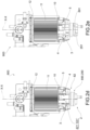
- reference numeral 900 indicates a filtration assembly in accordance with the present invention as a whole.
- the axis X-X shows the extension direction along which and about which said filtration assembly 1 and the related components extend.
- numeral 1 indicates a filtering cartridge and numeral 2 indicates an auxiliary device.
- the filtering cartridge 1 and the auxiliary device 2 in turn extend along and about the axis X-X.
- the filtering cartridge 1 and the auxiliary device 2 are specifically suitable to mutually engage and disengage.
- the filtration assembly 900 further comprises engagement/disengagement means 3 comprising cartridge members 4 comprised in the filtering cartridge 1 and device members 5 comprised in the auxiliary device 2.
- the cartridge members 4 and the device members 5 are specifically conformed to be configurable in an engagement configuration, by means of a reciprocal axial action along the axis X-X, and in a disengagement configuration, by means of a reciprocal action of rotation about the axis X-X, respectively.
- the engagement/disengagement means 3 are not mutually engageable by means of operations other than a movement in the axial direction. Furthermore, the engagement/disengagement means 3 are not mutually disengageable by means of operations other than a movement in the rotational direction.
- the engagement/disengagement operations are exclusively intended as those operations which involve the mutual engagement between the cartridge members 4 and device members 2 or which involve the mutual disengagement between the cartridge members 4 and device members 2.
- these operations require, upstream or downstream, further approaching or moving away operations (in the axial direction and/or in the rotary direction) required for the complete execution of the engagement/disengagement operations.
- the filtration assembly 1 also comprises objectification elements required to determine the mutual angular position of the respective cartridge members 4 and device members 5 and ensure the correct execution of the mutual engagement or disengagement steps in the axial direction.
- said objectification elements are housed on the various components involved in the aforementioned operations, for example the filtering cartridge 1 and/or the auxiliary device 2 and/or the optional filter body 8 described below.
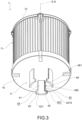
- the filtering cartridge 1 comprises an end plate 10, at least one filtering septum 11, preferably of the hollow cylindrical type, which is traversable by the fluid radially, and a secondary end plate 12.
- the cartridge members 4 are positioned, preferably comprised, in said end plate 10.
- the cartridge members 4 extend substantially parallel to and about the axis X-X.
- the cartridge members 4 comprise at least two blocking groups 40 angularly spaced apart, preferably equally spaced apart.
- the cartridge members 4 comprise three or four blocking groups 40 angularly spaced apart, preferably equally spaced apart.
- said blocking groups 40 lie on an imaginary plane that extends radially spaced apart from the axis X-X. In other words, the blocking groups 40 are substantially planar and arched.
- the blocking groups 40 are angularly equidistant from the axis X-X.
- the blocking groups 40 are all positioned at the same distance from the axis X-X.
- each blocking group 40 has a respective distance from the axis X-X.
- each blocking group 40 comprises a stem 41 and at least one tooth 42.
- the tooth 42 is positioned at the axial end of the stem 41 projecting therefrom in a lateral direction, that is, in a circumferential or tangential direction, defining an engagement undercut 43 with the stem 41.
- the stem 41 and tooth 42 give the blocking group 40, which lies on the respective imaginary plane, a substantially "L" shape.
- a blocking group 40 comprises two teeth 42 at the axial end of the stem 41.
- the stem 41 and teeth 42 give the blocking group 40, which lies on the respective imaginary plane, a substantially "T" shape.
- the device members 5 are positioned and shaped complementarily to the cartridge members 4.
- the device members 5 comprise at least one housing region 52 and a lug 53.
- the tooth 42 in the engagement configuration, is housed in a snap-fit manner in the respective housing region 52 specially shaped.
- the lug 53 in the engagement configuration, is housed in the undercut 43.
- the approach of the filtering cartridge 1 and the auxiliary device 2 in the axial direction results in the mutual engagement of the tooth 42 on the lug 53.
- This engagement results in the elastic flexing of the blocking group 40 in a radial direction and therefore in the axial snap-fit insertion of the cartridge members 4 into the device members 5.
- the housing region 52 also houses the stem 41 of the respective blocking group 40.
- the housing region 52 houses at least the respective tooth 42, but in some preferred embodiments, the housing region 52 houses the entire blocking group 40, that is, both the tooth 42 and the stem 41.
- the cartridge members 4 and the device members 5 comprise a cartridge edge 48 and a device edge 58.
- the cartridge edge 48 and the device edge 58 extend substantially along the axis X-X.
- the cartridge edge 48 is the outer, lateral edge of the blocking group 40.
- said cartridge edge 48 extends along the stem 41 and/or along the tooth 42.
- the device edge 58 laterally delimits the housing region 52 facing it.
- said device edge 58 extends laterally, defining the housing region 52, and/or extends along the lug 53.
- the device edge 58 is located on one of the two sides of the housing region 52.
- the cartridge edge 48 and the device edge 58 are suitable to mutually engage in the rotary disengagement action.
- cartridge edge 48 and device edge 58 is specifically shaped, thus identifying a ramp.
- the remaining edge is therefore suitable to slide (during the rotary disengagement operations) on said ramp.
- the remaining edge is thus suitable to slide (during the rotary disengagement operations) on said ramp, causing the elastic flexing of the blocking group 40 in a radial direction, freeing each tooth 42 from the related housing region 52.
- the shaped edge that identifies the ramp comprises a first edge, radially proximal to the axis X-X, and a second edge, radially distal from the axis X-X.
- the respective blocking group 40 elastically flexes in a radial direction so that the tooth 42 leaves the respective housing region 52.
- the shaped edge it is possible to extract the blocking group 40 fixed in a snap-fit manner to the device members 5.
- the cartridge members 4 and the device members 5 are mutually disengageable.
- the auxiliary device 2 is disassemblable from the filtering cartridge 1.
- the shaped edge that identifies the ramp comprises a first edge and a second edge having different radial distance from the axis X-X.
- first edge is radially spaced apart from the axis X-X by a first radial distance r1
- the second edge is radially spaced apart from the axis X-X by a second radial distance r2.
- the value of said second radial distance r2 is greater than the value of said first distance r1.
- both the cartridge edge 48 and the device edge 58 are complementarily shaped, each identifying a ramp comprising a first edge, radially proximal to the axis X-X, and a second edge, radially distal from the axis X-X.
- At least one of the cartridge edge 48 and the device edge 58 is shaped thus identifying the ramp, while the other one has a substantially arched or in square shape to allow it to slide on the ramp.
- the cartridge edge 48 comprises a first cartridge edge 481 and a second cartridge edge 482.
- the device edge 58 comprises a first device edge 581 and a second device edge 582.
- the cartridge edge 48 is positioned on the stem 41.
- the cartridge edge 48 is positioned on the tooth 42.
- the cartridge edge 48 is positioned on both the stem 41 and the tooth 42.
- the device edge 58 is positioned on the lug 53.
- the device edge 58 is positioned on the sidewall delimiting the housing region 52. In a variant, the device edge 58 is positioned on both the lug 53 and the sidewall delimiting the housing region 52.
- each edge is positioned to extend linearly on the respective component. According to some embodiments, the edge extends over a single component having a substantially rectilinear course. According to other embodiments, the edge extends over a plurality of components having a segmented course.
- each edge may fully extend only on the blocking group or on the housing region or, alternatively, extend on both the blocking group and the housing region 52, but in different axial portions along the axis X-X.
- each tooth 42 comprises a tilted cartridge edge 421 so as to have a tapered shape in the lateral direction.
- said tilted cartridge edge 421 faces the undercut 43.
- each lug 53 comprises a tilted protruding edge 531 specifically shaped similarly to the tilted cartridge edge 421.
- said tilted protruding edge 531 faces the housing region 52.
- the tilted cartridge edge 421 and the tilted protruding edge 531 comprise a cartridge engagement wall 4210 and a lug engagement wall 5310, respectively, which are preferably adjacent on an imaginary plane parallel to or at most inclined with respect to an imaginary plane orthogonal to the axis X-X, so as to prevent the tooth 42 from slipping on the lug 53 in an axial pulling action.
- the cartridge engagement wall 4210 and the lug engagement wall 5310 are such as to discharge any axial pulling actions onto each other.
- the cartridge engagement wall 4210 and the lug engagement wall 5310 are orthogonal to the axis X-X.
- the cartridge engagement wall 4210 and the lug engagement wall 5310 are inclined with respect to the axis X-X, thus identifying a cartridge retention undercut 421' and a lug retention undercut 531' suitable to house a portion of the lug 53 and of the tooth 52, respectively.
- the tooth 42 and the lug 53 are shaped to interpenetrate each other, creating a snap-fit coupling between the cartridge and the non-removable auxiliary device through an axial pulling action in the opposite direction to that with which the engagement is obtained.
- only the described mutual engagement between the cartridge edges and the device edges allow the release of the coupling and the decoupling between said components.
- the filtration assembly 900 further comprises a filter body 8 comprising a filtration chamber 80.
- the filtering cartridge 1 is housable in said filtration chamber 80 to perform said filtration operations.
- the auxiliary device 2 is for example a sensor group, and/or a cap group, being engageable with the filtering cartridge 1 to perform the specific operations for which it is intended.
- the auxiliary device 2 is a sensor group suitable to detect the presence of water (for example water separated from the fuel in diesel-type fuel filtration operations) collected inside the filtration assembly 1.
- the auxiliary device 2 is a cap group suitable to allow the drainage of the filtration assembly 1; preferably, it is a cap group suitable to allow the drainage of the water (for example the water separated from the fuel in diesel-type fuel filtration operations) collected inside the filtration assembly 1.
- the auxiliary device 2 is a heater group.
- the auxiliary device 2 is a pressure and/or temperature detection group.
- the auxiliary device 2 is a control unit comprising specific control valve means, for example, a bleed valve, a bypass valve, or a thermostatic valve.
- the auxiliary device 2 comprises a plurality of the aforementioned types of features, for example being both a cap group and a sensor group and/or a heater group, and/or a detection and/or control group.
- the auxiliary device 2 is also engageable with the filter body 8.
- the filter body 8 comprises a through opening 89 in which the auxiliary device 2 is housed.
- said through opening 89 is positioned along the axis X-X.
- said through opening 89 is concentric to the axis X-X.
- the auxiliary device 2 sealingly engages the filter body 8.
- the filtration chamber 20 is delimited in the mutual engagement between the auxiliary device 2 and the filter body 8.
- the auxiliary device 2 sealingly engages the filter body 8.
- the through opening 89 is delimited by an opening ring 890 and the auxiliary device 2 is positionable in the through opening 89 comprising an auxiliary collar 29 suitable to engage the opening ring 890.
- the auxiliary device comprises a preferably radial, annular gasket 299 suitable to engage the opening ring 890.
- the opening ring 890 and the auxiliary collar 29 have an annular extension.
- the opening ring 890 and the auxiliary collar 29 comprise, over the length of said annular extension, engagement steps 891, 291 inclined with respect to a plane orthogonal to the axis X-X, respectively.
- the disengagement between said steps imposes the rotation direction of the disengagement.
- said steps are specially shaped to slide over one another and allow a rotational disengagement between the auxiliary device 2 and the filter body 8.
- said disengagement between the auxiliary device 2 and the filter body 8 also simultaneously results in the release (disengagement) between the cartridge members 4 and the device members 5.
- said steps extend circumferentially for a section that is sufficient for the disengagement on the ramp between the cartridge members 4 and device members 5.
- the filter body 8 consists of two half-shells 81, 82 mutually screwable together.
- the auxiliary device 2 is operatively connected, according to the above-described modes, to one of the two half-shells.
- the through opening 89 is obtained in a half-shell 82.
- the mutual unscrewing of the two half-shells is such as to results in the mutual disengagement between the cartridge members 4 and the device members 5.
- the housing region 52 is formed on the auxiliary device 2 facing radially outwards, i.e., radially facing away from the axis X-X, i.e., in which the cartridge members 4 are outside the device members 5.
- the cartridge members 4 surround the device members 5.
- the housing region 52 is formed on the auxiliary device 2 facing radially inwards, i.e., facing the axis X-X, i.e., in which the cartridge members 4 are inside the device members 5.
- the cartridge members 4 are surrounded by the device members 5.
- the engagement operations between the filtering cartridge and the auxiliary device involve a single step of mutual axial insertion.
- the disengagement operations between the filtering cartridge and the auxiliary device involve a single step of mutual rotation.
- the operations are substantially guided and therefore errorproof.
- the engagement and disengagement operations of the filtering cartridgefilter body are highly simplified, intuitive, and guided.
- the engagement/disengagement means ensure the fixed and safe axial positioning of the two components, as well as maintained over time.
- the axial blocking action achieved by the lateral portions of the respective teeth is performed in an effective and reliable manner.
- the axial blocking action due to the tilted edges is discharged onto the complementary components provided on the filter body, in an effective manner.
- the geometry of the coupling system is simplified, thus simplifying the dimensioning of the teeth and the respective seats, and advantageously minimizing the complexity of the molds used for the production of the engagement/disengagement means and the related costs.
- a further advantage of the present invention is that the installation of filtering cartridges not provided with blocking groups such as those described on filter bodies is not allowed.
- the engagement/disengagement means have a small axial footprint, allowing a maximization of the filtering surface of the filtering septum, thus meeting the needs of the specific filtration group.
- the described engagement/disengagement means are easily implementable on filtering cartridges of different sizes and diameters.
- the described engagement/disengagement means are easily implementable on end plates of different shapes, allowing the implementation of the coupling system on both cylindrical cartridges and cartridges having a main extension direction, for example with rectangular or elliptical end plates, and on irregularly shaped cartridges.
- the engagement means have a small radial footprint and are providable on both filtering cartridges affected by radial flow and filtering cartridges affected by axial flow.
- the auxiliary device directly engages the filtering cartridge.
- the engagement between the filtering cartridge and the auxiliary device allows the elimination of any additional fixing systems provided on the auxiliary device, thus simplifying the shape and reducing the production cost thereof.
- the engagement between the filtering cartridge and the auxiliary device can be used for filtering devices in which the axis is vertically oriented, horizontally oriented or inclined with respect to the ground, under use conditions thereof.
- the auxiliary device is housable and suitable to form part of the filter body.
- the mutual engagement between the auxiliary device and the filter body makes the engagement between the auxiliary device and the filtering cartridge more solid.
- the mutual engagement between the auxiliary device and the filter body makes the auxiliary device an integral part, as well as an "active" component of the filter body, for example by operating as a sensor or as a drain plug for the filtration chamber.
Landscapes
- Chemical & Material Sciences (AREA)
- Chemical Kinetics & Catalysis (AREA)
- Physics & Mathematics (AREA)
- Geometry (AREA)
- Lubrication Details And Ventilation Of Internal Combustion Engines (AREA)
- Filtration Of Liquid (AREA)
- Separation Using Semi-Permeable Membranes (AREA)
- Water Treatment By Sorption (AREA)
Claims (15)
- Filtrationsanordnung (900) eines Fluids bzw. einer Flüssigkeit eines Fahrzeugs, die sich entlang einer Achse (X-X) erstreckt und umfasst:i) eine Filterpatrone (1);ii) ein Hilfsvorrichtung (2);ii) Eingriffs-/Lösemittel (3), umfassend Patronenglieder (4), die in der Filterpatrone (1) enthalten sind, und Vorrichtungsglieder (5), die in der Hilfsvorrichtung (2) enthalten sind, die jeweils speziell geformt sind, um in einer Eingriffskonfiguration mittels einer reziproken axialen Aktion entlang der Achse (X-X) und in einer Lösekonfiguration mittels einer reziproken Rotationsaktion um die Achse (X-X) konfigurierbar zu sein;wobei die Filterpatrone (1) an einem axialen Ende eine Endplatte (10) umfasst, auf der die Patronenglieder (4) positioniert sind, die sich im Wesentlichen parallel und um die Achse (X-X) erstrecken;wobei die Patronenglieder (4) zumindest zwei Blockiergruppen (40) umfassen, die jeweils einen Schaft (41) und zumindest einen Zahn (42) umfassen, der an dem axialen Ende des Schafts (41) positioniert ist, wobei er davon in seitlicher Richtung vorsteht, das heißt, in einer Umfangs- oder Tangentialrichtung, wobei er mit dem Schaft (41) eine Eingriffshinterschneidung (43) definiert;wobei die Vorrichtungsglieder (5) zumindest einen Gehäusebereich (52) und einen Ansatz (53) umfassen;wobei in der Eingriffskonfiguration der Zahn (42) in Schnapppassung in dem jeweils speziell geformten Gehäusebereich (52) untergebracht ist und der Ansatz (53) in der Hinterschneidung (43) untergebracht ist;wobei die Patronenglieder (4) und die Vorrichtungsglieder (5) einen Patronenrand (48) und einen Vorrichtungsrand (58) umfassen, der sich im Wesentlichen entlang der Achse (X-X) erstreckt, geeignet, bei der Rotationslöseaktion miteinander in Eingriff zu kommen, wobei zumindest einer des Patronenrands (48) und des Vorrichtungsrands (58) so geformt ist, dass er eine Rampe identifiziert, die einen ersten Rand radial proximal zu der Achse (X-X) und einen zweiten Rand radial distal von der Achse (X-X) umfasst;wobei die Filtrationsanordnung (900) dadurch gekennzeichnet ist, dass sich beim gegenseitigen Eingriff zwischen dem Patronenrand (48) und dem Vorrichtungsrand (58) die jeweilige Blockiergruppe (40) in einer radialen Richtung derart elastisch biegt, dass der Zahn (42) den jeweiligen Gehäusebereich (52) verlässt.
- Filtrationsanordnung (900) nach Anspruch 1, wobei sowohl der Patronenrand (48) als auch der Vorrichtungsrand (58) komplementär geformt sind, wobei sie jeweils eine Rampe identifizieren, die einen ersten Rand radial proximal zu der Achse (X-X) und einen zweiten Rand radial distal von der Achse (X-X) umfasst.
- Filtrationsanordnung (900) nach einem der vorhergehenden Ansprüche, wobei der Patronenrand (48) an dem Schaft (41) und/oder an dem Zahn (42) positioniert ist, während der Vorrichtungsrand (58) an dem Ansatz (53) und/oder an einer Seitenwand positioniert ist, die den Gehäusebereich (52) begrenzt.
- Filtrationsanordnung (900) nach einem der vorhergehenden Ansprüche, wobei jeder Zahn (42) eine geneigte Patronenkante (421) derart aufweist, dass er eine verjüngte Form in einer lateralen Richtung aufweist, wobei die geneigte Patronenkante (421) der Hinterschneidung (43) zugewandt ist, wobei jeder Ansatz (53) einen speziell geformten geneigten vorstehenden Rand (531) umfasst.
- Filtrationsanordnung (900) nach Anspruch 4, wobei der geneigte Patronenrand (421) und der geneigte vorstehende Rand (531) jeweils eine Patroneneingriffswand (4210) und eine Naseneingriffswand (5310) umfassen, die vorzugsweise auf einer imaginären Ebene parallel oder höchstens geneigt bezüglich einer imaginären Ebene orthogonal zu der Achse (X-X) derart liegen, dass sie verhindern, dass der Zahn (42) bei einer axialen Zugaktion auf dem Ansatz (53) verrutscht.
- Filtrationsanordnung (900) nach einem der vorhergehenden Ansprüche, wobei die Patronenglieder (4) und folglich die Vorrichtungseingriffsglieder (5) auf einer imaginären Ebene liegen, die sich radial beabstandet bezüglich der Achse (X-X) erstreckt.
- Filtrationsanordnung (900) nach einem der vorhergehenden Ansprüche, wobei die Patronenglieder (4) zwei, drei oder vier Blockiergruppen (40) im gleichen Winkelabstand umfassen.
- Filtrationsanordnung (900) nach einem der vorhergehenden Ansprüche, wobei jede Blockiergruppe (40) an dem Schaft (41) zwei Zähne (42) umfasst, die sich von dem Schaft (41) in zwei entgegengesetzte laterale Richtungen erstrecken, wobei die Vorrichtungsglieder (5) speziell geformt sind, um beide Zähne (42) aufzunehmen.
- Filtrationsanordnung (900) nach einem der vorhergehenden Ansprüche, ferner umfassend einen Filterkörper (8), der eine Filtrationskammer (80) umfasst, wobei die Filterpatrone (1) in der Filterkammer (80) aufnehmbar ist.
- Filtrationsanordnung (900) nach einem der vorhergehenden Ansprüche, wobei die Hilfsvorrichtung (2) beispielsweise eine Kappengruppe und/oder eine Sensorgruppe und/oder eine Heizergruppe und/oder eine Erfassungs- und/oder Steuer- bzw. Regelgruppe ist, die mit der Filterpatrone (1) in Eingriff bringbar ist, um die spezifischen Operationen auszuführen, für die sie bestimmt ist.
- Filtrationsanordnung (900) nach den Ansprüchen 9 und 10, wobei die Hilfsvorrichtung (2) auch mit dem Filterkörper (8) in Eingriff bringbar ist.
- Filtrationsanordnung (900) nach Anspruch 11, wobei der Filterkörper (8) entlang der Achse (X-X) eine Durchgangsöffnung (89) umfasst, die durch einen Öffnungsring (890) begrenzt ist, und die Hilfsvorrichtung (2) in der Durchgangsöffnung (89) positionierbar ist, umfassend einen Hilfskragen (29), der zum Eingriff mit dem Öffnungsring (890) geeignet ist, wobei die Hilfsvorrichtung (2) dichtend in den Filterkörper (8) eingreift.
- Filtrationsanordnung (900) nach Anspruch 12, wobei der Öffnungsring (890) und der Hilfskragen (29) Eingriffsstufen (891, 291) umfassen, die jeweils bezüglich der Achse (X-X) geneigt sind, wobei das Lösen zwischen diesen Stufen die Rotationsrichtung des Lösens auferlegt bzw. festlegt.
- Filtrationsanordnung (900) nach einem der Ansprüche 10 bis 13, wobei der Gehäusebereich (52) an der Hilfsvorrichtung (2) radial nach außen gewandt, d. h. radial von der Achse (X-X) abgewandt ausgebildet ist, d. h. wobei sich die Patronenglieder (4) außerhalb der Vorrichtungsglieder (5) befinden, oder umgekehrt der Gehäusebereich (52) an der Hilfsvorrichtung (2) radial nach innen gewandt, d. h. der Achse (X-X) zugewandt ausgebildet ist, d. h. wobei sich die Patronenglieder (4) innerhalb der Patronenglieder (5) befinden.
- Filtrationsanordnung (900) nach einem der vorhergehenden Ansprüche, wobei die Filterpatrone (1) umfasst:- die Endplatte (10);- zumindest ein Filterseptum (11), vorzugsweise von hohlzylindrischen Typ, das von der Flüssigkeit radial durchströmt werden kann;- eine sekundäre Endplatte (12);wobei sich die Endplatte (10) und die sekundäre Endplatte (12) an den axialen Enden des Filterseptums (11) befinden.
Applications Claiming Priority (2)
| Application Number | Priority Date | Filing Date | Title |
|---|---|---|---|
| IT102019000014280A IT201900014280A1 (it) | 2019-08-07 | 2019-08-07 | Assieme di filtrazione comprendente una cartuccia filtrante e un dispositivo ausiliario |
| PCT/IB2020/057113 WO2021024091A1 (en) | 2019-08-07 | 2020-07-28 | Filtration assembly comprising a filtering cartridge and an auxiliary device |
Publications (3)
| Publication Number | Publication Date |
|---|---|
| EP4010102A1 EP4010102A1 (de) | 2022-06-15 |
| EP4010102B1 true EP4010102B1 (de) | 2023-08-09 |
| EP4010102C0 EP4010102C0 (de) | 2023-08-09 |
Family
ID=69375671
Family Applications (1)
| Application Number | Title | Priority Date | Filing Date |
|---|---|---|---|
| EP20757405.4A Active EP4010102B1 (de) | 2019-08-07 | 2020-07-28 | Filtrationsanordung mit filterkartusche und hilfsvorrichtung |
Country Status (5)
| Country | Link |
|---|---|
| US (1) | US20220280891A1 (de) |
| EP (1) | EP4010102B1 (de) |
| CN (1) | CN114945420B (de) |
| IT (1) | IT201900014280A1 (de) |
| WO (1) | WO2021024091A1 (de) |
Families Citing this family (5)
| Publication number | Priority date | Publication date | Assignee | Title |
|---|---|---|---|---|
| WO2018175289A1 (en) | 2017-03-20 | 2018-09-27 | Cummins Filtration Ip, Inc. | Filter assembly with an inner filter element with a top rib |
| CN116099477A (zh) | 2017-07-13 | 2023-05-12 | 康明斯滤清系统知识产权公司 | 带有导向特征的端板 |
| CN115178005B (zh) * | 2022-09-13 | 2023-01-24 | 烟台枫林新材料有限公司 | 一种聚酯树脂循环过滤生产装置 |
| WO2025133820A1 (en) * | 2023-12-20 | 2025-06-26 | Ufi Filters S.P.A. | Filtration assembly |
| CN119139793B (zh) * | 2024-11-18 | 2025-03-04 | 杭州富阳鸿源再生资源利用有限公司 | 一种高纯氢氧化铜自动化过滤脱水设备 |
Family Cites Families (24)
| Publication number | Priority date | Publication date | Assignee | Title |
|---|---|---|---|---|
| US4291651A (en) * | 1978-10-06 | 1981-09-29 | Villella Tony R | Internal combustion engine |
| US5045192A (en) * | 1986-06-03 | 1991-09-03 | Facet Enterprises, Inc. | Filter assembly with lockable lug means |
| US5484527A (en) * | 1993-12-13 | 1996-01-16 | Stanadyne Automotive Corp. | Module for filter assembly base |
| US6364121B1 (en) * | 1999-07-19 | 2002-04-02 | Stanadyne Corporation | Filter cartridge with grommet spring |
| KR100975997B1 (ko) * | 2000-08-11 | 2010-08-17 | 로저 피. 리이드 | 필터 홀더에 필터 카트리지를 연결시키는 키 시스템 |
| ITRE20010065A1 (it) * | 2001-06-12 | 2002-12-12 | Ufi Universal Filter Int Spa | Filtro per liquidi per motori a combustione dei veicoli |
| US7473048B2 (en) * | 2002-04-18 | 2009-01-06 | Sakura Rubber Co., Ltd. | Coupling apparatus for structural members |
| US6911143B2 (en) * | 2002-10-31 | 2005-06-28 | Stanadyne Corporation | Base receptacle for filter cartridge incorporating a peripheral compatibility matrix |
| JP4649401B2 (ja) * | 2003-04-10 | 2011-03-09 | ポール・コーポレーション | フィルタアッセンブリー及びフィルタカートリッジをフィルタアッセンブリーから除去する方法 |
| EP1850941B1 (de) * | 2005-02-22 | 2011-04-13 | Baldwin Filters, Inc. | Filtervorrichtung |
| WO2008030707A1 (en) * | 2006-09-05 | 2008-03-13 | Pall Corporation | Filter elements and assemblies |
| US20140163664A1 (en) * | 2006-11-21 | 2014-06-12 | David S. Goldsmith | Integrated system for the ballistic and nonballistic infixion and retrieval of implants with or without drug targeting |
| GB0715247D0 (en) * | 2007-08-04 | 2007-09-12 | Parker Hannifin Ltd | Filter assembly |
| WO2009132291A2 (en) * | 2008-04-25 | 2009-10-29 | Donaldson Company, Inc. | Top load liquid filter assembly, system, and methods |
| US8105483B2 (en) * | 2008-10-15 | 2012-01-31 | Cummins Filtration Ip, Inc. | Snap-in water sensor |
| BRPI0924850B1 (pt) * | 2009-04-20 | 2019-04-30 | Parker Hannifin Manufacturing Netherlands (Filtration) B.V. | Conjunto de filtro, elemento de filtro, e, métodos para remover um elemento de filtro de um conjunto de filtro, e para substituir o elemento de filtro |
| IT1398974B1 (it) * | 2010-03-24 | 2013-03-28 | Ufi Filters Spa | Filtro per motori a combustione interna. |
| DE102010027150B4 (de) * | 2010-07-14 | 2016-08-11 | Mann + Hummel Gmbh | Filterelement und Filtermodul |
| WO2015106315A1 (en) * | 2014-01-20 | 2015-07-23 | Km Electronic Developments Pty Ltd | A fluid distribution system for selectively distributing fluid from multiple locations and conduit arrangement for distributing fluid from multiple locations |
| CN104368186A (zh) * | 2014-11-11 | 2015-02-25 | 重庆颐洋企业发展有限公司 | 一种滤芯筒体锁紧件 |
| US11596880B2 (en) * | 2017-07-12 | 2023-03-07 | Ufi Filters S.P.A. | Filter cartridge |
| IT201800001611A1 (it) * | 2018-01-22 | 2019-07-22 | Ufi Filters Spa | Gruppo filtrante |
| IT201800001629A1 (it) * | 2018-01-22 | 2019-07-22 | Ufi Filters Spa | Gruppo filtrante |
| CN209155237U (zh) * | 2018-08-28 | 2019-07-26 | 上海欧菲滤清器有限公司 | 流体过滤器组及其过滤器滤芯和基部组件 |
-
2019
- 2019-08-07 IT IT102019000014280A patent/IT201900014280A1/it unknown
-
2020
- 2020-07-28 EP EP20757405.4A patent/EP4010102B1/de active Active
- 2020-07-28 WO PCT/IB2020/057113 patent/WO2021024091A1/en not_active Ceased
- 2020-07-28 US US17/632,699 patent/US20220280891A1/en active Pending
- 2020-07-28 CN CN202080064254.3A patent/CN114945420B/zh active Active
Also Published As
| Publication number | Publication date |
|---|---|
| CN114945420A (zh) | 2022-08-26 |
| CN114945420B (zh) | 2024-07-02 |
| US20220280891A1 (en) | 2022-09-08 |
| IT201900014280A1 (it) | 2021-02-07 |
| WO2021024091A1 (en) | 2021-02-11 |
| EP4010102A1 (de) | 2022-06-15 |
| EP4010102C0 (de) | 2023-08-09 |
Similar Documents
| Publication | Publication Date | Title |
|---|---|---|
| EP4010102B1 (de) | Filtrationsanordung mit filterkartusche und hilfsvorrichtung | |
| RU2706054C2 (ru) | Канистровая система фильтрации со стоком, взаимодействующим с фильтрующим элементом | |
| EP3096857B1 (de) | Filterelement mit endkappendichtung und filteranordnung | |
| EP2699329B1 (de) | Filtergruppe | |
| US9446333B2 (en) | Keyed thread engagement on spin-on filter element | |
| KR102240601B1 (ko) | 스핀-온 필터 요소 상의 키형 쓰레드 결합 | |
| WO2015050580A1 (en) | Fuel filter cartridge and method of construction thereof | |
| US20150090653A1 (en) | Fuel Filter Cartridge and Method of Construction Thereof | |
| WO2010065180A1 (en) | Filter element with threaded top endplate | |
| US12318721B2 (en) | Self-assisting element removal features for a filtration system | |
| US12324996B2 (en) | Filtration assembly including a filtering cartridge and a filter body | |
| US8409317B2 (en) | Filter assembly with housing structure | |
| WO2015112421A1 (en) | Filter base system and filter assembly | |
| US11845026B2 (en) | Filter cartridge with engagement members | |
| CN112154023B (zh) | 包括可移除式出口导管的过滤器组件 | |
| US10035087B2 (en) | Keyed thread engagement for filter element | |
| EP1052490A2 (de) | Schnappbefestigungsvorrichtung | |
| MXPA05012198A (es) | Ensamble para filtro de fluido con cubierta muescada. | |
| CN121443368A (zh) | 用于过滤系统的排放关闭元件、过滤元件及过滤系统 | |
| HK1187566B (en) | Canister filter system with drain that cooperates with filter element |
Legal Events
| Date | Code | Title | Description |
|---|---|---|---|
| STAA | Information on the status of an ep patent application or granted ep patent |
Free format text: STATUS: UNKNOWN |
|
| STAA | Information on the status of an ep patent application or granted ep patent |
Free format text: STATUS: THE INTERNATIONAL PUBLICATION HAS BEEN MADE |
|
| PUAI | Public reference made under article 153(3) epc to a published international application that has entered the european phase |
Free format text: ORIGINAL CODE: 0009012 |
|
| STAA | Information on the status of an ep patent application or granted ep patent |
Free format text: STATUS: REQUEST FOR EXAMINATION WAS MADE |
|
| 17P | Request for examination filed |
Effective date: 20220131 |
|
| AK | Designated contracting states |
Kind code of ref document: A1 Designated state(s): AL AT BE BG CH CY CZ DE DK EE ES FI FR GB GR HR HU IE IS IT LI LT LU LV MC MK MT NL NO PL PT RO RS SE SI SK SM TR |
|
| DAV | Request for validation of the european patent (deleted) | ||
| DAX | Request for extension of the european patent (deleted) | ||
| GRAP | Despatch of communication of intention to grant a patent |
Free format text: ORIGINAL CODE: EPIDOSNIGR1 |
|
| STAA | Information on the status of an ep patent application or granted ep patent |
Free format text: STATUS: GRANT OF PATENT IS INTENDED |
|
| INTG | Intention to grant announced |
Effective date: 20230228 |
|
| GRAS | Grant fee paid |
Free format text: ORIGINAL CODE: EPIDOSNIGR3 |
|
| GRAA | (expected) grant |
Free format text: ORIGINAL CODE: 0009210 |
|
| STAA | Information on the status of an ep patent application or granted ep patent |
Free format text: STATUS: THE PATENT HAS BEEN GRANTED |
|
| AK | Designated contracting states |
Kind code of ref document: B1 Designated state(s): AL AT BE BG CH CY CZ DE DK EE ES FI FR GB GR HR HU IE IS IT LI LT LU LV MC MK MT NL NO PL PT RO RS SE SI SK SM TR |
|
| REG | Reference to a national code |
Ref country code: GB Ref legal event code: FG4D |
|
| REG | Reference to a national code |
Ref country code: CH Ref legal event code: EP |
|
| REG | Reference to a national code |
Ref country code: IE Ref legal event code: FG4D |
|
| REG | Reference to a national code |
Ref country code: DE Ref legal event code: R096 Ref document number: 602020015528 Country of ref document: DE |
|
| U01 | Request for unitary effect filed |
Effective date: 20230907 |
|
| U07 | Unitary effect registered |
Designated state(s): AT BE BG DE DK EE FI FR IT LT LU LV MT NL PT SE SI Effective date: 20230914 |
|
| PG25 | Lapsed in a contracting state [announced via postgrant information from national office to epo] |
Ref country code: GR Free format text: LAPSE BECAUSE OF FAILURE TO SUBMIT A TRANSLATION OF THE DESCRIPTION OR TO PAY THE FEE WITHIN THE PRESCRIBED TIME-LIMIT Effective date: 20231110 |
|
| PG25 | Lapsed in a contracting state [announced via postgrant information from national office to epo] |
Ref country code: IS Free format text: LAPSE BECAUSE OF FAILURE TO SUBMIT A TRANSLATION OF THE DESCRIPTION OR TO PAY THE FEE WITHIN THE PRESCRIBED TIME-LIMIT Effective date: 20231209 |
|
| PG25 | Lapsed in a contracting state [announced via postgrant information from national office to epo] |
Ref country code: RS Free format text: LAPSE BECAUSE OF FAILURE TO SUBMIT A TRANSLATION OF THE DESCRIPTION OR TO PAY THE FEE WITHIN THE PRESCRIBED TIME-LIMIT Effective date: 20230809 Ref country code: NO Free format text: LAPSE BECAUSE OF FAILURE TO SUBMIT A TRANSLATION OF THE DESCRIPTION OR TO PAY THE FEE WITHIN THE PRESCRIBED TIME-LIMIT Effective date: 20231109 Ref country code: IS Free format text: LAPSE BECAUSE OF FAILURE TO SUBMIT A TRANSLATION OF THE DESCRIPTION OR TO PAY THE FEE WITHIN THE PRESCRIBED TIME-LIMIT Effective date: 20231209 Ref country code: HR Free format text: LAPSE BECAUSE OF FAILURE TO SUBMIT A TRANSLATION OF THE DESCRIPTION OR TO PAY THE FEE WITHIN THE PRESCRIBED TIME-LIMIT Effective date: 20230809 Ref country code: GR Free format text: LAPSE BECAUSE OF FAILURE TO SUBMIT A TRANSLATION OF THE DESCRIPTION OR TO PAY THE FEE WITHIN THE PRESCRIBED TIME-LIMIT Effective date: 20231110 |
|
| PG25 | Lapsed in a contracting state [announced via postgrant information from national office to epo] |
Ref country code: PL Free format text: LAPSE BECAUSE OF FAILURE TO SUBMIT A TRANSLATION OF THE DESCRIPTION OR TO PAY THE FEE WITHIN THE PRESCRIBED TIME-LIMIT Effective date: 20230809 |
|
| PG25 | Lapsed in a contracting state [announced via postgrant information from national office to epo] |
Ref country code: ES Free format text: LAPSE BECAUSE OF FAILURE TO SUBMIT A TRANSLATION OF THE DESCRIPTION OR TO PAY THE FEE WITHIN THE PRESCRIBED TIME-LIMIT Effective date: 20230809 |
|
| PG25 | Lapsed in a contracting state [announced via postgrant information from national office to epo] |
Ref country code: SM Free format text: LAPSE BECAUSE OF FAILURE TO SUBMIT A TRANSLATION OF THE DESCRIPTION OR TO PAY THE FEE WITHIN THE PRESCRIBED TIME-LIMIT Effective date: 20230809 Ref country code: RO Free format text: LAPSE BECAUSE OF FAILURE TO SUBMIT A TRANSLATION OF THE DESCRIPTION OR TO PAY THE FEE WITHIN THE PRESCRIBED TIME-LIMIT Effective date: 20230809 Ref country code: ES Free format text: LAPSE BECAUSE OF FAILURE TO SUBMIT A TRANSLATION OF THE DESCRIPTION OR TO PAY THE FEE WITHIN THE PRESCRIBED TIME-LIMIT Effective date: 20230809 Ref country code: CZ Free format text: LAPSE BECAUSE OF FAILURE TO SUBMIT A TRANSLATION OF THE DESCRIPTION OR TO PAY THE FEE WITHIN THE PRESCRIBED TIME-LIMIT Effective date: 20230809 Ref country code: SK Free format text: LAPSE BECAUSE OF FAILURE TO SUBMIT A TRANSLATION OF THE DESCRIPTION OR TO PAY THE FEE WITHIN THE PRESCRIBED TIME-LIMIT Effective date: 20230809 |
|
| REG | Reference to a national code |
Ref country code: DE Ref legal event code: R097 Ref document number: 602020015528 Country of ref document: DE |
|
| PLBE | No opposition filed within time limit |
Free format text: ORIGINAL CODE: 0009261 |
|
| STAA | Information on the status of an ep patent application or granted ep patent |
Free format text: STATUS: NO OPPOSITION FILED WITHIN TIME LIMIT |
|
| 26N | No opposition filed |
Effective date: 20240513 |
|
| U20 | Renewal fee for the european patent with unitary effect paid |
Year of fee payment: 5 Effective date: 20240722 |
|
| PG25 | Lapsed in a contracting state [announced via postgrant information from national office to epo] |
Ref country code: MC Free format text: LAPSE BECAUSE OF FAILURE TO SUBMIT A TRANSLATION OF THE DESCRIPTION OR TO PAY THE FEE WITHIN THE PRESCRIBED TIME-LIMIT Effective date: 20230809 |
|
| REG | Reference to a national code |
Ref country code: CH Ref legal event code: PL |
|
| GBPC | Gb: european patent ceased through non-payment of renewal fee |
Effective date: 20240728 |
|
| PG25 | Lapsed in a contracting state [announced via postgrant information from national office to epo] |
Ref country code: CH Free format text: LAPSE BECAUSE OF NON-PAYMENT OF DUE FEES Effective date: 20240731 |
|
| PG25 | Lapsed in a contracting state [announced via postgrant information from national office to epo] |
Ref country code: GB Free format text: LAPSE BECAUSE OF NON-PAYMENT OF DUE FEES Effective date: 20240728 |
|
| U20 | Renewal fee for the european patent with unitary effect paid |
Year of fee payment: 6 Effective date: 20250523 |
|
| PG25 | Lapsed in a contracting state [announced via postgrant information from national office to epo] |
Ref country code: IE Free format text: LAPSE BECAUSE OF NON-PAYMENT OF DUE FEES Effective date: 20240728 |
|
| PG25 | Lapsed in a contracting state [announced via postgrant information from national office to epo] |
Ref country code: CY Free format text: LAPSE BECAUSE OF FAILURE TO SUBMIT A TRANSLATION OF THE DESCRIPTION OR TO PAY THE FEE WITHIN THE PRESCRIBED TIME-LIMIT; INVALID AB INITIO Effective date: 20200728 |
|
| PG25 | Lapsed in a contracting state [announced via postgrant information from national office to epo] |
Ref country code: HU Free format text: LAPSE BECAUSE OF FAILURE TO SUBMIT A TRANSLATION OF THE DESCRIPTION OR TO PAY THE FEE WITHIN THE PRESCRIBED TIME-LIMIT; INVALID AB INITIO Effective date: 20200728 |