EP4010124B1 - Centrifugeuse - Google Patents
Centrifugeuse Download PDFInfo
- Publication number
- EP4010124B1 EP4010124B1 EP20754704.3A EP20754704A EP4010124B1 EP 4010124 B1 EP4010124 B1 EP 4010124B1 EP 20754704 A EP20754704 A EP 20754704A EP 4010124 B1 EP4010124 B1 EP 4010124B1
- Authority
- EP
- European Patent Office
- Prior art keywords
- rotor
- centrifuge
- transceiver unit
- support
- transceiver
- Prior art date
- Legal status (The legal status is an assumption and is not a legal conclusion. Google has not performed a legal analysis and makes no representation as to the accuracy of the status listed.)
- Active
Links
Images



Classifications
-
- B—PERFORMING OPERATIONS; TRANSPORTING
- B04—CENTRIFUGAL APPARATUS OR MACHINES FOR CARRYING-OUT PHYSICAL OR CHEMICAL PROCESSES
- B04B—CENTRIFUGES
- B04B13/00—Control arrangements specially designed for centrifuges; Program control of centrifuges
-
- B—PERFORMING OPERATIONS; TRANSPORTING
- B04—CENTRIFUGAL APPARATUS OR MACHINES FOR CARRYING-OUT PHYSICAL OR CHEMICAL PROCESSES
- B04B—CENTRIFUGES
- B04B13/00—Control arrangements specially designed for centrifuges; Program control of centrifuges
- B04B13/003—Rotor identification systems
-
- B—PERFORMING OPERATIONS; TRANSPORTING
- B04—CENTRIFUGAL APPARATUS OR MACHINES FOR CARRYING-OUT PHYSICAL OR CHEMICAL PROCESSES
- B04B—CENTRIFUGES
- B04B9/00—Drives specially designed for centrifuges; Arrangement or disposition of transmission gearing; Suspending or balancing rotary bowls
- B04B9/02—Electric motor drives
-
- H—ELECTRICITY
- H04—ELECTRIC COMMUNICATION TECHNIQUE
- H04B—TRANSMISSION
- H04B5/00—Near-field transmission systems, e.g. inductive or capacitive transmission systems
- H04B5/40—Near-field transmission systems, e.g. inductive or capacitive transmission systems characterised by components specially adapted for near-field transmission
- H04B5/48—Transceivers
-
- B—PERFORMING OPERATIONS; TRANSPORTING
- B04—CENTRIFUGAL APPARATUS OR MACHINES FOR CARRYING-OUT PHYSICAL OR CHEMICAL PROCESSES
- B04B—CENTRIFUGES
- B04B9/00—Drives specially designed for centrifuges; Arrangement or disposition of transmission gearing; Suspending or balancing rotary bowls
- B04B9/14—Balancing rotary bowls ; Schrappers
- B04B9/146—Imbalance detection devices
-
- G—PHYSICS
- G08—SIGNALLING
- G08B—SIGNALLING SYSTEMS, e.g. PERSONAL CALLING SYSTEMS; ORDER TELEGRAPHS; ALARM SYSTEMS
- G08B7/00—Signalling systems according to two or more of groups G08B3/00 - G08B6/00
- G08B7/06—Signalling systems according to two or more of groups G08B3/00 - G08B6/00 using electric transmission, e.g. involving audible and visible signalling through the use of sound and light sources
Definitions
- the invention relates to a centrifuge according to the type specified in the preamble of claim 1.
- Centrifuging a biological or chemical sample to separate the sample components using a rotor of a centrifuge generally requires high angular speeds of the rotor.
- sample containers and rotors for different samples that can be operated with a basic model of a centrifuge.
- the rotor is interchangeably connected to a drive shaft of this centrifuge.
- a rotor type is selected based on the associated mechanical properties of that rotor.
- the availability of a variety of different types of rotors increases the centrifuge's versatility in, among other things, biological and chemical experimental research, but also in blood banks and medical laboratories.
- Each rotor type has a rotor identifier, which determines the type of rotor and its properties, for example a maximum safe rated speed, which generally depends on the maximum permissible stresses and forces caused by centrifugal forces. Operation above the maximum rated speed, which is set for safe operation of the rotor, can lead to rotor failure - associated with major damage. It is therefore extremely important that the control system of a centrifuge recognizes which rotor is in use and is being operated by the centrifuge and that the specified key figures, such as maximum speed and the like, are adhered to during operation of the centrifuge.
- Previously known rotor detection systems mainly rely on magnetic or optical sensors to record rotor detection.
- magnets are attached to the rotor in certain circular or ring-shaped arrangements. These magnets are assigned magnetic sensors on the housing, for example Hall sensors. Different numbers of magnets but also the distances between the magnets on the rotor are assigned to the rotor identification.
- the magnetic sensor is used to record the rotor identification.
- the control assigns the maximum permissible speed to the rotor.
- the rotor used is therefore always used at a specific, maximum permitted speed.
- Such a centrifuge is, for example, from EP 0 604 912 B1 known.
- the number of starts per rotor code is counted in the control and the user has the opportunity to monitor the number of running cycles, which works reliably as long as only one rotor always remains in the same centrifuge.
- the disadvantage is that the number of codes depends on the number of magnets and is therefore limited. This means that identical rotors are always equipped with the same code. If several identical rotors are used in one or more centrifuges, it is no longer possible to assign the number of cycles to a specific rotor.
- a centrifuge is known with a housing in which a rotor is arranged for receiving a sample to be centrifuged.
- the rotor sits releasably on a drive shaft, which is connected to a drive.
- the rotor is driven by the drive shaft and rotates around an axis of rotation.
- the rotor has a first, rotor-side transceiver unit with a transceiver antenna in the form of a transponder, which is excited via an electric field, whereby voltage is induced in the first transceiver unit.
- the transponder with transmitting/receiving antenna is arranged flat on the underside of the rotor.
- the first transceiver unit is assigned to a second transceiver unit on the housing side, which is connected to a voltage source.
- the transponder is a transceiver unit that works according to the query-response principle.
- a coded query signal received by the transponder is decrypted and evaluated after the questioner has been recognized and received other information.
- a coded response signal with the desired information, which is selectively intended for the requester, is then automatically sent out, which is also automatically decrypted and evaluated by the requester.
- All rotor-specific data is stored in the transponder. These are, for example: year of manufacture, serial number of production, maximum centrifuge action radius, maximum rotation frequency, parameters for the drive control, temperature compensation values, permissible unbalance values, i.e. permissible acceleration values, etc. It should also be possible to continuously store additional data in the transponder's memory , such as operating hours, running times, number of starts, etc.
- the ones from the DE 10 2004 002 110 A1 The known centrifuge has the disadvantage that it works very unsatisfactorily and is not suitable for series laboratory centrifuges. Reliable data transmission is not guaranteed because the transponder, i.e. the first transceiver unit, is installed horizontally on the rotor with a transceiver antenna on the underside and the second transceiver unit with a transceiver antenna is on the top of the drive motor is arranged lying flat horizontally. Both transmitter-receiver units are each arranged on an annular support concentric to the axis of rotation, but spaced apart with regard to the height of the axis of rotation.
- the function is disturbed by metals on the rotor and on the drive motor lying behind the first and second transceiver units.
- the rotor types have different dimensions, so that the distance between the transmitting and receiving antennas varies depending on the rotor type. Due to the different dimensions of the rotor types and a sum of tolerances in the axial direction, a defined distance between the first and second transmitter-receiver antenna is not possible.
- a generic centrifuge is from the JP 2015-20 123 A known, which discloses a centrifuge with a ring-shaped data storage device with an IC chip.
- the memory stores data for identifying and managing a rotor of the centrifuge.
- the memory of the IC chip is a non-volatile memory in which the stored data is not erased when the power is turned off.
- the IC chip is provided with a connection via wiring within the data storage device 42.
- the data used to identify and manage the rotor includes: B. the type, the production number, the number of uses, the cumulative usage time and the like. Of these, the number of usage times and cumulative usage time are rewritable data for life management.
- step 102 When the rotating shaft 7a (step 102, Fig. 10 ) rotates, for example, after the power is turned off due to a power failure or the like during operation, the power is turned on again in step 101 due to recovery, and it is assumed that the rotor 30 continues to rotate due to inertia. Therefore, in this case, the process waits until the rotation of the rotor 30 is stopped in step 102.
- the term “stop” can be used here e.g. B. include a sufficiently slow rotation speed of about 1 revolution per second or less and is not limited to a strictly stationary state.
- the arithmetic unit 14a is configured to control the actuator 70 to be in the unenergized state (OFF state) when the rotation of the rotating shaft 7a is detected.
- the computing unit 14a keeps the actuator 70 in the non-energized state (OFF state).
- the actuator 70 is operated.
- the actuator is turned on (step 103) to move the terminal 50 and the tip 50a to a terminal position where the terminal (electrode) 43 of the adapter 40 makes contact. Accordingly, as the rotating shaft 7a rotates, the terminal 50 is retracted to a position where the terminal (electrode) 43 of the adapter 40 makes contact. In the position where they do not come into contact with the terminal (electrode) 43 of the adapter 40, the terminal 50 and the lever 60 rotate the rotor 30. There is no interference.
- the arithmetic unit 14a determines whether data is sent to the data storage device 42 (IC chip 44) can be transmitted or received by it or not. This determines whether the rotor 30 is attached to the clutch unit 12 or not. Since the terminal (electrode) 43 has a continuous ring shape as described above, the user can connect the rotor 30 to the coupling part 12 in any position. The terminal 50 and the terminal (electrode) 43 are always in contact with each other so that power can be supplied and data can be sent and received. In addition, if the shape and size of the terminal 50 are appropriately selected, the terminal (electrode) 43 can have a short interrupted section, such as. B. have a C shape.
- step 104 When it is determined in step 104 that data can be sent/received to the data storage device 42 (IC chip 44) and the rotor 30 is connected to the coupling unit 12, the calculation unit 14a causes the operation of the rotor 30. That is, the Data storage device 42 (IC chip 44) reads the data including the identification information for identifying the rotor 30, such as the type and serial number, and the usage record including the number of usages and the cumulative usage time (step 107). The attached rotor 30 is specified based on the read identification information (step 108).
- a device for digital signal transmission for a rotating device which has two coils arranged coaxially to one another in close proximity to one another and centered on the axis of rotation of the device.
- One of the coils is permanently connected to a rotor and the other to a stator.
- One of the coils is supplied with a signal to be transmitted.
- the other coil serves as a receiver.
- the radial distance between the coils is within 25% of their diameter.
- the distance between the coils and the metal masses must be sufficient and is within 25% of the diameter of the coils, but is more than 1% of the diameter of the coils.
- the coils are embedded in plastic resin or insulating material to avoid magnetic losses.
- the coils serve as transformers to supply electrical energy from the machine to the rotor, without rotating electrical contact between the stator and the rotor.
- the invention is based on the object of developing a centrifuge according to the type specified in the preamble of claim 1 in such a way that a securely functioning transmission of data between the first and second transceiver units is made possible regardless of the rotor type. This should be ensured especially when using different rotors in a centrifuge. In particular, the size and design of the rotors should not be changed compared to the previous design.
- the invention is based on the knowledge that a concentric arrangement of the transmitting/receiving antennas that overlaps in the direction of the axis of rotation expands and improves the design options for optimizing data transmission.
- the carrier of one transceiver unit has a smaller diameter than the carrier of the other transceiver unit.
- the transmitting/receiving antennas overlap in areas in the direction parallel to the axis of rotation. This means that the transmitting/receiving antennas can always be arranged in the same way to one another in a simple manner, regardless of the design and dimensions of the different rotor types.
- the quality of data transmission is no longer dependent on the rotor type or rotor design on the side facing the drive motor, for example at what distance the underside is arranged from the top of the drive motor.
- the new arrangement also allows tolerances to be easily compensated for.
- the transmitting/receiving antennas preferably overlap at least 50%, preferably 70%, in particular 90%, preferably 95%, particularly preferably 100%. This further improves the quality of data transmission between the transceiver units and the transmission and reception power of the transceiver units can be reduced. Also have Manufacturing tolerances, especially in the axial direction, have little influence on the quality of data transmission.
- the first carrier for the first transceiver unit has magnets as an identifier for the rotor.
- the second carrier for the second transceiver unit is provided with at least one Hall sensor for determining the rotor identification of the first carrier determined by the magnets. This makes redundant transmission of data, for example rotor identification, possible.
- the transmitter-receiver units have temperature-sensitive semiconductors with safety-critical functions, which can be heavily stressed and damaged or at least impaired in function, particularly if the permissible temperature when autoclaving the rotor is exceeded. In addition, these parts are also exposed to high centrifugal accelerations. Malfunctions that occur in the known transmitter-receiver units therefore lead to overstressing of the rotor with the resulting consequences. For this reason, the speed is additionally monitored using the proven so-called tacho coding made of magnets.
- the carrier is strip-shaped and is inserted into the groove of a carrier part and fixed in a casting compound.
- the ring-shaped carrier can each comprise a flexible, strip-shaped circuit board material on which the transceiver unit and the transceiver antenna are applied.
- the transmitter/receiver unit is preferably cast into the carrier.
- Such flexible circuit board materials are particularly suitable for applying electronic components and lines connecting them.
- the flexible circuit board material comprises polyimide.
- the antenna and the associated electrical components with conductor tracks can be applied directly to a plastic carrier component using the MID (Molded Interconnect Device) process.
- MID Molded Interconnect Device
- Another advantageous embodiment is to embed the circuit boards directly into a plastic injection molded part by overmolding, which then forms a protective housing.
- the first transmitter-receiver unit can have a memory in which the data of the rotor is stored, for example year of manufacture, serial number of production, maximum centrifuge action radius, maximum rotation frequency, parameters for the drive control, temperature compensation values, permissible unbalance values, i.e. permissible acceleration values, etc., in particular the memory includes both a permanent memory and a read-write memory. All security-relevant data can be stored in the permanent memory. Updates about rotation cycles carried out and the rotation conditions present can be stored in the read-write memory.
- the second transmitter/receiver unit is connected to an evaluation unit and/or a display unit.
- the transceiver units each have a transceiver antenna.
- the transmitting/receiving antenna is preferably arranged in the carrier in such a way that the transmitting/receiving antenna encompasses the carrier in the edge region of the carrier.
- additional sensors are provided on the rotor and connected to the transceiver unit.
- temperature sensors are provided to measure the temperature directly on the rotor and to feed it to a display unit, for example, via the transmitter-receiver units.
- the first transceiver unit comprises a transponder and the second transceiver unit includes an associated reading device.
- the transmitter/receiver units can be based on the NFC standard, which has proven particularly effective in interference-free data transmission over short distances.
- the difference in the radii of the first carrier and the second carrier is in a range of 0.3 to 8 mm.
- the aim is, on the one hand, to have the smallest possible distance between the carriers in order to guarantee optimal data transmission, and on the other hand, to store the carriers with the electrical components in a protected manner and to protect them from mechanical damage.
- the first and/or second carrier each with the transceiver unit and transceiver antenna, is surrounded by a protective housing.
- a protective housing This allows the transceiver units and the transceiver antennas to be arranged in a protected manner in the protective housing.
- the transmitter/receiver units and the transmitter/receiver antennas are thus protected from mechanical damage.
- the protective housing can be designed as an annular chamber which is U-shaped in section.
- the U-shaped opening of the protective housing for the first carrier can be directed upwards, in particular in the direction parallel to the axis of rotation, towards the rotor and connected to the rotor on this side.
- the U-shaped opening of the protective housing can be directed downwards, in particular in the direction parallel to the axis of rotation, towards the motor housing and connected to the motor housing on this side.
- the first and/or second carrier can be glued to the protective housing in order to securely attach it to the rotor or motor.
- the complete protective housings are then connected to the rotor and motor using screws, for example.
- the bonding can be done with a casting compound, such as casting resin, which completely encloses the carrier and thus embeds it in a watertight manner. Autoclaving is then easily possible.
- a set of different rotors is provided for a centrifuge, which can be operated by it.
- Each first transmitter/receiver unit of the rotors can also be arranged at the same height relative to the axis of rotation, thereby ensuring a uniform transmission quality.
- each rotor has a cylindrical projection pointing downwards towards the drive motor and which is arranged concentrically to the axis of rotation of the drive shaft.
- the distance from a rotor seat, with which the rotor sits on the drive shaft, to the free end of the lead is the same in each case. This creates the possibility of arranging the transmitting/receiving units at the same height relative to the axis of rotation.
- the invention relates to a method for operating a centrifuge as just explained.
- First data from the first transceiver unit is recorded during operation by the second transceiver unit;
- second data about the magnets of the first carrier can be recorded by a sensor of the second carrier.
- the first and second data are then compared with each other. If the first and second data match, the operation of the centrifuge continues.
- the centrifuge is switched off.
- a visual and/or acoustic alarm can be triggered.
- the rotor identification is read out both from the first transceiver unit and from the magnets of the first carrier. This read rotor identification is assigned corresponding maximum speeds of the centrifuge, which are not exceeded during operation.
- the figures show an embodiment of a centrifuge 10 according to the invention.
- the centrifuge 10 comprises a housing 12 and a cover 14 which closes the housing 12 at the top.
- a drive motor 16 is firmly connected to the housing 12 via damping means 18.
- a protective vessel 20 is attached to the housing 12. The fastening elements are not shown to simplify the illustration.
- the protective vessel 20 is arranged concentrically to a drive shaft 22.
- the protective vessel 20 has a concentric circular recess 24 to pass through a portion of the drive motor 16.
- the housing 12 is provided in the area of a bottom 26 of the housing 12 with four feet 28, which are arranged in corner areas of the bottom 26 of the essentially rectangular centrifuge 10.
- the drive shaft 22 of the drive motor 16 is rotatable about a rotation axis 30 and arranged concentrically thereto.
- a rotor 32 which rests on the drive shaft 22, is provided concentrically to the axis of rotation 30 and thus also to the drive shaft 22.
- the rotor 32 can easily be exchanged for another rotor 32 using a quick-release fastener (not shown here).
- the centrifuge 10 can be operated with a set of rotors 32, which are designed differently for different applications for centrifuging different samples and sample containers.
- Each rotor 32 has several receptacles for sample containers, not shown in detail for reasons of clarity.
- the lower region of the rotor 32 has a peg-shaped, cylindrical projection 32a, which includes the drive shaft 22.
- the peg-shaped projection 32a is arranged at a distance from a shoulder 34 on the top of the drive motor 16.
- the drive shaft 22 extends from a motor housing 36 of the drive motor 16 beyond the shoulder 34 as part of the motor housing 36 through the pin-shaped projection 32a of the rotor 32 further into the rotor 32.
- the shoulder 34 is part of a motor housing 36 of the drive motor 16 and thus part of the fixed part of the drive motor 16, whereas the drive shaft 22 is part of the part of the drive motor 16 rotating about the axis of rotation 30.
- the shoulder 34 of the motor housing 36 is provided with an annular shoulder 38, which extends upwards from the shoulder 34 and delimits the shoulder 34 laterally.
- the shoulder 34 is part of a cylindrical projection 40 of the motor housing 36 which extends in the direction of the rotor 32. Both the annular shoulder 38 and the shoulder 34 are part of a bearing plate belonging to the drive motor 16.
- the drive motor 16 is predominantly rotationally symmetrical and arranged concentrically to the axis of rotation 30.
- the projection 40 extends through the protective vessel 20 into a rotor space 42 delimited by the protective vessel 20 and the cover 14. Below the protective vessel 20, the remaining motor housing 36 extends almost to the bottom 26 of the housing 12 of the centrifuge 10.
- the underside 32b of the projection 32a of the rotor 32 is adjoined by an annular chamber 44 made of plastic, which is U-shaped in cross section and which has its U-shaped opening 44a in the direction Underside 32b of the projection 32a of the rotor 32 has, is arranged concentrically to the axis of rotation 30 and is connected, preferably screwed, to the end faces of the legs of the U-shaped opening 44a with the underside 32b of the projection 32a of the rotor 32.
- the annular chamber 44 is firmly connected to the rotor 32 and rotates accordingly during operation of the rotor 32.
- the cylindrical projection 32a is the same for all different rotors 32 and thus rotor types, in particular the diameter and the distance from the underside of the projection 32a to the shoulder 34 as well as the distance from the underside of the projection 32a to the seat of the rotor 32 on the drive shaft, not shown here 22 are the same.
- the underside of the annular chamber 44 points towards the essentially horizontally extending shoulder 22a of the projection 40 of the motor housing 36. There is enough distance between the top of the shoulder 22a and the underside of the annular chamber 44 that the parts do not touch each other.
- a strip-shaped carrier 46 is glued onto the inside of a leg of the annular chamber 44 which has a U-shaped cross section.
- the carrier 46 consists of a flexible, film-shaped circuit board material, namely polyimide.
- a first transceiver unit 48 is arranged on one side of the carrier 46 and a plurality of magnets 50 are arranged at a distance therefrom.
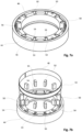
- the transceiver unit 48 is connected to a transceiver antenna 52, which surrounds the carrier 46 in the edge region on its outside, see 5 and 6 , but also 7a and 7b .
- Each magnet 50 is assigned a receptacle 54.
- a cavity 56 is provided between the carrier 46 and the magnets 50 in the respective associated receptacle 54, which is filled with casting compound after assembly.
- Epoxy resin for example, can be used as the casting compound.
- the carrier 46 is designed as a strip element. In Fig. 5 the carrier 46 is rolled out flat and in Fig. 6 the carrier 46 is shown ring-shaped, in the shape it takes when it is inserted into the carrier.
- a second annular chamber 58 (plunging ring) is also provided on the annular shoulder 38, which is U-shaped in cross section. With its U-shaped opening 58a, it points towards the top 38a of the annular shoulder 38 of the projection 40 of the motor housing 36.
- the annular shoulder 38 is arranged concentrically to the axis of rotation 30 and is U-shaped with the end faces of the legs Opening 58a is connected to the top 38a of the annular shoulder 38 of the projection 40 of the motor housing 36.
- the annular chamber 58 is firmly connected to the motor housing 36 and is also arranged in a stationary manner during operation of the centrifuge 10.
- a strip-shaped carrier 60 is glued onto the inside of a leg of the annular chamber 58 which has a U-shaped cross section.
- the carrier 60 consists of a flexible, film-shaped circuit board material, namely polyimide.
- a second transceiver unit 62 and a Hall sensor 66 are arranged on one side of the carrier 60.
- the second transceiver unit 62 is connected to a transceiver antenna 64, which includes the carrier 60 in the edge region.
- the carrier 60 is constructed analogously to the carrier 46.
- the carrier 60 is also designed as a strip element and has an electrical connection line 70 at its free end, which leads to the control.
- the annular chambers 44 and 58 each form protective chambers for the carriers 46, 60 located therein, for example against mechanical damage.
- the annular chamber 44 is important because the electrical components of the carrier 46 are protected during autoclaving.
- the second transceiver unit 62 is connected to a control unit, not shown in detail here, with an external unit for the centrifuge 10 and a display unit connected to it.
- the annular chamber 58 is arranged radially on the outside relative to the annular chamber 44 with respect to the axis of rotation 30.
- the distance between the annular chambers 44, 58 is in a range of 0.3 to 8 mm.
- the two transmitter-receiver antennas 52, 64 are arranged at the same height with respect to the axis of rotation 30 and thus overlap 100%. This achieves optimal data transmission between the transceiver antennas 52, 64 and thus between the transceiver units 48, 62. Rotor identification is also part of the data transmission.
- the Hall sensor 66 of the second carrier 60 and the magnets 50 of the first carrier 46 are arranged at the same height with respect to the axis of rotation 30 and thus overlap 100%.
- the rotor identification is transmitted in a known manner via the number of magnets and the arrangement of the magnets.
- the rotor identification and the data associated with it are safety-relevant data, these are redundantly transmitted by this embodiment from the rotor-side carrier 46 to the housing-side carrier 60 to a control device of the centrifuge 10, i.e. on the one hand through the magnets 50, which are detected by the Hall sensor 66, but also by the transceiver units 48 and 62.
- the operating data such as running cycles, running times, etc.
- the operating data are stored both for the rotor identification in a memory of the control device of the centrifuge 10 and in a memory of the transceiver unit 48.
- the first transceiver unit includes a memory in which the data of the rotor is stored, for example rotor type, maximum permissible speed, maximum permissible running time of the rotor and the like. This data is stored in permanent memory.
- a read-write memory is provided in which the operating data, such as runtime cycles, operating time, speeds driven and the like, are continuously updated.
- an acceleration sensor 68 is provided on the second carrier 60. Possible imbalances are detected via the acceleration sensor 68 and the control device can react if necessary, for example if predetermined threshold values are exceeded.
- the first transceiver unit 48 can comprise a transponder and the second transceiver unit 62 an associated reading device.
- the transceiver units 48, 62 are designed for the NFC standard.
- the rotor identification is read out from the first transmitter/receiver unit before the start of centrifugation and the rotor identification is additionally detected via the magnets 50 at startup at the latest.
- the data is compared with each other. If the data or identifier match, the operation of the centrifuge 10 continues based on the operating data assigned to the rotor identifier, maximum permissible speed, maximum service life, maximum load change, etc.
- centrifuge is switched off and a visual and acoustic alarm is triggered.
- the centrifuge 10 is also switched off and an optical alarm, such as an error message on a display, and an acoustic alarm are triggered.
- the invention is characterized in that a minimum distance can be created between the transmitting/receiving antennas 52, 64, where tolerances have little effect. Due to the overlapping arrangement of the transmitting/receiving antennas 52, 64, the data transmission is insensitive to possible tolerances in the axial direction, i.e. the position of the rotor 32 relative to the drive motor 16. In addition, due to the coaxial opposite arrangement, the carrier 46, 60 can be on one side The centripetal force acting on the transceiver unit 48 can be minimized on the cylindrical projection 32a of the rotor 32, which has the smallest possible radius, or on the projection 40 of the motor housing 36, which has the smallest possible radius.
- the invention is characterized in that there is no metal directly behind the supports that prevents the buildup of a magnetic field.
- the NFC standard creates a cost-effective and secure option for data transmission.
- the redundancy in the transmission of the engine identification significantly increases the safety of the centrifuge 10 during operation. Maximum speeds that are too high can be safely avoided in a simple manner.
- the data transmission quality is the same for all rotors 32.
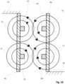
- the inventive arrangement of the carriers 46 and 60 in the direction of the axis of rotation 30 optimizes data transmission, since the rotor 32, which is generally made of metal, and the drive motor 16, which is also made of metal, the field lines of the transmitting/receiving units 48 , 62 do not affect. This is shown schematically in Fig. 10 shown, the field lines being provided with the reference number 72. Due to the arrangement, no metal is arranged in the immediate vicinity of the supports 46, 60 and the magnetic field or the electromagnetic field can build up easily and undisturbed.
Landscapes
- Engineering & Computer Science (AREA)
- Computer Networks & Wireless Communication (AREA)
- Signal Processing (AREA)
- Centrifugal Separators (AREA)
Claims (22)
- Centrifugeuse (10) avec un carter (12), dans lequel est disposé un rotor (32) pour la réception d'un échantillon à centrifuger, dans laquelle le rotor (32) repose de manière détachable sur un arbre d'entraînement, lequel est relié à un entraînement, le rotor (32) est entraîné pendant le fonctionnement de la centrifugeuse (10) par l'arbre d'entraînement (22) et tourne autour d'un axe de rotation (30), le rotor (32) présente une première unité émettrice-réceptrice côté rotor, laquelle est excitée par l'intermédiaire d'un champ électrique, ce qui a pour effet que la tension dans la première unité émettrice-réceptrice (48) est induite, la première unité émettrice-réceptrice (48) est associée à une deuxième unité émettrice-réceptrice (62) côté carter, laquelle est reliée à une source de tension, dans laquelle les deux unités émettrices-réceptrices (48, 62) sont reliées respectivement à une antenne émettrice-réceptrice (52, 64) et les unités émettrices-réceptrices (48, 62) et l'antenne émettrice-réceptrice (52, 64) sont disposées respectivement sur un support annulaire (46, 60) de manière concentrique par rapport à l'axe de rotation (30), caractérisée en ce que le support (46) de la une unité émettrice-réceptrice (48) présente un diamètre plus petit que le support (60) de l'autre unité émettrice-réceptrice (62) et l'antenne émettrice-réceptrice (52) de la une unité émettrice-réceptrice (48) chevauche par endroits l'antenne émettrice-réceptrice (64) de l'autre unité émettrice-réceptrice (62) dans une direction parallèle à l'axe de rotation (30).
- Centrifugeuse selon la revendication 1, caractérisée en ce que la surface de base d'un ou des deux supports n'est pas en appui sur du métal.
- Centrifugeuse selon la revendication 1 ou 2, caractérisée en ce que les antennes émettrices-réceptrices (52, 64) se chevauchent dans une direction parallèle à l'axe de rotation (30) de 50 %, de préférence de 70 %, en particulier de 90 %, de préférence de 95 %, de manière particulièrement préférée de 100 %.
- Centrifugeuse selon l'une quelconque des revendications précédentes, caractérisée en ce que le rotor (32) présente aussi bien un premier support (46) pour la première unité émettrice-réceptrice (48) que des aimants (50) comme identifiant pour le rotor (32), en particulier que le deuxième support (60) pour la deuxième unité émettrice-réceptrice (62) présente au moins un capteur à effet Hall (66) pour la détermination de l'identifiant de rotor du premier support (46) établie par les aimants (50).
- Centrifugeuse selon l'une quelconque des revendications précédentes, caractérisée en ce que le support (46, 60) est réalisé en forme de bande.
- Centrifugeuse selon l'une quelconque des revendications précédentes, caractérisée en ce que le support annulaire (46, 60) comprend respectivement un matériau de carte de circuits imprimés en forme de bande flexible, sur lequel l'unité émettrice-réceptrice (48, 62) et l'antenne émettrice-réceptrice (52, 64) sont appliquées, en particulier le matériau de carte de circuits imprimés flexible comprend du polyimide.
- Centrifugeuse selon l'une quelconque des revendications précédentes, caractérisée en ce que la première unité émettrice-réceptrice (48) présente une mémoire, dans laquelle les données du rotor (32) sont déposées, par exemple le type du rotor, la vitesse de rotation maximale du rotor, le temps de fonctionnement maximal du rotor, en particulier la mémoire comprend aussi bien une mémoire permanente qu'une mémoire vive.
- Centrifugeuse selon l'une quelconque des revendications précédentes, caractérisée en ce que la deuxième unité émettrice-réceptrice (62) est reliée à une unité d'évaluation et/ou une unité d'affichage.
- Centrifugeuse selon l'une quelconque des revendications précédentes, caractérisée en ce que l'antenne émettrice-réceptrice (52, 64) comprend respectivement sensiblement le support annulaire (46, 60) dans la zone de bord.
- Centrifugeuse selon l'une quelconque des revendications précédentes, caractérisée en ce que d'autres données de capteurs se trouvant sur le rotor (32) sont transmises avec le premier support (46).
- Centrifugeuse selon l'une quelconque des revendications précédentes, caractérisée en ce que la première unité émettrice-réceptrice (48) comprend un transpondeur et la deuxième unité émettrice-réceptrice (62) comprend un lecteur associé, de préférence les unités émettrices-réceptrices (48, 62) se basent sur la norme NFC.
- Centrifugeuse selon l'une quelconque des revendications précédentes, caractérisée en ce que la différence entre les rayons du premier support (46) et du deuxième support (60) se situe dans une plage de 0,3 à 8 mm.
- Centrifugeuse selon l'une quelconque des revendications précédentes, caractérisée en ce que le support (46) de la première et/ou le support (60) de la deuxième unité émettrice-réceptrice (48, 62) avec l'antenne émettrice-réceptrice (52, 64) est entouré par un carter de protection, en particulier le carter de protection (12) est réalisé sous la forme d'une chambre annulaire (44), qui est réalisée en coupe en forme de U (44a), dans laquelle de préférence l'ouverture en forme de U du carter de protection (12) pour le premier support (46) est dirigée vers le haut, en particulier dans une direction parallèle à l'axe de rotation (30), sur le rotor (32) et reliée au rotor (32) sur cette face.
- Centrifugeuse selon la revendication 13, caractérisée en ce que l'ouverture en forme de U du carter de protection (12) pour le deuxième support (60) est dirigée vers le bas, en particulier dans une direction parallèle à l'axe de rotation (30), sur le carter de moteur (36) et reliée au carter de moteur (36) sur cette face.
- Centrifugeuse selon l'une quelconque des revendications 13 ou 14, caractérisée en ce que le support (46, 60) est collé au carter de protection (12).
- Centrifugeuse selon l'une quelconque des revendications précédentes, caractérisée en ce qu'un ensemble de différents rotors (32) est prévu, en particulier chaque première antenne émettrice-réceptrice (52) des rotors (32) est disposée à la même hauteur par rapport à l'axe de rotation (30).
- Centrifugeuse selon la revendication 15 ou 16, caractérisée en ce que chaque rotor (32) présente une partie saillante cylindrique (32a) tournée vers le bas sur le moteur d'entraînement, qui est disposée de manière concentrique par rapport à l'axe de rotation (30) de l'arbre d'entraînement (22), dans lequelle la distance par rapport à un siège de rotor, avec lequelle le rotor (32) repose sur l'arbre d'entraînement (22), est respectivement la même que par rapport à l'extrémité libre de la partie saillante (32a).
- Procédé pour faire fonctionner une centrifugeuse (10) selon la revendication 4, en particulier et une autre des revendications précédentes, caractérisé en ce que des premières données de la première unité émettrice-réceptrice (48) sont lues pendant le fonctionnement par la deuxième unité émettrice-réceptrice (62), des deuxièmes données sont acquises par un capteur du deuxième support (60) par l'intermédiaire des aimants (50) du premier support (46), les premières et deuxièmes données sont comparées les unes aux autres, lorsque les premières et deuxièmes données concordent le fonctionnement de la centrifugeuse (10) est poursuivi.
- Procédé selon la revendication 18, caractérisé en ce que lorsque les premières et deuxièmes données ne concordent pas la centrifugeuse (10) est éteinte.
- Procédé selon la revendication 18 ou 19, caractérisé en ce qu'en ce lorsque les premières et deuxièmes données ne concordent pas une alarme optique et/ou acoustique est déclenchée.
- Procédé selon l'une quelconque des revendications 18 à 20, caractérisé en ce qu'un identifiant de rotor provenant aussi bien de la première unité émettrice-réceptrice (48) que des aimants (50) du premier support (46) est lu, des vitesses maximales correspondantes de la centrifugeuse (10), lesquelles ne sont pas dépassées lors du fonctionnement, sont associées à cet identifiant de rotor lu.
- Procédé selon l'une quelconque des revendications 18 à 21, caractérisé en ce que lorsqu'une valeur de seuil prédéfinie en ce qui concerne les données fournies par un capteur d'accélération (68) est dépassée, la centrifugeuse (10) est éteinte.
Applications Claiming Priority (2)
| Application Number | Priority Date | Filing Date | Title |
|---|---|---|---|
| DE102019121598.6A DE102019121598A1 (de) | 2019-08-09 | 2019-08-09 | Zentrifuge |
| PCT/EP2020/072200 WO2021028325A1 (fr) | 2019-08-09 | 2020-08-06 | Centrifugeuse |
Publications (2)
| Publication Number | Publication Date |
|---|---|
| EP4010124A1 EP4010124A1 (fr) | 2022-06-15 |
| EP4010124B1 true EP4010124B1 (fr) | 2023-10-04 |
Family
ID=72050845
Family Applications (1)
| Application Number | Title | Priority Date | Filing Date |
|---|---|---|---|
| EP20754704.3A Active EP4010124B1 (fr) | 2019-08-09 | 2020-08-06 | Centrifugeuse |
Country Status (8)
| Country | Link |
|---|---|
| US (1) | US20220266264A1 (fr) |
| EP (1) | EP4010124B1 (fr) |
| JP (1) | JP7536859B2 (fr) |
| KR (1) | KR102915130B1 (fr) |
| CN (1) | CN114728297B (fr) |
| DE (1) | DE102019121598A1 (fr) |
| PL (1) | PL4010124T4 (fr) |
| WO (1) | WO2021028325A1 (fr) |
Families Citing this family (2)
| Publication number | Priority date | Publication date | Assignee | Title |
|---|---|---|---|---|
| WO2022232781A1 (fr) * | 2021-04-30 | 2022-11-03 | Laboratory Corporation Of America Holdings | Ensemble tube à centrifuger, rotor à centrifuger et centrifugeuse |
| KR20230168305A (ko) | 2022-06-07 | 2023-12-14 | 김택민 | 중력의 작용과 물질밀림작용과 물질새치기작용과 물질폭발작용을 유도하여 비중이 가벼운 유체성 물질분자와 비중이 무거운 유체성 물질분자를 분리하여 가공하도록 구성되는 원심분리기 및 이를 이용하여 비중이 가벼운 유체성 물질분자와 비중이 무거운 유체성 물질분자를 분리가공하여 추출하는 자연친화적인 친환경 공법 |
Family Cites Families (33)
| Publication number | Priority date | Publication date | Assignee | Title |
|---|---|---|---|---|
| FR2428821A1 (fr) * | 1978-06-12 | 1980-01-11 | Electricite De France | Dispositif de transmission inductif sans contact de signal numerique pour appareillage tournant |
| SU1704840A1 (ru) * | 1988-07-18 | 1992-01-15 | Московское научно-производственное объединение "Биофизприбор" | Устройство дл контрол центрифуги |
| DE69026039T2 (de) * | 1989-12-08 | 1996-08-22 | Hitachi Koki Kk | System zum Festlegen der Betriebsbedingungen von Zentrifugenrotoren |
| JP2514554B2 (ja) * | 1992-12-28 | 1996-07-10 | 株式会社久保田製作所 | 遠心機 |
| RU2096841C1 (ru) * | 1993-08-04 | 1997-11-20 | Постников Виктор Викторович | Устройство для широкодиапазонного измерения характеристик ионизирующих излучений с подвижным детектором |
| US5518493A (en) * | 1994-07-07 | 1996-05-21 | Beckman Instruments, Inc. | Automatic rotor identification based on a rotor-transmitted signal |
| JP2004048449A (ja) * | 2002-07-12 | 2004-02-12 | Seiko Instruments Inc | 携帯型送受信機 |
| JP3711111B2 (ja) * | 2003-01-23 | 2005-10-26 | 三菱電機株式会社 | リニアモータ |
| DE102004002110A1 (de) * | 2004-01-14 | 2005-08-11 | Hermle Labortechnik Gmbh | Zentrifuge |
| JP2007090325A (ja) | 2005-09-01 | 2007-04-12 | Hitachi Koki Co Ltd | 遠心分離機 |
| JP2009240886A (ja) | 2008-03-31 | 2009-10-22 | Hitachi Koki Co Ltd | 遠心機 |
| JP2009247084A (ja) * | 2008-03-31 | 2009-10-22 | Hitachi Ltd | 回転電機および自動車 |
| JP2009261055A (ja) * | 2008-04-14 | 2009-11-05 | Seiko Epson Corp | 非接触電力供給方法および非接触電力供給装置 |
| JP5286011B2 (ja) * | 2008-09-30 | 2013-09-11 | 株式会社日立製作所 | 回転電機 |
| JP5551392B2 (ja) * | 2009-08-18 | 2014-07-16 | シリコン・バレイ・マイクロ・エム・コーポレーション | Rfidロータ・マグネット位置検出を備えたブラシレス直流モータ、ブラシレス直流モータシステムおよびそれらの校正方法 |
| FR2951965B1 (fr) * | 2009-11-04 | 2012-04-06 | Bms Internat | Centrifugeuse integrant des moyens tachymetriques montes dans une partie superieure de l'enceinte, en particulier montes sur le couvercle |
| CA2692995C (fr) * | 2010-02-01 | 2016-06-28 | Kudu Industries Inc. | Systeme et methode de chauffage par induction d'un rotor helicoidal utilisant une bobine |
| TWI433389B (zh) * | 2010-04-22 | 2014-04-01 | Taiwan Lamination Ind Inc | Packaging bag with radio frequency identification capability and its manufacturing method |
| DE102011000651A1 (de) * | 2011-02-11 | 2012-08-16 | Andreas Voss | Flugkörper |
| DE102011106578A1 (de) * | 2011-06-16 | 2012-12-20 | Andreas Stihl Ag & Co. Kg | Akkubetriebener Elektromotor in einem Arbeitsgerät |
| JP5656766B2 (ja) * | 2011-08-03 | 2015-01-21 | 太平洋工業株式会社 | 回転体用無線通信システム |
| JP5639095B2 (ja) * | 2012-01-26 | 2014-12-10 | 太平洋工業株式会社 | 回転体用無線通信システム |
| EP2623206A1 (fr) * | 2012-02-01 | 2013-08-07 | Baumer Electric AG | Centrifugeuse |
| JP2015020123A (ja) * | 2013-07-19 | 2015-02-02 | 日立工機株式会社 | 遠心機 |
| JP2013234571A (ja) * | 2013-08-28 | 2013-11-21 | Taruno Kazuo | 未来の別の美瑛街に出来る世界遺産を目指す為の永遠に壊さないクリスタルダイヤ硝子ビルに伴う終身介護システムの著作権原本。 |
| DE102014116527B4 (de) * | 2014-11-12 | 2020-01-23 | Andreas Hettich Gmbh & Co. Kg | Zentrifuge und Verfahren zur Erfassung von Unwuchten in der Zentrifuge |
| CN104538751B (zh) * | 2014-12-31 | 2017-05-17 | 四川中光防雷科技股份有限公司 | 柔性接地装置与方法及其系统 |
| CN206315926U (zh) * | 2016-12-13 | 2017-07-11 | 盐城新安洲药业有限公司 | 一种智能台式离心机 |
| EP3689470A1 (fr) * | 2017-06-15 | 2020-08-05 | Alfa Laval Corporate AB | Séparateur centrifuge et son procédé de fonctionnement |
| DE102017211490A1 (de) * | 2017-07-06 | 2019-01-10 | Robert Bosch Gmbh | Drehwinkelsensoranordnung, LiDAR-System, Arbeitsvorrichtung und Betriebsverfahren für ein LiDAR-System |
| EP3505258B1 (fr) * | 2018-01-02 | 2020-09-02 | Sigma Laborzentrifugen GmbH | Centrifugeuse de laboratoire |
| DE102018101457A1 (de) * | 2018-01-23 | 2019-07-25 | Eppendorf Ag | Verfahren und Vorrichtung zur Überwachung der Drehzahl eines Elements |
| DE202018101760U1 (de) * | 2018-03-28 | 2019-07-01 | Sigma Laborzentrifugen Gmbh | Laborzentrifuge und Zentrifugenbehälter für eine Laborzentrifuge |
-
2019
- 2019-08-09 DE DE102019121598.6A patent/DE102019121598A1/de active Pending
-
2020
- 2020-08-06 EP EP20754704.3A patent/EP4010124B1/fr active Active
- 2020-08-06 KR KR1020227006797A patent/KR102915130B1/ko active Active
- 2020-08-06 PL PL20754704.3T patent/PL4010124T4/pl unknown
- 2020-08-06 US US17/633,982 patent/US20220266264A1/en active Pending
- 2020-08-06 WO PCT/EP2020/072200 patent/WO2021028325A1/fr not_active Ceased
- 2020-08-06 JP JP2022507837A patent/JP7536859B2/ja active Active
- 2020-08-06 CN CN202080066824.2A patent/CN114728297B/zh active Active
Also Published As
| Publication number | Publication date |
|---|---|
| CN114728297B (zh) | 2023-11-03 |
| JP7536859B2 (ja) | 2024-08-20 |
| WO2021028325A1 (fr) | 2021-02-18 |
| PL4010124T3 (pl) | 2024-07-01 |
| CN114728297A (zh) | 2022-07-08 |
| KR102915130B1 (ko) | 2026-01-19 |
| DE102019121598A1 (de) | 2021-02-11 |
| PL4010124T4 (pl) | 2024-07-01 |
| US20220266264A1 (en) | 2022-08-25 |
| EP4010124A1 (fr) | 2022-06-15 |
| JP2022543484A (ja) | 2022-10-12 |
| KR20220042419A (ko) | 2022-04-05 |
Similar Documents
| Publication | Publication Date | Title |
|---|---|---|
| EP1959240B1 (fr) | Encodeur et son procédé de fonctionnement | |
| EP3469224B1 (fr) | Palier lisse, élément de glissement en matière plastique, système et procédé de détection de l'usure | |
| DE102011007981B4 (de) | Drehmelder mit Lokalisierungsmerkmal | |
| EP1607720B1 (fr) | Capteur d'angle de braquage | |
| DE102008060262B4 (de) | Sensorsystem für elektrische Maschinen mit mehrpoligen Sensormagneten und mindestens einem Hall-IC | |
| EP3683551B1 (fr) | Unité de balayage pour un dispositif de mesure d'angle | |
| EP1408305A2 (fr) | Dispositif de mesure de l'angle absolu d'un arbre tournant | |
| EP3824250B1 (fr) | Système de mesure d'angle de rotation | |
| EP2520807B1 (fr) | Pompe à vide avec rotor | |
| EP3517210B1 (fr) | Procédé et dispositif de surveillance de la vitesse de rotation d'un élément | |
| EP4010124A1 (fr) | Centrifugeuse | |
| EP2808983B1 (fr) | Encodeur pour un capteur rotatif compact et moteur électrique doté d'un capteur rotatif compact | |
| WO2018121912A1 (fr) | Moteur électrique sans balais | |
| EP0344443A2 (fr) | Centrifugeuse | |
| EP3640601B1 (fr) | Dispositif de mesure de position et procédé de fonctionnement d'un dispositif de mesure de position | |
| EP3683552B1 (fr) | Unité de balayage pour un dispositif de mesure d'angle | |
| DE102019116015A1 (de) | Axialflussmotor mit redundanter Rotorlageerfassung für ein LIDAR-System | |
| EP2060793B1 (fr) | Pompe à vide | |
| EP2130289B1 (fr) | Moteur électrique | |
| DE4208059A1 (de) | Zentrifuge | |
| DE102008009018A1 (de) | Elektromotor | |
| WO2019141443A1 (fr) | Machine fluidique | |
| DE212018000196U1 (de) | Bearbeitungsspindel | |
| EP4086584B1 (fr) | Module doté d'un capteur rotatif et d'un manchon de tolérance | |
| EP1703983B1 (fr) | Centrifugeuse a identification de rotor au moyen d'un transpondeur |
Legal Events
| Date | Code | Title | Description |
|---|---|---|---|
| STAA | Information on the status of an ep patent application or granted ep patent |
Free format text: STATUS: UNKNOWN |
|
| STAA | Information on the status of an ep patent application or granted ep patent |
Free format text: STATUS: THE INTERNATIONAL PUBLICATION HAS BEEN MADE |
|
| TPAC | Observations filed by third parties |
Free format text: ORIGINAL CODE: EPIDOSNTIPA |
|
| PUAI | Public reference made under article 153(3) epc to a published international application that has entered the european phase |
Free format text: ORIGINAL CODE: 0009012 |
|
| STAA | Information on the status of an ep patent application or granted ep patent |
Free format text: STATUS: REQUEST FOR EXAMINATION WAS MADE |
|
| 17P | Request for examination filed |
Effective date: 20220301 |
|
| AK | Designated contracting states |
Kind code of ref document: A1 Designated state(s): AL AT BE BG CH CY CZ DE DK EE ES FI FR GB GR HR HU IE IS IT LI LT LU LV MC MK MT NL NO PL PT RO RS SE SI SK SM TR |
|
| DAV | Request for validation of the european patent (deleted) | ||
| DAX | Request for extension of the european patent (deleted) | ||
| REG | Reference to a national code |
Ref country code: DE Free format text: PREVIOUS MAIN CLASS: B04B0013000000 Ipc: B04B0009140000 Ref country code: DE Ref legal event code: R079 Ref document number: 502020005541 Country of ref document: DE Free format text: PREVIOUS MAIN CLASS: B04B0013000000 Ipc: B04B0009140000 |
|
| GRAP | Despatch of communication of intention to grant a patent |
Free format text: ORIGINAL CODE: EPIDOSNIGR1 |
|
| RIC1 | Information provided on ipc code assigned before grant |
Ipc: B04B 13/00 20060101ALI20230302BHEP Ipc: B04B 9/14 20060101AFI20230302BHEP |
|
| STAA | Information on the status of an ep patent application or granted ep patent |
Free format text: STATUS: GRANT OF PATENT IS INTENDED |
|
| INTG | Intention to grant announced |
Effective date: 20230406 |
|
| GRAJ | Information related to disapproval of communication of intention to grant by the applicant or resumption of examination proceedings by the epo deleted |
Free format text: ORIGINAL CODE: EPIDOSDIGR1 |
|
| STAA | Information on the status of an ep patent application or granted ep patent |
Free format text: STATUS: REQUEST FOR EXAMINATION WAS MADE |
|
| GRAS | Grant fee paid |
Free format text: ORIGINAL CODE: EPIDOSNIGR3 |
|
| STAA | Information on the status of an ep patent application or granted ep patent |
Free format text: STATUS: GRANT OF PATENT IS INTENDED |
|
| GRAP | Despatch of communication of intention to grant a patent |
Free format text: ORIGINAL CODE: EPIDOSNIGR1 |
|
| INTC | Intention to grant announced (deleted) | ||
| INTG | Intention to grant announced |
Effective date: 20230801 |
|
| GRAA | (expected) grant |
Free format text: ORIGINAL CODE: 0009210 |
|
| STAA | Information on the status of an ep patent application or granted ep patent |
Free format text: STATUS: THE PATENT HAS BEEN GRANTED |
|
| AK | Designated contracting states |
Kind code of ref document: B1 Designated state(s): AL AT BE BG CH CY CZ DE DK EE ES FI FR GB GR HR HU IE IS IT LI LT LU LV MC MK MT NL NO PL PT RO RS SE SI SK SM TR |
|
| REG | Reference to a national code |
Ref country code: GB Ref legal event code: FG4D Free format text: NOT ENGLISH |
|
| REG | Reference to a national code |
Ref country code: CH Ref legal event code: EP |
|
| REG | Reference to a national code |
Ref country code: IE Ref legal event code: FG4D Free format text: LANGUAGE OF EP DOCUMENT: GERMAN |
|
| REG | Reference to a national code |
Ref country code: DE Ref legal event code: R096 Ref document number: 502020005541 Country of ref document: DE |
|
| P01 | Opt-out of the competence of the unified patent court (upc) registered |
Effective date: 20231023 |
|
| REG | Reference to a national code |
Ref country code: LT Ref legal event code: MG9D |
|
| REG | Reference to a national code |
Ref country code: NL Ref legal event code: MP Effective date: 20231004 |
|
| PG25 | Lapsed in a contracting state [announced via postgrant information from national office to epo] |
Ref country code: NL Free format text: LAPSE BECAUSE OF FAILURE TO SUBMIT A TRANSLATION OF THE DESCRIPTION OR TO PAY THE FEE WITHIN THE PRESCRIBED TIME-LIMIT Effective date: 20231004 |
|
| PG25 | Lapsed in a contracting state [announced via postgrant information from national office to epo] |
Ref country code: GR Free format text: LAPSE BECAUSE OF FAILURE TO SUBMIT A TRANSLATION OF THE DESCRIPTION OR TO PAY THE FEE WITHIN THE PRESCRIBED TIME-LIMIT Effective date: 20240105 |
|
| PG25 | Lapsed in a contracting state [announced via postgrant information from national office to epo] |
Ref country code: IS Free format text: LAPSE BECAUSE OF FAILURE TO SUBMIT A TRANSLATION OF THE DESCRIPTION OR TO PAY THE FEE WITHIN THE PRESCRIBED TIME-LIMIT Effective date: 20240204 |
|
| PG25 | Lapsed in a contracting state [announced via postgrant information from national office to epo] |
Ref country code: LT Free format text: LAPSE BECAUSE OF FAILURE TO SUBMIT A TRANSLATION OF THE DESCRIPTION OR TO PAY THE FEE WITHIN THE PRESCRIBED TIME-LIMIT Effective date: 20231004 |
|
| PG25 | Lapsed in a contracting state [announced via postgrant information from national office to epo] |
Ref country code: ES Free format text: LAPSE BECAUSE OF FAILURE TO SUBMIT A TRANSLATION OF THE DESCRIPTION OR TO PAY THE FEE WITHIN THE PRESCRIBED TIME-LIMIT Effective date: 20231004 |
|
| PG25 | Lapsed in a contracting state [announced via postgrant information from national office to epo] |
Ref country code: LT Free format text: LAPSE BECAUSE OF FAILURE TO SUBMIT A TRANSLATION OF THE DESCRIPTION OR TO PAY THE FEE WITHIN THE PRESCRIBED TIME-LIMIT Effective date: 20231004 Ref country code: IS Free format text: LAPSE BECAUSE OF FAILURE TO SUBMIT A TRANSLATION OF THE DESCRIPTION OR TO PAY THE FEE WITHIN THE PRESCRIBED TIME-LIMIT Effective date: 20240204 Ref country code: GR Free format text: LAPSE BECAUSE OF FAILURE TO SUBMIT A TRANSLATION OF THE DESCRIPTION OR TO PAY THE FEE WITHIN THE PRESCRIBED TIME-LIMIT Effective date: 20240105 Ref country code: ES Free format text: LAPSE BECAUSE OF FAILURE TO SUBMIT A TRANSLATION OF THE DESCRIPTION OR TO PAY THE FEE WITHIN THE PRESCRIBED TIME-LIMIT Effective date: 20231004 Ref country code: BG Free format text: LAPSE BECAUSE OF FAILURE TO SUBMIT A TRANSLATION OF THE DESCRIPTION OR TO PAY THE FEE WITHIN THE PRESCRIBED TIME-LIMIT Effective date: 20240104 Ref country code: PT Free format text: LAPSE BECAUSE OF FAILURE TO SUBMIT A TRANSLATION OF THE DESCRIPTION OR TO PAY THE FEE WITHIN THE PRESCRIBED TIME-LIMIT Effective date: 20240205 |
|
| PG25 | Lapsed in a contracting state [announced via postgrant information from national office to epo] |
Ref country code: SE Free format text: LAPSE BECAUSE OF FAILURE TO SUBMIT A TRANSLATION OF THE DESCRIPTION OR TO PAY THE FEE WITHIN THE PRESCRIBED TIME-LIMIT Effective date: 20231004 Ref country code: RS Free format text: LAPSE BECAUSE OF FAILURE TO SUBMIT A TRANSLATION OF THE DESCRIPTION OR TO PAY THE FEE WITHIN THE PRESCRIBED TIME-LIMIT Effective date: 20231004 Ref country code: NO Free format text: LAPSE BECAUSE OF FAILURE TO SUBMIT A TRANSLATION OF THE DESCRIPTION OR TO PAY THE FEE WITHIN THE PRESCRIBED TIME-LIMIT Effective date: 20240104 Ref country code: LV Free format text: LAPSE BECAUSE OF FAILURE TO SUBMIT A TRANSLATION OF THE DESCRIPTION OR TO PAY THE FEE WITHIN THE PRESCRIBED TIME-LIMIT Effective date: 20231004 Ref country code: HR Free format text: LAPSE BECAUSE OF FAILURE TO SUBMIT A TRANSLATION OF THE DESCRIPTION OR TO PAY THE FEE WITHIN THE PRESCRIBED TIME-LIMIT Effective date: 20231004 |
|
| REG | Reference to a national code |
Ref country code: DE Ref legal event code: R097 Ref document number: 502020005541 Country of ref document: DE |
|
| PG25 | Lapsed in a contracting state [announced via postgrant information from national office to epo] |
Ref country code: DK Free format text: LAPSE BECAUSE OF FAILURE TO SUBMIT A TRANSLATION OF THE DESCRIPTION OR TO PAY THE FEE WITHIN THE PRESCRIBED TIME-LIMIT Effective date: 20231004 |
|
| PG25 | Lapsed in a contracting state [announced via postgrant information from national office to epo] |
Ref country code: CZ Free format text: LAPSE BECAUSE OF FAILURE TO SUBMIT A TRANSLATION OF THE DESCRIPTION OR TO PAY THE FEE WITHIN THE PRESCRIBED TIME-LIMIT Effective date: 20231004 |
|
| PG25 | Lapsed in a contracting state [announced via postgrant information from national office to epo] |
Ref country code: SK Free format text: LAPSE BECAUSE OF FAILURE TO SUBMIT A TRANSLATION OF THE DESCRIPTION OR TO PAY THE FEE WITHIN THE PRESCRIBED TIME-LIMIT Effective date: 20231004 |
|
| PG25 | Lapsed in a contracting state [announced via postgrant information from national office to epo] |
Ref country code: SM Free format text: LAPSE BECAUSE OF FAILURE TO SUBMIT A TRANSLATION OF THE DESCRIPTION OR TO PAY THE FEE WITHIN THE PRESCRIBED TIME-LIMIT Effective date: 20231004 Ref country code: SK Free format text: LAPSE BECAUSE OF FAILURE TO SUBMIT A TRANSLATION OF THE DESCRIPTION OR TO PAY THE FEE WITHIN THE PRESCRIBED TIME-LIMIT Effective date: 20231004 Ref country code: RO Free format text: LAPSE BECAUSE OF FAILURE TO SUBMIT A TRANSLATION OF THE DESCRIPTION OR TO PAY THE FEE WITHIN THE PRESCRIBED TIME-LIMIT Effective date: 20231004 Ref country code: IT Free format text: LAPSE BECAUSE OF FAILURE TO SUBMIT A TRANSLATION OF THE DESCRIPTION OR TO PAY THE FEE WITHIN THE PRESCRIBED TIME-LIMIT Effective date: 20231004 Ref country code: EE Free format text: LAPSE BECAUSE OF FAILURE TO SUBMIT A TRANSLATION OF THE DESCRIPTION OR TO PAY THE FEE WITHIN THE PRESCRIBED TIME-LIMIT Effective date: 20231004 Ref country code: DK Free format text: LAPSE BECAUSE OF FAILURE TO SUBMIT A TRANSLATION OF THE DESCRIPTION OR TO PAY THE FEE WITHIN THE PRESCRIBED TIME-LIMIT Effective date: 20231004 Ref country code: CZ Free format text: LAPSE BECAUSE OF FAILURE TO SUBMIT A TRANSLATION OF THE DESCRIPTION OR TO PAY THE FEE WITHIN THE PRESCRIBED TIME-LIMIT Effective date: 20231004 |
|
| PLBE | No opposition filed within time limit |
Free format text: ORIGINAL CODE: 0009261 |
|
| STAA | Information on the status of an ep patent application or granted ep patent |
Free format text: STATUS: NO OPPOSITION FILED WITHIN TIME LIMIT |
|
| 26N | No opposition filed |
Effective date: 20240705 |
|
| PG25 | Lapsed in a contracting state [announced via postgrant information from national office to epo] |
Ref country code: SI Free format text: LAPSE BECAUSE OF FAILURE TO SUBMIT A TRANSLATION OF THE DESCRIPTION OR TO PAY THE FEE WITHIN THE PRESCRIBED TIME-LIMIT Effective date: 20231004 |
|
| PG25 | Lapsed in a contracting state [announced via postgrant information from national office to epo] |
Ref country code: SI Free format text: LAPSE BECAUSE OF FAILURE TO SUBMIT A TRANSLATION OF THE DESCRIPTION OR TO PAY THE FEE WITHIN THE PRESCRIBED TIME-LIMIT Effective date: 20231004 |
|
| PGFP | Annual fee paid to national office [announced via postgrant information from national office to epo] |
Ref country code: IE Payment date: 20241024 Year of fee payment: 5 |
|
| REG | Reference to a national code |
Ref country code: DE Ref legal event code: R081 Ref document number: 502020005541 Country of ref document: DE Owner name: ANDREAS HETTICH GMBH, DE Free format text: FORMER OWNER: ANDREAS HETTICH GMBH & CO. KG, 78532 TUTTLINGEN, DE |
|
| REG | Reference to a national code |
Ref country code: CH Ref legal event code: PL |
|
| PG25 | Lapsed in a contracting state [announced via postgrant information from national office to epo] |
Ref country code: LU Free format text: LAPSE BECAUSE OF NON-PAYMENT OF DUE FEES Effective date: 20240806 |
|
| PG25 | Lapsed in a contracting state [announced via postgrant information from national office to epo] |
Ref country code: MC Free format text: LAPSE BECAUSE OF FAILURE TO SUBMIT A TRANSLATION OF THE DESCRIPTION OR TO PAY THE FEE WITHIN THE PRESCRIBED TIME-LIMIT Effective date: 20231004 Ref country code: CH Free format text: LAPSE BECAUSE OF NON-PAYMENT OF DUE FEES Effective date: 20240831 |
|
| REG | Reference to a national code |
Ref country code: BE Ref legal event code: MM Effective date: 20240831 |
|
| PG25 | Lapsed in a contracting state [announced via postgrant information from national office to epo] |
Ref country code: BE Free format text: LAPSE BECAUSE OF NON-PAYMENT OF DUE FEES Effective date: 20240831 |
|
| PG25 | Lapsed in a contracting state [announced via postgrant information from national office to epo] |
Ref country code: FI Free format text: LAPSE BECAUSE OF FAILURE TO SUBMIT A TRANSLATION OF THE DESCRIPTION OR TO PAY THE FEE WITHIN THE PRESCRIBED TIME-LIMIT Effective date: 20231004 |
|
| PGFP | Annual fee paid to national office [announced via postgrant information from national office to epo] |
Ref country code: DE Payment date: 20250822 Year of fee payment: 6 |
|
| PGFP | Annual fee paid to national office [announced via postgrant information from national office to epo] |
Ref country code: PL Payment date: 20250725 Year of fee payment: 6 |
|
| PGFP | Annual fee paid to national office [announced via postgrant information from national office to epo] |
Ref country code: GB Payment date: 20250822 Year of fee payment: 6 |
|
| PGFP | Annual fee paid to national office [announced via postgrant information from national office to epo] |
Ref country code: AT Payment date: 20251020 Year of fee payment: 5 Ref country code: FR Payment date: 20250821 Year of fee payment: 6 |
|
| PG25 | Lapsed in a contracting state [announced via postgrant information from national office to epo] |
Ref country code: CY Free format text: LAPSE BECAUSE OF FAILURE TO SUBMIT A TRANSLATION OF THE DESCRIPTION OR TO PAY THE FEE WITHIN THE PRESCRIBED TIME-LIMIT; INVALID AB INITIO Effective date: 20200806 |
|
| PG25 | Lapsed in a contracting state [announced via postgrant information from national office to epo] |
Ref country code: HU Free format text: LAPSE BECAUSE OF FAILURE TO SUBMIT A TRANSLATION OF THE DESCRIPTION OR TO PAY THE FEE WITHIN THE PRESCRIBED TIME-LIMIT; INVALID AB INITIO Effective date: 20200806 |