EP4010132B1 - Machine à enrouler - Google Patents
Machine à enrouler Download PDFInfo
- Publication number
- EP4010132B1 EP4010132B1 EP21746744.8A EP21746744A EP4010132B1 EP 4010132 B1 EP4010132 B1 EP 4010132B1 EP 21746744 A EP21746744 A EP 21746744A EP 4010132 B1 EP4010132 B1 EP 4010132B1
- Authority
- EP
- European Patent Office
- Prior art keywords
- coupling
- winding machine
- coupling element
- sensor
- machine according
- Prior art date
- Legal status (The legal status is an assumption and is not a legal conclusion. Google has not performed a legal analysis and makes no representation as to the accuracy of the status listed.)
- Active
Links
Images



Classifications
-
- B—PERFORMING OPERATIONS; TRANSPORTING
- B21—MECHANICAL METAL-WORKING WITHOUT ESSENTIALLY REMOVING MATERIAL; PUNCHING METAL
- B21C—MANUFACTURE OF METAL SHEETS, WIRE, RODS, TUBES, PROFILES OR LIKE SEMI-MANUFACTURED PRODUCTS OTHERWISE THAN BY ROLLING; AUXILIARY OPERATIONS USED IN CONNECTION WITH METAL-WORKING WITHOUT ESSENTIALLY REMOVING MATERIAL
- B21C47/00—Winding-up, coiling or winding-off metal wire, metal band or other flexible metal material characterised by features relevant to metal processing only
- B21C47/02—Winding-up or coiling
- B21C47/04—Winding-up or coiling on or in reels or drums, without using a moving guide
-
- B—PERFORMING OPERATIONS; TRANSPORTING
- B21—MECHANICAL METAL-WORKING WITHOUT ESSENTIALLY REMOVING MATERIAL; PUNCHING METAL
- B21C—MANUFACTURE OF METAL SHEETS, WIRE, RODS, TUBES, PROFILES OR LIKE SEMI-MANUFACTURED PRODUCTS OTHERWISE THAN BY ROLLING; AUXILIARY OPERATIONS USED IN CONNECTION WITH METAL-WORKING WITHOUT ESSENTIALLY REMOVING MATERIAL
- B21C47/00—Winding-up, coiling or winding-off metal wire, metal band or other flexible metal material characterised by features relevant to metal processing only
- B21C47/16—Unwinding or uncoiling
- B21C47/18—Unwinding or uncoiling from reels or drums
-
- B—PERFORMING OPERATIONS; TRANSPORTING
- B21—MECHANICAL METAL-WORKING WITHOUT ESSENTIALLY REMOVING MATERIAL; PUNCHING METAL
- B21C—MANUFACTURE OF METAL SHEETS, WIRE, RODS, TUBES, PROFILES OR LIKE SEMI-MANUFACTURED PRODUCTS OTHERWISE THAN BY ROLLING; AUXILIARY OPERATIONS USED IN CONNECTION WITH METAL-WORKING WITHOUT ESSENTIALLY REMOVING MATERIAL
- B21C47/00—Winding-up, coiling or winding-off metal wire, metal band or other flexible metal material characterised by features relevant to metal processing only
- B21C47/24—Transferring coils to or from winding apparatus or to or from operative position therein; Preventing uncoiling during transfer
- B21C47/242—Devices for swinging the coil from horizontal to vertical, or vice versa
-
- B—PERFORMING OPERATIONS; TRANSPORTING
- B65—CONVEYING; PACKING; STORING; HANDLING THIN OR FILAMENTARY MATERIAL
- B65H—HANDLING THIN OR FILAMENTARY MATERIAL, e.g. SHEETS, WEBS, CABLES
- B65H18/00—Winding webs
- B65H18/02—Supporting web roll
- B65H18/023—Supporting web roll on its outer circumference
-
- B—PERFORMING OPERATIONS; TRANSPORTING
- B65—CONVEYING; PACKING; STORING; HANDLING THIN OR FILAMENTARY MATERIAL
- B65H—HANDLING THIN OR FILAMENTARY MATERIAL, e.g. SHEETS, WEBS, CABLES
- B65H18/00—Winding webs
- B65H18/02—Supporting web roll
- B65H18/028—Both ends type
-
- B—PERFORMING OPERATIONS; TRANSPORTING
- B65—CONVEYING; PACKING; STORING; HANDLING THIN OR FILAMENTARY MATERIAL
- B65H—HANDLING THIN OR FILAMENTARY MATERIAL, e.g. SHEETS, WEBS, CABLES
- B65H23/00—Registering, tensioning, smoothing or guiding webs
- B65H23/02—Registering, tensioning, smoothing or guiding webs transversely
- B65H23/022—Registering, tensioning, smoothing or guiding webs transversely by tentering devices
- B65H23/025—Registering, tensioning, smoothing or guiding webs transversely by tentering devices by rollers
-
- B—PERFORMING OPERATIONS; TRANSPORTING
- B65—CONVEYING; PACKING; STORING; HANDLING THIN OR FILAMENTARY MATERIAL
- B65H—HANDLING THIN OR FILAMENTARY MATERIAL, e.g. SHEETS, WEBS, CABLES
- B65H2301/00—Handling processes for sheets or webs
- B65H2301/40—Type of handling process
- B65H2301/41—Winding, unwinding
- B65H2301/413—Supporting web roll
- B65H2301/4131—Support with vertical axis
-
- B—PERFORMING OPERATIONS; TRANSPORTING
- B65—CONVEYING; PACKING; STORING; HANDLING THIN OR FILAMENTARY MATERIAL
- B65H—HANDLING THIN OR FILAMENTARY MATERIAL, e.g. SHEETS, WEBS, CABLES
- B65H2402/00—Constructional details of the handling apparatus
- B65H2402/30—Supports; Subassemblies; Mountings thereof
- B65H2402/31—Pivoting support means
-
- B—PERFORMING OPERATIONS; TRANSPORTING
- B65—CONVEYING; PACKING; STORING; HANDLING THIN OR FILAMENTARY MATERIAL
- B65H—HANDLING THIN OR FILAMENTARY MATERIAL, e.g. SHEETS, WEBS, CABLES
- B65H2403/00—Power transmission; Driving means
- B65H2403/70—Clutches; Couplings
- B65H2403/73—Couplings
Definitions
- the invention relates to a winding machine for winding and/or unwinding band or strip-shaped material according to the preamble of claim 1 and a method according to the preamble of claim 13.
- Tape or strip-shaped material is used in industry for many purposes. For example, by punching the band or strip-shaped material, e.g. a metal strip, a wide variety of components can be produced, including for the electrical industry.
- the band or strip-shaped material is usually delivered on drums or pallets and must first be unwound from the drum or pallet for the punching process, for example. Accordingly, the reverse happens when the material is manufactured and the material is wound up. After production, the material is then wound onto a drum or pallet, for example, for transport to a customer.
- the drum is usually rotated around a horizontal axis or the pallet around a vertical axis so that the band or strip-shaped material is wound up or unwound can be.
- the prior art there are devices which, for example, have a horizontal or a vertical axis of rotation and thus wind or unwind the band-shaped material.
- a horizontal unwinder for unwinding band or strip-shaped material from at least one horizontally lying coil with a rotary drive and a guide device is known.
- a sensor device is provided for scanning the height of the coils and can be adjusted depending on the detected height. This means that the unwinder can be adjusted to the height of the material conveyed by the spool depending on the material used.
- a feeding system for a strip to a production line is known, with the spool being arranged on a turntable or a turntable.
- the rotating unit is not pivotably mounted.
- the prior art in particular in the applicant's product portfolio, also discloses devices which have both possible applications ( pallet and drum) in realize a device (Leicht Stanzautomation GmbH, https://stanzautomation.de/de/maschinen/ptw-130, last access: June 30, 2020 ).
- a pallet mode the pallet is wound up and/or unwound with respect to a vertical axis using a turntable.
- By pivoting the turntable it is possible to convert the device into a drum mode, so that a drum can be wound up and/or unwound around a horizontal axis.
- the turntable is engaged or disengaged from a motor via a coupling device.
- the coupling elements of the claw clutch are positioned in such a way that they can "hook” when engaging or disengaging the coupling, causing wear and/or damage to the coupling elements.
- a manual alignment of the coupling elements with one another is therefore necessary.
- the present invention is based on the object of providing a winding machine for winding and/or unwinding band or strip-shaped material, which enables the coupling process to be as simple, quick and wear-free as possible.
- the winding machine for winding and/or unwinding band- or strip-shaped material has at least one turntable, which is arranged on a swivel arm and can be driven via at least two identical coupling elements, with at least one coupling element being assigned to the turntable.
- strip-shaped material can be understood to mean metallic and non-metallic material, but also additional raw material or solid material, for example in the form of unpunched and/or unprocessed metal strips.
- Winding the band-shaped material means both winding and unwinding of the material, ie the device can be used for both purposes become.
- opposite means that the coupling elements can engage with one another at least in a form-fitting and/or force-fitting manner.
- the turntable can be moved between at least one disengaged state and at least one engaged state via a pivoting device, for example a piston-cylinder unit.
- the disengaged state corresponds, for example, to a drum mode and the engaged state corresponds, for example, to a pallet mode.
- the coupling elements can be positioned opposite one another in at least one coupling position by sensors, for example electrically and/or magnetically, by means of at least one sensor, which advantageously enables the coupling process to be as simple, quick and wear-free as possible. In principle, several coupling positions can also be provided. Without sensor positioning that is as precise and precise as possible, the coupling elements would collide with one another during the coupling process, tilt and wear out, so that the coupling elements and/or the machine could be damaged. The coupling elements would therefore first have to be manually aligned in a time-consuming manner, which can result in inaccurate and imprecise alignment, so that the coupling elements could still tilt despite the manual alignment.
- the coupling element can preferably be positioned in the coupling position with at least one first sensor, for example an electrical and/or magnetic sensor.
- at least one first sensor for example an electrical and/or magnetic sensor.
- a coupling element is fixed, e.g. the coupling element that is assigned to the turntable, but the other coupling element can still be rotated.
- the first sensor In order to move the two coupling elements into an opposite position relative to the coupling, the first sensor detects the position of the coupling element, which can still be rotated, and, if the coupling element is not already in the coupling position, causes the coupling element to be brought into the coupling position is, for example, by a position sensor such as a motor. If, for example, the coupling element were to shift during the pivoting process of the turntable, the sensor would register this and position the coupling element accordingly.
- At least one coupling element can rotate due to the movement, so that at least one coupling element is no longer in the coupling position.
- the coupling element which is assigned to the turntable, can rotate.
- at least one coupling element can preferably be fixed in the coupling position. In principle, however, it is also conceivable that individual or all coupling elements can be fixed.
- At least one fixing device e.g. a linear swivel clamp, which fixes the coupling element in the coupling position in the disengaged state.
- the fixing device fixes the coupling element, which is assigned to the turntable.
- the fixing device fixes individual coupling elements or all coupling elements and that several fixing devices are provided for the respective coupling elements.
- At least one second sensor for example an electrical and/or magnetic sensor, is preferably provided, which detects the position of the coupling element, for example the coupling element which is assigned to the turntable.
- the coupling element which is assigned to the turntable, can be positioned in the coupling position with the aid of the second sensor.
- the positioning can take place via another position sensor, e.g. a second motor, or via the position sensor.
- the fixing device is preferably arranged on or in the swivel arm.
- the fixing device preferably has at least one component which, in the fixed state, interacts with at least one counterpart which is assigned to the turntable.
- the component can be designed as a conical component and the counterpart as a conical counterpart.
- other versions are also conceivable, for example as a hook and eye.
- the fixing device can be designed as a linear swivel clamp with a conical component, the component pivoting, for example, by 90° when actuated and then retracting into the conical counterpart and thus fixing the turntable and the coupling element.
- At least a third sensor for example an electrical and / or magnetic sensor, is provided, which determines the state of fixation -Device determined.
- the sensor can register as soon as the component has moved into its counterpart.
- the respective state it is possible for the respective state to be determined via contact between the components, electronically, magnetically and/or via a corresponding force that the component exerts on the counterpart.
- the alignment of the formation and the recess in the coupling position preferably runs essentially along the plane spanned by the pivoting movement of the pivoting device and/or parallel thereto.
- the pivot axis around which the pivoting movement of the turntable takes place is therefore at right angles to the orientation of the formation or the recess.
- the pivoting device is preferably designed as a lifting-pivoting device, preferably designed as a piston-cylinder unit, with the lifting movement in particular being set up to support the fixing device on the turntable actuate.
- the fixing device is first actuated by means of the lifting-pivoting device, so that the turntable and the coupling element, which is assigned to the turntable, are fixed before the pivoting movement of the turntable is carried out. This advantageously ensures that the coupling elements are fixed before the pivoting movement of the turntable and cannot slip during the movement.
- a drive device is preferably provided which drives the drum rotating around the horizontal axis both in the disengaged state and the pallet rotating around the vertical axis in the engaged state. This advantageously results in a space-saving drive option for driving both modes.
- the state of the fixing device is preferably determined.
- At least one second sensor 36 is provided, which detects the position of the coupling element 20.
- the sensor 36 is in the exemplary embodiments according to Fig. 10 to 16 preferably arranged on the swivel arm 24 and detects the position of the turntable 16.
- the sensor can 36 can also be arranged on the turntable 16 and, for example, detect the position of the pivot arm 24.
- the coupling element 20 can be positioned into the coupling position with the sensor 36, for example via a second position sensor.
- the fixing device 38 is preferably arranged in the swivel arm 24.
- the fixing device 38 can be arranged, for example, on the swivel arm 24 or on the turntable 16.
- the fixing device 38 has at least one component 40, for example a conical component, which in the fixed state interacts with at least one counterpart 42, for example a conical counterpart, which is assigned to the turntable 16. If the fixing device 38 is actuated, the component 40 preferably pivots by, for example, 90° and then moves into the counterpart 42.
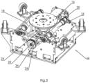
- the coupling element 22 preferably has at least one molding 44 and the coupling element 20 has at least one recess 46 Fig. 6 to 9 which interlock positively when engaged.
- the coupling elements 20, 22 can mesh with one another in a form-fitting and/or force-fitting manner.
- other shapes of the coupling elements 20, 22 are also conceivable, as long as they mesh with one another in a positive and/or non-positive manner.
- the alignment of the formation 44 and the recess 46 in the coupling position runs essentially along the plane spanned by the pivoting movement of the pivoting device 30 and/or parallel thereto.
- the formation 44 runs in Fig. 5 essentially along the pivoting path of the pivoting device 30, the recess 46 of the coupling element 20 also running in this direction.
- the formation 44 lies in the recess 46 and the pivoting movement of the pivoting device 30 in one plane or the pivoting axis of the pivoting movement of the pivoting device 30 is at right angles to the orientation direction of the formation 44 and the recess 46.
- the coupling elements 20, 22 could tilt during the coupling process due to the pivot angle and thus be damaged.
- the pivoting device 30 is a lifting-pivoting device, preferably designed as a piston-cylinder unit, with the lifting movement in particular being set up and used to actuate the fixing device 38 on the turntable 16.
- the lifting-pivoting device 30 is first actuated, with the lifting movement preferably actuating the fixing device 38. If the fixing device is in the fixed state according to the third sensor, only then does the pivoting movement of the turntable 16 take place.
- the coupling element 22 if it is not in the coupling position, is first brought into the coupling position.
- the sensor 32 preferably detects the position of the coupling element 22 and preferably causes the position transmitter to align the coupling element 22 accordingly if the coupling element 22 is not in the corresponding position.
- the sensor 36 preferably detects the position of the coupling element 20 or the turntable 16. In the drum mode, however, the turntable 16 should already be in position since it has already been previously fixed with the fixing device 38.
- the fixing device 38 should also be locked. This is determined by the third sensor. If all coupling elements 20, 22 are in position and the third sensor signals that the fixing device is in the fixed state, the pivoting movement of the turntable 16 takes place by means of the lifting-pivoting device 30.
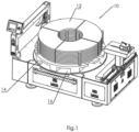
- the winding machine 10 is set up in at least one disengaged state for operation with a drum 28 rotating around a horizontal axis and in at least one engaged state is set up for operation with a pallet 14 rotating around a vertical axis.
- a drive device 48 which drives the turntable 16 in the engaged state via the shaft 34 and the gear 26. In the disengaged state, the drive device 48 drives the rollers 18 via the gear 26.
Landscapes
- Engineering & Computer Science (AREA)
- Mechanical Engineering (AREA)
- Tyre Moulding (AREA)
- Replacement Of Web Rolls (AREA)
- Basic Packing Technique (AREA)
Claims (15)
- Machine à enrouler (10) pour enrouler et/ou dérouler un matériau en bande ou en ruban (12) avec au moins un plateau tournant (16), lequel est disposé sur un bras pivotant (24) et peut être entraîné par au moins un dispositif d'entraînement (48) à l'aide d'au moins deux éléments de couplage opposés (20, 22), au moins un élément de couplage (20) étant associé au plateau tournant (16), ce plateau tournant (16) pouvant être amené entre au moins un état découplé et au moins un état couplé à l'aide d'un dispositif de pivotement (30),
caractérisée en ce que cette machine à enrouler présente au moins un premier détecteur et les éléments de couplage (20, 22) peuvent être positionnés avec le ou les premier(s) détecteur(s) dans une position de couplage de manière opposée l'un à l'autre pour la détection. - Machine à enrouler selon la revendication 1, caractérisée en ce qu'au moins un élément de couplage (20, 22) peut être fixé dans la position de couplage.
- Machine à enrouler selon la revendication 2, caractérisée en ce qu'au moins un dispositif de fixation (38) est prévu, lequel fixe l'élément de couplage (20) à l'état couplé dans la position de couplage.
- Machine à enrouler selon l'une des revendications précédentes, caractérisée en ce qu'au moins un deuxième détecteur (36) est prévu, lequel détecte la position de l'élément de couplage (20) et/ou avec lequel l'élément de couplage (20) peut être positionné dans la position de couplage.
- Machine à enrouler selon la revendication 3 ou 4, caractérisée en ce que le dispositif de fixation (38) est disposé sur ou dans le bras pivotant (24).
- Machine à enrouler selon l'une des revendications 3 à 5, caractérisée en ce que le dispositif de fixation (38) présente au moins une pièce de structure (40), laquelle coopère à l'état fixé avec au moins une contre-pièce (42) qui est associée au plateau tournant (16).
- Machine à enrouler selon l'une des revendications 3 à 6, caractérisée en ce qu'au moins un troisième détecteur est prévu, lequel détermine l'état du dispositif de fixation (38).
- Machine à enrouler selon l'une des revendications précédentes, caractérisée en ce qu'un élément de couplage (22) présente au moins une protubérance (44) et l'autre élément de couplage (20) présente au moins un évidement (46), ces protubérance (44) et évidement (46) s'assemblant avec complémentarité de forme à l'état couplé.
- Machine à enrouler selon la revendication 8, caractérisée en ce que l'alignement de la protubérance (44) et de l'évidement (46) dans la position de couplage s'étend pour l'essentiel le long du plan défini par le mouvement de pivotement du dispositif de pivotement (30) et/ou parallèlement à ce plan.
- Machine à enrouler selon l'une des revendications précédentes, caractérisée en ce que le dispositif de pivotement (30) est de préférence un dispositif de levage et de pivotement réalisé sous la forme d'une unité piston-cylindre, le déplacement de levage étant en particulier conçu pour actionner le dispositif de fixation (38) sur le plateau tournant (16).
- Machine à enrouler selon l'une des revendications précédentes, caractérisée en ce que le ou les dispositif(s) d'entraînement (48) entraîne(nt) à l'état découplé un tambour (28) tournant autour d'un axe horizontal ainsi qu'à l'état couplé une palette (14) tournant autour d'un axe vertical.
- Machine à enrouler selon l'une des revendications précédentes, caractérisée en ce qu'elle est conçue dans au moins un état découplé pour un fonctionnement avec un tambour (28) tournant autour d'un axe horizontal et en ce qu'elle est conçue dans au moins un état couplé pour un fonctionnement avec une palette (14) tournant autour d'un axe vertical.
- Procédé pour la transformation d'un plateau tournant (16) d'une machine à enrouler (10) selon la revendication 1 entre au moins un état couplé et au moins un état découplé, caractérisé par les étapes suivantes de :- positionnement pour la détection d'au moins un élément de couplage (20, 22) d'au moins deux éléments de couplage (20, 22) opposés l'un à l'autre dans une position de couplage,- pivotement du plateau tournant (16).
- Procédé selon la revendication 13, caractérisé par l'étape supplémentaire de- fixation d'au moins un élément de couplage (20, 22).
- Procédé selon la revendication 13 ou 14, caractérisé par l'état supplémentaire de :- détermination de l'état du dispositif de fixation (38).
Applications Claiming Priority (2)
| Application Number | Priority Date | Filing Date | Title |
|---|---|---|---|
| DE102020119382.3A DE102020119382A1 (de) | 2020-07-22 | 2020-07-22 | Wickelmaschine |
| PCT/EP2021/070354 WO2022018125A1 (fr) | 2020-07-22 | 2021-07-21 | Machine à enrouler |
Publications (3)
| Publication Number | Publication Date |
|---|---|
| EP4010132A1 EP4010132A1 (fr) | 2022-06-15 |
| EP4010132B1 true EP4010132B1 (fr) | 2023-12-27 |
| EP4010132C0 EP4010132C0 (fr) | 2023-12-27 |
Family
ID=77104084
Family Applications (1)
| Application Number | Title | Priority Date | Filing Date |
|---|---|---|---|
| EP21746744.8A Active EP4010132B1 (fr) | 2020-07-22 | 2021-07-21 | Machine à enrouler |
Country Status (6)
| Country | Link |
|---|---|
| US (1) | US20230294152A1 (fr) |
| EP (1) | EP4010132B1 (fr) |
| DE (1) | DE102020119382A1 (fr) |
| ES (1) | ES2974922T3 (fr) |
| PL (1) | PL4010132T3 (fr) |
| WO (1) | WO2022018125A1 (fr) |
Family Cites Families (13)
| Publication number | Priority date | Publication date | Assignee | Title |
|---|---|---|---|---|
| US2353651A (en) * | 1940-09-27 | 1944-07-18 | Aluminum Co Of America | Material handling mechanism |
| US3012683A (en) * | 1958-08-25 | 1961-12-12 | Sharon Steel Corp | Coil turner |
| US4249705A (en) * | 1979-11-07 | 1981-02-10 | Reel-O-Matic Systems, Incorporated | Method and apparatus for dispensing flexible coiled materials from pallets |
| US4582271A (en) * | 1982-12-28 | 1986-04-15 | Kentaro Takahashi | Continuous delivery apparatus for work material |
| US4720054A (en) * | 1985-12-05 | 1988-01-19 | Kent Corporation | System for supplying strip to a processing line |
| US4848694A (en) * | 1988-07-15 | 1989-07-18 | Joseph Julian | Strip decoiler |
| US4979692A (en) * | 1990-03-26 | 1990-12-25 | Joseph Julian | Convertible pallet coil and reel decoiler |
| US5123607A (en) * | 1990-07-06 | 1992-06-23 | Jones Johnnie L | Automatic wire dispenser |
| US6119971A (en) * | 1998-12-03 | 2000-09-19 | Accra-Wire Controls Inc. | Rotating arm decoiler with variable tension control |
| DE20203489U1 (de) | 2002-03-05 | 2002-06-27 | Harwi GmbH, Schweiß- und Automatisierungstechnik, 75179 Pforzheim | Horizontalabwickler zum Abwickeln von bandförmigen Material |
| DE102007048404A1 (de) * | 2007-10-09 | 2009-04-23 | Huras Automation Gmbh | Höhenverstellbares Element |
| DE202013105820U1 (de) * | 2013-12-19 | 2014-01-20 | Dietze & Schell Maschinenfabrik Gmbh & Co. Kg | Spulsystem mit zumindest einer Spulvorrichtung |
| DE102014111706A1 (de) * | 2014-08-15 | 2016-02-18 | Dietze & Schell Maschinenfabrik Gmbh & Co. Kg | Spulvorrichtung zum Spulen eines Wickelguts und Verfahren zum Betrieb einer Spulvorrichtung zum Spulen eines Wickelguts |
-
2020
- 2020-07-22 DE DE102020119382.3A patent/DE102020119382A1/de not_active Withdrawn
-
2021
- 2021-07-21 PL PL21746744.8T patent/PL4010132T3/pl unknown
- 2021-07-21 ES ES21746744T patent/ES2974922T3/es active Active
- 2021-07-21 EP EP21746744.8A patent/EP4010132B1/fr active Active
- 2021-07-21 WO PCT/EP2021/070354 patent/WO2022018125A1/fr not_active Ceased
- 2021-07-21 US US18/017,238 patent/US20230294152A1/en active Pending
Also Published As
| Publication number | Publication date |
|---|---|
| EP4010132A1 (fr) | 2022-06-15 |
| ES2974922T3 (es) | 2024-07-02 |
| DE102020119382A1 (de) | 2022-01-27 |
| PL4010132T3 (pl) | 2024-07-08 |
| EP4010132C0 (fr) | 2023-12-27 |
| US20230294152A1 (en) | 2023-09-21 |
| WO2022018125A1 (fr) | 2022-01-27 |
Similar Documents
| Publication | Publication Date | Title |
|---|---|---|
| DE112017000159B4 (de) | Vollautomatische Magnetring-Wickelmaschine | |
| DE112012003328B4 (de) | Randaustauschvorrichtung in einer Reifenunwuchtmessvorrichtung | |
| DE19831578B4 (de) | Positioniergerät und Positionierverfahren | |
| EP3766814B1 (fr) | Dispositif d'acheminement de câble, système d'usinage de câble et procédé d'acheminement d'un câble dans une machine d'usinage de câble | |
| EP3501995B1 (fr) | Procédé de commande des paramètres d'un système de banderolage | |
| DE68919527T2 (de) | Verfahren zum Aufwickeln eines Film auf eine Spule und zum Laden der Spule mit dem Film in ein Magazin sowie eine Vorrichtung zur Durchführung dieses Verfahrens. | |
| DE19525115B4 (de) | Vorrichtung zum Transportieren von Werkstücken | |
| DE69711934T2 (de) | Schneidmaschine mit automatischer positionsvorrichtung | |
| WO2016066581A1 (fr) | Procédé et dispositif de manipulation d'un matériau plat et/ou en feuille enroulé sur des rouleaux | |
| CH656823A5 (de) | Verfahren und vorrichtung zum positionieren von werkzeugen. | |
| DE3604504C2 (fr) | ||
| EP4010132B1 (fr) | Machine à enrouler | |
| EP0101025A2 (fr) | Dispositif de retournement dans une ligne de transport entre deux machines d'usinage | |
| DE60213294T2 (de) | Abwickelvorrichtung für rollen von bahnmaterial mit doppeltem antriebsmechanismus und entsprechendes abwickelverfahren | |
| DE102007028088A1 (de) | Vorrichtung zum Ändern der Transportrichtung von Stückgut | |
| EP1509468B1 (fr) | Element d'entrainement | |
| DE69616033T2 (de) | Paletten für Werkstücke mit manueller Einstellung der Auflager auf der Palette | |
| DE69813747T2 (de) | Einrichtung zum Zuführen von Schachtelzuschnitten und Verfahren | |
| DE102008061356B4 (de) | Bandeinfädelsystem sowie Verfahren zum Einführen eines Streifens | |
| DE69905925T2 (de) | Wickelanlage für walzgut | |
| DE4422288B4 (de) | Rollenpositionsregler für eine Endlosbandpresse | |
| EP2426055B1 (fr) | Procédé et dispositif de liaison pour anneaux de bandes refendues | |
| DE10224839B4 (de) | Spanndorn | |
| DE60211956T2 (de) | Verfahren und vorrichtung für den reifenaufbau | |
| EP3802385B1 (fr) | Dispositif de transport |
Legal Events
| Date | Code | Title | Description |
|---|---|---|---|
| STAA | Information on the status of an ep patent application or granted ep patent |
Free format text: STATUS: UNKNOWN |
|
| STAA | Information on the status of an ep patent application or granted ep patent |
Free format text: STATUS: THE INTERNATIONAL PUBLICATION HAS BEEN MADE |
|
| PUAI | Public reference made under article 153(3) epc to a published international application that has entered the european phase |
Free format text: ORIGINAL CODE: 0009012 |
|
| STAA | Information on the status of an ep patent application or granted ep patent |
Free format text: STATUS: REQUEST FOR EXAMINATION WAS MADE |
|
| 17P | Request for examination filed |
Effective date: 20220311 |
|
| AK | Designated contracting states |
Kind code of ref document: A1 Designated state(s): AL AT BE BG CH CY CZ DE DK EE ES FI FR GB GR HR HU IE IS IT LI LT LU LV MC MK MT NL NO PL PT RO RS SE SI SK SM TR |
|
| GRAP | Despatch of communication of intention to grant a patent |
Free format text: ORIGINAL CODE: EPIDOSNIGR1 |
|
| STAA | Information on the status of an ep patent application or granted ep patent |
Free format text: STATUS: GRANT OF PATENT IS INTENDED |
|
| INTG | Intention to grant announced |
Effective date: 20230726 |
|
| DAV | Request for validation of the european patent (deleted) | ||
| DAX | Request for extension of the european patent (deleted) | ||
| GRAS | Grant fee paid |
Free format text: ORIGINAL CODE: EPIDOSNIGR3 |
|
| GRAA | (expected) grant |
Free format text: ORIGINAL CODE: 0009210 |
|
| STAA | Information on the status of an ep patent application or granted ep patent |
Free format text: STATUS: THE PATENT HAS BEEN GRANTED |
|
| AK | Designated contracting states |
Kind code of ref document: B1 Designated state(s): AL AT BE BG CH CY CZ DE DK EE ES FI FR GB GR HR HU IE IS IT LI LT LU LV MC MK MT NL NO PL PT RO RS SE SI SK SM TR |
|
| REG | Reference to a national code |
Ref country code: GB Ref legal event code: FG4D Free format text: NOT ENGLISH |
|
| REG | Reference to a national code |
Ref country code: CH Ref legal event code: EP |
|
| REG | Reference to a national code |
Ref country code: DE Ref legal event code: R096 Ref document number: 502021002305 Country of ref document: DE |
|
| REG | Reference to a national code |
Ref country code: IE Ref legal event code: FG4D Free format text: LANGUAGE OF EP DOCUMENT: GERMAN |
|
| U01 | Request for unitary effect filed |
Effective date: 20240114 |
|
| U07 | Unitary effect registered |
Designated state(s): AT BE BG DE DK EE FI FR IT LT LU LV MT NL PT SE SI Effective date: 20240124 |
|
| PG25 | Lapsed in a contracting state [announced via postgrant information from national office to epo] |
Ref country code: GR Free format text: LAPSE BECAUSE OF FAILURE TO SUBMIT A TRANSLATION OF THE DESCRIPTION OR TO PAY THE FEE WITHIN THE PRESCRIBED TIME-LIMIT Effective date: 20240328 |
|
| PG25 | Lapsed in a contracting state [announced via postgrant information from national office to epo] |
Ref country code: GR Free format text: LAPSE BECAUSE OF FAILURE TO SUBMIT A TRANSLATION OF THE DESCRIPTION OR TO PAY THE FEE WITHIN THE PRESCRIBED TIME-LIMIT Effective date: 20240328 |
|
| PG25 | Lapsed in a contracting state [announced via postgrant information from national office to epo] |
Ref country code: RS Free format text: LAPSE BECAUSE OF FAILURE TO SUBMIT A TRANSLATION OF THE DESCRIPTION OR TO PAY THE FEE WITHIN THE PRESCRIBED TIME-LIMIT Effective date: 20231227 Ref country code: NO Free format text: LAPSE BECAUSE OF FAILURE TO SUBMIT A TRANSLATION OF THE DESCRIPTION OR TO PAY THE FEE WITHIN THE PRESCRIBED TIME-LIMIT Effective date: 20240327 Ref country code: HR Free format text: LAPSE BECAUSE OF FAILURE TO SUBMIT A TRANSLATION OF THE DESCRIPTION OR TO PAY THE FEE WITHIN THE PRESCRIBED TIME-LIMIT Effective date: 20231227 |
|
| PG25 | Lapsed in a contracting state [announced via postgrant information from national office to epo] |
Ref country code: IS Free format text: LAPSE BECAUSE OF FAILURE TO SUBMIT A TRANSLATION OF THE DESCRIPTION OR TO PAY THE FEE WITHIN THE PRESCRIBED TIME-LIMIT Effective date: 20240427 |
|
| REG | Reference to a national code |
Ref country code: ES Ref legal event code: FG2A Ref document number: 2974922 Country of ref document: ES Kind code of ref document: T3 Effective date: 20240702 |
|
| PG25 | Lapsed in a contracting state [announced via postgrant information from national office to epo] |
Ref country code: CZ Free format text: LAPSE BECAUSE OF FAILURE TO SUBMIT A TRANSLATION OF THE DESCRIPTION OR TO PAY THE FEE WITHIN THE PRESCRIBED TIME-LIMIT Effective date: 20231227 |
|
| PG25 | Lapsed in a contracting state [announced via postgrant information from national office to epo] |
Ref country code: SK Free format text: LAPSE BECAUSE OF FAILURE TO SUBMIT A TRANSLATION OF THE DESCRIPTION OR TO PAY THE FEE WITHIN THE PRESCRIBED TIME-LIMIT Effective date: 20231227 |
|
| PG25 | Lapsed in a contracting state [announced via postgrant information from national office to epo] |
Ref country code: SM Free format text: LAPSE BECAUSE OF FAILURE TO SUBMIT A TRANSLATION OF THE DESCRIPTION OR TO PAY THE FEE WITHIN THE PRESCRIBED TIME-LIMIT Effective date: 20231227 Ref country code: SK Free format text: LAPSE BECAUSE OF FAILURE TO SUBMIT A TRANSLATION OF THE DESCRIPTION OR TO PAY THE FEE WITHIN THE PRESCRIBED TIME-LIMIT Effective date: 20231227 Ref country code: RO Free format text: LAPSE BECAUSE OF FAILURE TO SUBMIT A TRANSLATION OF THE DESCRIPTION OR TO PAY THE FEE WITHIN THE PRESCRIBED TIME-LIMIT Effective date: 20231227 Ref country code: IS Free format text: LAPSE BECAUSE OF FAILURE TO SUBMIT A TRANSLATION OF THE DESCRIPTION OR TO PAY THE FEE WITHIN THE PRESCRIBED TIME-LIMIT Effective date: 20240427 Ref country code: CZ Free format text: LAPSE BECAUSE OF FAILURE TO SUBMIT A TRANSLATION OF THE DESCRIPTION OR TO PAY THE FEE WITHIN THE PRESCRIBED TIME-LIMIT Effective date: 20231227 |
|
| U20 | Renewal fee for the european patent with unitary effect paid |
Year of fee payment: 4 Effective date: 20240711 |
|
| REG | Reference to a national code |
Ref country code: DE Ref legal event code: R097 Ref document number: 502021002305 Country of ref document: DE |
|
| PLBE | No opposition filed within time limit |
Free format text: ORIGINAL CODE: 0009261 |
|
| STAA | Information on the status of an ep patent application or granted ep patent |
Free format text: STATUS: NO OPPOSITION FILED WITHIN TIME LIMIT |
|
| 26N | No opposition filed |
Effective date: 20240930 |
|
| PG25 | Lapsed in a contracting state [announced via postgrant information from national office to epo] |
Ref country code: MC Free format text: LAPSE BECAUSE OF FAILURE TO SUBMIT A TRANSLATION OF THE DESCRIPTION OR TO PAY THE FEE WITHIN THE PRESCRIBED TIME-LIMIT Effective date: 20231227 |
|
| PG25 | Lapsed in a contracting state [announced via postgrant information from national office to epo] |
Ref country code: IE Free format text: LAPSE BECAUSE OF NON-PAYMENT OF DUE FEES Effective date: 20240721 |
|
| U20 | Renewal fee for the european patent with unitary effect paid |
Year of fee payment: 5 Effective date: 20250709 |
|
| PGFP | Annual fee paid to national office [announced via postgrant information from national office to epo] |
Ref country code: ES Payment date: 20250819 Year of fee payment: 5 |
|
| PGFP | Annual fee paid to national office [announced via postgrant information from national office to epo] |
Ref country code: PL Payment date: 20250708 Year of fee payment: 5 |
|
| PGFP | Annual fee paid to national office [announced via postgrant information from national office to epo] |
Ref country code: CH Payment date: 20250801 Year of fee payment: 5 |
|
| PG25 | Lapsed in a contracting state [announced via postgrant information from national office to epo] |
Ref country code: CY Free format text: LAPSE BECAUSE OF FAILURE TO SUBMIT A TRANSLATION OF THE DESCRIPTION OR TO PAY THE FEE WITHIN THE PRESCRIBED TIME-LIMIT; INVALID AB INITIO Effective date: 20210721 |
|
| PG25 | Lapsed in a contracting state [announced via postgrant information from national office to epo] |
Ref country code: HU Free format text: LAPSE BECAUSE OF FAILURE TO SUBMIT A TRANSLATION OF THE DESCRIPTION OR TO PAY THE FEE WITHIN THE PRESCRIBED TIME-LIMIT; INVALID AB INITIO Effective date: 20210721 |
|
| GBPC | Gb: european patent ceased through non-payment of renewal fee |
Effective date: 20250721 |
|
| PG25 | Lapsed in a contracting state [announced via postgrant information from national office to epo] |
Ref country code: GB Free format text: LAPSE BECAUSE OF NON-PAYMENT OF DUE FEES Effective date: 20250721 |