EP4010607B1 - Bande de freinage d'un disque pour frein à disque de type ventilé - Google Patents
Bande de freinage d'un disque pour frein à disque de type ventilé Download PDFInfo
- Publication number
- EP4010607B1 EP4010607B1 EP20754028.7A EP20754028A EP4010607B1 EP 4010607 B1 EP4010607 B1 EP 4010607B1 EP 20754028 A EP20754028 A EP 20754028A EP 4010607 B1 EP4010607 B1 EP 4010607B1
- Authority
- EP
- European Patent Office
- Prior art keywords
- shaped pin
- shaped
- braking band
- braking
- pins
- Prior art date
- Legal status (The legal status is an assumption and is not a legal conclusion. Google has not performed a legal analysis and makes no representation as to the accuracy of the status listed.)
- Active
Links
Images



Classifications
-
- F—MECHANICAL ENGINEERING; LIGHTING; HEATING; WEAPONS; BLASTING
- F16—ENGINEERING ELEMENTS AND UNITS; GENERAL MEASURES FOR PRODUCING AND MAINTAINING EFFECTIVE FUNCTIONING OF MACHINES OR INSTALLATIONS; THERMAL INSULATION IN GENERAL
- F16D—COUPLINGS FOR TRANSMITTING ROTATION; CLUTCHES; BRAKES
- F16D65/00—Parts or details
- F16D65/02—Braking members; Mounting thereof
- F16D65/12—Discs; Drums for disc brakes
- F16D65/128—Discs; Drums for disc brakes characterised by means for cooling
-
- F—MECHANICAL ENGINEERING; LIGHTING; HEATING; WEAPONS; BLASTING
- F16—ENGINEERING ELEMENTS AND UNITS; GENERAL MEASURES FOR PRODUCING AND MAINTAINING EFFECTIVE FUNCTIONING OF MACHINES OR INSTALLATIONS; THERMAL INSULATION IN GENERAL
- F16D—COUPLINGS FOR TRANSMITTING ROTATION; CLUTCHES; BRAKES
- F16D65/00—Parts or details
- F16D65/78—Features relating to cooling
- F16D65/84—Features relating to cooling for disc brakes
- F16D65/847—Features relating to cooling for disc brakes with open cooling system, e.g. cooled by air
-
- F—MECHANICAL ENGINEERING; LIGHTING; HEATING; WEAPONS; BLASTING
- F16—ENGINEERING ELEMENTS AND UNITS; GENERAL MEASURES FOR PRODUCING AND MAINTAINING EFFECTIVE FUNCTIONING OF MACHINES OR INSTALLATIONS; THERMAL INSULATION IN GENERAL
- F16D—COUPLINGS FOR TRANSMITTING ROTATION; CLUTCHES; BRAKES
- F16D65/00—Parts or details
- F16D65/02—Braking members; Mounting thereof
- F16D2065/13—Parts or details of discs or drums
- F16D2065/1304—Structure
- F16D2065/1308—Structure one-part
-
- F—MECHANICAL ENGINEERING; LIGHTING; HEATING; WEAPONS; BLASTING
- F16—ENGINEERING ELEMENTS AND UNITS; GENERAL MEASURES FOR PRODUCING AND MAINTAINING EFFECTIVE FUNCTIONING OF MACHINES OR INSTALLATIONS; THERMAL INSULATION IN GENERAL
- F16D—COUPLINGS FOR TRANSMITTING ROTATION; CLUTCHES; BRAKES
- F16D65/00—Parts or details
- F16D65/02—Braking members; Mounting thereof
- F16D2065/13—Parts or details of discs or drums
- F16D2065/1304—Structure
- F16D2065/1328—Structure internal cavities, e.g. cooling channels
-
- F—MECHANICAL ENGINEERING; LIGHTING; HEATING; WEAPONS; BLASTING
- F16—ENGINEERING ELEMENTS AND UNITS; GENERAL MEASURES FOR PRODUCING AND MAINTAINING EFFECTIVE FUNCTIONING OF MACHINES OR INSTALLATIONS; THERMAL INSULATION IN GENERAL
- F16D—COUPLINGS FOR TRANSMITTING ROTATION; CLUTCHES; BRAKES
- F16D65/00—Parts or details
- F16D65/02—Braking members; Mounting thereof
- F16D2065/13—Parts or details of discs or drums
- F16D2065/134—Connection
- F16D2065/1344—Connection permanent, e.g. by casting
-
- F—MECHANICAL ENGINEERING; LIGHTING; HEATING; WEAPONS; BLASTING
- F16—ENGINEERING ELEMENTS AND UNITS; GENERAL MEASURES FOR PRODUCING AND MAINTAINING EFFECTIVE FUNCTIONING OF MACHINES OR INSTALLATIONS; THERMAL INSULATION IN GENERAL
- F16D—COUPLINGS FOR TRANSMITTING ROTATION; CLUTCHES; BRAKES
- F16D65/00—Parts or details
- F16D65/78—Features relating to cooling
- F16D2065/788—Internal cooling channels
Definitions
- the present invention relates to a braking band and to a ventilated disc for disc brake, particularly, but not exclusively, for applications in the automobile field, as well as to a vehicle having said ventilated disc.
- the brake caliper in a disc brake is generally arranged straddling the peripheral outer margin of a brake disc, adapted to rotate about a rotation axis (A-A) defining an axial direction (X-X).
- a radial direction (R-R) is also defined in a disc brake, which radial direction substantially is orthogonal to said axial direction (X-X), and a circumferential direction (C-C), which is orthogonal both to said axial direction (X-X) and to said radial direction (R-R), as well as a tangential direction (T-T) which is locally, or better punctually orthogonal, both to said axial direction (X-X) and to said radial direction (R-R).
- the discs for disc brake comprise a bell adapted to associate the disc with a hub of a vehicle, from which an annular portion extends, called braking band, intended to cooperate with brake pads of a caliper.
- the braking band consists of two plates facing and connected to each other, respectively, by means of connecting elements, for example in the form of pins or fins.
- the outer surfaces of the two plates define opposite braking surfaces, while the inner surfaces delimit, jointly with the pins or the fins, ventilation channels for cooling the disc, channels in which air flows according to a centrifugal direction during the rotating motion of the disc itself.
- Said braking band is intended to cooperate with calipers for disc brake adapted to exert a braking action on the vehicle, thus exerting, by means of the aforesaid pads, friction on the opposite surfaces of the two plates, said braking surfaces.
- the heat generated indeed causes the occurrence of several undesired phenomena, such as the deformation of the braking band, the formation of cracks on the braking surfaces or localized transformations of state of the material forming the braking band which in turn result in the deterioration of the braking band itself.
- Ventilated discs of the aforementioned type have undergone a continuous evolution over time, in particular concerning the number and shape of the so-called ventilation channels, thus defining the gap formed by the two mutually axially facing plates.
- the so-called “pin” discs have shown to be particularly efficient in terms of heat dissipation, i.e. cooling, in which ventilation channels are internally limited by particular pillar connecting elements having limited or substantially little deformed radial and circumferential extension with respect to the axial extension thereof, defined as “pins”, which transversely connect the two plates.
- pin ventilated discs are known from EP 1 373 751 B1 , in which the pins are geometrically arranged along three concentric circumferences, which are coaxial to the disc and having different radius, to form three “ranks”; if sectioned on a plane parallel to the two plates and which is median with respect thereto, the pins have sections of various type (for example, pins with “rhomboidal” sections in the intermediate and inner ranks; "drop-shaped" pins in the outer rank).
- the known ventilated discs include the so-called “fins” or “tabs” discs, in which the ventilation channels are internally limited by particular connecting elements elongated along a main direction, for example directed according to a direction parallel to the radial direction (R-R), or spiral, and which transversely connect the two plates.
- the need on the one hand is therefore particularly felt in the field to increase the efficiency of the dispersion of the heat generated by the braking so as to contain the temperatures reached by the disc during and following the braking, and on the other hand, the need to increase the mechanical resistance of these central portions of the braking band.
- ventilated discs of the mentioned type do not provide per se a solution to a further problem which occurs simultaneously with the above-mentioned problems and which is to be solved at the same time, which problem may affect the disc brakes, in particular the disc brakes with ventilated discs, the problem being briefly disclosed hereinbelow.
- the disc and the braking bands may mechanically vibrate at various frequencies correlated with the various vibration modes of the disc itself.
- Such vibrations of the disc may result, for example from resonances triggered by vibrations of objects mechanically coupled to the disc which are stressed in braking step should the vibration frequencies of such objects coincide with or be sufficiently close to the vibration frequencies of the disc.
- IT 1 273 754 has braking bands with protrusions projecting into the inner part of the plates, towards the gap between the two plates, in particular positions and with masses specifically identified in order to reduce the vibrations which occur and the subsequent noise.
- the need remains strongly felt to keep a distance between shaped pins and connecting elements, especially close to the outer edge of the disc, for example to simplify the production process of the core which allows making the braking band by founding: since the geometry of the pins is achieved due to the core which geometrically represents the spaces between one pin and the other, it is required to ensure minimum sections so the sand for the cores is capable of filling all the spaces which form the gap and furthermore, said core has minimum sections capable of providing a structural resistance of the core itself which is sufficient for the handling thereof and the melting of the braking band.
- the contrasting need is strongly felt to avoid a broad annular area of the gap which is empty of connecting elements or protrusions, thus avoiding a poor distribution of the temperature on the braking band such as to generate a vibration of the disc or other out-of-balance phenomenon.
- the problem at the basis of the present invention is that of devising a braking band and a disc for disc brake which have structural and functional features such as to meet the aforesaid needs while obviating the drawbacks mentioned with reference to the known art.
- the present invention aims to provide a braking device in which the tendency to create these vibratory waves and subsequent whistling is reduced.
- the solution suggested maintains a very high, and in certain embodiments even improved, disc cooling efficiency, for example the efficiency is strongly improved due to the increased turbulence of the flow of air flowing through the gap of the braking band, a turbulence caused by the specific shape of the shaped pins between and the plates and arranged between the connecting elements and extending in circumferential direction.
- the solutions suggested allow the mass of the braking band arranged close to the outer edge thereof to be increased in order to reduce the vibrating methods of the braking band of the "out of plane” type which affect the performance of the brake quite negatively if excited.
- a distance may be ensured between the shaped pins and the connecting elements, especially close to the outer edge of the disc, thus simplifying the production process.
- a minimum distance to be ensured between the connecting elements and the shaped pins (variable from 5 mm to 7 mm, typically 6 mm) for the convenient feasibility of the founding core with which the braking band is made: since the geometry of the connecting elements is achieved due to the core which geometrically represents the spaces between one connecting element and the other, it is required to ensure minimum sections in order for the foundry sand to be capable of filling all the spaces, as well as to ensure the structural resistance of the core itself.
- the mass close to the outer edge may be increased while avoiding an excessive occlusion or narrowing of the ventilation channel, while structurally strengthening the band to limit the formation and propagation of cracks.
- shaped pins capable of further increasing the available surface for the heat exchange may be ensured due to the solutions suggested.
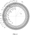
- a braking band 1 of a disc for disc brake 2 of ventilated type is provided.
- Said braking band 1 extends between an inner diameter D1, close to a rotation axis X-X of the braking band 1, and an outer diameter D2, far from said rotation axis X-X.
- Said rotation axis defines an axial direction X-X.
- Said braking band 1 defines a radial direction R-R, substantially orthogonal to said axial direction X-X, and a circumferential direction C-C, orthogonal both to said axial direction X-X and to said radial direction R-R.
- Said braking band 1 comprises two mutually facing plates 3, 4.
- Said plates 3, 4 comprise inner surfaces 5, 6, either directly or indirectly mutually facing and delimiting a gap 7 which defines a ventilation duct for the braking band 1.
- Said plates 3, 4 comprise outer surfaces 8, 9.
- Said outer surfaces 8, 9 comprise flat and mutually opposite circumferential portions which form braking surfaces 10, 11.
- portions of the outer surfaces 8, 9 cooperate with brake pads received in a brake caliper to exert a braking action when sandwiched against the braking band 1.
- the portion of the outer surfaces 8, 9 which is brushed or involved by the pads defines the braking surfaces 10, 11.
- Said plates 3, 4 comprise a plate body 12, 13 having an extension in axial direction X-X or plate thickness 14, 15.
- each plate 3, 4 shows a plate thickness 14,15 which is given by the thickness in axial direction of the plate body 12 of plate 3, 4.
- Said plates 3, 4 are joined to each other by heat dissipating elements or connecting elements 16, 17, 18 of the plates 3, 4.
- Said connecting elements 16, 17, 18 are shaped as columns and/or ribs which project from a plate towards the opposite plate in the form of bridges which connect the plates 3, 4.
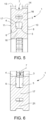
- At least one of the plates 3; 4 comprises at least one shaped pin 20, 21 which projects from said plate 3; 4 into said gap 7, thus reaching the opposite plate 4; 3.
- Said shaped pin 20, 21 forms at least one localized narrowing of said gap 7. In other words, travelling said gap 7, a reduction of the section in axial direction X-X of the width of gap 7 is detected when said shaped pin 20, 21 is reached.
- Said shaped pin 20, 21 forms at least one thickening of the plate body 12; 13, thus creating a localized increase of said plate thickness 14; 15.
- thickness 14 increases at said shaped pin 20, 21.
- a braking band 1 of a disc for disc brake 2 of ventilated type extends between an inner diameter D1, close to a rotation axis X-X of the braking band 1, and an outer diameter D2, far from said rotation axis X-X, said rotation axis defining an axial direction X-X.
- Said braking band 1 defines a radial direction R-R, substantially orthogonal to said axial direction X-X, and a circumferential direction C-C, orthogonal both to said axial direction X-X and to said radial direction R-R, and a tangential direction T-T, punctually orthogonal to an axial direction X-X and a radial direction R-R.
- Said braking band 1 comprises two mutually facing plates 3, 4.
- Said plates 3, 4 comprise inner surfaces 5, 6, either directly or indirectly facing and delimiting a gap 7.
- Said plates 3, 4 comprise a plate body 12, 13 having a predetermined extension in axial direction X-X or predetermined plate thickness 14, 15.
- Said connecting elements 16, 17, 18 are shaped as columns and/or ribs and/or fins which project from a plate towards the opposite plate, thus forming bridges which connect the plates 3, 4 to each other.
- At least one of the plates 3, 4 comprises at least one shaped pin 20, 21 which projects from said plate 3, 4 into said gap 7 reaching the opposite plate 4, 3, thus forming at least one localized narrowing of said gap 7 and a thickening of the plate body 12, 13, thus creating a localized increase of said plate thickness 14, 15.
- Said at least one shaped pin 20, 21 remains separated from each connecting element 16, 17, 18, in which the thickness of the at least one plate 3, 4 about said at least one shaped pin 20, 21 is substantially equal to said predetermined plate thickness 14, 15.
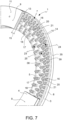
- Said at least one shaped pin 20 advantageously extends forming at least two separate shaped pin branches 31, 32.
- the thickness of the at least one plate 3, 4 between said at least two shaped pin branches 31, 32 is substantially equal to said predetermined plate thickness 14, 15.
- said inner surfaces 5, 6 are flat surfaces.
- said plates 3, 4, comprise outer surfaces 8, 9.
- Said outer surfaces 8, 9 comprise flat and opposite annular portions which form braking surfaces 10, 11.
- the distance between said inner surfaces 5, 6 and said braking surfaces 10, 11 defines said predetermined plate thickness 14, 15.
- the maximum axial width or axial extension of said gap 7 is reached between said at least one shaped pin 20, 21 and each adjacent connecting element.
- said at least one shaped pin 20 and its at least two separate shaped pin branches 31, 32 have a symmetrical shape with respect to a plane containing an axial direction X-X and a radial direction R-R.
- said braking band 1 has an outer band edge 35 at said outer band diameter D2.
- said at least one shaped pin 20 and its at least two separate branches 31, 32 form a branched shaped pin 34
- said branched shaped pin 34 displays a "V"-shaped section which forms a concavity facing the outer edge of the disc.
- said at least one shaped pin 20 and its at least two separate branches 31, 32 form a branched shaped pin 34, said branched shaped pin 34 is crescent-shaped.
- said at least one shaped pin 20 comprises a central shaped pin body 36 in the shape of a cylinder, from which said at least two separate shaped pin branches 31, 32 project.
- the extensions of said at least two shaped pin branches 31, 32 are arranged straddling at least one connecting element 16.
- said braking band 1 comprises at least one further shaped pin 21.
- the extension of at least one of said at least two branches 31, 32 intersects said at least one further shaped pin 21.
- said braking band 1 comprises at least two further shaped pins 21 arranged at the sides of a connecting element 16.
- the extension of said at least two branches 31, 32 each intersects at least one further shaped pin 21.
- said at least one further shaped pin 21 is drop-shaped.
- said at least one further shaped pin 21 has a further shaped pin - tapered extension 37 tapered in radial direction R-R, preferably directed towards said rotation axis X-X.
- said at least one further shaped pin 21 is a plurality of further shaped pins 21.
- said at least one further shaped pin 21 is a plurality of further shaped pins 21 arranged close to an outer band edge 35.
- said at least one further shaped pin 21 is a plurality of further shaped pins 21 evenly distributed along a circumference.
- said at least one further shaped pin 21 is a plurality of further shaped pins 21 arranged between a plurality of connecting elements 16.
- said at least one shaped pin 20 and its at least two separate shaped pin branches 31, 32 are a plurality of shaped pins 20, each with respective at least two separate shaped pin branches 31, 32.
- said at least one shaped pin 20 and its at least two separate shaped pin branches 31, 32 are a plurality of shaped pins 20 evenly distributed along a circumference.
- said at least one shaped pin 20 and its at least two separate shaped pin branches 31, 32 are a plurality of shaped pins 20 arranged at least in part between connecting elements 17.
- said at least one shaped pin 20 and its at least two separate branches 31, 32 form a branched shaped pin 34, said branched shaped pin 34 has a rounded outer shaped pin surface 38 connected to said inner surface 5 or 6 from which it projects into gap 7.
- said at least one further shaped pin 21 has a further shaped pin - rounded outer surface 39 connected to said inner surface 5 or 6 from which it projects into gap 7.
- said connecting elements 16, 17, 18 are grouped into at least two rows or ranks 23, 24, 25 arranged circumferentially.
- a first of said ranks 23 is arranged internally in a radial direction or towards said axis X-X close to said inner diameter D1.
- a second of said ranks 24 is radially located further from said axis X-X close to said outer diameter D2.
- At least one third of said ranks 24 is arranged radially between said first inner row 23 and said second outer row 24.
- each of said connecting elements 16 of said second of said rows 24 has three shaped pins or combination of shaped pins facing it on three sides, and further shaped pins 20, 21.
- said at least one shaped pin 20 or 21 is at least a plurality of shaped pins, each plurality of said shaped pins 20 or 21 is arranged between connecting elements 16 or 17 of the same rank 23, 24.
- At least some of said connecting elements 16, 17, 18 are fins or ribs which have, on a plane substantially parallel to the air flow along gap 7, an elongated shape section, e.g. in the radial direction R-R.
- said connecting elements 16 close to the outer band diameter D2 or outer rank 24 have an elongated drop-shaped section in radial direction R-R on a plane substantially parallel to the flow of air along gap 7.
- At least two of said connecting elements 17, 18 have, on a plane substantially parallel to the air flow along gap 7, a diamond- or rhombus-shaped section 27 with four vertices 28 joined by four sides 29 in which said sides delimiting said section substantially are rectilinear in shape.
- all the shaped pins 20, 21 of said shaped pins 20, 21 are arranged in a circular portion of said gap 7 close to said outer band diameter D2.
- all the shaped pins 20, 21 of said shaped pins 20, 21 are arranged in a circular portion of said gap 7 close to where an outer rank 24 of connecting elements 16 is present.
- the present invention likewise relates to a disc brake disc 2 comprising a braking band 1 according to any one of the above-described embodiments.
- the present invention likewise relates to a vehicle comprising a braking band 1 according to any one of the above-described embodiments.
- the assembly of shaped pins 20, 21 arranged close to one another forms a group of shaped pins 20, 21 which is arranged circumferentially, thus creating a circumferential distribution which has circumferential discontinuities concentrated close to the outer diameter D2 of the braking band and capable of creating an uneven distribution of the assembly of shaped pins, a distribution adapted to avoid the presence of vibrating modes of the braking band 1 which, when arranged to resonate, create annoying noises or whistling.
- a braking band 1 has an outer diameter D2 of 415 mm, an inner diameter of 295 mm and a thickness of 33 mm.
- Gap 7, or the ventilation channel has a height assessed in axial direction X-X of 12.6 mm.
- the two plates 3, 4 are connected to each other by connecting elements 16, 17, 18 in the form of columns arranged over three concentric rows or ranks 23, 24, 25 and said connecting elements 16, 17, 18 are arranged according to a staggered arrangement.
- the connecting elements in the outer rank 24 have a drop shape assessed on an average flow plane which travels gap 7, with tapered extension directed according to the radial direction R-R and facing the rotation axis X-X.
- the connecting elements 17, 18 in the intermediate rank 25 and inner rank 23 have a rhomboidal shape assessed on an average flow plane which travels gap 7.
- Each rank has 47 connecting elements 16 or 17 or 18.
- Further shaped pins 21 are present in the outer rank 23 between each connecting element 16. Said further shaped pins 21 have a drop shape on a plane containing a radial direction R-R and circumferential direction C-C, with tapered extension directed according to the radial direction R-R and facing the rotation axis X-X.
- Shaped pins 20 are present in the intermediate rank 25 between each connecting element 17. Said further shaped pins 20 have, on a plane containing a radial direction R-R and circumferential direction C-C, a branched shape 34, i.e. a cylindrical central body from which a first and a second shaped pin branch 31, 32 project separately from each other.
- Said shaped pin 20 has extension in axial direction of 3.4 mm.
- the base of said shaped pin 20 has a radius of 4 mm.
- the overall height of the shape of the shaped pin 20 is 9.7 mm and the overall width including the branches is 13.5 mm.
- the outer surface 38 of the shaped pin 20 is joined to the flat inner surface 5 or 6 with a radius of 2 mm.
Landscapes
- Engineering & Computer Science (AREA)
- General Engineering & Computer Science (AREA)
- Mechanical Engineering (AREA)
- Braking Arrangements (AREA)
Claims (15)
- Bande de freinage (1) d'un disque pour frein à disque (2) de type ventilé,- ladite bande de freinage (1) s'étendant entre un diamètre interne (D1), à proximité d'un axe de rotation (X-X) de la bande de freinage (1), et un diamètre externe (D2), éloigné dudit axe de rotation (X-X), ledit axe de rotation définissant une direction axiale (X-X) ;- ladite bande de freinage (1) définissant une direction radiale (R-R), sensiblement orthogonale à ladite direction axiale (X-X), et une direction circonférentielle (C-C), orthogonale à ladite direction axiale (X-X) et à ladite direction radiale (R-R), et une direction tangentielle (T-T) ponctuellement orthogonale à ladite direction axiale (X-X) et à une direction radiale (R-R) ;- ladite bande de freinage (1) comprenant deux plaques (3, 4) se faisant face mutuellement ;
lesdites plaques (3, 4) comprenant des surfaces internes (5, 6), faisant directement ou indirectement face à un espace (7) et délimitant celui-ci ;- lesdites plaques (3, 4) comprenant un corps de plaque (12, 13) ayant un prolongement prédéterminé dans une direction axiale (X-X) ou une épaisseur de plaque (14, 15) prédéterminée ;- lesdites plaques (3, 4) étant jointes entre elles par des éléments de dissipation thermique et de liaison (16, 17, 18), également appelés éléments de liaison ;- lesdits éléments de liaison (16, 17, 18) étant façonnés sous forme de colonnes et/ou nervures et/ou ailettes qui font saillie d'une plaque vers la plaque opposée, formant ainsi des ponts qui relient les plaques (3, 4) entre elles ; dans laquelle- dans laquelle l'une des plaques (3 ; 4) comprend au moins une broche façonnée (20, 21) qui fait saillie de ladite plaque (3 ; 4) dans ledit espace (7) atteignant la plaque opposée (4 ; 3), formant ainsi au moins un rétrécissement localisé dudit espace (7) et un épaississement du corps de plaque (12 ; 13), créant ainsi une augmentation localisée de ladite épaisseur de plaque (14 ; 15) ; et dans laquelle- ladite au moins une broche façonnée (20, 21) reste séparée de chaque élément de liaison (16, 17, 18), dans laquelle l'épaisseur d'au moins une plaque (3 ; 4) autour de ladite au moins une broche façonnée (20, 21) est sensiblement égale à ladite épaisseur de ladite plaque (14, 15) prédéterminée ;
dans laquelle- ladite au moins une broche façonnée (20) s'étend en formant au moins deux branches de broche façonnée (31, 32) séparées ;
caractérisée en ce que- les prolongements desdites au moins deux branches de broche façonnée (31, 32) sont disposées de manière à chevaucher au moins un élément de liaison (16). - Bande de freinage (1), selon la revendication 1, dans laquelle- l'épaisseur d'au moins une plaque (3 ; 4) entre lesdites au moins deux branches de broche façonnée (31, 32) est sensiblement égale à ladite épaisseur de plaque prédéfinie (14, 15) ; et dans laquelle
les surfaces internes (5, 6) sont des surfaces plates ; et dans laquelle- lesdites plaques (3, 4) comprenant des surfaces externes (8, 9) ; et dans laquelle- lesdites surfaces externes (8, 9) comprennent des portions annulaires plates et opposées qui forment des surfaces de freinage (10, 11) ; et dans laquelle
la distance entre lesdites surfaces internes (5, 6) et lesdites surfaces de freinage (10, 11) définit ladite épaisseur de plaque (14, 15) prédéterminée ; et/ou dans laquelle- la largeur axiale maximale ou le prolongement axial dudit espace (7) est atteint(e) entre ladite au moins une broche façonnée (20, 21) et chaque élément de liaison adjacent. - Bande de freinage (1), selon la revendication 1 ou 2, dans laquelle- ledit au moins une broche façonnée (20) et ses au moins deux branches de broche façonnée (31, 32) séparées ont une forme symétrique par rapport à un plan contenant une direction axiale (X-X) et une direction radiale (R-R) ; et/ou dans laquelle- ladite bande de freinage (1) a un bord externe (35) de bande au niveau dudit diamètre externe (D2) de bande ; et dans laquelle- lorsqu'elle est vue sur un plan comprenant une direction radiale (R-R) et une direction circonférentielle (C-C), ladite au moins une broche façonnée (20) et ses au moins deux branches de broche façonnée (31, 32) séparées forment une broche façonnée ramifiée (34), ladite broche façonnée ramifiée (34) présente une section en forme de « V » qui forme une concavité tournée vers le bord externe du disque ; et/ou dans laquelle- lorsqu'elle est vue sur un plan comprenant une direction radiale (R-R) et une direction circonférentielle (C-C), ladite au moins une broche façonnée (20) et ses au moins deux branches de broche façonnée (31, 32) séparées forment une broche façonnée ramifiée (34), ladite broche façonnée ramifiée (34) est en forme de croissant ; et/ou dans laquelle- ladite au moins une broche façonnée (20) comprend un corps central de broche façonnée en forme de cylindre (36) à partir duquel lesdites au moins deux branches de broche façonnée (31, 32) séparées font saillie.
- Bande de freinage (1), selon l'une quelconque des revendications précédentes, dans laquelle- ladite bande de freinage (1) comprend une broche façonnée supplémentaire (21) ; et dans laquelle- le prolongement d'au moins l'une desdites au moins deux branches de broche façonnée (31, 32) croise ladite au moins une broche façonnée supplémentaire (21).
- Bande de freinage (1) selon l'une quelconque des revendications précédentes, dans laquelle - ladite bande de freinage (1) comprend au moins deux broches façonnées supplémentaires (21) disposées sur les côtés d'un élément de liaison (16) ; et dans laquelle- le prolongement de chacune desdites au moins deux branches de broche façonne (31, 32) coupe au moins une broche façonnée supplémentaire (21) ; et/ou dans laquelle- lorsqu'elle est vue sur un plan comprenant une direction radiale (R-R) et une direction circonférentielle (C-C), ladite au moins une broche façonnée supplémentaire (21) est en forme de goutte ; et/ou dans laquelle- au moins une broche façonnée supplémentaire (21) a un prolongement conique de broche façonnée supplémentaire (37) conique dans la direction radiale (R-R), de préférence dirigé vers ledit axe de rotation (X-X).
- Bande de freinage (1) selon l'une quelconque des revendications précédentes, dans laquelle- ladite au moins une broche façonnée supplémentaire (21) est une pluralité de broches façonnées supplémentaires (21) ; et dans laquelle- ladite au moins une broche façonnée supplémentaire (21) est une pluralité de broches façonnées supplémentaires (21) disposées à proximité d'un bord externe (35) de bande ; et dans laquelle- ladite au moins une broche façonnée supplémentaire (21) est une pluralité de broches façonnées supplémentaires (21) uniformément réparties le long d'une circonférence ; et dans laquelle- au moins une broche façonnée supplémentaire (21) est une pluralité de broches façonnées supplémentaires (21) disposées entre une pluralité d'éléments de liaison (16).
- Bande de freinage (1), selon l'une quelconque des revendications précédentes, dans laquelle- ladite au moins une broche façonnée (20) et ses au moins deux branches de broche façonnée (31, 32) séparées sont une pluralité de broches façonnées (20), chacune ayant respectivement au moins deux branches de broche façonnée (31, 32) séparées ; et/ou dans laquelle- ladite au moins une broche façonnée (20) et ses au moins deux branches de broche façonnée (31, 32) séparées sont une pluralité de broches façonnées (20) uniformément réparties le long d'une circonférence ; et/ou dans laquelle- ladite au moins une broche façonnée (20) et ses au moins deux branches de broche façonnée (31, 32) séparées sont une pluralité de broches façonnées (20) disposées au moins en partie entre des éléments de liaison (17).
- Bande de freinage (1), selon l'une quelconque des revendications précédentes, dans laquelle - au moins une circonférence concentrique à l'axe de rotation (X-X) de la bande de freinage (1), qui est disposée sur lesdites surfaces internes (5, 6) et croise lesdits éléments de liaison (17) d'un rang interne ou intermédiaire, croise également ladite au moins une broche façonnée (20) ; et/ou dans laquelle- au moins une circonférence concentrique à l'axe de rotation (X-X) de la bande de freinage (1), qui est disposée sur lesdites surfaces internes (5, 6) et croise lesdits éléments de liaison (16) d'un rang externe, croise également ladite au moins une broche façonnée supplémentaire (21) ; et/ou dans laquelle- lorsqu'elle est vue sur un plan comprenant une direction radiale (R-R) et une direction circonférentielle (C-C), ladite au moins une broche façonnée (20) et ses au moins deux branches de broche façonnée (31, 32) séparées forment une broche façonnée ramifiée (34), ladite broche façonnée ramifiée (34) a une surface externe de broche façonnée arrondie (38) reliée à ladite surface interne (5 ou 6) à partir de laquelle elle fait saillie dans l'espace (7) ; et/ou dans laquelle- lorsqu'elle est vue sur un plan comprenant une direction radiale (R-R) et une direction circonférentielle (C-C), ladite au moins une broche façonnée supplémentaire (21) a une surface externe arrondie (39) de broche façonnée supplémentaire reliée à ladite surface interne (5 ou 6) à partir de laquelle elle fait saillie dans l'espace (7).
- Bande de freinage (1), selon l'une quelconque des revendications précédentes, dans laquelle- lesdits éléments de liaison (16, 17, 18) sont regroupés en au moins deux lignes ou rangées (23, 24, 25) disposés de manière circonférentielle ; et dans laquelle- une première desdites rangées (23) est disposée intérieurement dans une direction radiale ou vers ledit axe (X-X) à proximité dudit diamètre interne (D1) ; et dans laquelle- une deuxième desdites rangées (24) est située radialement plus loin dudit axe (X-X) à proximité dudit diamètre externe (D2) ; et/ou dans laquelle- au moins une troisième desdites rangées (24) est disposée radialement entre ladite première ligne interne (23) et ladite deuxième ligne externe (24).
- Bande de freinage (1), selon la revendication précédente, dans laquelle- chaque élément de liaison (16) de ladite deuxième desdites lignes (24) a trois broches façonnées ou une combinaison de broches façonnées lui faisant face sur trois côtés, et des broches façonnées supplémentaires (20, 21) ; et/ou dans laquelle- ladite au moins une broche façonnée (20 ou 21) est au moins une pluralité de broches façonnées, chaque pluralité desdites broches façonnées (20 ou 21) est disposée entre des éléments de liaison (16 ou 17) de même rang (23 ; 24).
- Bande de freinage (1), selon l'une quelconque des revendications précédentes, dans laquelle- au moins certains desdits éléments de liaison (16, 17, 18) sont des ailettes ou nervures qui ont, sur un plan sensiblement parallèle au flux d'air le long de l'espace (7), une section de forme allongée, par exemple dans la direction radiale (R-R) ; et/ou dans laquelle- lesdits éléments de liaison (16) proches du diamètre externe (D2) de bande ou de la rangée externe (24) ont une section en forme de goutte allongée dans une direction radiale (R-R) sur un plan sensiblement parallèle au flux d'air le long l'espace (7).
- Bande de freinage (1), selon l'une quelconque des revendications précédentes, dans laquelle - au moins deux desdits éléments de liaison (17, 18) ont, dans un plan sensiblement parallèle au flux d'air le long de l'espace (7), une section en forme de diamant ou de losange (27) ayant quatre sommets (28) joints par quatre côtés (29) dans laquelle lesdits côtés de délimitation sont de forme sensiblement rectiligne.
- Bande de freinage (1), selon l'une quelconque des revendications précédentes, dans laquelle - toutes les broches façonnées (20, 21) desdites broches façonnées (20, 21) sont disposées dans une portion circulaire dudit espace (7) à proximité dudit diamètre externe (D2) de bande ; et/ou dans laquelle- toutes les broches façonnées (20, 21) desdites broches façonnées (20, 21) sont disposées dans une portion circulaire dudit espace (7) à proximité de laquelle se trouve une ligne externe (24) d'éléments de liaison (16).
- Disque de frein à disque (2) comprenant une bande de freinage (1) selon l'une quelconque des revendications précédentes.
- Véhicule comprenant une bande de freinage (1) selon l'une quelconque des revendications 1 à 13.
Applications Claiming Priority (2)
| Application Number | Priority Date | Filing Date | Title |
|---|---|---|---|
| IT102019000013947A IT201900013947A1 (it) | 2019-08-05 | 2019-08-05 | Fascia di frenatura di un disco per freno a disco di tipo ventilato |
| PCT/IB2020/057055 WO2021024084A1 (fr) | 2019-08-05 | 2020-07-27 | Bande de freinage d'un disque pour frein à disque de type ventilé |
Publications (2)
| Publication Number | Publication Date |
|---|---|
| EP4010607A1 EP4010607A1 (fr) | 2022-06-15 |
| EP4010607B1 true EP4010607B1 (fr) | 2023-11-01 |
Family
ID=69105974
Family Applications (1)
| Application Number | Title | Priority Date | Filing Date |
|---|---|---|---|
| EP20754028.7A Active EP4010607B1 (fr) | 2019-08-05 | 2020-07-27 | Bande de freinage d'un disque pour frein à disque de type ventilé |
Country Status (6)
| Country | Link |
|---|---|
| US (1) | US12253131B2 (fr) |
| EP (1) | EP4010607B1 (fr) |
| JP (1) | JP7726868B2 (fr) |
| CN (1) | CN114555970B (fr) |
| IT (1) | IT201900013947A1 (fr) |
| WO (1) | WO2021024084A1 (fr) |
Families Citing this family (5)
| Publication number | Priority date | Publication date | Assignee | Title |
|---|---|---|---|---|
| IT201900013929A1 (it) * | 2019-08-05 | 2021-02-05 | Freni Brembo Spa | Fascia di frenatura di un disco per freno a disco di tipo ventilato |
| CN117836536A (zh) * | 2021-08-19 | 2024-04-05 | 澳大利亚刹车盘有限公司 | 包括位于内盘和外盘之间的间隔支柱的自通风盘式制动器转子 |
| IT202200000794A1 (it) * | 2022-01-19 | 2023-07-19 | Brembo Spa | Dispositivo di frenatura |
| FR3136817B1 (fr) * | 2022-06-20 | 2024-08-09 | Renault Sas | Disque de frein ventilé |
| CN116576209A (zh) * | 2023-06-13 | 2023-08-11 | 孟大鹏 | 一种翼形铸点式刹车盘 |
Family Cites Families (50)
| Publication number | Priority date | Publication date | Assignee | Title |
|---|---|---|---|---|
| DE2425438A1 (de) | 1974-05-25 | 1975-12-04 | Knorr Bremse Gmbh | Scheibenbremse, insbesondere fuer schienenfahrzeuge |
| GB2060796B (en) | 1979-10-03 | 1983-06-02 | Automotive Prod Co Ltd | Disc for a disc brake |
| US4523666A (en) | 1983-08-03 | 1985-06-18 | Motor Wheel Corporation | Brake rotor with vibration harmonic suppression, and method of manufacture |
| IT206836Z2 (it) | 1986-06-20 | 1987-10-01 | Brembo Spa | Disco autoventilato per freni a disco. |
| DE3740912A1 (de) | 1987-12-03 | 1989-06-15 | Buderus Kundenguss | Verwendung einer gusseisensorte fuer bremsenkoerper |
| JPH0453468Y2 (fr) * | 1988-02-24 | 1992-12-16 | ||
| US5004078A (en) | 1988-11-09 | 1991-04-02 | Aisin Takaoka Co., Ltd. | Ventilated disk and process for making same |
| JPH0238540U (fr) * | 1988-09-05 | 1990-03-14 | ||
| JP3170763B2 (ja) * | 1992-09-17 | 2001-05-28 | 株式会社豊田中央研究所 | ブレーキディスクロータ |
| IT1273754B (it) | 1994-02-11 | 1997-07-10 | Brembo Spa | Disco di un freno a disco per autovetture ad elevate prestazioni |
| US5542503A (en) | 1995-06-06 | 1996-08-06 | Kelsey-Hayes Company | Rotor for disc brake assembly |
| US6131707A (en) | 1997-06-04 | 2000-10-17 | Kelsey-Hayes Company | Disc brake rotor and method for producing same |
| JP3480264B2 (ja) | 1997-09-18 | 2003-12-15 | 日産自動車株式会社 | ベンチレーテッドロータ |
| JP3777811B2 (ja) | 1998-07-29 | 2006-05-24 | 日産自動車株式会社 | ブレーキディスクロータ |
| JP4298099B2 (ja) | 1999-12-07 | 2009-07-15 | 曙ブレーキ工業株式会社 | ベンチレーテッド型ディスク |
| AUPR304801A0 (en) | 2001-02-12 | 2001-03-08 | Disc Brakes Australia Pty. Ltd. | An improved rotor for self-ventilating disc brakes |
| WO2002073060A1 (fr) | 2001-03-14 | 2002-09-19 | Freni Brembo S.P.A. | Bande de freinage et disque pour frein a disque |
| MXPA03008938A (es) | 2001-04-06 | 2004-06-30 | Freni Brembo Spa | Banda de frenado, disco de freno de disco ventilado y caja de nucleo para produccion de nucleo de disco de freno de disco. |
| US7066306B2 (en) | 2001-05-10 | 2006-06-27 | Stephen Patrick Gavin | Self-ventilating disc brake rotor |
| WO2004102028A1 (fr) | 2003-05-15 | 2004-11-25 | Freni Brembo S.P.A. | Bande de freinage d'un disque ventile |
| WO2004102029A1 (fr) | 2003-05-15 | 2004-11-25 | Freni Brembo, S.P.A. | Bande de freinage de disque ventile pour freins a disques |
| DE102004056645B4 (de) | 2004-11-24 | 2018-03-29 | Volkswagen Ag | Innenbelüftete Bremsscheibe |
| US8668058B2 (en) | 2005-03-30 | 2014-03-11 | Federal-Mogul Worldwide, Inc. | Vented disc brake rotor |
| DE202006017092U1 (de) | 2006-11-07 | 2007-01-11 | Faiveley Transport Remscheid Gmbh | Geteilte Bremsscheibe mit tangential angeordneten Verbindungsmitteln |
| ITMI20062495A1 (it) | 2006-12-22 | 2008-06-23 | Brembo Ceramic Brake Systems Spa | Fascia di frenatura per un disco per freno a disco |
| US20090000884A1 (en) | 2007-06-26 | 2009-01-01 | Akebono Corporation (North America) | Brake rotor |
| US20100122880A1 (en) | 2008-11-17 | 2010-05-20 | Gm Global Technology Operations, Inc. | Surface configurations for damping inserts |
| US20090035598A1 (en) | 2007-08-03 | 2009-02-05 | Gm Global Technology Operations, Inc. | Product with metallic foam and method of manufacturing the same |
| CN101216084A (zh) * | 2008-01-21 | 2008-07-09 | 浙江大学 | 用于摩托车制动器的制动盘 |
| ES2378317T3 (es) * | 2008-05-05 | 2012-04-11 | Freni Brembo S.P.A. | Banda de frenado de un disco para un freno de disco de tipo ventilado. |
| DE102008059839A1 (de) | 2008-12-01 | 2010-06-02 | Man Nutzfahrzeuge Ag | Innenbelüftete Bremsscheibe für Kraftfahrzeuge, insbesondere für Nutzfahrzeuge |
| US9175733B2 (en) | 2009-04-02 | 2015-11-03 | Ford Global Technologies, Llc | Transmission clutch assemblies with squawk reduction techniques |
| IT1396228B1 (it) | 2009-11-13 | 2012-11-16 | Freni Brembo Spa | Fascia di frenatura di un disco per freno a disco di tipo ventilato |
| SI23474A (sl) | 2010-09-08 | 2012-03-30 | Kovis D.O.O. | Zavorni disk s hladilnimi elementi |
| EP2469117B1 (fr) * | 2010-12-23 | 2015-12-02 | Brembo SGL Carbon Ceramic Brakes GmbH | Rotor de frein à disque ventilé de manière interne |
| ITMI20110964A1 (it) | 2011-05-27 | 2012-11-28 | Freni Brembo Spa | "disco per freno a disco di tipo ventilato" |
| CN202215642U (zh) * | 2011-07-28 | 2012-05-09 | 常州南车铁马科技实业有限公司 | 分体式列车制动盘 |
| DE102013210700B4 (de) | 2013-06-07 | 2021-06-10 | Bayerische Motoren Werke Aktiengesellschaft | Innenbelüftete Bremsscheiben |
| ITMI20132137A1 (it) * | 2013-12-19 | 2015-06-20 | Freni Brembo Spa | Disco freno ventilato |
| US9371875B2 (en) | 2014-06-09 | 2016-06-21 | Ford Global Technologies, Llc | Ventilated brake rotors |
| CN103883649B (zh) * | 2014-04-18 | 2016-03-30 | 北京交通大学 | 轴装式轨道车辆制动盘 |
| US10156275B2 (en) | 2014-08-05 | 2018-12-18 | Freni Brembo S.P.A. | Braking band of a disc for a disc brake |
| ITUA20161411A1 (it) | 2016-03-07 | 2017-09-07 | Freni Brembo Spa | Fascia frenante ventilata, assieme di disco freno ventilato e metodo di ventilazione |
| ITUA20161413A1 (it) | 2016-03-07 | 2017-09-07 | Freni Brembo Spa | Fascia frenante ventilata, disco freno ventilato e metodo di ventilazione |
| IT201600132400A1 (it) * | 2016-12-29 | 2018-06-29 | Freni Brembo Spa | Fascia di frenatura di un disco per freno a disco di tipo ventilato |
| SI25445A (sl) | 2017-06-22 | 2018-12-31 | Kovis D.O.O. | Zavorni kolut z nizko maso z izboljšano obliko hladilnih reber |
| CN207005150U (zh) * | 2017-07-11 | 2018-02-13 | 烟台宏田汽车零部件股份有限公司 | 一种制动盘 |
| IT201700120731A1 (it) * | 2017-10-24 | 2019-04-24 | Freni Brembo Spa | Fascia di frenatura per disco di freno a disco |
| CN208089812U (zh) * | 2018-03-19 | 2018-11-13 | 福特环球技术公司 | 用于车辆的制动盘以及车辆 |
| IT201900013929A1 (it) * | 2019-08-05 | 2021-02-05 | Freni Brembo Spa | Fascia di frenatura di un disco per freno a disco di tipo ventilato |
-
2019
- 2019-08-05 IT IT102019000013947A patent/IT201900013947A1/it unknown
-
2020
- 2020-07-27 CN CN202080069967.9A patent/CN114555970B/zh active Active
- 2020-07-27 US US17/632,649 patent/US12253131B2/en active Active
- 2020-07-27 JP JP2022507449A patent/JP7726868B2/ja active Active
- 2020-07-27 EP EP20754028.7A patent/EP4010607B1/fr active Active
- 2020-07-27 WO PCT/IB2020/057055 patent/WO2021024084A1/fr not_active Ceased
Also Published As
| Publication number | Publication date |
|---|---|
| IT201900013947A1 (it) | 2021-02-05 |
| WO2021024084A1 (fr) | 2021-02-11 |
| CN114555970B (zh) | 2024-07-26 |
| US20220290729A1 (en) | 2022-09-15 |
| JP2022543629A (ja) | 2022-10-13 |
| CN114555970A (zh) | 2022-05-27 |
| US12253131B2 (en) | 2025-03-18 |
| JP7726868B2 (ja) | 2025-08-20 |
| EP4010607A1 (fr) | 2022-06-15 |
Similar Documents
| Publication | Publication Date | Title |
|---|---|---|
| US12253131B2 (en) | Braking band of a disc for disc brake of ventilated type | |
| EP4010230B1 (fr) | Bande de freinage d'un disque pour frein à disque de type ventilé | |
| EP3752751B1 (fr) | Bande de freinage de disque pour frein à disque de type ventilé | |
| US12234872B2 (en) | Braking band of a disc for disc brake of ventilated type | |
| US12345303B2 (en) | Braking band of a disc for disc brake of ventilated type | |
| EP3899308B1 (fr) | Bande de freinage d'un disque pour frein à disque de type ventilé |
Legal Events
| Date | Code | Title | Description |
|---|---|---|---|
| STAA | Information on the status of an ep patent application or granted ep patent |
Free format text: STATUS: UNKNOWN |
|
| STAA | Information on the status of an ep patent application or granted ep patent |
Free format text: STATUS: THE INTERNATIONAL PUBLICATION HAS BEEN MADE |
|
| PUAI | Public reference made under article 153(3) epc to a published international application that has entered the european phase |
Free format text: ORIGINAL CODE: 0009012 |
|
| STAA | Information on the status of an ep patent application or granted ep patent |
Free format text: STATUS: REQUEST FOR EXAMINATION WAS MADE |
|
| 17P | Request for examination filed |
Effective date: 20220204 |
|
| AK | Designated contracting states |
Kind code of ref document: A1 Designated state(s): AL AT BE BG CH CY CZ DE DK EE ES FI FR GB GR HR HU IE IS IT LI LT LU LV MC MK MT NL NO PL PT RO RS SE SI SK SM TR |
|
| DAV | Request for validation of the european patent (deleted) | ||
| DAX | Request for extension of the european patent (deleted) | ||
| GRAP | Despatch of communication of intention to grant a patent |
Free format text: ORIGINAL CODE: EPIDOSNIGR1 |
|
| STAA | Information on the status of an ep patent application or granted ep patent |
Free format text: STATUS: GRANT OF PATENT IS INTENDED |
|
| INTG | Intention to grant announced |
Effective date: 20230605 |
|
| P01 | Opt-out of the competence of the unified patent court (upc) registered |
Effective date: 20230526 |
|
| GRAS | Grant fee paid |
Free format text: ORIGINAL CODE: EPIDOSNIGR3 |
|
| GRAA | (expected) grant |
Free format text: ORIGINAL CODE: 0009210 |
|
| STAA | Information on the status of an ep patent application or granted ep patent |
Free format text: STATUS: THE PATENT HAS BEEN GRANTED |
|
| AK | Designated contracting states |
Kind code of ref document: B1 Designated state(s): AL AT BE BG CH CY CZ DE DK EE ES FI FR GB GR HR HU IE IS IT LI LT LU LV MC MK MT NL NO PL PT RO RS SE SI SK SM TR |
|
| REG | Reference to a national code |
Ref country code: GB Ref legal event code: FG4D |
|
| REG | Reference to a national code |
Ref country code: CH Ref legal event code: EP |
|
| REG | Reference to a national code |
Ref country code: IE Ref legal event code: FG4D |
|
| REG | Reference to a national code |
Ref country code: DE Ref legal event code: R096 Ref document number: 602020020294 Country of ref document: DE |
|
| REG | Reference to a national code |
Ref country code: LT Ref legal event code: MG9D |
|
| REG | Reference to a national code |
Ref country code: NL Ref legal event code: MP Effective date: 20231101 |
|
| PG25 | Lapsed in a contracting state [announced via postgrant information from national office to epo] |
Ref country code: GR Free format text: LAPSE BECAUSE OF FAILURE TO SUBMIT A TRANSLATION OF THE DESCRIPTION OR TO PAY THE FEE WITHIN THE PRESCRIBED TIME-LIMIT Effective date: 20240202 |
|
| PG25 | Lapsed in a contracting state [announced via postgrant information from national office to epo] |
Ref country code: IS Free format text: LAPSE BECAUSE OF FAILURE TO SUBMIT A TRANSLATION OF THE DESCRIPTION OR TO PAY THE FEE WITHIN THE PRESCRIBED TIME-LIMIT Effective date: 20240301 |
|
| PG25 | Lapsed in a contracting state [announced via postgrant information from national office to epo] |
Ref country code: LT Free format text: LAPSE BECAUSE OF FAILURE TO SUBMIT A TRANSLATION OF THE DESCRIPTION OR TO PAY THE FEE WITHIN THE PRESCRIBED TIME-LIMIT Effective date: 20231101 |
|
| REG | Reference to a national code |
Ref country code: AT Ref legal event code: MK05 Ref document number: 1627531 Country of ref document: AT Kind code of ref document: T Effective date: 20231101 |
|
| PG25 | Lapsed in a contracting state [announced via postgrant information from national office to epo] |
Ref country code: NL Free format text: LAPSE BECAUSE OF FAILURE TO SUBMIT A TRANSLATION OF THE DESCRIPTION OR TO PAY THE FEE WITHIN THE PRESCRIBED TIME-LIMIT Effective date: 20231101 |
|
| PG25 | Lapsed in a contracting state [announced via postgrant information from national office to epo] |
Ref country code: AT Free format text: LAPSE BECAUSE OF FAILURE TO SUBMIT A TRANSLATION OF THE DESCRIPTION OR TO PAY THE FEE WITHIN THE PRESCRIBED TIME-LIMIT Effective date: 20231101 |
|
| PG25 | Lapsed in a contracting state [announced via postgrant information from national office to epo] |
Ref country code: ES Free format text: LAPSE BECAUSE OF FAILURE TO SUBMIT A TRANSLATION OF THE DESCRIPTION OR TO PAY THE FEE WITHIN THE PRESCRIBED TIME-LIMIT Effective date: 20231101 |
|
| PG25 | Lapsed in a contracting state [announced via postgrant information from national office to epo] |
Ref country code: NL Free format text: LAPSE BECAUSE OF FAILURE TO SUBMIT A TRANSLATION OF THE DESCRIPTION OR TO PAY THE FEE WITHIN THE PRESCRIBED TIME-LIMIT Effective date: 20231101 Ref country code: LT Free format text: LAPSE BECAUSE OF FAILURE TO SUBMIT A TRANSLATION OF THE DESCRIPTION OR TO PAY THE FEE WITHIN THE PRESCRIBED TIME-LIMIT Effective date: 20231101 Ref country code: IS Free format text: LAPSE BECAUSE OF FAILURE TO SUBMIT A TRANSLATION OF THE DESCRIPTION OR TO PAY THE FEE WITHIN THE PRESCRIBED TIME-LIMIT Effective date: 20240301 Ref country code: GR Free format text: LAPSE BECAUSE OF FAILURE TO SUBMIT A TRANSLATION OF THE DESCRIPTION OR TO PAY THE FEE WITHIN THE PRESCRIBED TIME-LIMIT Effective date: 20240202 Ref country code: ES Free format text: LAPSE BECAUSE OF FAILURE TO SUBMIT A TRANSLATION OF THE DESCRIPTION OR TO PAY THE FEE WITHIN THE PRESCRIBED TIME-LIMIT Effective date: 20231101 Ref country code: BG Free format text: LAPSE BECAUSE OF FAILURE TO SUBMIT A TRANSLATION OF THE DESCRIPTION OR TO PAY THE FEE WITHIN THE PRESCRIBED TIME-LIMIT Effective date: 20240201 Ref country code: AT Free format text: LAPSE BECAUSE OF FAILURE TO SUBMIT A TRANSLATION OF THE DESCRIPTION OR TO PAY THE FEE WITHIN THE PRESCRIBED TIME-LIMIT Effective date: 20231101 Ref country code: PT Free format text: LAPSE BECAUSE OF FAILURE TO SUBMIT A TRANSLATION OF THE DESCRIPTION OR TO PAY THE FEE WITHIN THE PRESCRIBED TIME-LIMIT Effective date: 20240301 |
|
| PG25 | Lapsed in a contracting state [announced via postgrant information from national office to epo] |
Ref country code: SE Free format text: LAPSE BECAUSE OF FAILURE TO SUBMIT A TRANSLATION OF THE DESCRIPTION OR TO PAY THE FEE WITHIN THE PRESCRIBED TIME-LIMIT Effective date: 20231101 Ref country code: RS Free format text: LAPSE BECAUSE OF FAILURE TO SUBMIT A TRANSLATION OF THE DESCRIPTION OR TO PAY THE FEE WITHIN THE PRESCRIBED TIME-LIMIT Effective date: 20231101 Ref country code: PL Free format text: LAPSE BECAUSE OF FAILURE TO SUBMIT A TRANSLATION OF THE DESCRIPTION OR TO PAY THE FEE WITHIN THE PRESCRIBED TIME-LIMIT Effective date: 20231101 Ref country code: NO Free format text: LAPSE BECAUSE OF FAILURE TO SUBMIT A TRANSLATION OF THE DESCRIPTION OR TO PAY THE FEE WITHIN THE PRESCRIBED TIME-LIMIT Effective date: 20240201 Ref country code: LV Free format text: LAPSE BECAUSE OF FAILURE TO SUBMIT A TRANSLATION OF THE DESCRIPTION OR TO PAY THE FEE WITHIN THE PRESCRIBED TIME-LIMIT Effective date: 20231101 Ref country code: HR Free format text: LAPSE BECAUSE OF FAILURE TO SUBMIT A TRANSLATION OF THE DESCRIPTION OR TO PAY THE FEE WITHIN THE PRESCRIBED TIME-LIMIT Effective date: 20231101 |
|
| PG25 | Lapsed in a contracting state [announced via postgrant information from national office to epo] |
Ref country code: DK Free format text: LAPSE BECAUSE OF FAILURE TO SUBMIT A TRANSLATION OF THE DESCRIPTION OR TO PAY THE FEE WITHIN THE PRESCRIBED TIME-LIMIT Effective date: 20231101 |
|
| PG25 | Lapsed in a contracting state [announced via postgrant information from national office to epo] |
Ref country code: CZ Free format text: LAPSE BECAUSE OF FAILURE TO SUBMIT A TRANSLATION OF THE DESCRIPTION OR TO PAY THE FEE WITHIN THE PRESCRIBED TIME-LIMIT Effective date: 20231101 |
|
| PG25 | Lapsed in a contracting state [announced via postgrant information from national office to epo] |
Ref country code: SK Free format text: LAPSE BECAUSE OF FAILURE TO SUBMIT A TRANSLATION OF THE DESCRIPTION OR TO PAY THE FEE WITHIN THE PRESCRIBED TIME-LIMIT Effective date: 20231101 |
|
| PG25 | Lapsed in a contracting state [announced via postgrant information from national office to epo] |
Ref country code: SM Free format text: LAPSE BECAUSE OF FAILURE TO SUBMIT A TRANSLATION OF THE DESCRIPTION OR TO PAY THE FEE WITHIN THE PRESCRIBED TIME-LIMIT Effective date: 20231101 Ref country code: SK Free format text: LAPSE BECAUSE OF FAILURE TO SUBMIT A TRANSLATION OF THE DESCRIPTION OR TO PAY THE FEE WITHIN THE PRESCRIBED TIME-LIMIT Effective date: 20231101 Ref country code: IT Free format text: LAPSE BECAUSE OF FAILURE TO SUBMIT A TRANSLATION OF THE DESCRIPTION OR TO PAY THE FEE WITHIN THE PRESCRIBED TIME-LIMIT Effective date: 20231101 Ref country code: EE Free format text: LAPSE BECAUSE OF FAILURE TO SUBMIT A TRANSLATION OF THE DESCRIPTION OR TO PAY THE FEE WITHIN THE PRESCRIBED TIME-LIMIT Effective date: 20231101 Ref country code: DK Free format text: LAPSE BECAUSE OF FAILURE TO SUBMIT A TRANSLATION OF THE DESCRIPTION OR TO PAY THE FEE WITHIN THE PRESCRIBED TIME-LIMIT Effective date: 20231101 Ref country code: CZ Free format text: LAPSE BECAUSE OF FAILURE TO SUBMIT A TRANSLATION OF THE DESCRIPTION OR TO PAY THE FEE WITHIN THE PRESCRIBED TIME-LIMIT Effective date: 20231101 |
|
| REG | Reference to a national code |
Ref country code: DE Ref legal event code: R097 Ref document number: 602020020294 Country of ref document: DE |
|
| PLBE | No opposition filed within time limit |
Free format text: ORIGINAL CODE: 0009261 |
|
| STAA | Information on the status of an ep patent application or granted ep patent |
Free format text: STATUS: NO OPPOSITION FILED WITHIN TIME LIMIT |
|
| 26N | No opposition filed |
Effective date: 20240802 |
|
| PG25 | Lapsed in a contracting state [announced via postgrant information from national office to epo] |
Ref country code: SI Free format text: LAPSE BECAUSE OF FAILURE TO SUBMIT A TRANSLATION OF THE DESCRIPTION OR TO PAY THE FEE WITHIN THE PRESCRIBED TIME-LIMIT Effective date: 20231101 |
|
| PG25 | Lapsed in a contracting state [announced via postgrant information from national office to epo] |
Ref country code: SI Free format text: LAPSE BECAUSE OF FAILURE TO SUBMIT A TRANSLATION OF THE DESCRIPTION OR TO PAY THE FEE WITHIN THE PRESCRIBED TIME-LIMIT Effective date: 20231101 |
|
| PG25 | Lapsed in a contracting state [announced via postgrant information from national office to epo] |
Ref country code: MC Free format text: LAPSE BECAUSE OF FAILURE TO SUBMIT A TRANSLATION OF THE DESCRIPTION OR TO PAY THE FEE WITHIN THE PRESCRIBED TIME-LIMIT Effective date: 20231101 |
|
| REG | Reference to a national code |
Ref country code: CH Ref legal event code: PL |
|
| PG25 | Lapsed in a contracting state [announced via postgrant information from national office to epo] |
Ref country code: LU Free format text: LAPSE BECAUSE OF NON-PAYMENT OF DUE FEES Effective date: 20240727 |
|
| PG25 | Lapsed in a contracting state [announced via postgrant information from national office to epo] |
Ref country code: LU Free format text: LAPSE BECAUSE OF NON-PAYMENT OF DUE FEES Effective date: 20240727 |
|
| PG25 | Lapsed in a contracting state [announced via postgrant information from national office to epo] |
Ref country code: BE Free format text: LAPSE BECAUSE OF NON-PAYMENT OF DUE FEES Effective date: 20240731 Ref country code: CH Free format text: LAPSE BECAUSE OF NON-PAYMENT OF DUE FEES Effective date: 20240731 |
|
| REG | Reference to a national code |
Ref country code: BE Ref legal event code: MM Effective date: 20240731 |
|
| PG25 | Lapsed in a contracting state [announced via postgrant information from national office to epo] |
Ref country code: IE Free format text: LAPSE BECAUSE OF NON-PAYMENT OF DUE FEES Effective date: 20240727 |
|
| PG25 | Lapsed in a contracting state [announced via postgrant information from national office to epo] |
Ref country code: FI Free format text: LAPSE BECAUSE OF FAILURE TO SUBMIT A TRANSLATION OF THE DESCRIPTION OR TO PAY THE FEE WITHIN THE PRESCRIBED TIME-LIMIT Effective date: 20231101 |
|
| PGFP | Annual fee paid to national office [announced via postgrant information from national office to epo] |
Ref country code: DE Payment date: 20250725 Year of fee payment: 6 |
|
| PGFP | Annual fee paid to national office [announced via postgrant information from national office to epo] |
Ref country code: GB Payment date: 20250722 Year of fee payment: 6 |
|
| PGFP | Annual fee paid to national office [announced via postgrant information from national office to epo] |
Ref country code: FR Payment date: 20250731 Year of fee payment: 6 |
|
| PG25 | Lapsed in a contracting state [announced via postgrant information from national office to epo] |
Ref country code: RO Free format text: LAPSE BECAUSE OF FAILURE TO SUBMIT A TRANSLATION OF THE DESCRIPTION OR TO PAY THE FEE WITHIN THE PRESCRIBED TIME-LIMIT Effective date: 20231101 |
|
| PG25 | Lapsed in a contracting state [announced via postgrant information from national office to epo] |
Ref country code: CY Free format text: LAPSE BECAUSE OF FAILURE TO SUBMIT A TRANSLATION OF THE DESCRIPTION OR TO PAY THE FEE WITHIN THE PRESCRIBED TIME-LIMIT; INVALID AB INITIO Effective date: 20200727 |
|
| PG25 | Lapsed in a contracting state [announced via postgrant information from national office to epo] |
Ref country code: HU Free format text: LAPSE BECAUSE OF FAILURE TO SUBMIT A TRANSLATION OF THE DESCRIPTION OR TO PAY THE FEE WITHIN THE PRESCRIBED TIME-LIMIT; INVALID AB INITIO Effective date: 20200727 |