EP3899308B1 - Bande de freinage d'un disque pour frein à disque de type ventilé - Google Patents
Bande de freinage d'un disque pour frein à disque de type ventilé Download PDFInfo
- Publication number
- EP3899308B1 EP3899308B1 EP19817425.2A EP19817425A EP3899308B1 EP 3899308 B1 EP3899308 B1 EP 3899308B1 EP 19817425 A EP19817425 A EP 19817425A EP 3899308 B1 EP3899308 B1 EP 3899308B1
- Authority
- EP
- European Patent Office
- Prior art keywords
- module
- band
- plate
- connecting elements
- fins
- Prior art date
- Legal status (The legal status is an assumption and is not a legal conclusion. Google has not performed a legal analysis and makes no representation as to the accuracy of the status listed.)
- Active
Links
Images


Classifications
-
- F—MECHANICAL ENGINEERING; LIGHTING; HEATING; WEAPONS; BLASTING
- F16—ENGINEERING ELEMENTS AND UNITS; GENERAL MEASURES FOR PRODUCING AND MAINTAINING EFFECTIVE FUNCTIONING OF MACHINES OR INSTALLATIONS; THERMAL INSULATION IN GENERAL
- F16D—COUPLINGS FOR TRANSMITTING ROTATION; CLUTCHES; BRAKES
- F16D65/00—Parts or details
- F16D65/02—Braking members; Mounting thereof
- F16D65/12—Discs; Drums for disc brakes
- F16D65/128—Discs; Drums for disc brakes characterised by means for cooling
-
- F—MECHANICAL ENGINEERING; LIGHTING; HEATING; WEAPONS; BLASTING
- F16—ENGINEERING ELEMENTS AND UNITS; GENERAL MEASURES FOR PRODUCING AND MAINTAINING EFFECTIVE FUNCTIONING OF MACHINES OR INSTALLATIONS; THERMAL INSULATION IN GENERAL
- F16D—COUPLINGS FOR TRANSMITTING ROTATION; CLUTCHES; BRAKES
- F16D65/00—Parts or details
- F16D65/0006—Noise or vibration control
-
- F—MECHANICAL ENGINEERING; LIGHTING; HEATING; WEAPONS; BLASTING
- F16—ENGINEERING ELEMENTS AND UNITS; GENERAL MEASURES FOR PRODUCING AND MAINTAINING EFFECTIVE FUNCTIONING OF MACHINES OR INSTALLATIONS; THERMAL INSULATION IN GENERAL
- F16D—COUPLINGS FOR TRANSMITTING ROTATION; CLUTCHES; BRAKES
- F16D65/00—Parts or details
- F16D65/02—Braking members; Mounting thereof
- F16D2065/13—Parts or details of discs or drums
- F16D2065/1304—Structure
- F16D2065/1328—Structure internal cavities, e.g. cooling channels
Definitions
- the present invention relates to a braking band and to a ventilated disc for disc brake, particularly, but not exclusively, for applications in the automotive field.
- the brake caliper is generally arranged straddling the outer peripheral margin of a brake disc, adapted to rotate about a rotation axis (A-A) defining an axial direction (X-X).
- a radial direction (R-R) is further defined, substantially orthogonal to said axial direction (X-X), and a circumferential direction (C-C), orthogonal to said axial direction (X-X), to said radial direction (R-R) and locally a tangential direction (T-T) punctually orthogonal to said axial direction (X-X) and a radial direction (R-R).
- discs for disc brake comprise a bell adapted to associate the disc with a hub of a vehicle, from which an annular portion, named a braking band, extends, which is intended to cooperate with pads of a caliper.
- the braking band is made by means of two plates facing and connected to each other by means of connecting elements, respectively, e.g. in the shape of pillars or fins.
- the outer surfaces of the two plates define opposite braking surfaces, while the inner surfaces, together with the pillars or fins, delimit ventilation channels for cooling the disc, crossed by airflows according to a centrifugal direction during the rotary motion of the disc itself.
- Said braking band is intended to cooperate with disc brake calipers adapted to apply a braking action on the vehicle by applying, by means of pads, friction on opposite surfaces of the two plates, named braking surfaces.
- the heat generated indeed causes several undesired phenomena, such as, for example, the deformation of the braking band, the formation of cracks on the braking surfaces or localized transformations of state of the material forming the braking band, which in turn result in the deterioration of the braking band itself.
- Ventilated discs of the type mentioned above have undergone a continuous evolution over time, in particular concerning the number and shape of the so-called ventilation channels, thus defining the gap formed by the two plates axially facing each other.
- pillar discs have shown to be particularly efficient in terms of heat disposal performance, i.e. cooling in which discs the ventilation channels are limited internally by particular column connecting elements, having limited comparable radial and circumferential extension with respect to the axial extension thereof, defined as “pillars” which transversely connect the two plates.
- ventilated "pillar discs” are known from EP 1 373 751 B1 , in which the pillars geometrically are arranged along three concentric circumferences which are coaxial to the disc and have a different radius, to form three "lines”; if cross-sectioned on a plane parallel to the two plates and median with respect thereto, the pillars have different types of cross-sections (e.g. "rhomboidal" cross-section pillars in the intermediate and outer lines; "drop-shaped" pillars in the inner line).
- the so-called “fin” or “wing” discs are known among ventilated discs, in which the ventilation channels are limited internally by particular connecting elements elongated along a prevailing direction, e.g. directed according to a direction parallel to the radial direction (R-R), or spiral-like which transversely connect the two plates. Said fins extending prevalently in a substantially radial direction define actual aerodynamic surfaces for guiding the cooling air through the gap.
- the need in the field is particularly felt, on the one hand, to increase the efficiency of the dispersion of the heat generated by the braking so as to contain the temperatures reached by the disc during and following the braking, and the need on the other hand to increase the mechanical resistance of these middle portions of the braking band.
- ventilated discs of the type mentioned do not in themselves provide a solution to a further problem which may affect the disc brakes, in particular, disc brakes with ventilated discs, arising simultaneously to the problem mentioned above and which is to be resolved at the same time, such problem being briefly described hereinbelow.
- the disc and the braking bands may mechanically vibrate at various frequencies correlated at various natural vibration modes of the disc itself.
- Such disc vibrations may result, for example, from resonances triggered by vibrations of objects, mechanically coupled to the disc, which are biased in the step of braking, should the vibration frequencies of such objects be coincident with or sufficiently close to the natural vibration frequencies of the disc.
- vibrations cause an audible noise, in particular in the form of annoying squeals when the resonance frequencies are in the audible range (e.g. between 2 and 9 kHz, with subsequent more or less shrill squeals).
- IT 1 273 754 has braking bands with projections protruding into the inner part of the plates, towards the gap between the two plates, in particular positions and with masses which were specifically identified in order to reduce the arising vibrations and the subsequent noise.
- the problem underlying the present invention is thus to provide a braking band and a disc for brake disc, which have such structural and functional characteristics as to satisfy the aforementioned requirements and, at the same time, to solve the drawbacks mentioned with reference to the prior art.
- the suggested solution maintains a disc cooling efficiency which is very high and even improved in some embodiments; for example, efficiency is greatly improved by virtue of the increased airflow turbulence through the gap of the braking band, turbulence which is determined by the specific shape of the ridges in the plate or plates, arranged between the connecting elements and extending in circumferential direction.
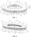
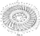
- a braking band 1 of a disc for a disc brake 2 of ventilated type is provided.
- Said braking band 1 extends between an inner diameter D1, near a rotation axis A-A of the braking band 1, and an outer diameter D2, far from said rotation axis A-A.
- Said rotation axis defines an axial direction X-X.
- Said braking band 1 defines a radial direction R-R, which is substantially orthogonal to said axial direction X-X, and a circumferential direction C-C which is orthogonal both to said axial direction X-X and to said radial direction R-R.
- Said braking band 1 comprises two plates 3, 4 facing each other.
- Said plates 3, 4 comprise inner surfaces 5, 6, either directly or indirectly facing each other and delimiting a gap 7 which defines a ventilation conduit for the braking band 1.
- Said outer surfaces 8, 9 comprise opposite flat circumferential portions, which form braking surfaces 10, 11.
- portions of the outer surfaces 8, 9 cooperate with brake pads housed in a brake caliper to apply a braking action when sandwiched against the braking band 1.
- the portion of the outer surfaces 8, 9 which is brushed or involved by the pads defines the braking surfaces 10, 11.
- Said plates 3, 4 comprise a plate body 12, 13 having an extension in axial direction X-X or plate thickness 14, 15.
- each plate 3, 4 shows a plate thickness 14, 15 which is given by the thickness in axial direction of the plate body 12 of the plate 3, 4.
- Said connecting elements 16, 17, 18, 19 are shaped as columns and/or ribs or fins 27, which project from one plate towards the opposite plate in the shape of connecting bridges of the plates 3, 4.
- At least one of the plates 3; 4 comprises at least one ridge 20, 21, 22 which projects from said plate 3; 4 into said gap 7 without reaching the opposite plate 4; 3, thus forming at least one localized narrowing of said gap 7 and a thickening of the plate body 12; 13, thus creating a localized increase of said plate thickness 14; 15.
- Said at least one ridge 20, 21, 22 extends at least from a first connecting element 16 to an adjacent connecting element 16, thus connecting said connecting elements 16.
- Said at least one ridge 20, 21, 22 extends along said circumferential direction C-C connecting at least two adjacent connecting elements 16 arranged side-by-side in circumferential direction C-C.
- Said connecting elements 16 and said at least one ridge 20, 21, 22 may be grouped in modules 31, 32, 33, 34 distributed circumferentially C-C along said gap 7.
- At least a first module 31 comprises at least three adjacent connecting elements 16 connected to one another by two ridges 20, 21, wherein said two ridges 20, 21 are aligned circumferentially C-C and wherein said two ridges 20, 21 project from a first plate 3 into said gap 7 without reaching the opposite plate 4.
- At least a second module 32 comprises at least three adjacent connecting elements 16 connected to one another by two ridges 20, 21, wherein said two ridges 20, 21 are aligned circumferentially C-C and wherein said two ridges 20, 21 project from a second plate 4 into said gap 7 without reaching the opposite plate 3.
- At least a third module 33 comprises at least one connecting element 17 without connection at each ridge.
- At least a fourth module 34 comprises at least one connecting element 18, 19, and wherein each connecting element of said fourth module 34 remains more retracted from the band edge delimited by the outer band diameter D2 thereof than said first module 31 and/or second module.
- At least a fourth module 34 comprises at least two pairs of adjacent connecting elements 18, 19, wherein each pair 18, 19 comprises two connecting elements 18, 19 aligned one after the other along a direction which extends from the inner band diameter D1 to the outer band diameter D2.
- said connecting elements 18, 19 are fins.
- each of said pairs of fins 27 extends along a curvilinear path.
- said at least two pairs of fins 27 all have concavities having the same direction.
- At least a fourth module 34 comprises at least three pairs of adjacent connecting elements 18, 19, wherein the intermediate pair of connecting elements 18, 19, i.e. arranged side-by-side on both circumferential sides of other pairs of connecting elements, extends less radially R-R than the adjacent or circumferential end pairs.
- said at least a fourth module 34 consists of two fourth modules 34 arranged substantially angularly opposite in said gap 7.
- said first plate 3 is the plate facing the vehicle or the inner plate.
- said second plate 4 is the plate facing the wheel of the vehicle or outer plate.
- said three adjacent connecting elements 16 of said first module 31 are ribs or fins 27 which extend to be continuous from a position close to the inner band diameter D1 to a position close to the outer band diameter D2.
- said at least three adjacent connecting elements 16 of said second module 32 are ribs or fins 27 which extend to be continuous from a position close to the inner band diameter D1 to a position close to the outer band diameter D2.
- said fins 27 of said second module 32 are four in number and connected to one another by three ridges 20, 21, 22, wherein said three ridges 20, 21, 22 are aligned circumferentially C-C and wherein said three ridges 20, 21, 22 project from a second plate 4 into said gap 7 without reaching the opposite first plate 3.
- said fins 27 of said first module 31 have a cross-section, i.e. a section assessed on a plane passing through a radial direction R-R and a circumferential direction C-C, being tapered or drop-shaped, passing from the end thereof close to said outer diameter D2 to the end thereof close to said inner diameter D1.
- said fins 27 of said second module 32 have a cross-section assessed on a plane passing through a radial direction R-R and a circumferential direction C-C, being tapered or drop-shaped, passing from the end thereof close to said outer diameter D2 to the end thereof close to said inner diameter D1.
- said fins 27 of said first module 31 extend into said gap 7 along a curved path, all with the concavity having the same direction.
- said fins 27 of said second module 32 extend into said gap 7 along a curved path, all with the concavity having the same direction.
- said at least a first module 31 consists of four first modules 31.
- said at least a second module 32 consists of two second modules 32.
- said first module 31 is placed side-by-side to said second module 32 and said first and second side-by-side modules 31, 32 share a fin 27.
- said first and second modules 31, 32 form a first-and-second-module assembly, first circumferentially comprising a first module 31, then a second module 32, and then a first module 31.
- said first-and-second-module assembly is repeated twice in a braking band 1.
- said two first-and-second-module assemblies are arranged in said gap 7 in substantially angularly opposite positions from each other.
- said ridges 20, 21, 22 of first and/or second module 31, 32 are arranged close to said outer band diameter D2.
- the assembly of said ridges 20, 21, 22 extends circumferentially C-C along an annular discontinuous path, e.g. along an arc of circumference of the braking band 1, or extends circumferentially C-C over a plurality of arcs of circumference along the braking band 1, which arcs are arranged to be non-adjacent to one another.
- said at least one ridge 20, 21, 22 is a single ridge which extends over a circular sector 30 and close to the outer band diameter D2.
- At least a third module 33 comprises at least two connecting elements 17, both free from the connection to each ridge.
- said connecting elements 17 free from ridges are fins 27 which substantially extend from a position close to said band inner diameter D1 to a position close to said outer band diameter D2.
- said fins 27 are tapered or drop-shaped, passing from said outer diameter D2 to said inner diameter D1.
- said fins 27 are curved and have the same mutual concavity direction.
- the present invention further relates to a disc brake 2 comprising a braking band 1 according to any one of the embodiments described above.
- the present invention further relates to a vehicle comprising a braking band 1 according to any one of the embodiments described above.
- the set of the ridges 20, 21, 22 placed close to one another forms a group of ridges 20, 21, 22 which is arranged circumferentially, thereby creating a circumferential distribution which displays circumferential discontinuities capable of creating an uneven distribution of the set of ridges, distribution adapted to avoid the presence of natural vibration modes of the braking band 1 which, if going into resonance, would create annoying noises or squeals.
Landscapes
- Engineering & Computer Science (AREA)
- General Engineering & Computer Science (AREA)
- Mechanical Engineering (AREA)
- Braking Arrangements (AREA)
Claims (10)
- Bande de freinage (1) d'un disque (2) pour frein à disque de type ventilé,- ladite bande de freinage (1) s'étendant entre un diamètre intérieur (D1), près d'un axe de rotation (A-A) de la bande de freinage (1), et un diamètre extérieur (D2), loin dudit axe de rotation (A-A), ledit axe de rotation définissant une direction axiale (X-X) ;- ladite bande de freinage (1) définissant une direction radiale (R-R) qui est sensiblement orthogonale à ladite direction axiale (X-X), et une direction circonférentielle (C-C) qui est orthogonale à la fois à ladite direction axiale (X-X) et à ladite direction radiale (R-R) ;- ladite bande de freinage (1) comprenant deux plaques (3, 4) se faisant mutuellement face ;lesdites plaques (3, 4) comprenant des surfaces intérieures (5, 6) se faisant directement ou indirectement mutuellement face et délimitant un espace (7) ;- lesdites plaques (3, 4) comprenant des surfaces extérieures (8, 9) ;- lesdites surfaces extérieures (8, 9) comprenant des parties circonférentielles plates opposées qui forment des surfaces de freinage (10, 11) ;- lesdites plaques (3, 4) comprenant un corps de plaque (12, 13) présentant une extension dans la direction axiale (X-X) ou l'épaisseur de plaque (14, 15) ;- lesdites plaques (3, 4) étant jointes l'une à l'autre par des éléments de dissipation de chaleur ou des éléments de liaison (16, 17, 18, 19) ;- lesdits éléments de liaison (16, 17, 18, 19) prenant la forme de colonnes et/ou nervures ou ailettes (27) se projetant depuis une plaque vers la plaque opposée sous la forme de ponts de liaison des plaques (3, 4) ; dans laquelle- au moins une des plaques (3 ; 4) comprend au moins une arête (20, 21, 22) se projetant depuis ladite plaque (3 ; 4) dans ledit espace (7) sans atteindre la plaque (4 ; 3) opposée, formant ainsi au moins un rétrécissement localisé dudit espace (7) et un épaississement du corps de plaque (12 ; 13), créant ainsi une augmentation localisée de ladite épaisseur de plaque (14 ; 15) ; et dans laquelle- ladite au moins une arête (20, 21, 22) s'étend au moins depuis un premier élément de liaison (16) jusqu'à un élément de liaison (16) adjacent, reliant ainsi lesdits éléments de liaison (16) ; et dans laquelle- ladite au moins une arête (20, 21, 22) s'étend le long de ladite direction circonférentielle (C-C) reliant au moins deux éléments de liaison (16) adjacents agencés côte à côte dans la direction circonférentielle (C-C) ; et dans laquelle- lesdits éléments de liaison (16) et ladite au moins une arête (20, 21, 22) peuvent être regroupés en modules (31, 32, 33, 34) répartis circonférentiellement (C-C) le long dudit espace (7) ;caractérisé en ce que- au moins un premier module (31) comprend au moins trois éléments de liaison (16) adjacents reliés les uns aux autres par deux arêtes (20, 21), dans laquelle lesdites deux arêtes (20, 21) sont alignées circonférentiellement (C-C) et dans laquelle lesdites deux arêtes (20, 21) se projettent depuis une première plaque (3) dans ledit espace (7) sans atteindre la plaque (4) opposée,et dans laquelle- au moins un deuxième module (32) comprend au moins trois éléments de liaison (16) adjacents reliés les uns aux autres par deux arêtes (20, 21), dans laquelle lesdites deux arêtes (20, 21) sont alignées circonférentiellement (C-C) et dans laquelle lesdites deux arêtes (20, 21) se projettent depuis une deuxième plaque (4) dans ledit espace (7) sans atteindre la plaque (3) opposée,et dans laquelle- au moins un troisième module (33) comprend au moins un élément de liaison (17) sans liaison au niveau de chaque arête.
- Bande de freinage (1) selon la revendication 1, dans laquelle- au moins un quatrième module (34) comprend au moins un élément de liaison (18, 19), et dans laquelle chaque élément de liaison dudit quatrième module (34) reste plus rétracté depuis le bord de bande délimité par le diamètre de bande extérieur (D2) de celui-ci que ledit premier module (31) et/ou ledit deuxième module ; et/ou dans laquelle- au moins un quatrième module (34) comprend au moins deux paires d'éléments de liaison (18, 19) adjacents, dans laquelle chaque paire (18, 19) comprend deux éléments de liaison (18, 19) alignés l'un après l'autre le long d'une direction qui s'étend depuis le diamètre de bande intérieur (D1) jusqu'au diamètre de bande extérieur (D2) ; et/ou dans laquelle- lesdits éléments de liaison (18, 19) sont des ailettes ; et/ou dans laquelle- chacune desdites paires d'ailettes (27) s'étend le long d'un chemin curviligne ; et/ou dans laquelle- lesdites au moins deux paires d'ailettes (27) présentent toutes des concavités présentant la même direction.
- Bande de freinage (1) selon l'une des revendications précédentes, dans laquelle :- au moins un quatrième module (34) comprend au moins trois paires d'éléments de liaison (18, 19) adjacents dans laquelle la paire intermédiaire d'éléments de liaison (18, 19), c'est-à-dire agencés côte à côte sur les deux côtés circonférentiels d'autres paires d'éléments de liaison, s'étend moins radialement (R-R) que les paires d'extrémité circonférentielles ou adjacentes ; et/ou dans laquelle- ledit au moins un quatrième module (34) est constitué de deux quatrièmes modules (34) agencés de manière sensiblement angulairement opposée dans ledit espace (7).
- Bande de freinage (1) selon l'une des revendications précédentes, dans laquelle :- ladite première plaque (3) est la plaque faisant face au véhicule ou la plaque intérieure ; et/ou dans laquelle- ladite deuxième plaque (4) est la plaque faisant face à la roue du véhicule ou la plaque extérieure ; et/ou dans laquelle- lesdits trois éléments de liaison (16) adjacents dudit premier module (31) sont des nervures ou ailettes (27) qui s'étendent pour être continues depuis une position près du diamètre de bande intérieur (D1) jusqu'à une position près du diamètre de bande extérieur (D2).
- Bande de freinage (1) selon l'une des revendications précédentes, dans laquelle lesdits au moins trois éléments de liaison (16) adjacents dudit deuxième module (32) sont des nervures ou ailettes (27) qui s'étendent pour être continues depuis une position près du diamètre de bande intérieur (D1) jusqu'à une position près du diamètre de bande extérieur (D2) ; et/ou dans laquelle- lesdites ailettes (27) dudit deuxième module (32) sont au nombre de quatre et reliées les unes aux autres par trois arêtes (20, 21, 22), dans laquelle lesdites trois arêtes (20, 21, 22) sont alignées circonférentiellement (C-C) et dans laquelle lesdites trois arêtes (20, 21, 22) se projettent depuis une deuxième plaque (4) dans ledit espace (7) sans atteindre la première plaque (3) opposée ; et/ou/ dans laquelle- lesdites ailettes (27) dudit premier module (31) présentent une section transversale, c'est-à-dire une section évaluée sur un plan passant par une direction radiale (R-R) et une direction circonférentielle (C-C), étant conique ou en forme de goutte, passant de l'extrémité de celles-ci près dudit diamètre extérieur (D2) à l'extrémité de celles-ci près dudit diamètre intérieur (D1) ; et/ou dans laquelle- lesdites ailettes (27) dudit deuxième module (32) présentent une section transversale évaluée sur un plan passant par une direction radiale (R-R) et une direction circonférentielle (C-C), étant conique ou en forme de goutte, passant de l'extrémité de celles-ci près dudit diamètre extérieur (D2) à l'extrémité de celles-ci près dudit diamètre intérieur (D1) ; et/ou dans laquelle- lesdites ailettes (27) dudit premier module (31) s'étendent dans ledit espace (7) le long d'un chemin incurvé, toutes avec la concavité présentant la même direction ; et/ou dans laquelle- lesdites ailettes (27) dudit deuxième module (32) s'étendent dans ledit espace (7) le long d'un chemin incurvé, toutes avec la concavité présentant la même direction.
- Bande de freinage (1) selon l'une des revendications précédentes, dans laquelle :- ledit au moins un premier module (31) est constitué de quatre premiers modules (31) ; et/ou dans laquelle- ledit au moins un deuxième module (32) est constitué de deux deuxièmes modules (32) ; et/ou dans laquelle- ledit premier module (31) est placé côte à côte par rapport audit deuxième module (32) et lesdits premier et deuxième modules (31, 32) côte à côte partagent une ailette (27) ; et/ou dans laquelle- lesdits premier et deuxième modules (31, 32) forment un ensemble à premier et deuxième modules, d'abord comprenant circonférentiellement un premier module (31), puis un deuxième module (32), et ensuite un premier module (31) ; et/ou dans laquelle- ledit ensemble à premier et deuxième modules est répété deux fois dans une bande de freinage (1) ; et/ou dans laquelle- lesdits deux ensembles à premier et deuxième modules sont agencés dans ledit espace (7) dans des positions sensiblement angulairement opposées l'un par rapport à l'autre.
- Bande de freinage (1) selon l'une des revendications précédentes, dans laquelle :- lesdites arêtes (20, 21, 22) du premier et/ou deuxième module (31, 32) sont agencées près dudit diamètre de bande extérieur (D2) ; et/ou dans laquelle- d'autres arêtes en dehors des arêtes (20, 21, 22) placées près dudit diamètre de bande extérieur (D2) sont évitées entre lesdits éléments de liaison (16) dudit premier et/ou dudit deuxième module (31, 32) ; et/ou dans laquelle- l'ensemble desdites arêtes (20, 21, 22) s'étend circonférentiellement (C-C) le long d'un chemin discontinu annulaire, par exemple le long d'un arc de circonférence de la bande de freinage (1), ou s'étend circonférentiellement (C-C) sur une pluralité d'arcs de circonférence le long de la bande de freinage (1), lesquels arcs sont agencés pour être non adjacents les uns aux autres ; et/ou dans laquelle- ladite au moins une arête (20, 21, 22) est une arête unique qui s'étend sur un secteur circulaire (30) et près du diamètre de bande extérieur (D2).
- Bande de freinage (1) selon l'une des revendications précédentes, dans laquelle :- au moins un troisième module (33) comprend au moins deux éléments de liaison (17), tous deux dépourvus de la liaison à chaque arête et/ou dans laquelle- lesdits éléments de liaison (17) dépourvus d'arêtes sont des ailettes (27) qui s'étendent sensiblement depuis une position près dudit diamètre de bande intérieur (D1) jusqu'à une position près dudit diamètre de bande extérieur (D2) ; et/ou dans laquelle- lesdites ailettes (27) sont coniques ou en forme de goutte, passant dudit diamètre extérieur (D2) audit diamètre intérieur (D1) ; et/ou dans laquelle- lesdites ailettes (27) sont incurvées et présentent la même direction de concavité mutuelle.
- Disque (2) pour frein à disque comprenant une bande de freinage (1) selon l'une quelconque des revendications précédentes.
- Véhicule comprenant une bande de freinage (1) selon l'une quelconque des revendications précédentes.
Applications Claiming Priority (2)
| Application Number | Priority Date | Filing Date | Title |
|---|---|---|---|
| IT102018000020128A IT201800020128A1 (it) | 2018-12-18 | 2018-12-18 | Fascia di frenatura di un disco per freno a disco di tipo ventilato |
| PCT/IB2019/060481 WO2020128705A1 (fr) | 2018-12-18 | 2019-12-05 | Bande de freinage d'un disque pour frein à disque de type ventilé |
Publications (2)
| Publication Number | Publication Date |
|---|---|
| EP3899308A1 EP3899308A1 (fr) | 2021-10-27 |
| EP3899308B1 true EP3899308B1 (fr) | 2023-04-26 |
Family
ID=66049453
Family Applications (1)
| Application Number | Title | Priority Date | Filing Date |
|---|---|---|---|
| EP19817425.2A Active EP3899308B1 (fr) | 2018-12-18 | 2019-12-05 | Bande de freinage d'un disque pour frein à disque de type ventilé |
Country Status (6)
| Country | Link |
|---|---|
| US (1) | US11846334B2 (fr) |
| EP (1) | EP3899308B1 (fr) |
| JP (1) | JP7605740B2 (fr) |
| CN (1) | CN113227599B (fr) |
| IT (1) | IT201800020128A1 (fr) |
| WO (1) | WO2020128705A1 (fr) |
Families Citing this family (1)
| Publication number | Priority date | Publication date | Assignee | Title |
|---|---|---|---|---|
| CN114838069B (zh) * | 2022-04-25 | 2023-06-23 | 邓爽 | 一种汽车制动盘 |
Family Cites Families (54)
| Publication number | Priority date | Publication date | Assignee | Title |
|---|---|---|---|---|
| DE2425438A1 (de) | 1974-05-25 | 1975-12-04 | Knorr Bremse Gmbh | Scheibenbremse, insbesondere fuer schienenfahrzeuge |
| US4523666A (en) | 1983-08-03 | 1985-06-18 | Motor Wheel Corporation | Brake rotor with vibration harmonic suppression, and method of manufacture |
| IT206836Z2 (it) | 1986-06-20 | 1987-10-01 | Brembo Spa | Disco autoventilato per freni a disco. |
| DE3740912A1 (de) | 1987-12-03 | 1989-06-15 | Buderus Kundenguss | Verwendung einer gusseisensorte fuer bremsenkoerper |
| US5004078A (en) | 1988-11-09 | 1991-04-02 | Aisin Takaoka Co., Ltd. | Ventilated disk and process for making same |
| JP3252157B2 (ja) | 1992-07-15 | 2002-01-28 | 株式会社豊田中央研究所 | ブレーキディスクロータ |
| JP3170763B2 (ja) | 1992-09-17 | 2001-05-28 | 株式会社豊田中央研究所 | ブレーキディスクロータ |
| IT1273754B (it) | 1994-02-11 | 1997-07-10 | Brembo Spa | Disco di un freno a disco per autovetture ad elevate prestazioni |
| JP3521266B2 (ja) | 1994-09-08 | 2004-04-19 | 株式会社豊田中央研究所 | ブレーキディスクロータ |
| FR2728945A1 (fr) * | 1994-12-28 | 1996-07-05 | Renault Vehicules Ind | Disque de frein ventile a structure composite |
| US5542503A (en) | 1995-06-06 | 1996-08-06 | Kelsey-Hayes Company | Rotor for disc brake assembly |
| JP3450158B2 (ja) * | 1996-07-24 | 2003-09-22 | トヨタ自動車株式会社 | ディスクブレーキ用ディスクロータ |
| JPH10318302A (ja) | 1997-05-22 | 1998-12-04 | Nissan Motor Co Ltd | ブレーキディスクロータ |
| US6131707A (en) | 1997-06-04 | 2000-10-17 | Kelsey-Hayes Company | Disc brake rotor and method for producing same |
| JP3480264B2 (ja) | 1997-09-18 | 2003-12-15 | 日産自動車株式会社 | ベンチレーテッドロータ |
| JPH11287268A (ja) | 1998-04-03 | 1999-10-19 | Kiriu Mach Mfg Co Ltd | ベンチレーテッド型ブレーキディスクロータ |
| JP3777811B2 (ja) | 1998-07-29 | 2006-05-24 | 日産自動車株式会社 | ブレーキディスクロータ |
| JP4392889B2 (ja) * | 1999-02-19 | 2010-01-06 | サンスター技研株式会社 | ディスクブレーキ用プレート |
| JP2000310263A (ja) * | 1999-04-27 | 2000-11-07 | Tokico Ltd | ディスクロータ |
| JP4298099B2 (ja) | 1999-12-07 | 2009-07-15 | 曙ブレーキ工業株式会社 | ベンチレーテッド型ディスク |
| AUPR304801A0 (en) | 2001-02-12 | 2001-03-08 | Disc Brakes Australia Pty. Ltd. | An improved rotor for self-ventilating disc brakes |
| WO2002073060A1 (fr) | 2001-03-14 | 2002-09-19 | Freni Brembo S.P.A. | Bande de freinage et disque pour frein a disque |
| US7690484B2 (en) | 2001-04-06 | 2010-04-06 | Freni Brembo S.P.A. | Braking band, a ventilated disk-brake disk, and a core box for the production of a disk-brake disk core |
| US7066306B2 (en) | 2001-05-10 | 2006-06-27 | Stephen Patrick Gavin | Self-ventilating disc brake rotor |
| JP4166687B2 (ja) * | 2001-05-28 | 2008-10-15 | フレニ・ブレンボ エス・ピー・エー | ブレーキディスク用の制動バンド |
| ATE478275T1 (de) | 2003-05-15 | 2010-09-15 | Freni Brembo Spa | Innenbelüftete bremsscheibe für scheibenbremsen |
| AU2003234062A1 (en) | 2003-05-15 | 2004-12-03 | Freni Brembo S.P.A. | Ventilated disc braking band for a disc brake |
| US6945309B2 (en) * | 2003-07-18 | 2005-09-20 | Hayes Lemmerz International, Inc. | Method and apparatus for forming a part with dampener |
| EP1805430B8 (fr) * | 2004-10-26 | 2015-12-30 | Freni Brembo S.p.A. | Disque pour frein à disque |
| US8668058B2 (en) | 2005-03-30 | 2014-03-11 | Federal-Mogul Worldwide, Inc. | Vented disc brake rotor |
| US7410034B1 (en) * | 2006-01-17 | 2008-08-12 | Robert Bosch Gmbh | Drum brake |
| JP4600306B2 (ja) * | 2006-01-31 | 2010-12-15 | 住友金属工業株式会社 | 鉄道車両用ブレーキディスク |
| US20080067018A1 (en) | 2006-09-19 | 2008-03-20 | Alcon Components Limited | Brake disk |
| ITMI20070881A1 (it) * | 2007-05-03 | 2008-11-04 | Freni Brembo Spa | Disco freno ventilato |
| ITBS20070067A1 (it) * | 2007-05-03 | 2008-11-04 | Freni Brembo Spa | Disco freno ventilato |
| US20090000884A1 (en) | 2007-06-26 | 2009-01-01 | Akebono Corporation (North America) | Brake rotor |
| US20100122880A1 (en) | 2008-11-17 | 2010-05-20 | Gm Global Technology Operations, Inc. | Surface configurations for damping inserts |
| US20090035598A1 (en) | 2007-08-03 | 2009-02-05 | Gm Global Technology Operations, Inc. | Product with metallic foam and method of manufacturing the same |
| US8336682B2 (en) * | 2007-08-31 | 2012-12-25 | Honda Motor Co., Ltd. | Ventilated brake disk and method |
| EP2276946B1 (fr) * | 2008-05-05 | 2011-10-26 | Freni Brembo S.p.A. | Bande de freinage d'un disque pour un frein à disque de type ventilé |
| US9175733B2 (en) | 2009-04-02 | 2015-11-03 | Ford Global Technologies, Llc | Transmission clutch assemblies with squawk reduction techniques |
| IT1395120B1 (it) * | 2009-07-29 | 2012-09-05 | Freni Brembo Spa | Fascia di frenatura e disco per freno a disco |
| IT1396228B1 (it) | 2009-11-13 | 2012-11-16 | Freni Brembo Spa | Fascia di frenatura di un disco per freno a disco di tipo ventilato |
| DE102012009900A1 (de) * | 2012-05-18 | 2013-11-21 | Knorr-Bremse Systeme für Nutzfahrzeuge GmbH | Verschleißnachstellvorrichtung einer Scheibenbremse und entsprechende Scheibenbremse |
| US9371875B2 (en) | 2014-06-09 | 2016-06-21 | Ford Global Technologies, Llc | Ventilated brake rotors |
| CN107110263B (zh) | 2014-08-05 | 2019-11-29 | 福乐尼·乐姆宝公开有限公司 | 用于盘式制动器的盘的制动带 |
| DE102014222648B4 (de) | 2014-11-06 | 2022-09-15 | Bayerische Motoren Werke Aktiengesellschaft | Bremsscheibe mit Innenbelüftung |
| ES2753411T3 (es) * | 2014-12-12 | 2020-04-08 | Piaggio&C S P A | Disco para un freno de disco del tipo ventilado, dispositivo y método para mejorar la eficiencia de un disco para un freno de disco del tipo ventilado |
| ITUA20161413A1 (it) | 2016-03-07 | 2017-09-07 | Freni Brembo Spa | Fascia frenante ventilata, disco freno ventilato e metodo di ventilazione |
| ITUA20161411A1 (it) | 2016-03-07 | 2017-09-07 | Freni Brembo Spa | Fascia frenante ventilata, assieme di disco freno ventilato e metodo di ventilazione |
| WO2017182051A1 (fr) * | 2016-04-18 | 2017-10-26 | Volvo Truck Corporation | Disque de frein structuré |
| CN206636962U (zh) * | 2017-01-19 | 2017-11-14 | 山东昊安金科新材料股份有限公司 | 一种高速列车制动盘—轮盘 |
| CN207034033U (zh) * | 2017-08-07 | 2018-02-23 | 浙江力邦合信智能制动系统股份有限公司 | 一种通风式汽车制动盘 |
| IT201800002652A1 (it) * | 2018-02-13 | 2019-08-13 | Freni Brembo Spa | Fascia di frenatura di un disco per freno a disco di tipo ventilato |
-
2018
- 2018-12-18 IT IT102018000020128A patent/IT201800020128A1/it unknown
-
2019
- 2019-12-05 US US17/415,106 patent/US11846334B2/en active Active
- 2019-12-05 EP EP19817425.2A patent/EP3899308B1/fr active Active
- 2019-12-05 JP JP2021535089A patent/JP7605740B2/ja active Active
- 2019-12-05 WO PCT/IB2019/060481 patent/WO2020128705A1/fr not_active Ceased
- 2019-12-05 CN CN201980083975.6A patent/CN113227599B/zh active Active
Also Published As
| Publication number | Publication date |
|---|---|
| IT201800020128A1 (it) | 2020-06-18 |
| CN113227599B (zh) | 2023-08-04 |
| JP7605740B2 (ja) | 2024-12-24 |
| US11846334B2 (en) | 2023-12-19 |
| JP2022515099A (ja) | 2022-02-17 |
| CN113227599A (zh) | 2021-08-06 |
| US20220042564A1 (en) | 2022-02-10 |
| EP3899308A1 (fr) | 2021-10-27 |
| WO2020128705A1 (fr) | 2020-06-25 |
Similar Documents
| Publication | Publication Date | Title |
|---|---|---|
| US10024377B2 (en) | Ventilated brake disc | |
| EP4010607B1 (fr) | Bande de freinage d'un disque pour frein à disque de type ventilé | |
| EP3752751B1 (fr) | Bande de freinage de disque pour frein à disque de type ventilé | |
| EP4010230B1 (fr) | Bande de freinage d'un disque pour frein à disque de type ventilé | |
| EP3899308B1 (fr) | Bande de freinage d'un disque pour frein à disque de type ventilé | |
| US12234872B2 (en) | Braking band of a disc for disc brake of ventilated type | |
| EP4045813B1 (fr) | Bande de freinage d'un disque pour frein à disque de type ventilé |
Legal Events
| Date | Code | Title | Description |
|---|---|---|---|
| STAA | Information on the status of an ep patent application or granted ep patent |
Free format text: STATUS: UNKNOWN |
|
| STAA | Information on the status of an ep patent application or granted ep patent |
Free format text: STATUS: THE INTERNATIONAL PUBLICATION HAS BEEN MADE |
|
| PUAI | Public reference made under article 153(3) epc to a published international application that has entered the european phase |
Free format text: ORIGINAL CODE: 0009012 |
|
| STAA | Information on the status of an ep patent application or granted ep patent |
Free format text: STATUS: REQUEST FOR EXAMINATION WAS MADE |
|
| 17P | Request for examination filed |
Effective date: 20210616 |
|
| AK | Designated contracting states |
Kind code of ref document: A1 Designated state(s): AL AT BE BG CH CY CZ DE DK EE ES FI FR GB GR HR HU IE IS IT LI LT LU LV MC MK MT NL NO PL PT RO RS SE SI SK SM TR |
|
| DAV | Request for validation of the european patent (deleted) | ||
| DAX | Request for extension of the european patent (deleted) | ||
| GRAP | Despatch of communication of intention to grant a patent |
Free format text: ORIGINAL CODE: EPIDOSNIGR1 |
|
| STAA | Information on the status of an ep patent application or granted ep patent |
Free format text: STATUS: GRANT OF PATENT IS INTENDED |
|
| INTG | Intention to grant announced |
Effective date: 20221118 |
|
| GRAS | Grant fee paid |
Free format text: ORIGINAL CODE: EPIDOSNIGR3 |
|
| GRAA | (expected) grant |
Free format text: ORIGINAL CODE: 0009210 |
|
| STAA | Information on the status of an ep patent application or granted ep patent |
Free format text: STATUS: THE PATENT HAS BEEN GRANTED |
|
| AK | Designated contracting states |
Kind code of ref document: B1 Designated state(s): AL AT BE BG CH CY CZ DE DK EE ES FI FR GB GR HR HU IE IS IT LI LT LU LV MC MK MT NL NO PL PT RO RS SE SI SK SM TR |
|
| REG | Reference to a national code |
Ref country code: GB Ref legal event code: FG4D |
|
| REG | Reference to a national code |
Ref country code: CH Ref legal event code: EP |
|
| REG | Reference to a national code |
Ref country code: DE Ref legal event code: R096 Ref document number: 602019028131 Country of ref document: DE |
|
| REG | Reference to a national code |
Ref country code: AT Ref legal event code: REF Ref document number: 1563030 Country of ref document: AT Kind code of ref document: T Effective date: 20230515 |
|
| REG | Reference to a national code |
Ref country code: IE Ref legal event code: FG4D |
|
| REG | Reference to a national code |
Ref country code: LT Ref legal event code: MG9D |
|
| P01 | Opt-out of the competence of the unified patent court (upc) registered |
Effective date: 20230726 |
|
| REG | Reference to a national code |
Ref country code: NL Ref legal event code: MP Effective date: 20230426 |
|
| REG | Reference to a national code |
Ref country code: AT Ref legal event code: MK05 Ref document number: 1563030 Country of ref document: AT Kind code of ref document: T Effective date: 20230426 |
|
| PG25 | Lapsed in a contracting state [announced via postgrant information from national office to epo] |
Ref country code: NL Free format text: LAPSE BECAUSE OF FAILURE TO SUBMIT A TRANSLATION OF THE DESCRIPTION OR TO PAY THE FEE WITHIN THE PRESCRIBED TIME-LIMIT Effective date: 20230426 |
|
| PG25 | Lapsed in a contracting state [announced via postgrant information from national office to epo] |
Ref country code: SE Free format text: LAPSE BECAUSE OF FAILURE TO SUBMIT A TRANSLATION OF THE DESCRIPTION OR TO PAY THE FEE WITHIN THE PRESCRIBED TIME-LIMIT Effective date: 20230426 Ref country code: PT Free format text: LAPSE BECAUSE OF FAILURE TO SUBMIT A TRANSLATION OF THE DESCRIPTION OR TO PAY THE FEE WITHIN THE PRESCRIBED TIME-LIMIT Effective date: 20230828 Ref country code: NO Free format text: LAPSE BECAUSE OF FAILURE TO SUBMIT A TRANSLATION OF THE DESCRIPTION OR TO PAY THE FEE WITHIN THE PRESCRIBED TIME-LIMIT Effective date: 20230726 Ref country code: ES Free format text: LAPSE BECAUSE OF FAILURE TO SUBMIT A TRANSLATION OF THE DESCRIPTION OR TO PAY THE FEE WITHIN THE PRESCRIBED TIME-LIMIT Effective date: 20230426 Ref country code: AT Free format text: LAPSE BECAUSE OF FAILURE TO SUBMIT A TRANSLATION OF THE DESCRIPTION OR TO PAY THE FEE WITHIN THE PRESCRIBED TIME-LIMIT Effective date: 20230426 |
|
| PG25 | Lapsed in a contracting state [announced via postgrant information from national office to epo] |
Ref country code: RS Free format text: LAPSE BECAUSE OF FAILURE TO SUBMIT A TRANSLATION OF THE DESCRIPTION OR TO PAY THE FEE WITHIN THE PRESCRIBED TIME-LIMIT Effective date: 20230426 Ref country code: PL Free format text: LAPSE BECAUSE OF FAILURE TO SUBMIT A TRANSLATION OF THE DESCRIPTION OR TO PAY THE FEE WITHIN THE PRESCRIBED TIME-LIMIT Effective date: 20230426 Ref country code: LV Free format text: LAPSE BECAUSE OF FAILURE TO SUBMIT A TRANSLATION OF THE DESCRIPTION OR TO PAY THE FEE WITHIN THE PRESCRIBED TIME-LIMIT Effective date: 20230426 Ref country code: LT Free format text: LAPSE BECAUSE OF FAILURE TO SUBMIT A TRANSLATION OF THE DESCRIPTION OR TO PAY THE FEE WITHIN THE PRESCRIBED TIME-LIMIT Effective date: 20230426 Ref country code: IS Free format text: LAPSE BECAUSE OF FAILURE TO SUBMIT A TRANSLATION OF THE DESCRIPTION OR TO PAY THE FEE WITHIN THE PRESCRIBED TIME-LIMIT Effective date: 20230826 Ref country code: HR Free format text: LAPSE BECAUSE OF FAILURE TO SUBMIT A TRANSLATION OF THE DESCRIPTION OR TO PAY THE FEE WITHIN THE PRESCRIBED TIME-LIMIT Effective date: 20230426 Ref country code: GR Free format text: LAPSE BECAUSE OF FAILURE TO SUBMIT A TRANSLATION OF THE DESCRIPTION OR TO PAY THE FEE WITHIN THE PRESCRIBED TIME-LIMIT Effective date: 20230727 |
|
| PG25 | Lapsed in a contracting state [announced via postgrant information from national office to epo] |
Ref country code: FI Free format text: LAPSE BECAUSE OF FAILURE TO SUBMIT A TRANSLATION OF THE DESCRIPTION OR TO PAY THE FEE WITHIN THE PRESCRIBED TIME-LIMIT Effective date: 20230426 |
|
| PG25 | Lapsed in a contracting state [announced via postgrant information from national office to epo] |
Ref country code: SK Free format text: LAPSE BECAUSE OF FAILURE TO SUBMIT A TRANSLATION OF THE DESCRIPTION OR TO PAY THE FEE WITHIN THE PRESCRIBED TIME-LIMIT Effective date: 20230426 |
|
| REG | Reference to a national code |
Ref country code: DE Ref legal event code: R097 Ref document number: 602019028131 Country of ref document: DE |
|
| PG25 | Lapsed in a contracting state [announced via postgrant information from national office to epo] |
Ref country code: SM Free format text: LAPSE BECAUSE OF FAILURE TO SUBMIT A TRANSLATION OF THE DESCRIPTION OR TO PAY THE FEE WITHIN THE PRESCRIBED TIME-LIMIT Effective date: 20230426 Ref country code: SK Free format text: LAPSE BECAUSE OF FAILURE TO SUBMIT A TRANSLATION OF THE DESCRIPTION OR TO PAY THE FEE WITHIN THE PRESCRIBED TIME-LIMIT Effective date: 20230426 Ref country code: RO Free format text: LAPSE BECAUSE OF FAILURE TO SUBMIT A TRANSLATION OF THE DESCRIPTION OR TO PAY THE FEE WITHIN THE PRESCRIBED TIME-LIMIT Effective date: 20230426 Ref country code: EE Free format text: LAPSE BECAUSE OF FAILURE TO SUBMIT A TRANSLATION OF THE DESCRIPTION OR TO PAY THE FEE WITHIN THE PRESCRIBED TIME-LIMIT Effective date: 20230426 Ref country code: DK Free format text: LAPSE BECAUSE OF FAILURE TO SUBMIT A TRANSLATION OF THE DESCRIPTION OR TO PAY THE FEE WITHIN THE PRESCRIBED TIME-LIMIT Effective date: 20230426 Ref country code: CZ Free format text: LAPSE BECAUSE OF FAILURE TO SUBMIT A TRANSLATION OF THE DESCRIPTION OR TO PAY THE FEE WITHIN THE PRESCRIBED TIME-LIMIT Effective date: 20230426 |
|
| PLBE | No opposition filed within time limit |
Free format text: ORIGINAL CODE: 0009261 |
|
| STAA | Information on the status of an ep patent application or granted ep patent |
Free format text: STATUS: NO OPPOSITION FILED WITHIN TIME LIMIT |
|
| 26N | No opposition filed |
Effective date: 20240129 |
|
| PG25 | Lapsed in a contracting state [announced via postgrant information from national office to epo] |
Ref country code: SI Free format text: LAPSE BECAUSE OF FAILURE TO SUBMIT A TRANSLATION OF THE DESCRIPTION OR TO PAY THE FEE WITHIN THE PRESCRIBED TIME-LIMIT Effective date: 20230426 |
|
| PG25 | Lapsed in a contracting state [announced via postgrant information from national office to epo] |
Ref country code: SI Free format text: LAPSE BECAUSE OF FAILURE TO SUBMIT A TRANSLATION OF THE DESCRIPTION OR TO PAY THE FEE WITHIN THE PRESCRIBED TIME-LIMIT Effective date: 20230426 |
|
| REG | Reference to a national code |
Ref country code: CH Ref legal event code: PL |
|
| PG25 | Lapsed in a contracting state [announced via postgrant information from national office to epo] |
Ref country code: LU Free format text: LAPSE BECAUSE OF NON-PAYMENT OF DUE FEES Effective date: 20231205 |
|
| PG25 | Lapsed in a contracting state [announced via postgrant information from national office to epo] |
Ref country code: MC Free format text: LAPSE BECAUSE OF FAILURE TO SUBMIT A TRANSLATION OF THE DESCRIPTION OR TO PAY THE FEE WITHIN THE PRESCRIBED TIME-LIMIT Effective date: 20230426 |
|
| REG | Reference to a national code |
Ref country code: BE Ref legal event code: MM Effective date: 20231231 |
|
| PG25 | Lapsed in a contracting state [announced via postgrant information from national office to epo] |
Ref country code: MC Free format text: LAPSE BECAUSE OF FAILURE TO SUBMIT A TRANSLATION OF THE DESCRIPTION OR TO PAY THE FEE WITHIN THE PRESCRIBED TIME-LIMIT Effective date: 20230426 Ref country code: LU Free format text: LAPSE BECAUSE OF NON-PAYMENT OF DUE FEES Effective date: 20231205 |
|
| REG | Reference to a national code |
Ref country code: IE Ref legal event code: MM4A |
|
| PG25 | Lapsed in a contracting state [announced via postgrant information from national office to epo] |
Ref country code: IE Free format text: LAPSE BECAUSE OF NON-PAYMENT OF DUE FEES Effective date: 20231205 |
|
| PG25 | Lapsed in a contracting state [announced via postgrant information from national office to epo] |
Ref country code: BE Free format text: LAPSE BECAUSE OF NON-PAYMENT OF DUE FEES Effective date: 20231231 |
|
| PG25 | Lapsed in a contracting state [announced via postgrant information from national office to epo] |
Ref country code: CH Free format text: LAPSE BECAUSE OF NON-PAYMENT OF DUE FEES Effective date: 20231231 |
|
| PG25 | Lapsed in a contracting state [announced via postgrant information from national office to epo] |
Ref country code: IE Free format text: LAPSE BECAUSE OF NON-PAYMENT OF DUE FEES Effective date: 20231205 Ref country code: CH Free format text: LAPSE BECAUSE OF NON-PAYMENT OF DUE FEES Effective date: 20231231 Ref country code: BE Free format text: LAPSE BECAUSE OF NON-PAYMENT OF DUE FEES Effective date: 20231231 |
|
| PG25 | Lapsed in a contracting state [announced via postgrant information from national office to epo] |
Ref country code: BG Free format text: LAPSE BECAUSE OF FAILURE TO SUBMIT A TRANSLATION OF THE DESCRIPTION OR TO PAY THE FEE WITHIN THE PRESCRIBED TIME-LIMIT Effective date: 20230426 |
|
| PG25 | Lapsed in a contracting state [announced via postgrant information from national office to epo] |
Ref country code: BG Free format text: LAPSE BECAUSE OF FAILURE TO SUBMIT A TRANSLATION OF THE DESCRIPTION OR TO PAY THE FEE WITHIN THE PRESCRIBED TIME-LIMIT Effective date: 20230426 |
|
| PG25 | Lapsed in a contracting state [announced via postgrant information from national office to epo] |
Ref country code: CY Free format text: LAPSE BECAUSE OF FAILURE TO SUBMIT A TRANSLATION OF THE DESCRIPTION OR TO PAY THE FEE WITHIN THE PRESCRIBED TIME-LIMIT; INVALID AB INITIO Effective date: 20191205 |
|
| PG25 | Lapsed in a contracting state [announced via postgrant information from national office to epo] |
Ref country code: HU Free format text: LAPSE BECAUSE OF FAILURE TO SUBMIT A TRANSLATION OF THE DESCRIPTION OR TO PAY THE FEE WITHIN THE PRESCRIBED TIME-LIMIT; INVALID AB INITIO Effective date: 20191205 |
|
| PG25 | Lapsed in a contracting state [announced via postgrant information from national office to epo] |
Ref country code: TR Free format text: LAPSE BECAUSE OF FAILURE TO SUBMIT A TRANSLATION OF THE DESCRIPTION OR TO PAY THE FEE WITHIN THE PRESCRIBED TIME-LIMIT Effective date: 20230426 |
|
| PGFP | Annual fee paid to national office [announced via postgrant information from national office to epo] |
Ref country code: GB Payment date: 20251219 Year of fee payment: 7 |
|
| PGFP | Annual fee paid to national office [announced via postgrant information from national office to epo] |
Ref country code: IT Payment date: 20251007 Year of fee payment: 7 |
|
| PGFP | Annual fee paid to national office [announced via postgrant information from national office to epo] |
Ref country code: FR Payment date: 20251128 Year of fee payment: 7 |
|
| PGFP | Annual fee paid to national office [announced via postgrant information from national office to epo] |
Ref country code: DE Payment date: 20251222 Year of fee payment: 7 |