EP4012131A1 - Befestigungseinrichtung und verfahren zur ausrichtung und fixierung eines pfostenprofils einer pfosten-riegel-konstruktion - Google Patents
Befestigungseinrichtung und verfahren zur ausrichtung und fixierung eines pfostenprofils einer pfosten-riegel-konstruktion Download PDFInfo
- Publication number
- EP4012131A1 EP4012131A1 EP21207046.0A EP21207046A EP4012131A1 EP 4012131 A1 EP4012131 A1 EP 4012131A1 EP 21207046 A EP21207046 A EP 21207046A EP 4012131 A1 EP4012131 A1 EP 4012131A1
- Authority
- EP
- European Patent Office
- Prior art keywords
- fastening device
- profile
- fastening
- post profile
- post
- Prior art date
- Legal status (The legal status is an assumption and is not a legal conclusion. Google has not performed a legal analysis and makes no representation as to the accuracy of the status listed.)
- Granted
Links
Images


Classifications
-
- E—FIXED CONSTRUCTIONS
- E04—BUILDING
- E04B—GENERAL BUILDING CONSTRUCTIONS; WALLS, e.g. PARTITIONS; ROOFS; FLOORS; CEILINGS; INSULATION OR OTHER PROTECTION OF BUILDINGS
- E04B2/00—Walls, e.g. partitions, for buildings; Wall construction with regard to insulation; Connections specially adapted to walls
- E04B2/88—Curtain walls
- E04B2/96—Curtain walls comprising panels attached to the structure through mullions or transoms
Definitions
- the invention relates to a fastening device and a method for aligning and fixing a mullion profile of a mullion-transom construction.
- a generic fastening device for aligning and fixing a post profile is known.
- This has a base plate that can be fixed to the substructure by means of fastening screws and has vertical guide tracks and a receiving shoe, which is guided over the guide tracks on the base plate, for fastening the post profile.
- the base plate contains webs that project vertically upwards, between which the guide tracks for guiding the receiving shoe are delimited.
- the receiving shoe which is U-shaped in a vertical section, is equipped with side walls which have guide pieces on their outside for engaging in the guide tracks of the base plate.
- the post profile is inserted between the side walls of the mounting shoe and fixed with two parallel threaded bolts.
- the bottom plate is designed in such a way that it can be adjusted in its longitudinal direction and in a direction running transversely to its fastening screws.
- an adjusting screw is used, which is supported with its head on the base plate and extends with its shank through a hole in the base of the receiving shoe and in a one-piece strip with the base. This allows a post profile to be aligned and fixed in three mutually orthogonal axes.
- the fastening device is relatively complex and requires a high level of design and manufacturing complexity.
- the object of the invention is to create a fastening device and a method for aligning and fixing a mullion profile of a mullion-transom construction, which allow simple and cost-effective fastening of a mullion profile with high positioning accuracy.
- the holding part is designed as a slide-in part to be accommodated in an interior space of the post profile and can be firmly connected to the base part via fastening elements.
- the fastening elements can be, for example, self-drilling screws, by means of which the post profile with the holding part arranged therein is fixed in a selected position relative to the base part.
- the post profile can be aligned and stably mounted in three mutually perpendicular axes by the retaining part designed as an insert part and the associated base part.
- the holding part has an insertion body adapted to the inner contour of the post profile and lower contact surfaces for contacting a lower end face of the post profile.
- the holding part can contain two parallel legs projecting downwards and a slot, which is arranged between them and is open at the bottom, for receiving a holding web of the base part.
- the post profile can be guided displaceably in relation to the base part in a vertical axis and in a horizontal axis perpendicular thereto.
- the base part can, for example, be angled with a base plate that can be fastened to the substructure and a holding web projecting at right angles from the base plate.
- the base part can also have a different shape.
- the holding part is expediently guided on the bottom part so that it can be adjusted in a vertical axis (Z-axis) and a horizontal axis (Y-axis) perpendicular thereto.
- the holding part can be fastened with screws or the like in the interior of the post profile.
- the holding part can also have lateral through-holes for the fastening elements for fastening to the base part.
- openings that correspond to one another for inserting a lifting element of an adjusting device are arranged in the post profile and in the holding part fastened in the post profile.
- the lifting element can contain two mutually parallel legs for engaging in the openings of the holding part and a threaded hole for receiving an adjusting screw.
- the invention also relates to a method for aligning and fixing a mullion profile of a mullion-transom construction with a fastening device as described above Adjusting device is adjustable.
- the adjusting device does not have to remain on the post construction, but can be dismantled and reused after the post profile has been attached.
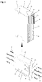
- FIG 1 is a fastening device 1 for fixing a post profile 2 of a post and beam construction for facades, conservatories, skylights and the like. Shown.
- the fastening device 1 has a base part 3 that can be fastened to the ground or a lower part and a holding part 4 that can be adjusted relative to the base part 3 and fixed in a selected position for fastening the post profile.
- the holding part 4 is designed as a slide-in part to be accommodated inside the post profile 2 .
- the post profile 2 is designed as a hollow profile with two mutually parallel side walls 5 and 6, two inner and outer end walls 7 and 8 perpendicular to the side walls 4 and 5, and an interior space 9 designed as a cavity.
- the outer end wall 8 pointing to the outside of the mullion-transom construction contains an outwardly protruding web 10 with a receiving channel 11 open to the outside for fastening screws or other fastening elements, through the holding profiles (not shown here) or a holding structure for holding glass panes or others Facade elements on the outer end wall 8 can be attached.
- receiving grooves 12 running in the longitudinal direction of the post profile 2 are also provided on the outer end wall 8 for receiving an inner seal or a sealing piece.
- the post profile 2 is designed in the form of a metal profile tube that is produced, for example, by extrusion, and that can be made of steel or aluminum. However, it can also be produced as a welded construction from a suitably bent and welded metal sheet, as a wooden or plastic construction or the like.
- the outwardly protruding web 10 on the outer end wall 8, which is directed towards the outside and is used for fastening panes of glass or other facade elements, has a receiving channel 11 designed as a screw channel in the exemplary embodiment shown. Fastening screws provided with a cutting thread, for example, can be screwed into the receiving channel 11 for fastening holding profiles or other supporting or facade elements.
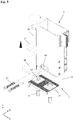
- the post profile 2 in the lower part of the outer end wall 8 directed to the outside has a recessed, flattened area 13 without a web 10 projecting outwards and without receiving grooves 12 .
- Bores 14 for fastening the in figure 3 provided holding profile 4 shown in more detail.
- the retaining part 4 designed as an insert profile has a block-shaped insert body 15 adapted to the inner contour of the post profile 2 with a U-shaped cross section and lower contact surfaces 16 for contacting a lower end face of the post profile 2 .
- the holding part 4 contains two downwardly projecting parallel legs 17 and a downwardly open slot 18 arranged between them for receiving the base part 3 .
- In the two legs 17 of the holding part 4 there are two rectangular openings 19 running in the longitudinal direction of the slot 18 and open towards the end faces of the holding part 4 for inserting a figure 4 shown fork-shaped lifting element 20 of an actuating device 21 explained in more detail below is provided.
- Bores 22 for screws 23 are also arranged on the end faces of the two legs 17 .
- lateral through-openings 24 are also provided for fastening elements 25, which are preferably designed as self-drilling screws.
- the retaining profile 4 is inserted with its slide-in body 15 from below into the post profile 2 until the lateral lower webs 16 come to rest on the lower face of the post profile 2 .
- the screws 23, which are screwed through the holes 14 in the threaded holes 22 on the end faces of the two legs 17 of the holding profile 4 the holding profile 4 is fixed inside the post profile 2.
- Out of figure 1 shows that also in the inner end wall 7 of the post profile 2 with the openings 19 in the holding profile 4 aligned openings 26 for inserting the fork-shaped lifting element 20 are provided.
- the openings 26 are at one corresponding recess at the lower end of the inner end wall 7 of the post profile 2 is arranged.
- the adjusting device 21 used only for the alignment of the post profile 2 can be dismantled and reused after the post profile 2 has been attached.
- it contains an adjusting screw 28 which is arranged in a thread 27 of the lifting element 20 and whose lower end can be supported on a shim 29 .
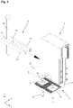
- the angular base part 3 that can be seen particularly well has a horizontal base plate 30 and a holding web 31 perpendicular thereto for introduction into the slot 18 of the holding profile 4 .
- the holding web 31 has a thickness adapted to the width of the slot 18, so that the holding profile 4 is guided on the holding web 31 in a horizontally and vertically displaceable manner.
- a corrugation 32 is provided on the upper side of the base plate 25 .
- the base parts 3 can be fastened to the base or a lower part via elongated holes in the base plate 30, threaded pins 33 with a nut 34 and retaining plates 35 which have counter-corrugation 36 matching the corrugation 32 on their underside.
- the post profile 2 with the holding part 4 fastened therein is placed on the vertical holding web 31 of the angled bottom part 3 .
- corresponding elongated holes are provided in the base plate 30 of the base part 3 so that the base part 3 can be displaced and aligned relative to the threaded pins 33 by loosening the nuts. This allows the position of the post profile 2 to be adjusted in the X-axis.
- the fork-shaped lifting element 20 of the adjusting device 21 is inserted together with the adjusting screw 28 into the post profile 2 in such a way that the two legs 37 of the fork-shaped lifting element 20 pass through the in figure 1 recognizable openings 26 in the post profile 2 in the in figure 2 shown rectangular openings 19 of the holding part 4 engage.
- the adjusting screw 28 can then be screwed in until its lower end is rotated to rest against the base plate 29 .
- the post profile 2 can then be raised and thus the position of the post profile 2 in the Z-axis can be adjusted.
- the self-tapping screws 25 can be screwed into the holes 24 and thus the post profile 2 are attached.
- the adjusting device 21 can then be removed and reused.
Landscapes
- Engineering & Computer Science (AREA)
- Architecture (AREA)
- Physics & Mathematics (AREA)
- Electromagnetism (AREA)
- Civil Engineering (AREA)
- Structural Engineering (AREA)
- Load-Bearing And Curtain Walls (AREA)
- Joining Of Building Structures In Genera (AREA)
Abstract
Description
- Die Erfindung betrifft eine Befestigungseinrichtung und ein Verfahren zur Ausrichtung und Fixierung eines Pfostenprofils einer Pfosten-Riegel-Konstruktion.
- Aus der
EP 0 428 962 A2 ist eine gattungsgemäße Befestigungseinrichtung zur Ausrichtung und Fixierung eines Pfostenprofils bekannt. Diese weist eine mittels Befestigungsschrauben am Untergrund fixierbare Bodenplatte mit vertikalen Führungsbahnen und einen über die Führungsbahnen an der Bodenplatte geführten Aufnahmeschuh zur Befestigung des Pfostenprofils auf. Die Bodenplatte enthält vertikal nach oben ragende Stege, zwischen denen die Führungsbahnen zur Führung des Aufnahmeschuhs begrenzt werden. Der in einem Vertikalschnitt U-förmige Aufnahmeschuh ist mit Seitenwangen ausgestattet, die an ihrer Außenseite Führungsstücke zum Eingriff in die Führungsbahnen der Bodenplatte aufweisen. Zwischen die Seitenwangen des Aufnahmeschuhs wird das Pfostenprofil eingesetzt und durch zwei zueinander parallele Gewindebolzen fixiert. Die Bodenplatte ist so gestaltet, dass sie gegenüber ihren Befestigungsschrauben in ihrer Längsrichtung und in einer quer dazu laufenden Richtung verstellbar ist. Zur Höhenverstellung des Aufnahmeschuhs gegenüber der Bodenplatte wird eine Stellschraube verwendet, die sich mit ihrem Kopf an der Bodenplatte abstützt und sich mit ihrem Schaft durch eine Bohrung im Boden des Aufnahmeschuhs und in einer mit dem Boden einstückigen Leiste erstreckt. Dadurch kann ein Pfostenprofil in drei zueinander orthogonalen Achsen ausgerichtet und fixiert werden. Allerdings ist die Befestigungseinrichtung relativ aufwändig und erfordert einen hohen konstruktiven und fertigungstechnischen Aufwand. - Aufgabe der Erfindung ist es, eine Befestigungseinrichtung und ein Verfahren zur Ausrichtung und Fixierung eines Pfostenprofils einer Pfosten-Riegel-Konstruktion zu schaffen, die eine einfache und kostengünstige Befestigung eines Pfostenprofils mit hoher Positioniergenauigkeit ermöglichen.
- Diese Aufgabe wird durch eine Befestigungseinrichtung mit den Merkmalen des Anspruchs 1 und durch ein Verfahren mit den Merkmalen des Anspruchs 12 gelöst. Zweckmäßige Weiterbildungen und vorteilhafte Ausführungsformen der Erfindung sind Gegenstand der Unteransprüche.
- Die erfindungsgemäße Befestigungseinrichtung zur Ausrichtung und Fixierung eines Pfostenprofils einer Pfosten-Riegel-Konstruktion enthält ein Bodenteil und einem relativ zum Bodenteil in der Höhe verstellbares und in einer ausgewählten Stellung fixierbares Halteteil zur Befestigung des Pfostenprofils. Das Halteteil ist als Einschubteil zur Aufnahme in einem Innenraum des Pfostenprofils ausgebildet und über Befestigungselemente fest mit dem Bodenteil verbindbar. Bei den Befestigungselementen kann es sich z.B. um selbstbohrende Schrauben handeln, durch die das Pfostenprofil mit dem darin angeordneten Halteteil in einer ausgewählten Stellung gegenüber dem Bodenteil fixiert wird. Durch das als Einschubteil ausgebildete Halteteil und das zugehörige Bodenteil kann das Pfostenprofil in drei zueinander rechtwinkligen Achsen ausgerichtet und stabil montiert werden.
- In einer besonders zweckmäßigen Ausführung weist das Halteteil einen an die Innenkontur des Pfostenprofils angepassten Einschubkörper und untere Anlageflächen zur Anlage einer unteren Stirnseite des Pfostenprofils auf. Dadurch kann eine genau und stabile Verbindung zwischen dem Pfostenprofil und dem Halteteil erreicht werden. Das Halteteil kann in einer vorteilhaften Ausführung zwei nach unten ragende parallele Schenkel und einen dazwischen angeordneten, nach unten offenen Schlitz zur Aufnahme eines Haltestegs des Bodenteils enthalten. Dadurch kann das Pfostenprofil gegenüber dem Bodenteil in einer Vertikalachse und einer dazu senkrechten Horizontalachse verschiebbar geführt sein.
- Das Bodenteil kann z.B. winkelförmig mit einer auf dem Untergrund befestigbaren Bodenplatte und einem von der Bodenplatte rechtwinklig vorstehenden Haltesteg ausgebildet sein. Das Bodenteil kann aber auch eine andere Form aufweisen.
- Das Halteteil ist zweckmäßigerweise in einer Vertikalachse (Z-Achse) und einer dazu rechtwinkligen Horizontalachse (Y-Achse) verstellbar an den Bodenteil geführt. Das Halteteil kann über Schrauben oder dgl. im Innenraum des Pfostenprofils befestigt sein. Das Halteteil kann außerdem seitliche Durchgangsbohrungen für die Befestigungselemente zur Befestigung am Bodenteil aufweisen.
- In einer für die Ausrichtung und Montage besonders vorteilhaften Ausgestaltung sind in dem Pfostenprofil und dem im Pfostenprofil befestigten Halteteil zueinander korrespondierende Öffnungen zum Einstecken eines Hubelements einer Stelleinrichtung angeordnet. Das Hubelement kann zwei zueinander parallele Schenkel zum Eingriff in die Öffnungen des Halteteils und eine Gewindebohrung zur Aufnahme einer Stellschraube enthalten.
- Die Erfindung betrifft außerdem ein Verfahren zur Ausrichtung und Fixierung eines Pfostenprofils einer Pfosten-Riegel-Konstruktion mit einer vorstehend beschriebenen Befestigungseinrichtung, Das Verfahren zeichnet sich dadurch aus, dass die Position des Pfostenprofils durch ein in das Halteteil einsteckbares und nach der Befestigung wieder demontierbares Hubelement einer Stelleinrichtung einstellbar ist. Die Stelleinrichtung muss also nicht an der Pfostenkonstruktion verbleiben, sondern kann nach der Befestigung des Pfostenprofils demontiert und wiederverwendet werden.
- Weitere Besonderheiten und Vorzüge der Erfindung ergeben sich aus der folgenden Beschreibung eines bevorzugten Ausführungsbeispiels anhand der Zeichnung. Es zeigen:
- Figur 1
- ein Ausführungsbeispiel einer Befestigungseinrichtung mit einem Bodenteil und einem im Pfostenprofil angeordneten Halteteil in einer ersten Perspektive;
- Figur 2
- das Pfostenprofil und das Halteteil der in
Figur 1 gezeigten Befestigungseinrichtung in einer Perspektivansicht; - Figur 3
- das Pfostenprofil und das Bodenteil der in
Figur 1 gezeigten Befestigungseinrichtung in einer Perspektivansicht; - Figur 4
- eine Perspektivansicht der in
Figur 1 gezeigte Befestigungseinrichtung mit einer Stelleinrichtung vor der Montage und - Figur 5
- eine Perspektivansicht der in
Figur 1 gezeigte Befestigungseinrichtung mit einer Stelleinrichtung während der Montage. - In
Figur 1 ist eine Befestigungseinrichtung 1 zur Fixierung eines Pfostenprofils 2 einer Pfosten-Riegel-Konstruktion für Fassaden, Wintergärten, Lichtdächer und dgl. gezeigt. Die Befestigungseinrichtung 1 weist eine am Boden oder einem Unterteil befestigbares Bodenteil 3 und ein relativ zum Bodenteil 3 verstellbares und in einer ausgewählten Stellung fixierbares Halteteil 4 zur Befestigung des Pfostenprofils auf. Das Halteteil 4 ist als Einschubteil zur Aufnahme im Inneren des Pfostenprofils 2 ausgebildet. - Das Pfostenprofil 2 ist bei gezeigten Ausführung als Hohlprofil mit zwei zueinander parallelen Seitenwänden 5 und 6, zwei zu den Seitenwänden 4 und 5 rechtwinkligen inneren und äußeren Stirnwänden 7 und 8 und einem als Hohlraum ausgebildeten Innenraum 9 ausgeführt. Die zur Außenseite der Pfosten-Riegel-Konstruktion weisende äußere Stirnwand 8 enthält einen nach außen vorstehenden Steg 10 mit einem und zur Außenseite hin offenen Aufnahmekanal 11 für Befestigungsschrauben oder andere Befestigungselemente, durch die hier nicht dargestellte Halteprofile oder eine Haltekonstruktion zur Halterung von Glasscheiben oder anderen Fassadenelementen an der äußeren Stirnwand 8 befestigt werden können. Rechts und links des Stegs 10 sind an der äußeren Stirnwand 8 außerdem in Längsrichtung des Pfostenprofils 2 verlaufende Aufnahmenuten 12 zur Aufnahme einer Innendichtung oder eines Dichtstücks vorgesehen.
- Das Pfostenprofil 2 ist im dargestellten Ausführungsbeispiel in Form eines z.B. im Strangpressverfahren hergestellten Metallprofilrohrs ausgeführt, das aus Stahl oder Aluminium bestehen kann. Es kann aber auch als Schweißkonstruktion aus einem entsprechend gebogenen und verschweißten Metallblech, als Holz- bzw. Kunststoffkonstruktion oder dgl. hergestellt sein. Der nach außen vorstehende Steg 10 an der zur Außenseite gerichteten und zur Befestigung von Glasscheiben oder anderer Fassadenelemente dienenden äußeren Stirnwand 8 weist bei dem gezeigten Ausführungsbeispiel einen als Schraubkanal ausgeführten Aufnahmekanal 11 auf. In den Aufnahmekanal 11 können z.B. mit einem Schneidgewinde versehene Befestigungsschrauben zur Befestigung von Halteprofilen oder weiteren Trag- oder Fassadenelementen eingeschraubt werden.
- Wie aus
Figur 2 hervorgeht, weist das Pfostenprofil 2 im unteren Teil der zur Außenseite gerichteten äußeren Stirnwand 8 einen zurückversetzen abgeflachten Bereich 13 ohne nach außen vorstehenden Steg 10 und ohne Aufnahmenuten 12 auf. In dem abgeflachten Bereich 13, der z.B. durch Abfräsen des Stegs 10 und der die Aufnahmenuten 12 begrenzenden Seitenstege hergestellt werden kann, sind Bohrungen 14 zur Befestigung des inFigur 3 näher dargestellten Halteprofils 4 vorgesehen. - In
Figur 3 ist erkennbar, dass das als Einschubprofil ausgebildete Halteteil 4 einen an die Innenkontur des Pfostenprofils 2 angepassten blockförmigen Einschubkörper 15 mit einem U-förmigen Querschnitt und untere Anlageflächen 16 zur Anlage einer unteren Stirnseite des Pfostenprofils 2 aufweist. Das Halteteil 4 enthält zwei nach unten ragende parallele Schenkel 17 und einen dazwischen angeordneten, nach unten offenen Schlitz 18 zur Aufnahme des Bodenteils 3. Die Anlageflächen 16 sind an nach außen vorstehenden Stegen am unteren Ende der Außenseiten der beiden Schenkel 17 vorgesehen. In den beiden Schenkeln 17 des Halteteils 4 sind zwei in Längsrichtung des Schlitzes 18 verlaufende und zu den Stirnseiten des Halteteils 4 hin offene rechteckige Öffnungen 19 zum Einstecken eines inFigur 4 gezeigten gabelförmigen Hubelements 20 einer im Folgenden noch näher erläuterten Stelleinrichtung 21 vorgesehen. An den Stirnseiten der beiden Schenkel 17 sind außerdem Bohrungen 22 für Schrauben 23 angeordnet. In den beiden Seitenflächen der Schenkel 17 des Halteprofils 4 sind ferner seitliche Durchgangsöffnungen 24 für vorzugsweise als selbstbohrende Schrauben ausgebildete Befestigungselemente 25 vorgesehen. - Das Halteprofil 4 wird mit seinem Einschubkörper 15 von unten in das Pfostenprofil 2 eingesetzt, bis die seitlichen unteren Stege 16 zur Anlage an der unteren Stirnseite des Pfostenprofils 2 gelangen. Über die Schrauben 23, die durch die Bohrungen 14 in die Gewindebohrungen 22 an den Stirnseiten der beiden Schenkel 17 des Halteprofils 4 eingeschraubt werden, wird das Halteprofil 4 im Inneren des Pfostenprofils 2 fixiert.
- Aus
Figur 1 geht hervor, dass auch in der inneren Stirnwand 7 des Pfostenprofils 2 mit den Öffnungen 19 im Halteprofil 4 fluchtende Öffnungen 26 zum Einstecken des gabelförmigen Hubelements 20 vorgesehen sind. Bei der gezeigten Ausführung sind die Öffnungen 26 an einer entsprechenden Aussparung am unteren Ende der inneren Stirnwand 7 des Pfostenprofils 2 angeordnet. Die lediglich für die Ausrichtung des Pfostenprofils 2 verwendete Stelleinrichtung 21 kann nach der Befestigung des Pfostenprofils 2 demontiert und wiederverwendet werden. Sie enthält neben dem gabelförmigen Hubelement 20 eine in einem Gewinde 27 des Hubelements 20 angeordnete Stellschraube 28, deren unteres Ende auf einer Unterlegplatte 29 abgestützt werden kann. - Das in
Figur 3 besonders gut erkennbare winkelförmige Bodenteil 3 weist eine horizontale Bodenplatte 30 und einen dazu rechtwinkligen Haltesteg 31 zur Einführung in den Schlitz 18 des Halteprofils 4 auf. Der Haltesteg 31 hat eine an die Breite des Schlitzes 18 angepasste Dicke, so dass das Halteprofil 4 horizontal und vertikal verschiebbar auf den Haltesteg 31 geführt ist. Auf der Oberseite der Bodenplatte 25 ist eine Riffelung 32 vorgesehen. Über Langlöcher in der Bodenplatte 30, Gewindestifte 33 mit einer Mutter 34 und Halteplatten 35, die an ihrer Unterseite eine zu der Riffelung 32 passende Gegenriffelung 36 aufweisen, sind die Bodenteile 3 auf dem Boden oder einem Unterteil befestigbar. - Wie aus den
Figuren 4 und5 hervorgeht, wird das Pfostenprofil 2 mit dem darin befestigten Halteteil 4 auf den vertikalen Haltesteg 31 des winkelförmigen Bodenteils 3 aufgesetzt. Wie bereits vorstehend beschrieben, sind in der Bodenplatte 30 des Bodenteils 3 entsprechende Langlöcher vorgesehen, so dass das Bodenteil 3 durch Lockern der Muttern relativ zu den kann Gewindestiften 33 verschoben und ausgerichtet werden kann. Dadurch kann die Position des Pfostenprofils 2 in der X-Achse eingestellt werden. Nach dem Aufsetzen des Pfostenprofils 2 auf den Haltesteg 31 des Bodenteils 3 wird das gabelförmige Hubelement 20 der Stelleinrichtung 21 zusammen mit der Stellschraube 28 so in das Pfostenprofil 2 eingesetzt, dass die beiden Schenkel 37 des gabelförmigen Hubelement 20 durch die inFigur 1 erkennbaren Öffnungen 26 im Pfostenprofil 2 in die inFigur 2 gezeigten rechteckigen Öffnungen 19 des Halteteils 4 eingreifen. Durch Verschiebung des Pfostenprofils 2 relativ zum gabelförmigen Hubelement 20 kann die Position des Pfostenprofils 2 in der Y-Achse eingestellt werden. Anschließend kann die Stellschraube 28 so weit eingedreht werden, bis deren unteres Ende zur Anlage an der Unterlegplatte 29 gedreht werden. Durch weitere Drehung der Stellschraube 28 kann dann das Pfostenprofil 2 angehoben und somit die Position des Pfostenprofils 2 in der Z-Achse eingestellt werden. Sobald das Pfostenprofil 2 die gewünschte Position in der X-, Y- und Z-Achse einnimmt, können die selbstschneidenden Schrauben 25 in die Bohrungen 24 eingeschraubt und somit das Pfostenprofil 2 befestigt werden. Anschließend kann die Stelleinrichtung 21 entfernt und wiederverwendet werden. -
- 1
- Befestigungseinrichtung
- 2
- Pfostenprofil
- 3
- Bodenteil
- 4
- Halteteil
- 5
- Seitenwand
- 6
- Seitenwand
- 7
- Innere Stirnwand
- 8
- Äußere Stirnwand
- 9
- Hohlraum
- 10
- Steg
- 11
- Aufnahmekanal
- 12
- Aufnahmenut
- 13
- Abgeflachter Bereich
- 14
- Bohrung
- 15
- Einschubkörper
- 16
- Anlagefläche
- 17
- Schenkel
- 18
- Schlitz
- 19
- Öffnung
- 20
- Hubelement
- 21
- Stelleinrichtung
- 22
- Bohrung
- 23
- Schraube
- 24
- Durchgangsbohrung
- 25
- Befestigungselement
- 26
- Öffnung
- 27
- Gewinde
- 28
- Stellschraube
- 29
- Unterlegplatte
- 30
- Bodenplatte
- 31
- Haltesteg
- 32
- Riffelung
- 33
- Gewindestift
- 34
- Mutter
- 35
- Halteplatte
- 36
- Gegenriffelung
- 37
- Steg
Claims (12)
- Befestigungseinrichtung (1) zur Ausrichtung und Fixierung eines Pfostenprofils (2) einer Pfosten-Riegel-Konstruktion, mit einem Bodenteil (3) und einem relativ zum Bodenteil (3) in der Höhe verstellbaren und in einer ausgewählten Stellung fixierbaren Halteteil (4) zur Befestigung des Pfostenprofils (2), dadurch gekennzeichnet, dass das Halteteil (4) als Einschubteil zur Aufnahme in einem Innenraum (9) des Pfostenprofils (2) ausgebildet und über Befestigungselemente (25) fest mit dem Bodenteil (3) verbindbar ist.
- Befestigungseinrichtung (1) nach Anspruch 1, dadurch gekennzeichnet, dass das Halteteil (4) einen an die Innenkontur des Pfostenprofils (2) angepassten Einschubkörper (15) und untere Anlageflächen (16) zur Anlage einer unteren Stirnseite des Pfostenprofils (2) aufweist.
- Befestigungseinrichtung (1) nach Anspruch 1 oder 2, dadurch gekennzeichnet, dass das Halteteil (4) zwei nach unten ragende parallele Schenkel (17) und einen dazwischen angeordneten, nach unten offenen Schlitz (18) zur Aufnahme eines Haltestegs (31) des Bodenteils (3) aufweist.
- Befestigungseinrichtung (1) nach Anspruch 3, dadurch gekennzeichnet, dass der Haltesteg (31) eine an die Breite des Schlitzes (18) angepasste Dicke aufweist.
- Befestigungseinrichtung (1) nach Anspruch 3 oder 4, dadurch gekennzeichnet, dass das Bodenteil (3) eine Bodenplatte (30) enthält, von welcher der Haltesteg (31) rechtwinklig vorsteht.
- Befestigungseinrichtung (1) nach einem der Ansprüche 1 bis 5, dadurch gekennzeichnet, dass das Halteteil (4) über Schrauben (23) im Innenraum (9) des Pfostenprofils (2) befestigt ist.
- Befestigungseinrichtung (1) nach einem der Ansprüche 1 bis 6, dadurch gekennzeichnet, dass das Halteteil (4) seitliche Durchgangsöffnungen (24) für die Befestigungselemente (25) zur Befestigung am Bodenteil (3) enthält.
- Befestigungseinrichtung (1) nach einem der Ansprüche 1 bis 7, dadurch gekennzeichnet, dass das Halteteil (4) in einer Vertikalachse (Z-Achse) und einer dazu rechtwinkligen Horizontalachse (Y-Achse) verstellbar an den Bodenteil (3) geführt ist.
- Befestigungseinrichtung (1) nach einem der Ansprüche 1 bis 8, dadurch gekennzeichnet, dass in dem Pfostenprofil (1) und dem im Pfostenprofil (1) befestigten Halteteil (4) zueinander korrespondierende Öffnungen (19, 26) zum Einstecken eines Hubelements (20) einer Stelleinrichtung (21) angeordnet sind.
- Befestigungseinrichtung (1) nach Anspruch 9, dadurch gekennzeichnet, dass das Hubelement (20) zwei parallele Schenkel (37) und ein Gewinde (27) zur Aufnahme einer Stellschraube (28) enthält.
- Befestigungseinrichtung (1) nach einem der Ansprüche 1 bis 10, dadurch gekennzeichnet, dass die Befestigungselemente (25) als selbstbohrende Schrauben ausgebildet sind.
- Verfahren zur Ausrichtung und Fixierung eines Pfostenprofils (2) einer Pfosten-Riegel-Konstruktion mit einer Befestigungseinrichtung (1) nach einem der Ansprüche 1 bis 11, dadurch gekennzeichnet, dass die Position des Pfostenprofils (2) durch ein in das Halteteil (4) einsteckbares und nach der Befestigung wieder demontierbares Hubelement (20) einer Stelleinrichtung (21) einstellbar ist.
Applications Claiming Priority (1)
| Application Number | Priority Date | Filing Date | Title |
|---|---|---|---|
| DE102020132669.6A DE102020132669A1 (de) | 2020-12-08 | 2020-12-08 | Befestigungseinrichtung und Verfahren zur Ausrichtung und Fixierung eines Pfostenprofils einer Pfosten-Riegel-Konstruktion |
Publications (2)
| Publication Number | Publication Date |
|---|---|
| EP4012131A1 true EP4012131A1 (de) | 2022-06-15 |
| EP4012131B1 EP4012131B1 (de) | 2025-04-09 |
Family
ID=78592565
Family Applications (1)
| Application Number | Title | Priority Date | Filing Date |
|---|---|---|---|
| EP21207046.0A Active EP4012131B1 (de) | 2020-12-08 | 2021-11-09 | Befestigungseinrichtung und verfahren zur ausrichtung und fixierung eines pfostenprofils einer pfosten-riegel-konstruktion |
Country Status (2)
| Country | Link |
|---|---|
| EP (1) | EP4012131B1 (de) |
| DE (1) | DE102020132669A1 (de) |
Families Citing this family (1)
| Publication number | Priority date | Publication date | Assignee | Title |
|---|---|---|---|---|
| CN116497993A (zh) * | 2023-06-05 | 2023-07-28 | 中建八局第三建设有限公司 | 一种弧形幕墙施工方法 |
Citations (3)
| Publication number | Priority date | Publication date | Assignee | Title |
|---|---|---|---|---|
| EP0428962A2 (de) | 1989-11-24 | 1991-05-29 | SCHÜCO International KG | Fassadenfuss für ein Pfostenprofil |
| JPH11241440A (ja) * | 1998-02-23 | 1999-09-07 | Matsushita Electric Works Ltd | 支柱固定構造 |
| DE29919320U1 (de) * | 1999-11-03 | 1999-12-30 | Heidemann Modular Space Systems Ltd., North Yorkshire | Rahmensystem für Bauten |
-
2020
- 2020-12-08 DE DE102020132669.6A patent/DE102020132669A1/de not_active Withdrawn
-
2021
- 2021-11-09 EP EP21207046.0A patent/EP4012131B1/de active Active
Patent Citations (3)
| Publication number | Priority date | Publication date | Assignee | Title |
|---|---|---|---|---|
| EP0428962A2 (de) | 1989-11-24 | 1991-05-29 | SCHÜCO International KG | Fassadenfuss für ein Pfostenprofil |
| JPH11241440A (ja) * | 1998-02-23 | 1999-09-07 | Matsushita Electric Works Ltd | 支柱固定構造 |
| DE29919320U1 (de) * | 1999-11-03 | 1999-12-30 | Heidemann Modular Space Systems Ltd., North Yorkshire | Rahmensystem für Bauten |
Also Published As
| Publication number | Publication date |
|---|---|
| EP4012131B1 (de) | 2025-04-09 |
| DE102020132669A1 (de) | 2022-06-09 |
Similar Documents
| Publication | Publication Date | Title |
|---|---|---|
| DE2618442C2 (de) | Stütze für ein Geländer oder dergleichen | |
| EP0945577A2 (de) | Vorrichtung zum Abstützen von Fenster- oder Türrahmen an der Begrenzung einer Wandöffnung | |
| DE202015104250U1 (de) | Pfosten-Riegel-Verbindung | |
| EP4012131A1 (de) | Befestigungseinrichtung und verfahren zur ausrichtung und fixierung eines pfostenprofils einer pfosten-riegel-konstruktion | |
| EP0972891A2 (de) | Vorrichtung für die Befestigung von Glasscheiben an Gebäudefassaden | |
| EP1098046B1 (de) | Verkleidungssystem für Fassaden und Dächer von Bauwerken | |
| CH695904A5 (de) | Vorrichtung zur Aufnahme eines Lauforgans. | |
| DE19623870C1 (de) | Vorrichtung zum lösbaren Verbinden von Profilstäben | |
| EP1078135A1 (de) | Fassadensystem für die verkleidung eines bauwerks | |
| EP1602836B1 (de) | Gratleiste für Massivholz | |
| EP0814215B1 (de) | Fassadensystem, sowie Befestigungssystem | |
| EP1342861B1 (de) | Befestigungsvorrichtung | |
| DE102015118360A1 (de) | Halterung für plattenelemente von brüstungen, geländern und dergleichen | |
| DE3001026A1 (de) | Vorrichtung zur befestigung eines beschlages in einem fluegelprofil fuer fenster oder tueren | |
| DE3001025A1 (de) | Vorrichtung zur befestigung eines beschlages in einem fluegelprofil fuer fenster oder tueren | |
| DE102020106891B4 (de) | T-Verbindung zwischen einem Pfosten- und Riegelprofil und Pfosten-Riegel-Konstruktion mit einer derartigen T-Verbindung | |
| DE102009026105B4 (de) | System zum Verbinden von Pfosten und Riegeln und Verwendung | |
| DE202024101757U1 (de) | Tragschiene | |
| DE4318615A1 (de) | Vorrichtung und Verfahren zum stirnseitigen Verbinden eines profilierten Bauelementes, insbesondere eines Rohres, mit einem anderen Element | |
| EP1323933B1 (de) | Halterung für eine langgestreckte Profilschiene aus einem nach unten hin offenen C-Profil | |
| EP0379656A1 (de) | Verankerungsvorrichtung für Fenster- und Türrahmen | |
| DE20000552U1 (de) | Profilschienensystem | |
| DE19741663A1 (de) | Traggestell für Förderer, insbesondere für Rollenbahnen | |
| EP4411085A1 (de) | Anordnung mit in einer trockenbauwand angeordneten einbauelementen und befestigungsverfahren hierfür | |
| DE4421107A1 (de) | Vorrichtung zur Verbindung von Profilleisten |
Legal Events
| Date | Code | Title | Description |
|---|---|---|---|
| PUAI | Public reference made under article 153(3) epc to a published international application that has entered the european phase |
Free format text: ORIGINAL CODE: 0009012 |
|
| STAA | Information on the status of an ep patent application or granted ep patent |
Free format text: STATUS: THE APPLICATION HAS BEEN PUBLISHED |
|
| AK | Designated contracting states |
Kind code of ref document: A1 Designated state(s): AL AT BE BG CH CY CZ DE DK EE ES FI FR GB GR HR HU IE IS IT LI LT LU LV MC MK MT NL NO PL PT RO RS SE SI SK SM TR |
|
| STAA | Information on the status of an ep patent application or granted ep patent |
Free format text: STATUS: REQUEST FOR EXAMINATION WAS MADE |
|
| 17P | Request for examination filed |
Effective date: 20221215 |
|
| RBV | Designated contracting states (corrected) |
Designated state(s): AL AT BE BG CH CY CZ DE DK EE ES FI FR GB GR HR HU IE IS IT LI LT LU LV MC MK MT NL NO PL PT RO RS SE SI SK SM TR |
|
| GRAP | Despatch of communication of intention to grant a patent |
Free format text: ORIGINAL CODE: EPIDOSNIGR1 |
|
| STAA | Information on the status of an ep patent application or granted ep patent |
Free format text: STATUS: GRANT OF PATENT IS INTENDED |
|
| INTG | Intention to grant announced |
Effective date: 20250103 |
|
| GRAS | Grant fee paid |
Free format text: ORIGINAL CODE: EPIDOSNIGR3 |
|
| GRAA | (expected) grant |
Free format text: ORIGINAL CODE: 0009210 |
|
| STAA | Information on the status of an ep patent application or granted ep patent |
Free format text: STATUS: THE PATENT HAS BEEN GRANTED |
|
| AK | Designated contracting states |
Kind code of ref document: B1 Designated state(s): AL AT BE BG CH CY CZ DE DK EE ES FI FR GB GR HR HU IE IS IT LI LT LU LV MC MK MT NL NO PL PT RO RS SE SI SK SM TR |
|
| REG | Reference to a national code |
Ref country code: GB Ref legal event code: FG4D Free format text: NOT ENGLISH |
|
| REG | Reference to a national code |
Ref country code: CH Ref legal event code: EP |
|
| P01 | Opt-out of the competence of the unified patent court (upc) registered |
Free format text: CASE NUMBER: APP_13072/2025 Effective date: 20250317 |
|
| REG | Reference to a national code |
Ref country code: DE Ref legal event code: R096 Ref document number: 502021007152 Country of ref document: DE |
|
| REG | Reference to a national code |
Ref country code: IE Ref legal event code: FG4D Free format text: LANGUAGE OF EP DOCUMENT: GERMAN |
|
| REG | Reference to a national code |
Ref country code: NL Ref legal event code: MP Effective date: 20250409 |
|
| PG25 | Lapsed in a contracting state [announced via postgrant information from national office to epo] |
Ref country code: NL Free format text: LAPSE BECAUSE OF FAILURE TO SUBMIT A TRANSLATION OF THE DESCRIPTION OR TO PAY THE FEE WITHIN THE PRESCRIBED TIME-LIMIT Effective date: 20250409 |
|
| PG25 | Lapsed in a contracting state [announced via postgrant information from national office to epo] |
Ref country code: ES Free format text: LAPSE BECAUSE OF FAILURE TO SUBMIT A TRANSLATION OF THE DESCRIPTION OR TO PAY THE FEE WITHIN THE PRESCRIBED TIME-LIMIT Effective date: 20250409 Ref country code: FI Free format text: LAPSE BECAUSE OF FAILURE TO SUBMIT A TRANSLATION OF THE DESCRIPTION OR TO PAY THE FEE WITHIN THE PRESCRIBED TIME-LIMIT Effective date: 20250409 Ref country code: PT Free format text: LAPSE BECAUSE OF FAILURE TO SUBMIT A TRANSLATION OF THE DESCRIPTION OR TO PAY THE FEE WITHIN THE PRESCRIBED TIME-LIMIT Effective date: 20250811 |
|
| REG | Reference to a national code |
Ref country code: LT Ref legal event code: MG9D |
|
| PG25 | Lapsed in a contracting state [announced via postgrant information from national office to epo] |
Ref country code: GR Free format text: LAPSE BECAUSE OF FAILURE TO SUBMIT A TRANSLATION OF THE DESCRIPTION OR TO PAY THE FEE WITHIN THE PRESCRIBED TIME-LIMIT Effective date: 20250710 Ref country code: NO Free format text: LAPSE BECAUSE OF FAILURE TO SUBMIT A TRANSLATION OF THE DESCRIPTION OR TO PAY THE FEE WITHIN THE PRESCRIBED TIME-LIMIT Effective date: 20250709 |
|
| PG25 | Lapsed in a contracting state [announced via postgrant information from national office to epo] |
Ref country code: PL Free format text: LAPSE BECAUSE OF FAILURE TO SUBMIT A TRANSLATION OF THE DESCRIPTION OR TO PAY THE FEE WITHIN THE PRESCRIBED TIME-LIMIT Effective date: 20250409 |
|
| PG25 | Lapsed in a contracting state [announced via postgrant information from national office to epo] |
Ref country code: BG Free format text: LAPSE BECAUSE OF FAILURE TO SUBMIT A TRANSLATION OF THE DESCRIPTION OR TO PAY THE FEE WITHIN THE PRESCRIBED TIME-LIMIT Effective date: 20250409 |
|
| PG25 | Lapsed in a contracting state [announced via postgrant information from national office to epo] |
Ref country code: HR Free format text: LAPSE BECAUSE OF FAILURE TO SUBMIT A TRANSLATION OF THE DESCRIPTION OR TO PAY THE FEE WITHIN THE PRESCRIBED TIME-LIMIT Effective date: 20250409 |
|
| PG25 | Lapsed in a contracting state [announced via postgrant information from national office to epo] |
Ref country code: RS Free format text: LAPSE BECAUSE OF FAILURE TO SUBMIT A TRANSLATION OF THE DESCRIPTION OR TO PAY THE FEE WITHIN THE PRESCRIBED TIME-LIMIT Effective date: 20250709 |
|
| PG25 | Lapsed in a contracting state [announced via postgrant information from national office to epo] |
Ref country code: IS Free format text: LAPSE BECAUSE OF FAILURE TO SUBMIT A TRANSLATION OF THE DESCRIPTION OR TO PAY THE FEE WITHIN THE PRESCRIBED TIME-LIMIT Effective date: 20250809 |
|
| PG25 | Lapsed in a contracting state [announced via postgrant information from national office to epo] |
Ref country code: LV Free format text: LAPSE BECAUSE OF FAILURE TO SUBMIT A TRANSLATION OF THE DESCRIPTION OR TO PAY THE FEE WITHIN THE PRESCRIBED TIME-LIMIT Effective date: 20250409 |
|
| REG | Reference to a national code |
Ref country code: CH Ref legal event code: U11 Free format text: ST27 STATUS EVENT CODE: U-0-0-U10-U11 (AS PROVIDED BY THE NATIONAL OFFICE) Effective date: 20251201 |
|
| PGFP | Annual fee paid to national office [announced via postgrant information from national office to epo] |
Ref country code: DE Payment date: 20251211 Year of fee payment: 5 |
|
| REG | Reference to a national code |
Ref country code: DE Ref legal event code: R097 Ref document number: 502021007152 Country of ref document: DE |
|
| PG25 | Lapsed in a contracting state [announced via postgrant information from national office to epo] |
Ref country code: SM Free format text: LAPSE BECAUSE OF FAILURE TO SUBMIT A TRANSLATION OF THE DESCRIPTION OR TO PAY THE FEE WITHIN THE PRESCRIBED TIME-LIMIT Effective date: 20250409 Ref country code: DK Free format text: LAPSE BECAUSE OF FAILURE TO SUBMIT A TRANSLATION OF THE DESCRIPTION OR TO PAY THE FEE WITHIN THE PRESCRIBED TIME-LIMIT Effective date: 20250409 |
|
| PGFP | Annual fee paid to national office [announced via postgrant information from national office to epo] |
Ref country code: AT Payment date: 20260113 Year of fee payment: 5 |
|
| PGFP | Annual fee paid to national office [announced via postgrant information from national office to epo] |
Ref country code: FR Payment date: 20251120 Year of fee payment: 5 |
|
| PGFP | Annual fee paid to national office [announced via postgrant information from national office to epo] |
Ref country code: CH Payment date: 20251201 Year of fee payment: 5 |
|
| PG25 | Lapsed in a contracting state [announced via postgrant information from national office to epo] |
Ref country code: CZ Free format text: LAPSE BECAUSE OF FAILURE TO SUBMIT A TRANSLATION OF THE DESCRIPTION OR TO PAY THE FEE WITHIN THE PRESCRIBED TIME-LIMIT Effective date: 20250409 |
|
| PG25 | Lapsed in a contracting state [announced via postgrant information from national office to epo] |
Ref country code: EE Free format text: LAPSE BECAUSE OF FAILURE TO SUBMIT A TRANSLATION OF THE DESCRIPTION OR TO PAY THE FEE WITHIN THE PRESCRIBED TIME-LIMIT Effective date: 20250409 |
|
| PG25 | Lapsed in a contracting state [announced via postgrant information from national office to epo] |
Ref country code: SK Free format text: LAPSE BECAUSE OF FAILURE TO SUBMIT A TRANSLATION OF THE DESCRIPTION OR TO PAY THE FEE WITHIN THE PRESCRIBED TIME-LIMIT Effective date: 20250409 Ref country code: RO Free format text: LAPSE BECAUSE OF FAILURE TO SUBMIT A TRANSLATION OF THE DESCRIPTION OR TO PAY THE FEE WITHIN THE PRESCRIBED TIME-LIMIT Effective date: 20250409 |
|
| PG25 | Lapsed in a contracting state [announced via postgrant information from national office to epo] |
Ref country code: IT Free format text: LAPSE BECAUSE OF FAILURE TO SUBMIT A TRANSLATION OF THE DESCRIPTION OR TO PAY THE FEE WITHIN THE PRESCRIBED TIME-LIMIT Effective date: 20250409 |
|
| PLBE | No opposition filed within time limit |
Free format text: ORIGINAL CODE: 0009261 |
|
| STAA | Information on the status of an ep patent application or granted ep patent |
Free format text: STATUS: NO OPPOSITION FILED WITHIN TIME LIMIT |
|
| REG | Reference to a national code |
Ref country code: CH Ref legal event code: L10 Free format text: ST27 STATUS EVENT CODE: U-0-0-L10-L00 (AS PROVIDED BY THE NATIONAL OFFICE) Effective date: 20260218 |
|
| 26N | No opposition filed |
Effective date: 20260112 |