EP4012131A1 - Dispositif de fixation et procédé d'alignement et de fixation d'un profilé de poteau d'une construction à poteaux et à traverses - Google Patents
Dispositif de fixation et procédé d'alignement et de fixation d'un profilé de poteau d'une construction à poteaux et à traverses Download PDFInfo
- Publication number
- EP4012131A1 EP4012131A1 EP21207046.0A EP21207046A EP4012131A1 EP 4012131 A1 EP4012131 A1 EP 4012131A1 EP 21207046 A EP21207046 A EP 21207046A EP 4012131 A1 EP4012131 A1 EP 4012131A1
- Authority
- EP
- European Patent Office
- Prior art keywords
- fastening device
- profile
- fastening
- post profile
- post
- Prior art date
- Legal status (The legal status is an assumption and is not a legal conclusion. Google has not performed a legal analysis and makes no representation as to the accuracy of the status listed.)
- Granted
Links
Images


Classifications
-
- E—FIXED CONSTRUCTIONS
- E04—BUILDING
- E04B—GENERAL BUILDING CONSTRUCTIONS; WALLS, e.g. PARTITIONS; ROOFS; FLOORS; CEILINGS; INSULATION OR OTHER PROTECTION OF BUILDINGS
- E04B2/00—Walls, e.g. partitions, for buildings; Wall construction with regard to insulation; Connections specially adapted to walls
- E04B2/88—Curtain walls
- E04B2/96—Curtain walls comprising panels attached to the structure through mullions or transoms
Definitions
- the invention relates to a fastening device and a method for aligning and fixing a mullion profile of a mullion-transom construction.
- a generic fastening device for aligning and fixing a post profile is known.
- This has a base plate that can be fixed to the substructure by means of fastening screws and has vertical guide tracks and a receiving shoe, which is guided over the guide tracks on the base plate, for fastening the post profile.
- the base plate contains webs that project vertically upwards, between which the guide tracks for guiding the receiving shoe are delimited.
- the receiving shoe which is U-shaped in a vertical section, is equipped with side walls which have guide pieces on their outside for engaging in the guide tracks of the base plate.
- the post profile is inserted between the side walls of the mounting shoe and fixed with two parallel threaded bolts.
- the bottom plate is designed in such a way that it can be adjusted in its longitudinal direction and in a direction running transversely to its fastening screws.
- an adjusting screw is used, which is supported with its head on the base plate and extends with its shank through a hole in the base of the receiving shoe and in a one-piece strip with the base. This allows a post profile to be aligned and fixed in three mutually orthogonal axes.
- the fastening device is relatively complex and requires a high level of design and manufacturing complexity.
- the object of the invention is to create a fastening device and a method for aligning and fixing a mullion profile of a mullion-transom construction, which allow simple and cost-effective fastening of a mullion profile with high positioning accuracy.
- the holding part is designed as a slide-in part to be accommodated in an interior space of the post profile and can be firmly connected to the base part via fastening elements.
- the fastening elements can be, for example, self-drilling screws, by means of which the post profile with the holding part arranged therein is fixed in a selected position relative to the base part.
- the post profile can be aligned and stably mounted in three mutually perpendicular axes by the retaining part designed as an insert part and the associated base part.
- the holding part has an insertion body adapted to the inner contour of the post profile and lower contact surfaces for contacting a lower end face of the post profile.
- the holding part can contain two parallel legs projecting downwards and a slot, which is arranged between them and is open at the bottom, for receiving a holding web of the base part.
- the post profile can be guided displaceably in relation to the base part in a vertical axis and in a horizontal axis perpendicular thereto.
- the base part can, for example, be angled with a base plate that can be fastened to the substructure and a holding web projecting at right angles from the base plate.
- the base part can also have a different shape.
- the holding part is expediently guided on the bottom part so that it can be adjusted in a vertical axis (Z-axis) and a horizontal axis (Y-axis) perpendicular thereto.
- the holding part can be fastened with screws or the like in the interior of the post profile.
- the holding part can also have lateral through-holes for the fastening elements for fastening to the base part.
- openings that correspond to one another for inserting a lifting element of an adjusting device are arranged in the post profile and in the holding part fastened in the post profile.
- the lifting element can contain two mutually parallel legs for engaging in the openings of the holding part and a threaded hole for receiving an adjusting screw.
- the invention also relates to a method for aligning and fixing a mullion profile of a mullion-transom construction with a fastening device as described above Adjusting device is adjustable.
- the adjusting device does not have to remain on the post construction, but can be dismantled and reused after the post profile has been attached.
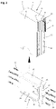
- FIG 1 is a fastening device 1 for fixing a post profile 2 of a post and beam construction for facades, conservatories, skylights and the like. Shown.
- the fastening device 1 has a base part 3 that can be fastened to the ground or a lower part and a holding part 4 that can be adjusted relative to the base part 3 and fixed in a selected position for fastening the post profile.
- the holding part 4 is designed as a slide-in part to be accommodated inside the post profile 2 .
- the post profile 2 is designed as a hollow profile with two mutually parallel side walls 5 and 6, two inner and outer end walls 7 and 8 perpendicular to the side walls 4 and 5, and an interior space 9 designed as a cavity.
- the outer end wall 8 pointing to the outside of the mullion-transom construction contains an outwardly protruding web 10 with a receiving channel 11 open to the outside for fastening screws or other fastening elements, through the holding profiles (not shown here) or a holding structure for holding glass panes or others Facade elements on the outer end wall 8 can be attached.
- receiving grooves 12 running in the longitudinal direction of the post profile 2 are also provided on the outer end wall 8 for receiving an inner seal or a sealing piece.
- the post profile 2 is designed in the form of a metal profile tube that is produced, for example, by extrusion, and that can be made of steel or aluminum. However, it can also be produced as a welded construction from a suitably bent and welded metal sheet, as a wooden or plastic construction or the like.
- the outwardly protruding web 10 on the outer end wall 8, which is directed towards the outside and is used for fastening panes of glass or other facade elements, has a receiving channel 11 designed as a screw channel in the exemplary embodiment shown. Fastening screws provided with a cutting thread, for example, can be screwed into the receiving channel 11 for fastening holding profiles or other supporting or facade elements.
- the post profile 2 in the lower part of the outer end wall 8 directed to the outside has a recessed, flattened area 13 without a web 10 projecting outwards and without receiving grooves 12 .
- Bores 14 for fastening the in figure 3 provided holding profile 4 shown in more detail.
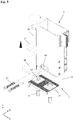
- the retaining part 4 designed as an insert profile has a block-shaped insert body 15 adapted to the inner contour of the post profile 2 with a U-shaped cross section and lower contact surfaces 16 for contacting a lower end face of the post profile 2 .
- the holding part 4 contains two downwardly projecting parallel legs 17 and a downwardly open slot 18 arranged between them for receiving the base part 3 .
- In the two legs 17 of the holding part 4 there are two rectangular openings 19 running in the longitudinal direction of the slot 18 and open towards the end faces of the holding part 4 for inserting a figure 4 shown fork-shaped lifting element 20 of an actuating device 21 explained in more detail below is provided.
- Bores 22 for screws 23 are also arranged on the end faces of the two legs 17 .
- lateral through-openings 24 are also provided for fastening elements 25, which are preferably designed as self-drilling screws.
- the retaining profile 4 is inserted with its slide-in body 15 from below into the post profile 2 until the lateral lower webs 16 come to rest on the lower face of the post profile 2 .
- the screws 23, which are screwed through the holes 14 in the threaded holes 22 on the end faces of the two legs 17 of the holding profile 4 the holding profile 4 is fixed inside the post profile 2.
- Out of figure 1 shows that also in the inner end wall 7 of the post profile 2 with the openings 19 in the holding profile 4 aligned openings 26 for inserting the fork-shaped lifting element 20 are provided.
- the openings 26 are at one corresponding recess at the lower end of the inner end wall 7 of the post profile 2 is arranged.
- the adjusting device 21 used only for the alignment of the post profile 2 can be dismantled and reused after the post profile 2 has been attached.
- it contains an adjusting screw 28 which is arranged in a thread 27 of the lifting element 20 and whose lower end can be supported on a shim 29 .
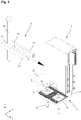
- the angular base part 3 that can be seen particularly well has a horizontal base plate 30 and a holding web 31 perpendicular thereto for introduction into the slot 18 of the holding profile 4 .
- the holding web 31 has a thickness adapted to the width of the slot 18, so that the holding profile 4 is guided on the holding web 31 in a horizontally and vertically displaceable manner.
- a corrugation 32 is provided on the upper side of the base plate 25 .
- the base parts 3 can be fastened to the base or a lower part via elongated holes in the base plate 30, threaded pins 33 with a nut 34 and retaining plates 35 which have counter-corrugation 36 matching the corrugation 32 on their underside.
- the post profile 2 with the holding part 4 fastened therein is placed on the vertical holding web 31 of the angled bottom part 3 .
- corresponding elongated holes are provided in the base plate 30 of the base part 3 so that the base part 3 can be displaced and aligned relative to the threaded pins 33 by loosening the nuts. This allows the position of the post profile 2 to be adjusted in the X-axis.
- the fork-shaped lifting element 20 of the adjusting device 21 is inserted together with the adjusting screw 28 into the post profile 2 in such a way that the two legs 37 of the fork-shaped lifting element 20 pass through the in figure 1 recognizable openings 26 in the post profile 2 in the in figure 2 shown rectangular openings 19 of the holding part 4 engage.
- the adjusting screw 28 can then be screwed in until its lower end is rotated to rest against the base plate 29 .
- the post profile 2 can then be raised and thus the position of the post profile 2 in the Z-axis can be adjusted.
- the self-tapping screws 25 can be screwed into the holes 24 and thus the post profile 2 are attached.
- the adjusting device 21 can then be removed and reused.
Landscapes
- Engineering & Computer Science (AREA)
- Architecture (AREA)
- Physics & Mathematics (AREA)
- Electromagnetism (AREA)
- Civil Engineering (AREA)
- Structural Engineering (AREA)
- Load-Bearing And Curtain Walls (AREA)
- Joining Of Building Structures In Genera (AREA)
Applications Claiming Priority (1)
| Application Number | Priority Date | Filing Date | Title |
|---|---|---|---|
| DE102020132669.6A DE102020132669A1 (de) | 2020-12-08 | 2020-12-08 | Befestigungseinrichtung und Verfahren zur Ausrichtung und Fixierung eines Pfostenprofils einer Pfosten-Riegel-Konstruktion |
Publications (2)
| Publication Number | Publication Date |
|---|---|
| EP4012131A1 true EP4012131A1 (fr) | 2022-06-15 |
| EP4012131B1 EP4012131B1 (fr) | 2025-04-09 |
Family
ID=78592565
Family Applications (1)
| Application Number | Title | Priority Date | Filing Date |
|---|---|---|---|
| EP21207046.0A Active EP4012131B1 (fr) | 2020-12-08 | 2021-11-09 | Dispositif de fixation et procédé d'alignement et de fixation d'un profilé de poteau d'une construction à poteaux et à traverses |
Country Status (2)
| Country | Link |
|---|---|
| EP (1) | EP4012131B1 (fr) |
| DE (1) | DE102020132669A1 (fr) |
Families Citing this family (1)
| Publication number | Priority date | Publication date | Assignee | Title |
|---|---|---|---|---|
| CN116497993A (zh) * | 2023-06-05 | 2023-07-28 | 中建八局第三建设有限公司 | 一种弧形幕墙施工方法 |
Citations (3)
| Publication number | Priority date | Publication date | Assignee | Title |
|---|---|---|---|---|
| EP0428962A2 (fr) | 1989-11-24 | 1991-05-29 | SCHÜCO International KG | Semelle pour montants d'une fassade |
| JPH11241440A (ja) * | 1998-02-23 | 1999-09-07 | Matsushita Electric Works Ltd | 支柱固定構造 |
| DE29919320U1 (de) * | 1999-11-03 | 1999-12-30 | Heidemann Modular Space Systems Ltd., North Yorkshire | Rahmensystem für Bauten |
-
2020
- 2020-12-08 DE DE102020132669.6A patent/DE102020132669A1/de not_active Withdrawn
-
2021
- 2021-11-09 EP EP21207046.0A patent/EP4012131B1/fr active Active
Patent Citations (3)
| Publication number | Priority date | Publication date | Assignee | Title |
|---|---|---|---|---|
| EP0428962A2 (fr) | 1989-11-24 | 1991-05-29 | SCHÜCO International KG | Semelle pour montants d'une fassade |
| JPH11241440A (ja) * | 1998-02-23 | 1999-09-07 | Matsushita Electric Works Ltd | 支柱固定構造 |
| DE29919320U1 (de) * | 1999-11-03 | 1999-12-30 | Heidemann Modular Space Systems Ltd., North Yorkshire | Rahmensystem für Bauten |
Also Published As
| Publication number | Publication date |
|---|---|
| EP4012131B1 (fr) | 2025-04-09 |
| DE102020132669A1 (de) | 2022-06-09 |
Similar Documents
| Publication | Publication Date | Title |
|---|---|---|
| DE2618442C2 (de) | Stütze für ein Geländer oder dergleichen | |
| EP0945577A2 (fr) | Dispositif de support d'encadrements pour portes ou fenêtres à la périphérie d'une ouverture de paroi | |
| DE202015104250U1 (de) | Pfosten-Riegel-Verbindung | |
| EP4012131A1 (fr) | Dispositif de fixation et procédé d'alignement et de fixation d'un profilé de poteau d'une construction à poteaux et à traverses | |
| EP0972891A2 (fr) | Dispositif pour la fixation de panneaux de verre contre des façades de bâtiments | |
| EP1098046B1 (fr) | Système d'habillage de façades et de toits de bâtiments | |
| CH695904A5 (de) | Vorrichtung zur Aufnahme eines Lauforgans. | |
| DE19623870C1 (de) | Vorrichtung zum lösbaren Verbinden von Profilstäben | |
| EP1078135A1 (fr) | Systeme de fasade pour le parement d'un edifice | |
| EP1602836B1 (fr) | Nervure raidisseuse pour bois massif | |
| EP0814215B1 (fr) | Système de façades et de système de fixation | |
| EP1342861B1 (fr) | Dispositif de fixation | |
| DE102015118360A1 (de) | Halterung für plattenelemente von brüstungen, geländern und dergleichen | |
| DE3001026A1 (de) | Vorrichtung zur befestigung eines beschlages in einem fluegelprofil fuer fenster oder tueren | |
| DE3001025A1 (de) | Vorrichtung zur befestigung eines beschlages in einem fluegelprofil fuer fenster oder tueren | |
| DE102020106891B4 (de) | T-Verbindung zwischen einem Pfosten- und Riegelprofil und Pfosten-Riegel-Konstruktion mit einer derartigen T-Verbindung | |
| DE102009026105B4 (de) | System zum Verbinden von Pfosten und Riegeln und Verwendung | |
| DE202024101757U1 (de) | Tragschiene | |
| DE4318615A1 (de) | Vorrichtung und Verfahren zum stirnseitigen Verbinden eines profilierten Bauelementes, insbesondere eines Rohres, mit einem anderen Element | |
| EP1323933B1 (fr) | Fixation pour un rail allongé ayant un profil en C avec l'ouverture dirigée vers le bas | |
| EP0379656A1 (fr) | Dispositif d'ancrage des cadres de fenêtres et portes | |
| DE20000552U1 (de) | Profilschienensystem | |
| DE19741663A1 (de) | Traggestell für Förderer, insbesondere für Rollenbahnen | |
| EP4411085A1 (fr) | Agencement doté d'éléments de construction agencés dans une cloison sèche et procédé de fixation associé | |
| DE4421107A1 (de) | Vorrichtung zur Verbindung von Profilleisten |
Legal Events
| Date | Code | Title | Description |
|---|---|---|---|
| PUAI | Public reference made under article 153(3) epc to a published international application that has entered the european phase |
Free format text: ORIGINAL CODE: 0009012 |
|
| STAA | Information on the status of an ep patent application or granted ep patent |
Free format text: STATUS: THE APPLICATION HAS BEEN PUBLISHED |
|
| AK | Designated contracting states |
Kind code of ref document: A1 Designated state(s): AL AT BE BG CH CY CZ DE DK EE ES FI FR GB GR HR HU IE IS IT LI LT LU LV MC MK MT NL NO PL PT RO RS SE SI SK SM TR |
|
| STAA | Information on the status of an ep patent application or granted ep patent |
Free format text: STATUS: REQUEST FOR EXAMINATION WAS MADE |
|
| 17P | Request for examination filed |
Effective date: 20221215 |
|
| RBV | Designated contracting states (corrected) |
Designated state(s): AL AT BE BG CH CY CZ DE DK EE ES FI FR GB GR HR HU IE IS IT LI LT LU LV MC MK MT NL NO PL PT RO RS SE SI SK SM TR |
|
| GRAP | Despatch of communication of intention to grant a patent |
Free format text: ORIGINAL CODE: EPIDOSNIGR1 |
|
| STAA | Information on the status of an ep patent application or granted ep patent |
Free format text: STATUS: GRANT OF PATENT IS INTENDED |
|
| INTG | Intention to grant announced |
Effective date: 20250103 |
|
| GRAS | Grant fee paid |
Free format text: ORIGINAL CODE: EPIDOSNIGR3 |
|
| GRAA | (expected) grant |
Free format text: ORIGINAL CODE: 0009210 |
|
| STAA | Information on the status of an ep patent application or granted ep patent |
Free format text: STATUS: THE PATENT HAS BEEN GRANTED |
|
| AK | Designated contracting states |
Kind code of ref document: B1 Designated state(s): AL AT BE BG CH CY CZ DE DK EE ES FI FR GB GR HR HU IE IS IT LI LT LU LV MC MK MT NL NO PL PT RO RS SE SI SK SM TR |
|
| REG | Reference to a national code |
Ref country code: GB Ref legal event code: FG4D Free format text: NOT ENGLISH |
|
| REG | Reference to a national code |
Ref country code: CH Ref legal event code: EP |
|
| P01 | Opt-out of the competence of the unified patent court (upc) registered |
Free format text: CASE NUMBER: APP_13072/2025 Effective date: 20250317 |
|
| REG | Reference to a national code |
Ref country code: DE Ref legal event code: R096 Ref document number: 502021007152 Country of ref document: DE |
|
| REG | Reference to a national code |
Ref country code: IE Ref legal event code: FG4D Free format text: LANGUAGE OF EP DOCUMENT: GERMAN |
|
| REG | Reference to a national code |
Ref country code: NL Ref legal event code: MP Effective date: 20250409 |
|
| PG25 | Lapsed in a contracting state [announced via postgrant information from national office to epo] |
Ref country code: NL Free format text: LAPSE BECAUSE OF FAILURE TO SUBMIT A TRANSLATION OF THE DESCRIPTION OR TO PAY THE FEE WITHIN THE PRESCRIBED TIME-LIMIT Effective date: 20250409 |
|
| PG25 | Lapsed in a contracting state [announced via postgrant information from national office to epo] |
Ref country code: ES Free format text: LAPSE BECAUSE OF FAILURE TO SUBMIT A TRANSLATION OF THE DESCRIPTION OR TO PAY THE FEE WITHIN THE PRESCRIBED TIME-LIMIT Effective date: 20250409 Ref country code: FI Free format text: LAPSE BECAUSE OF FAILURE TO SUBMIT A TRANSLATION OF THE DESCRIPTION OR TO PAY THE FEE WITHIN THE PRESCRIBED TIME-LIMIT Effective date: 20250409 Ref country code: PT Free format text: LAPSE BECAUSE OF FAILURE TO SUBMIT A TRANSLATION OF THE DESCRIPTION OR TO PAY THE FEE WITHIN THE PRESCRIBED TIME-LIMIT Effective date: 20250811 |
|
| REG | Reference to a national code |
Ref country code: LT Ref legal event code: MG9D |
|
| PG25 | Lapsed in a contracting state [announced via postgrant information from national office to epo] |
Ref country code: GR Free format text: LAPSE BECAUSE OF FAILURE TO SUBMIT A TRANSLATION OF THE DESCRIPTION OR TO PAY THE FEE WITHIN THE PRESCRIBED TIME-LIMIT Effective date: 20250710 Ref country code: NO Free format text: LAPSE BECAUSE OF FAILURE TO SUBMIT A TRANSLATION OF THE DESCRIPTION OR TO PAY THE FEE WITHIN THE PRESCRIBED TIME-LIMIT Effective date: 20250709 |
|
| PG25 | Lapsed in a contracting state [announced via postgrant information from national office to epo] |
Ref country code: PL Free format text: LAPSE BECAUSE OF FAILURE TO SUBMIT A TRANSLATION OF THE DESCRIPTION OR TO PAY THE FEE WITHIN THE PRESCRIBED TIME-LIMIT Effective date: 20250409 |
|
| PG25 | Lapsed in a contracting state [announced via postgrant information from national office to epo] |
Ref country code: BG Free format text: LAPSE BECAUSE OF FAILURE TO SUBMIT A TRANSLATION OF THE DESCRIPTION OR TO PAY THE FEE WITHIN THE PRESCRIBED TIME-LIMIT Effective date: 20250409 |
|
| PG25 | Lapsed in a contracting state [announced via postgrant information from national office to epo] |
Ref country code: HR Free format text: LAPSE BECAUSE OF FAILURE TO SUBMIT A TRANSLATION OF THE DESCRIPTION OR TO PAY THE FEE WITHIN THE PRESCRIBED TIME-LIMIT Effective date: 20250409 |
|
| PG25 | Lapsed in a contracting state [announced via postgrant information from national office to epo] |
Ref country code: RS Free format text: LAPSE BECAUSE OF FAILURE TO SUBMIT A TRANSLATION OF THE DESCRIPTION OR TO PAY THE FEE WITHIN THE PRESCRIBED TIME-LIMIT Effective date: 20250709 |
|
| PG25 | Lapsed in a contracting state [announced via postgrant information from national office to epo] |
Ref country code: IS Free format text: LAPSE BECAUSE OF FAILURE TO SUBMIT A TRANSLATION OF THE DESCRIPTION OR TO PAY THE FEE WITHIN THE PRESCRIBED TIME-LIMIT Effective date: 20250809 |
|
| PG25 | Lapsed in a contracting state [announced via postgrant information from national office to epo] |
Ref country code: LV Free format text: LAPSE BECAUSE OF FAILURE TO SUBMIT A TRANSLATION OF THE DESCRIPTION OR TO PAY THE FEE WITHIN THE PRESCRIBED TIME-LIMIT Effective date: 20250409 |
|
| REG | Reference to a national code |
Ref country code: CH Ref legal event code: U11 Free format text: ST27 STATUS EVENT CODE: U-0-0-U10-U11 (AS PROVIDED BY THE NATIONAL OFFICE) Effective date: 20251201 |
|
| PGFP | Annual fee paid to national office [announced via postgrant information from national office to epo] |
Ref country code: DE Payment date: 20251211 Year of fee payment: 5 |
|
| REG | Reference to a national code |
Ref country code: DE Ref legal event code: R097 Ref document number: 502021007152 Country of ref document: DE |
|
| PG25 | Lapsed in a contracting state [announced via postgrant information from national office to epo] |
Ref country code: SM Free format text: LAPSE BECAUSE OF FAILURE TO SUBMIT A TRANSLATION OF THE DESCRIPTION OR TO PAY THE FEE WITHIN THE PRESCRIBED TIME-LIMIT Effective date: 20250409 Ref country code: DK Free format text: LAPSE BECAUSE OF FAILURE TO SUBMIT A TRANSLATION OF THE DESCRIPTION OR TO PAY THE FEE WITHIN THE PRESCRIBED TIME-LIMIT Effective date: 20250409 |
|
| PGFP | Annual fee paid to national office [announced via postgrant information from national office to epo] |
Ref country code: AT Payment date: 20260113 Year of fee payment: 5 |
|
| PGFP | Annual fee paid to national office [announced via postgrant information from national office to epo] |
Ref country code: FR Payment date: 20251120 Year of fee payment: 5 |
|
| PGFP | Annual fee paid to national office [announced via postgrant information from national office to epo] |
Ref country code: CH Payment date: 20251201 Year of fee payment: 5 |
|
| PG25 | Lapsed in a contracting state [announced via postgrant information from national office to epo] |
Ref country code: CZ Free format text: LAPSE BECAUSE OF FAILURE TO SUBMIT A TRANSLATION OF THE DESCRIPTION OR TO PAY THE FEE WITHIN THE PRESCRIBED TIME-LIMIT Effective date: 20250409 |
|
| PG25 | Lapsed in a contracting state [announced via postgrant information from national office to epo] |
Ref country code: EE Free format text: LAPSE BECAUSE OF FAILURE TO SUBMIT A TRANSLATION OF THE DESCRIPTION OR TO PAY THE FEE WITHIN THE PRESCRIBED TIME-LIMIT Effective date: 20250409 |
|
| PG25 | Lapsed in a contracting state [announced via postgrant information from national office to epo] |
Ref country code: SK Free format text: LAPSE BECAUSE OF FAILURE TO SUBMIT A TRANSLATION OF THE DESCRIPTION OR TO PAY THE FEE WITHIN THE PRESCRIBED TIME-LIMIT Effective date: 20250409 Ref country code: RO Free format text: LAPSE BECAUSE OF FAILURE TO SUBMIT A TRANSLATION OF THE DESCRIPTION OR TO PAY THE FEE WITHIN THE PRESCRIBED TIME-LIMIT Effective date: 20250409 |
|
| PG25 | Lapsed in a contracting state [announced via postgrant information from national office to epo] |
Ref country code: IT Free format text: LAPSE BECAUSE OF FAILURE TO SUBMIT A TRANSLATION OF THE DESCRIPTION OR TO PAY THE FEE WITHIN THE PRESCRIBED TIME-LIMIT Effective date: 20250409 |
|
| PLBE | No opposition filed within time limit |
Free format text: ORIGINAL CODE: 0009261 |
|
| STAA | Information on the status of an ep patent application or granted ep patent |
Free format text: STATUS: NO OPPOSITION FILED WITHIN TIME LIMIT |
|
| REG | Reference to a national code |
Ref country code: CH Ref legal event code: L10 Free format text: ST27 STATUS EVENT CODE: U-0-0-L10-L00 (AS PROVIDED BY THE NATIONAL OFFICE) Effective date: 20260218 |
|
| 26N | No opposition filed |
Effective date: 20260112 |