EP4012148B1 - Verbinder zur mechanischen verbindung von rahmenprofilen mit pfosten-, kämpfer- oder sprossenprofilen im fenster- und türenbau sowie diesen umfassende verbindung - Google Patents
Verbinder zur mechanischen verbindung von rahmenprofilen mit pfosten-, kämpfer- oder sprossenprofilen im fenster- und türenbau sowie diesen umfassende verbindung Download PDFInfo
- Publication number
- EP4012148B1 EP4012148B1 EP21213661.8A EP21213661A EP4012148B1 EP 4012148 B1 EP4012148 B1 EP 4012148B1 EP 21213661 A EP21213661 A EP 21213661A EP 4012148 B1 EP4012148 B1 EP 4012148B1
- Authority
- EP
- European Patent Office
- Prior art keywords
- profile
- connector
- transom
- mullion
- connection
- Prior art date
- Legal status (The legal status is an assumption and is not a legal conclusion. Google has not performed a legal analysis and makes no representation as to the accuracy of the status listed.)
- Active
Links
Images

Classifications
-
- E—FIXED CONSTRUCTIONS
- E06—DOORS, WINDOWS, SHUTTERS, OR ROLLER BLINDS IN GENERAL; LADDERS
- E06B—FIXED OR MOVABLE CLOSURES FOR OPENINGS IN BUILDINGS, VEHICLES, FENCES OR LIKE ENCLOSURES IN GENERAL, e.g. DOORS, WINDOWS, BLINDS, GATES
- E06B3/00—Window sashes, door leaves, or like elements for closing wall or like openings; Layout of fixed or moving closures, e.g. windows in wall or like openings; Features of rigidly-mounted outer frames relating to the mounting of wing frames
- E06B3/96—Corner joints or edge joints for windows, doors, or the like frames or wings
- E06B3/964—Corner joints or edge joints for windows, doors, or the like frames or wings using separate connection pieces, e.g. T-connection pieces
- E06B3/9642—Butt type joints with at least one frame member cut off square; T-shape joints
-
- E—FIXED CONSTRUCTIONS
- E06—DOORS, WINDOWS, SHUTTERS, OR ROLLER BLINDS IN GENERAL; LADDERS
- E06B—FIXED OR MOVABLE CLOSURES FOR OPENINGS IN BUILDINGS, VEHICLES, FENCES OR LIKE ENCLOSURES IN GENERAL, e.g. DOORS, WINDOWS, BLINDS, GATES
- E06B3/00—Window sashes, door leaves, or like elements for closing wall or like openings; Layout of fixed or moving closures, e.g. windows in wall or like openings; Features of rigidly-mounted outer frames relating to the mounting of wing frames
- E06B3/96—Corner joints or edge joints for windows, doors, or the like frames or wings
- E06B3/964—Corner joints or edge joints for windows, doors, or the like frames or wings using separate connection pieces, e.g. T-connection pieces
- E06B3/9641—Corner joints or edge joints for windows, doors, or the like frames or wings using separate connection pieces, e.g. T-connection pieces part of which remains visible
Definitions
- the present invention relates to a connector for mechanically connecting frame profiles to mullion, transom or lattice profiles in window and door construction, which comprises a connecting plate which has frame holes for fastening the connecting plate to the frame profile, and at least one penetration element for penetrating a hollow chamber of the frame profile. Furthermore, the present invention relates to a connection which comprises the connector according to the invention.
- a generic connector is from the DE 10 2013 223 968 B4
- the connector disclosed therein is used to create a butt connection between a post profile and a frame profile of a window or door and has a support body which is inserted in its longitudinal direction into the post profile which is open at the front and fixed in the post profile.
- the connector is fixed to the frame profile and the post is inserted into the frame by sliding it onto the support body.
- it is necessary that the frame formed from the frame profiles is pushed apart, which is particularly complex for small window sizes and requires spreading aids to spread the frame.
- Further connectors are known from the documents EP 2 495 385 A2 , CH 563 536 A5 , EP 0 663 509 A2 , DE 20 2011 005 349 U1 and EP 1 055 796 A2 known.
- the present invention is based on the object of providing a connector for mechanically connecting frame profiles to post, transom or muntin profiles in window and door construction, which overcomes the problems mentioned above with prior art connectors, which can be manufactured inexpensively, is easy to install and does not require the use of a spreading aid during installation, particularly for small window sizes.
- the present invention provides a connection between a frame profile and a post, transom or muntin profile, which comprises such a connector.
- the penetration element which penetrates into a hollow chamber of the frame profile in the connection according to the invention, comprises at least one transfer element, which makes it significantly easier to transfer the post, transom or muntin profile over the insertion element.
- the cut piece of the post, transom or muntin profile can then be easily moved over the connector according to the invention using the transfer element, so that spreading the frame into which the post, transom or muntin is to be inserted is no longer necessary. This greatly simplifies the manufacture of a window that comprises a connection according to the invention.
- the present invention therefore relates to a connector for mechanically connecting a frame profile to a post, transom or muntin profile in window and door construction, wherein the connector comprises a connecting plate which has frame holes for fastening the connecting plate to the frame profile, and at least one insertion element for insertion into a hollow chamber of the post, transom or muntin profile, wherein the insertion element comprises at least one transfer element for easier transfer of the post, transom or muntin profile over the insertion element and the connector comprises at least one contact element for contact with a wall of the post, transom or muntin profile, wherein the connector is characterized according to the invention in that at least one contact element is mounted so as to be rotatable about an axis.
- the present invention relates to a connection between a frame profile and a post, transom or muntin profile, wherein the connection comprises a frame profile, a post, transom or muntin profile and a connector according to the invention.
- the insertion element can alternatively also be referred to as a support body.
- the transfer element is designed as an inclined plane or insertion slope.
- Such a design of the transfer element as an inclined plane or insertion slope on the connector according to the invention can be implemented particularly easily.
- the purpose of the invention namely the insertion of a post, a transom or a rung into a frame without the need for tools, is made particularly easy.
- the connector comprises at least one contact element for contact with a wall of the post, transom or rung profile.
- a contact element on the profile to be inserted into the frame increases the stability of the connection according to the invention.
- it can be used to clamp the connector according to the invention to the post, transom or rung profile by means of clamping elements, in particular clamping screws.
- the connector according to the invention preferably comprises two such contact elements, which preferably rest on opposite sides of the post, transom or rung profile.
- at least one contact element is designed to be movable about an axis.
- the contact element can stand up when the piece of the post, transom or rung profile is placed on it and can rest against the post, transom or rung profile after it has been erected. This further considerably simplifies the production of a connection according to the invention.
- all contact elements of the connector according to the invention have a corresponding mobility about an axis.
- the connecting plate and/or the penetration element also has at least one clamping hole into which a clamping screw can be screwed in to clamp the connecting plate to the frame profile. This ensures a particularly stable connection of the connector according to the invention to the frame profile.
- the connector according to the invention is a component made of aluminum, stainless steel, an aluminum die-cast alloy, a zinc die-cast alloy, an aluminum-zinc die-cast alloy, acrylonitrile-styrene-acrylate (ASA), polyamide (PA), polyoxymethylene (POM) or fiber-reinforced polymers, in particular glass fiber-reinforced polymers, and mixtures of the aforementioned materials.
- ASA acrylonitrile-styrene-acrylate
- PA polyamide
- POM polyoxymethylene
- fiber-reinforced polymers in particular glass fiber-reinforced polymers, and mixtures of the aforementioned materials.
- different sections or regions of the connector according to the invention can be made of different materials. The materials mentioned have proven to be particularly suitable, with a component made of an aluminum-zinc die-cast alloy in particular proving to be particularly resistant.
- the connecting plate of the connector according to the invention is made of metal, preferably of zinc or a zinc die-cast alloy.
- the height of the penetration element above the connecting plate is in the range of 5% to 40% of the width of the hollow chamber of the post, transom or rung profile into which the penetration element penetrates.
- the height of the penetration element above the connecting plate is in the range of 10% to 25% of the width of the hollow chamber of the post, transom or rung profile into which the penetration element penetrates.
- the side of the insertion element opposite the at least one transfer element runs, at least in sections, essentially parallel to a wall of the hollow chamber of the post, transom or rung profile into which the insertion element is to be inserted.
- This allows the piece of the post, transom or rung profile to snap behind the insertion element after being transferred over the insertion element of the connector according to the invention.
- This contributes significantly to the stability of the connection according to the invention.
- such a connection according to the invention is initially stable even before clamping, in particular screwing.
- the insertion element has at least one elevation protruding away from the side facing the frame profile. This can ensure that when the connection is created between the connector and the frame profile, the elevations are pressed into the frame profile, thereby creating a positive connection in addition to the surface connection between the connector and the frame profile. It can be particularly advantageous if the elevation protrudes conically from the insertion element. The conical shape of the elevation promotes the penetration of the elevation into the frame profile. In this regard, it can prove particularly advantageous if the material of the insertion element on the side facing the frame profile, which has the elevations protruding from the insertion element, consists of a harder material than the material of the frame profile. This further promotes the penetration of the elevations into the frame profile and thus the positive connection between the connector and the frame profile.
- the connecting plate of the connector according to the invention comprises a sealing element on its side facing away from the inserted element.
- This sealing element can preferably be designed as an adhesive-bonded sealing cushion, in particular made of EPDM cellular rubber or PE.
- an overmolded TPE can also be used for sealing.
- connection according to the invention it may be advantageous if the post, transom or rafter profile is fixed at its position before the post, transom or rung profile into a frame formed from the frame profile comprises an insertion aid on the side facing the connector.
- This also makes the production of the connection according to the invention considerably easier because the post, transom or rung profile can be guided even more easily over the insertion element.
- the insertion aid is designed as a flattening or rounding of a profile edge of the post, transom or rung profile.
- connection further comprises clamping elements, in particular screws, for connecting the frame profile and the post, transom or rung profile to the connector.
- clamping elements serve to finally fix the connection according to the invention.
- the at least one contact element of the connector according to the invention comprises at least one elevation, which engages in a corresponding recess, in particular a hole, in the post, transom or rung profile.
- the elevation is designed in the form of a dome.
- the elevation or dome is preferably formed on the large leg if the contact surfaces of the connector according to the invention are designed to be movable about an axis.
- the frame profile is a hollow chamber profile comprising a plurality of hollow chambers, in particular a plastic hollow profile chamber profile comprising a plurality of hollow chambers and thus, in the case of a window, it is a plastic window and in the case of a door, it is a plastic door.
- the connector according to the invention, the connection according to the invention and individual parts thereof can also be manufactured line by line or layer by layer using a line-building or layer-building manufacturing process (e.g. 3D printing), but the connector according to the invention is preferably manufactured by injection molding and the profiles further involved in the connection according to the invention are manufactured by extrusion.
- a line-building or layer-building manufacturing process e.g. 3D printing
- a connector 1 according to an embodiment of the present invention is shown in a perspective view.
- the connector 1 comprises a connecting plate 10 into which frame holes 12, 12', 12" are drilled for fastening the connecting plate 10 to a frame profile 20 ( Fig. 2 ) are inserted.
- An insertion element 14 is connected in one piece to this connecting plate 10.
- the insertion element 14 is intended to be inserted into a hollow chamber, preferably into the reinforcement chamber, of a post, transom or rung profile 30 ( Fig. 3 ) and thus contribute to the stability of a connection 40.
- the insertion element 14 is relatively flat. Its height in the Fig.
- the width of the hollow chamber of the frame profile 20, in which the insertion element 14 is arranged in the connection 10 is only about 20% of the width of the hollow chamber of the frame profile 20. This makes it easier to move the post, transom or rung profile 30 over the insertion element 14 when creating the connection 10 and thus onto the Attach connector 1.
- the insertion element 14 On one side, the insertion element 14 has an inclined plane that slopes down towards the outside of the connector 1. This inclined plane serves to facilitate the transfer of the post, transom or rung profile 30 over the insertion element 14. For the connector 1, the inclined plane therefore functions as a transfer element 16 for the easier transfer of the post, transom or rung profile 30 over the insertion element 14.
- the insertion element 14 On its upper side, the insertion element 14 has a bracing hole 15. A clamping element, in particular a clamping screw, can be guided through this bracing hole 15, which serves to brace the connector 1 with the frame profile 20.
- the side of the insertion element 14 opposite the transfer element 16 is in the Fig. 1 illustrated embodiments are essentially orthogonal to the connecting plate.
- the connector Spaced apart from this insertion element 14, the connector comprises two tab-shaped contact elements 18, 18'.
- the contact elements 18, 18' rest against two opposite outer walls of the post, transom or rung profile 30.
- the contact elements 18, 18' also have holes for the passage of clamping elements for securing the connector 1 to the post, transom or rung profile 30.
- the two contact elements 18, 18' are also integrally formed on the connecting plate 10.
- the connector 1 is in the Fig. 1
- the embodiment shown is manufactured as a cast part from an aluminum-zinc die-cast alloy.
- connection 40 the connector 1 is placed on the frame profile 20 in the appropriate position and secured in this position by means of clamping elements, in particular by means of screws that are guided through the frame holes 12, 12', 12".
- the connecting plate 10 is adapted to the geometry of the fold of the frame profile 20 on its underside facing the frame profile 20.
- a piece of a post profile 30 is then inserted into a frame formed from the frame profiles 20.
- a piece of a suitable length is first cut from a rod of the post profile 30.
- a milling 32 is made in the post profile 30 so that the contour of the post profile 30 is adapted to an overlap 22 of the frame profile 30, which in Fig.
- FIG. 2 can be clearly seen in which a cross-sectional view of a connection 40 with the Fig. 1 shown connector 1 during its production.
- an insertion aid 34 is added to the post profile 30 at this end. In the Fig. 2 In the embodiment shown, this is achieved by removing material from the post profile 30.
- the insertion aid 34 is designed as a rounded section of a profile edge 36 of the post profile 30. Alternatively, a bevel of the profile edge 36 is also conceivable.
- the insertion aid 34 designed as a rounded section allows the end of the post profile 30 to be easily pushed along the insertion element 14 of the connector 1.
- connection 40 is pre-fixed.
- the contact elements 18, 18' of the connector 1 rest against opposite outer walls of the post profile 30.
- the post profile 30 is thus arranged between the contact elements 18, 18' of the connector 1.
- the connection 10 is finally fixed by screwing the connection plate 10 to the frame profile 20 and the contact elements 18, 18' to the post profile 30.
- the resulting connection 40 is shown in Fig. 3 shown in a perspective view, whereby the screws used for final fixation are not shown.
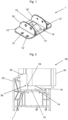
- a connector 1 according to a further embodiment of the present invention is shown in a perspective view.
- the connector 1 according to the invention comprises the connecting plate 10 into which frame holes 12, 12', 12" for fastening the connecting plate 10 to a frame profile 20 ( Fig. 5 ) are inserted.
- this connecting plate 10 With this connecting plate 10, in turn, an insertion element 14 in one piece.
- the insertion element 14 can also be inserted into a hollow chamber, preferably into the reinforcement chamber, of a post, transom or rung profile 30 ( Fig. 5 ) and thus contribute to the stability of a connection 40 according to the invention.
- the insertion element 14 corresponds to the insertion element 14 of the Fig. 1 connector 1 shown.
- the connector 1 shown is the contact elements 18, 18' of the Fig. 4
- the connector 1 shown is not rigidly connected to the connecting plate 10.
- two contact elements 18, 18' are also present. These are arranged at a distance from the insertion element 14.
- the contact elements 18, 18' are each connected to the connecting plate 10 so as to be rotatable about an axis, the axes of rotation of the contact elements 18, 18' each lying in the plane of the connecting plate 10.
- the axes of rotation run essentially parallel to the direction in which the post profile 30 is introduced into the frame formed from the frame profiles 20 during the production of the connection 40 according to the invention.
- the contact elements 18, 18' have a substantially L-shaped geometry, each with a large leg 19 and a small leg 19' arranged substantially perpendicularly thereto.
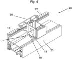
- the connecting plate 10 has recesses for receiving the small legs 19' when the contact elements 18, 18' are erected ( Fig. 5 ).
- the connector 1 is also in the Fig. 1 illustrated embodiment is manufactured as a cast part from an aluminum-zinc die-cast alloy, wherein the contact elements 18, 18', also manufactured as a cast part, are subsequently rotatably connected to the connecting plate 10.
- the contact elements 18, 18' can comprise at least one elevation, which can be designed as a dome, which engages in a corresponding recess, in particular a hole, of the post, transom or rung profile 30.
- the connector 12 according to the invention preferably comprises such elevations, which are each arranged on the large leg 19 of the contact elements 18, 18'. These elevations engage two recesses, which each are arranged on opposite profile walls of the post, transom or rung profile 30.
- the preparation of a compound 40 according to the invention is carried out in accordance with the procedure described with respect to the embodiment according to Fig. 1 to Fig. 3
- the post profile 30 engages the insertion element 14, the insertion element 14 presses in accordance with the procedure described in Fig. 4 and Fig. 5
- the post profile 30 is placed on the small legs 19' of the contact elements 18, 18'.
- the contact elements 18, 18' are raised until the large leg 19 of the contact elements 18, 18' rests against an outer wall of the post profile 30.
- the post profile 30 is pre-fixed in the connection 40 according to the invention.
- the final fixing of the connection 40 according to the invention by means of screws can now be carried out easily.
- the resulting connection 40 according to the invention is in Fig. 5 shown in a perspective view, whereby the screws used for final fixation are not shown.
Landscapes
- Engineering & Computer Science (AREA)
- Civil Engineering (AREA)
- Structural Engineering (AREA)
- Load-Bearing And Curtain Walls (AREA)
- Mutual Connection Of Rods And Tubes (AREA)
Description
- Die vorliegende Erfindung betrifft einen Verbinder zur mechanischen Verbindung von Rahmenprofilen mit Pfosten-, Kämpfer- oder Sprossenprofilen im Fenster- und Türenbau, der eine Verbindungsplatte, die Rahmenbohrungen zur Befestigung der Verbindungsplatte an dem Rahmenprofil aufweist, und mindestens ein Eindringenelement zum Eindringen in eine Hohlkammer des Rahmenprofils umfasst. Darüber hinaus bezieht sich die vorliegende Erfindung auf eine Verbindung, die den erfindungsgemäßen Verbinder umfasst.
- Ein gattungsgemäßer Verbinder ist aus der
DE 10 2013 223 968 B4 bekannt. Der darin offenbarte Verbinder wird zum Herstellen einer stumpfen Verbindung zwischen einem Pfostenprofil und einem Rahmenprofil eines Fensters oder einer Tür verwendet und weist einen Stützkörper auf, der in seiner Längsrichtung in das stirnseitig offene Pfostenprofil eingeführt und im Pfostenprofil fixiert wird. Zum Verbinden von Pfosten- und Rahmenprofil wird der Verbinder an dem Rahmenprofil fixiert und der Pfosten durch Aufschieben auf den Stützkörper in den Rahmen eingebracht. Dazu ist es notwendig, dass der aus den Rahmenprofilen gebildete Rahmen auseinandergedrückt wird, was insbesondere bei kleinen Fenstergrößen aufwendig ist und Spreizhilfsmittel zum Aufspreizen des Rahmens erfordert. Weitere Verbinder sind aus den SchriftenEP 2 495 385 A2 ,CH 563 536 A5 EP 0 663 509 A2 ,DE 20 2011 005 349 U1 undEP 1 055 796 A2 bekannt. - Dementsprechend liegt der vorliegenden Erfindung die Aufgabe zugrunde, einen Verbinder zur mechanischen Verbindung von Rahmenprofilen mit Pfosten-, Kämpfer- oder Sprossenprofilen im Fenster- und Türenbau zur Verfügung zu stellen, der die genannten Probleme von Verbindern des Standes der Technik überwindet, der kostengünstig hergestellt werden kann, einfach einzubauen ist und beim Einbau insbesondere bei kleinen Fenstergrößen nicht die Verwendung eines Speizhilfsmittels erfordert. Darüber hinaus liegt die vorliegende Erfindung Bereitstellung einer Verbindung zwischen einem Rahmenprofile und einem Pfosten-, Kämpfer- oder Sprossenprofil, die einen derartigen Verbinder umfasst.
- Erfindungsgemäß wird diese Aufgabe durch einen Verbinder mit den Merkmalen des Anspruches 1 sowie durch eine Verbindung mit den Merkmalen des Anspruchs 7 gelöst. Bevorzugte Ausführungsformen des erfindungsgemäßen Verbinders bzw. der erfindungsgemäßen Verbindung sind in den abhängigen Ansprüchen beschrieben.
- Es hat sich überraschenderweise gezeigt, dass auf ein Aufspreizen des Rahmens unter Verwendung eines Spreizhilfsmittels verzichtet werden kann, wenn das Eindringelement, das in der erfindungsgemäßen Verbindung in eine Hohlkammer des Rahmenprofils eindringt, mindestens ein Überführungselement umfasst, durch das das Überführen des Pfosten-, Kämpfer- oder Sprossenprofils über das Einbringelement signifikant erleichtert ist. Das abgelängte Stück des Pfosten-, Kämpfer- oder Sprossenprofils lässt sich dann mithilfe des Überführungselements leicht über den erfindungsgemäßen Verbinder bewegen, sodass es eines Aufspreizens des Rahmens, in den der Pfosten, der Kämpfer oder die Sprosse eingesetzt werden soll, nicht mehr bedarf. Dies vereinfacht die Herstellung eines Fensters, dass eine erfindungsgemäße Verbindung umfasst, ganz erheblich.
- Die vorliegende Erfindung bezieht sich damit auf einen Verbinder zur mechanischen Verbindung eines Rahmenprofils mit einem Pfosten-, Kämpfer- oder Sprossenprofil im Fenster- und Türenbau, wobei der Verbinder eine Verbindungsplatte, die Rahmenbohrungen zur Befestigung der Verbindungsplatte an dem Rahmenprofil aufweist, und mindestens ein Einbringelement zum Einbringen in eine Hohlkammer des Pfosten-, Kämpfer- oder Sprossenprofils umfasst, wobei das Einbringelement mindestens ein Überführungselement zum erleichterten Überführen des Pfosten-, Kämpfer- oder Sprossenprofils über das Einbringelement umfasst und der Verbinder mindestens ein Anlageelement zur Anlage an einer Wand des Pfosten-, Kämpfer- oder Sprossenprofils umfasst, wobei sich der Verbinder erfindungsgemäß dadurch auszeichnet, dass mindestens ein Anlageelement um eine Achse drehbar gelagert ist. Darüber hinaus bezieht sich die vorliegende Erfindung auf eine Verbindung zwischen einem Rahmenprofil und einem Pfosten-, Kämpfer- oder Sprossenprofil, wobei die Verbindung ein Rahmenprofil, ein Pfosten-, Kämpfer- oder Sprossenprofil und einen erfindungsgemäßen Verbinder umfasst.
- Das Einbringelement kann alternativ auch als Stützkörper bezeichnet werden.
- In Bezug auf den erfindungsgemäßen Verbinder kann es sich als vorteilhaft erweisen, wenn das Überführungselement als schiefe Ebene oder Einführungsschräge ausgebildet ist. Eine derartige Ausgestaltung des Überführungselements als schiefe Ebene oder Einführungsschräge am erfindungsgemäßen Verbinder lässt sich besonders leicht realisieren. Darüber hinaus wird der erfindungsgemäße Zweck, nämlich das hilfsmittelfreie Einbringen eines Pfostens, eines Kämpfers oder einer Sprosse in einen Rahmen, besonders stark erleichtert.
- Erfindungsgemäß umfasst der Verbinder mindestens ein Anlageelement zur Anlage an einer Wand des Pfosten-, Kämpfer- oder Sprossenprofils. Ein derartiges Anlageelement an dem in den Rahmen einzusetzenden Profil erhöht die Stabilität erfindungsgemäßen Verbindung. Insbesondere kann es dazu dienen, mittels Spannelementen, insbesondere Spannschrauben, den erfindungsgemäßen Verbinder mit dem Pfosten-, Kämpfer- oder Sprossenprofil zu verspannen. Vorzugsweise umfasst der erfindungsgemäße Verbinder zwei derartige Anlageelemente, die vorzugsweise an einander gegenüberliegenden Seiten des Pfosten-, Kämpfer- oder Sprossenprofils anliegend. Gemäß der vorliegenden Erfindung ist mindestens ein Anlageelement um eine Achse beweglich ausgebildet. Dadurch kann sich das Anlageelement beim Aufsetzen des Stücks des Pfosten-, Kämpfer- oder Sprossenprofils aufrichten und nach dem aufrichten an dem Pfosten-, Kämpfer- oder Sprossenprofil anliegen. Dies vereinfacht die Herstellung einer erfindungsgemäßen Verbindung weiter beträchtlich. In besonders bevorzugten Ausführungsformen weisen alle Anlageelemente des erfindungsgemäßen Verbinders eine entsprechende Beweglichkeit um eine Achse auf. Zusätzlich oder alternativ dazu kann es von Vorteil sein, wenn die Verbindungsplatte und/oder das Eindringenelement zusätzlich mindestens eine Verspannbohrung aufweist, in die eine Spannschraube zur Verspannung der Verbindungsplatte mit dem Rahmenprofil einschraubbar ist. Dies gewährleistet eine besonders stabile Verbindung des erfindungsgemäßen Verbinders zum Rahmenprofil.
- Gemäß einer bevorzugten Ausführungsform der vorliegenden Erfindung ist der erfindungsgemäße Verbinder ein Bauteil aus Aluminium, Edelstahl, einer Aluminium-Druckgusslegierung, einer Zink-Druckgusslegierung, einer Aluminium-Zink-Druckgusslegierung, Acrylnitril-Styrol-Acrylester (ASA), Polyamid (PA), Polyoxymethylen (POM) oder faserverstärkten Polymeren, insbesondere glasfaserverstärkten Polymeren, sowie Gemischen der vorgenannten Materialien. Dabei können insbesondere verschiedene Abschnitte oder Bereiche des erfindungsgemäßen Verbinders aus unterschiedlichen Materialien hergestellt sein. Die genannten Materialien haben sich als besonders geeignet erwiesen, wobei sich insbesondere um ein Bauteil aus eine Aluminium-Zink-Druckgusslegierung als besonders widerstandsfähig erwiesen hat. Insbesondere ist die Verbindungsplatte des erfindungsgemäßen Verbinders aus Metall, vorzugsweise aus Zink oder einer Zink-Druckgusslegierung ausgebildet.
- In bevorzugten Ausführungsformen des erfindungsgemäßen Verbinders liegt die Höhe des Eindringelements über der Verbindungsplatte im Bereich von 5 % bis 40 % der Breite der Hohlkammer des Pfosten-, Kämpfer- oder Sprossenprofils in die das Eindringelement eindringt. Insbesondere liegt die Höhe des Eindringelements über der Verbindungsplatte im Bereich von 10 % bis 25 % der Breite der Hohlkammer des Pfosten-, Kämpfer- oder Sprossenprofils in die das Eindringelement eindringt. Eine derart flache Bauform des Eindringelements vereinfacht die Montage einer erfindungsgemäßen Verbindung weiter, weil das Überführen des in den Rahmen einzusetzenden Profilstücks über das Eindringelement leicht erfolgen kann.
- Es kann auch hilfreich sein, wenn die dem mindestens einem Überführungselement gegenüberliegende Seite des Einbringelements zumindest abschnittsweise im Wesentlichen parallel zu einer Wand der Hohlkammer des Pfosten-, Kämpfer- oder Sprossenprofils verläuft, in die das Einbringelement eingebracht werden soll. Dadurch kann das Stück des Pfosten-, Kämpfer- oder Sprossenprofils nach dem Überführen über das Einbringenelement des erfindungsgemäßen Verbinders das Einbringelement hinterrasten. Dies trägt erheblich zur Stabilität der erfindungsgemäßen Verbindung bei. Darüber hinaus ist eine solche erfindungsgemäße Verbindung auch vor dem Verspannen, insbesondere dem Verschrauben, zunächst stabil.
- Es kann sich des Weiteren als vorteilhaft erweisen, wenn das Einbringelement an der dem Rahmenprofil zugewandten Seite mindestens eine von ihr wegragende Erhebung aufweist. Dadurch kann erreicht werden, dass bei Erzeugung der Verbindung zwischen Verbinder und Rahmenprofil die Erhebungen in das Rahmenprofil gedrückt werden und dadurch zusätzlich zur Flächenverbindung zwischen Verbinder und Rahmenprofil eine formschlüssige Verbindung erzielt wird. Dabei kann es von besonderem Vorteil sein, wenn die Erhebung kegelförmig aus dem Einbringelement herausragt. Durch die Kegelform der Erhebung wird das Eindringen der Erhebung in das Rahmenprofil gefördert. Diesbezüglich kann es sich als besonders günstig erweisen, wenn der Werkstoff des Einbringelements der dem Rahmenprofil zugewandten Seite, die die aus dem Einbringelement herausragenden Erhebungen aufweist, aus einem härteren Werkstoff besteht als der Werkstoff des Rahmenprofils. Dadurch wird das Eindringen der Erhebungen in das Rahmenprofil und damit der Formschluss zwischen Verbinder und Rahmenprofil weiter gefördert.
- Es kann hilfreich sein, wenn die Verbindungsplatte des erfindungsgemäßen Verbinders an ihrer dem einbringen elementabgewandten Seite ein Dichtungselement umfasst. Dieses Dichtungselement kann vorzugsweise als aufgeklebtes Dichtkissen, insbesondere aus aus EPDM-Zellkautschuk oder PE, ausgebildet sein. Alternativ kann auch ein umspritztes TPE zur Abdichtung eingesetzt werden.
- In Bezug auf die erfindungsgemäße Verbindung kann es günstig sein, wenn das Pfosten-, Kämpfer- oder Sprossenprofil an seiner vor dem Einsetzen des Pfosten-, Kämpfer- oder Sprossenprofils in einen aus dem Rahmenprofil gebildeten Rahmen dem Verbinder zugewandten Seite eine Einbringhilfe umfasst. Auch dies erleichtert die Herstellung der erfindungsgemäßen Verbindung beträchtlich, weil das Pfosten-, Kämpfer- oder Sprossenprofil noch leichter über das Einbringelement geführt werden kann. Dabei kann es sich als nützlich erweisen, wenn die Einbringhilfe als Abflachung oder Abrundung einer Profilkante des Pfosten-, Kämpfer- oder Sprossenprofils ausgebildet ist.
- Es kann auch hilfreich sein, wenn die Verbindung weiter Spannelemente, insbesondere Schrauben, zur Verbindung des Rahmenprofils sowie des Pfosten-, Kämpfer- oder Sprossenprofils mit dem Verbinder umfasst. Derartige Spannelemente dienen zur endgültigen Fixierung der erfindungsgemäßen Verbindung.
- Darüber hinaus kann es von Vorteil sein, wenn das mindestens eine Anlageelement des erfindungsgemäßen Verbinders mindestens eine Erhöhung, umfasst, die jeweils in eine entsprechende Ausnehmung, insbesondere eine Bohrung, des Pfosten-, Kämpfer- oder Sprossenprofil eingreift. Auf diese Weise wird das Pfosten-, Kämpfer- oder Sprossenprofil bei der Erzeugung der erfindungsgemäßen Verbindung leicht in seine richtige Position am Rahmenprofil geführt. In besonders bevorzugten Ausführungsformen der erfindungsgemä-ßen Verbindung ist die Erhöhung in Form eines Doms ausgebildet. Die Erhöhung bzw. der Dom ist dabei bevorzugt am großen Schenkel ausgebildet, wenn die Anlageflächen des erfindungsgemäßen Verbinders um eine Achse beweglich ausgebildet sind.
- Darüber hinaus gelten die in Bezug auf den erfindungsgemäßen Verbinder erläuterten Merkmale und Vorteile auch für die erfindungsgemäße Verbindung entsprechend.
- Bevorzugt handelt es sich bei dem Rahmenprofil um ein mehrere Hohlkammern umfassendes Hohlkammerprofil, insbesondere um ein mehrere Hohlkammern umfassendes Kunststoff-Hohlprofilkammerprofil und damit bei einem Fenster um ein Kunststofffenster und bei eine Tür um eine Kunststofftür.
- Der erfindungsgemäße Verbinder, die erfindungsgemäße Verbindung sowie einzelne Teile davon können auch zeilenweise oder schichtweise unter Verwendung eines zeilenaufbauenden oder schichtaufbauenden Fertigungsverfahrens (z. B. 3D-Druck) hergestellt werden, bevorzugt ist jedoch die Herstellung des erfindungsgemäßen Verbinders mittels Spritzguss und der an der erfindungsgemäßen Verbindung weiter beteiligten Profile mittels Extrusion.
- Im Folgenden soll die vorliegende Erfindung unter Bezugnahme auf die in den Figuren dargestellten Ausführungsformen im Detail erläutert werden. Anhand der Figuren wird die vorliegende Erfindung in Bezug auf eine Pfostenverbindung eines Fensters detailliert erläutert. Es versteht sich jedoch, dass die diesbezüglichen Ausführungen auch in Bezug auf eine Kämpfer- oder Sprossenverbindung oder auf eine Tür entsprechend Anwendung finden. Die
Figuren 1 bis 3 zeigen einen Verbinder ohne drehbares Lagerelement, welcher für die Verständnis der Erfindung nützlich ist, sondern nicht unter den Schutzumfang der Ansprüche fällt. DieFiguren 4 und5 zeigen einen erfindungsgemäßen Verbinder. -
Fig. 1 eine perspektivische Ansicht eines Verbinders ; -
Fig. 2 eine Querschnittsansicht einer Verbindung mit dem inFig. 1 dargestellten erfindungsgemäßen Verbinders während ihrer Erzeugung; -
Fig. 3 eine perspektivische Ansicht der inFig. 2 dargestellten Verbindung; -
Fig. 4 eine perspektivische Ansicht eines Verbinders gemäß einer Ausführungsform der vorliegenden Erfindung; und -
Fig. 5 eine perspektivische Ansicht einer erfindungsgemäßen Verbindung mit dem inFig. 4 dargestellten erfindungsgemäßen Verbinder. - In
Fig. 1 ist ein Verbinder 1 gemäß einer Ausführungsform der vorliegenden Erfindung in einer perspektivischen Ansicht dargestellt. Darin umfasst der Verbinder 1 eine Verbindungsplatte 10, in die Rahmenbohrungen 12, 12', 12" zur Befestigung der Verbindungsplatte 10 an einem Rahmenprofil 20 (Fig. 2 ) eingebracht sind. Mit dieser Verbindungsplatte 10 einstückig verbunden ist ein Einbringelement 14. Das Einbringelement 14 soll in eine Hohlkammer, vorzugsweise in die Armierungskammer, eines Pfosten-, Kämpfer- oder Sprossenprofils 30 (Fig. 3 ) eingeführt werden und so zur Stabilität einer Verbindung 40 beitragen. Das Einbringelement 14 ist relativ flach ausgebildet. So beträgt seine Höhe in der inFig. 1 dargestellten Ausführungsform lediglich etwa 20 % der Breite der Hohlkammer des Rahmenprofils 20, in die das Einbringelement 14 in der Verbindung 10 angeordnet ist. Dadurch lässt sich das Pfosten-, Kämpfer- oder Sprossenprofil 30 bei der Erzeugung der Verbindung 10 leichter über das Einbringelement 14 bewegen und dadurch auf den Verbinder 1 aufsetzen. - An einer Seite weist das Einbringelement 14 eine sich zur Außenseite des Verbinder 1 hin abfallende schiefe Ebene auf. Diese schiefe Ebene dient dazu, das Überführen des Pfosten-, Kämpfer- oder Sprossenprofils 30 über das Einbringelement 14 zu erleichtern. Für den Verbinder 1 fungiert die schiefe Ebene also als Überführungselement 16 zum erleichterten Überführen des Pfosten-, Kämpfer- oder Sprossenprofils 30 über das Einbringelement 14. An seiner Oberseite weist das Einbringelement 14 eine Verspannbohrung 15 auf. Durch diese Verspannbohrung 15 kann ein Spannelement, insbesondere eine Spannschraube, geführt werden, die zur Verspannung des Verbinders 1 mit dem Rahmenprofil 20 dient. Die dem Überführungselement 16 gegenüberliegende Seite des Einbringelements 14 ist in der in
Fig. 1 dargestellten Ausführungsformen Wesentlichen orthogonal zur Verbindungsplatte ausgebildet. - Beabstandet von diesem Einbringelement 14 umfasst der Verbinder zwei laschenförmig ausgebildete Anlageelemente 18, 18'. Die Anlageelemente 18, 18' liegen in der fertigen Verbindung 40 an zwei gegenüberliegenden Au-ßenwänden des Pfosten-, Kämpfer- oder Sprossenprofils 30 an. Auch die Anlageelemente 18, 18' weisen Bohrungen zur Durchführung von Spannelementen zur Festlegung des Verbinders 1 an dem Pfosten-, Kämpfer- oder Sprossenprofil 30 auf. Die beiden Anlageelemente 18, 18' sind ebenfalls einstückig an die Verbindungsplatte 10 angeformt.
- Der Verbinder 1 ist in der in
Fig. 1 dargestellten Ausführungsform als Gussteil aus einer Aluminium-Zink-Druckgusslegierung hergestellt. - Zur Herstellung einer Verbindung 40 wird der Verbinder 1 an der geeigneten Position auf das Rahmenprofil 20 aufgesetzt und mittels Spannelementen, insbesondere mittels Schrauben, die durch die Rahmenbohrungen 12, 12', 12" geführt sind, in dieser Position festgelegt. Um ein Verkippen des Verbinders 1 zu verhindern, ist die Verbindungsplatte 10 an ihrer dem Rahmenprofils 20 zugewandten Unterseite der Geometrie des Falzes des Rahmenprofils 20 angepasst. Danach wird ein Stück eines Pfostenprofils 30 in einen aus den Rahmenprofilen 20 gebildeten Rahmen eingesetzt. Dazu wird zunächst ein Stück mit einer geeigneten Länge aus einer Stange des Pfostenprofils 30 abgelängt. An einem Ende des Stückes des Pfostenprofils 30 wird eine Ausfräsung 32 in das Pfostenprofil 30 eingebracht, sodass die Kontur des Pfostenprofils 30 an einen Überschlag 22 des Rahmenprofils 30 angepasst ist, was in
Fig. 2 gut zu erkennen ist, in der eine Querschnittsansicht einer Verbindung 40 mit dem inFig. 1 dargestellten Verbinders 1 während ihrer Erzeugung gezeigt ist. Darüber hinaus wird dem Pfostenprofil 30 an diesem Ende eine Einbringhilfe 34 zugefügt. In der inFig. 2 dargestellten Ausführungsform ist dies durch Materialabtragung vom Pfostenprofil 30 realisiert. Die Einbringhilfe 34 ist in der gezeigten Ausführungsform als eine Abrundung einer Profilkante 36 des Pfostenprofils 30 ausgebildet. Alternativ ist auch eine Abschrägung der Profilkante 36 denkbar. Durch die als Abrundung ausgebildete Einbringhilfe 34 lässt sich das Ende des Pfostenprofils 30 leicht entlang des Einbringelements 14 des Verbinders 1 aufschieben. Ein Weiterschieben des Pfostenprofils 30 in Richtung des Überschlag 22 des Rahmenprofils 20 für dazu, dass der Überschlag 22 in der Ausfräsung 32 des Pfostenprofils 30 aufgenommen wird und das Einbringelement 14 in eine Hohlkammer des Postenprofils 30 aufgenommen wird. Da die dem Überführungselement 16 gegenüberliegende Seite des Einbringelements 14 parallel zur entsprechenden Wand der Hohlkammer des Pfostenprofils 30 ausgebildet ist, hinterrastet das Pfostenprofil 30 das Einbringelement 14, sodass die Verbindung 40 vorfixiert ist. Dabei liegen die Anlageelemente 18, 18' des Verbinders 1 an einander gegenüberliegenden Außenwänden des Pfostenprofils 30 an. Damit ist das Pfostenprofil 30 zwischen den Anlageelementen 18, 18' des Verbinders 1 angeordnet. Abschließend wird die Verbindung 10 durch Verschrauben der Verbindungsplatte 10 mit dem Rahmenprofil 20 sowie der Anlageelemente 18, 18' mit dem Pfostenprofil 30 endgültig fixiert. Die daraus resultierende Verbindung 40 ist inFig. 3 in einer perspektivischen Darstellung gezeigt, wobei die zur endgültigen Fixierung eingesetzten Schrauben nicht dargestellt sind. - Im Folgenden wird die vorliegende Erfindung unter Bezugnahme auf eine erfindungsgemäße Ausführungsform erläutert, die in
Fig. 4 undFig. 5 dargestellt ist. Um Wiederholungen zu vermeiden, wird hierin lediglich auf die Unterschiede zwischen den verschiedenen Ausführungsformen eingegangen. Ansonsten gelten die Ausführungen in Bezug auf die Ausführungsform gemäßFig. 1 bis Fig. 3 entsprechend. Identische Bezugszeichen stehen für gleiche Elemente. - In
Fig. 4 ist ein Verbinder 1 gemäß einer weiteren Ausführungsform der vorliegenden Erfindung in einer perspektivischen Ansicht dargestellt. Auch gemäß dieser Ausführungsform umfasst der erfindungsgemäße Verbinder 1 die Verbindungsplatte 10, in die Rahmenbohrungen 12, 12', 12" zur Befestigung der Verbindungsplatte 10 an einem Rahmenprofil 20 (Fig. 5 ) eingebracht sind. Mit dieser Verbindungsplatte 10 ist wiederum ein Einbringelement 14 einstückig verbunden. Das Einbringelement 14 kann ebenfalls in eine Hohlkammer, vorzugsweise in die Armierungskammer, eines Pfosten-, Kämpfer- oder Sprossenprofils 30 (Fig. 5 ) eingeführt werden und so zur Stabilität einer erfindungsgemäßen Verbindung 40 beitragen. Das Einbringelement 14 entspricht dem Einbringelement 14 des inFig. 1 dargestellten Verbinders 1. - Im Gegensatz zu dem in
Fig. 1 dargestellten Verbinder 1 sind die Anlageelemente 18, 18' des inFig. 4 dargestellten Verbinders 1 nicht starr mit der Verbindungsplatte 10 verbunden. Gemäß der inFig. 4 dargestellten Ausführungsform des erfindungsgemäßen Verbinders 1 sind ebenfalls zwei Anlageelemente 18, 18' vorhanden. Diese sind beabstandet vom Einbringelement 14 angeordnet. Die Anlageelemente 18, 18' sind jeweils um eine Achse drehbar mit der Verbindungsplatte 10 verbunden, wobei die Drehachsen der Anlageelemente 18, 18' jeweils in der Ebene der Verbindungsplatte 10 liegen. In der inFig. 4 dargestellten Ausführungsform verlaufen die Drehachsen im Wesentlichen parallel zu der Richtung, in der das Pfostenprofil 30 bei der Erzeugung der erfindungsgemäßen Verbindung 40 in den aus den Rahmenprofilen 20 gebildeten Rahmen eingebracht wird. - Die Anlageelemente 18, 18' weisen eine im Wesentlichen L-förmige Geometrie mit jeweils einem großen Schenkel 19 und einem im Wesentlichen senkrecht dazu angeordneten kleinen Schenkel 19' auf. Die Verbindungsplatte 10 weist Aussparungen zur Aufnahme der kleinen Schenkel 19' auf, wenn die Anlageelemente 18, 18' aufgerichtet werden (
Fig. 5 ). - Der Verbinder 1 ist auch in der in
Fig. 1 dargestellten Ausführungsform als Gussteil aus einer Aluminium-Zink-Druckgusslegierung hergestellt, wobei die ebenfalls als Gussteil hergestellten Anlageelemente 18, 18' nachträglich drehbar mit der Verbindungsplatte 10 verbunden werden. - In alternativen Ausführungsformen der vorliegenden Erfindung können die Anlageelemente 18, 18' mindestens eine Erhöhung, die jeweils als Dom ausgebildet sein kann, umfassen, die jeweils in eine entsprechende Ausnehmung, insbesondere eine Bohrung, des Pfosten-, Kämpfer- oder Sprossenprofil 30 eingreift. Dadurch wird das Pfosten-, Kämpfer- oder Sprossenprofil 30 bei der Erzeugung der erfindungsgemäßen Verbindung 40 exakt in seine richtige Position am Rahmenprofil geführt. Vorzugsweise umfasst der erfindungsgemäße Verbinder 12 derartige Erhöhungen, die jeweils am großen Schenkel 19 der Anlageelemente 18, 18' angeordnet sind. Diese Erhöhungen greifen zwei Ausnehmungen ein, die jeweils an einander gegenüberliegenden Profilwänden des Pfosten-, Kämpfer- oder Sprossenprofils 30 angeordnet sind.
- Die Herstellung einer erfindungsgemäßen Verbindung 40 erfolgt entsprechend der in Bezug auf die Ausführungsform gemäß den
Fig. 1 bis Fig. 3 beschriebenen Vorgehensweise. Wenn aber beim Einbringen des Pfostenprofils 30 in den aus den Rahmenprofilen 20 gebildeten Rahmen das Pfostenprofil 30 das Einbringelement 14 hinterrastet, drückt gemäß der inFig. 4 undFig. 5 gezeigten Ausführungsform der vorliegenden Erfindung das Pfostenprofil 30 auf die kleinen Schenkel 19' der Anlageelemente 18, 18'. Dadurch richten sich die Anlageelemente 18, 18' auf, bis jeweils der große Schenkel 19 Anlageelemente 18, 18' an einer Außenwand des Pfostenprofils 30 anliegt. In dieser Position ist das Postenprofil 30 in der erfindungsgemäßen Verbindung 40 vorfixiert. Die endgültige Fixierung der erfindungsgemäßen Verbindung 40 mittels Schrauben kann nun leicht erfolgen. Die daraus resultierende erfindungsgemäße Verbindung 40 ist inFig. 5 in einer perspektivischen Darstellung gezeigt, wobei die zur endgültigen Fixierung eingesetzten Schrauben nicht dargestellt sind. - Die vorliegende Erfindung wurde exemplarisch unter Bezugnahme auf die in den Figuren dargestellten Ausführungsformen der vorliegenden Erfindung im Detail beschrieben. Es versteht sich, dass die vorliegende Erfindung nicht auf die in den Figuren dargestellte Ausführungsformen beschränkt ist, sondern sich der Umfang der vorliegenden Erfindung aus den beigefügten Ansprüchen ergibt.
Claims (12)
- Verbinder (1) zur mechanischen Verbindung eines Rahmenprofils (20) mit einem Pfosten-, Kämpfer- oder Sprossenprofil (30) im Fenster- und Türenbau, umfassend:eine Verbindungsplatte (10), die Rahmenbohrungen (12) zur Befestigung der Verbindungsplatte (10) an dem Rahmenprofil (20) aufweist;mindestens ein Einbringelement (14) zum Einbringen in eine Hohlkammer des Pfosten-, Kämpfer- oder Sprossenprofils (30), wobei das Einbringelement (14) mindestens ein Überführungselement (16) zum erleichterten Überführen des Pfosten- oder Sprossenprofil (30) über das Einbringelement (14) umfasst; undmindestens ein Anlageelement (18, 18') zur Anlage an einer Wand des Pfosten- oder Sprossenprofils (30),dadurch gekennzeichnet, dassdas mindestens eine Anlageelement (18, 18') um eine Achse drehbar gelagert ist.
- Verbinder (1) nach Anspruch 1, dadurch gekennzeichnet, dass das Überführungselement (16) als schiefe Ebene oder Einführungsschräge ausgebildet ist.
- Verbinder (1) nach Anspruch 1 oder Anspruch 2, dadurch gekennzeichnet, dass die Verbindungsplatte (10) und/oder das Eindringelement (14) zusätzlich mindestens eine Verspannbohrung (15) aufweist, in die eine Spannschraube zur Verspannung des Verbinders (1) mit dem Rahmenprofil (20) einschraubbar ist.
- Verbinder (1) nach einem der Ansprüche 1 bis 3, dadurch gekennzeichnet, dass der Verbinder ein Bauteil aus Aluminium, Edelstahl, einer Aluminium-Druckgusslegierung, einer Zink-Druckgusslegierung, einer Aluminium-Zink-Druckgusslegierung, Acrylnitril-Styrol-Acrylester (ASA), Polyamid (PA), Polyoxymethylen (POM) oder faserverstärkten Polymeren, insbesondere glasfaserverstärkten Polymeren, sowie Gemischen der vorgenannten Materialien hergestellt ist.
- Verbinder (1) nach einem der Ansprüche 1 bis 4, dadurch gekennzeichnet, dass die Höhe des Einbringelements (14) über der Verbindungsplatte (10) im Bereich von 5 % bis 40 % der Breite der Hohlkammer des Pfosten-, Kämpfer- oder Sprossenprofils (30), in die das Eindringelement (14) eindringt, liegt.
- Verbinder (1) nach einem der Ansprüche 1 bis 5, dadurch gekennzeichnet, dass die dem mindestens einem Überführungselement (16) gegenüberliegende Seite (17) des Einbringelements (14) zumindest abschnittsweise im Wesentlichen parallel zu einer Wand der Hohlkammer des Pfosten-, Kämpfer- oder Sprossenprofils (30) verläuft, in die das Einbringelement (14) einbringbar ist.
- Verbindung (40) zwischen einem Rahmenprofil (20) und einem Pfosten-, Kämpfer- oder Sprossenprofil (30) eines Fensters oder einer Tür, umfassend:- ein Rahmenprofil (20);- ein Pfosten-, Kämpfer oder Sprossenprofil (30); und- einen Verbinder nach einem der Ansprüche 1 bis 6.
- Verbindung (40) nach Anspruch 7, dadurch gekennzeichnet, dass das Pfosten-, Kämpfer- oder Sprossenprofil (30) an seiner vor dem Einsetzen des Pfosten-, Kämpfer- oder Sprossenprofils (30) in einen aus dem Rahmenprofil (20) gebildeten Rahmen dem Verbinder (10) zugewandten Seite eine Einbringhilfe (34) umfasst.
- Verbindung (40) nach Anspruch 8, dadurch gekennzeichnet, dass die Einbringhilfe (34) als Abflachung oder Abrundung einer Profilkante (36) des Pfosten-, Kämpfer- oder Sprossenprofils (30) ausgebildet ist.
- Verbindung (40) nach einem der Ansprüche 7 bis 9, dadurch gekennzeichnet, dass die dem mindestens einem Überführungselement (16) gegenüberliegende Seite (17) des Einbringelements (14) zumindest abschnittsweise im Wesentlichen parallel zu einer Wand der Hohlkammer des Pfosten-, Kämpfer- oder Sprossenprofils (30) verläuft, in die das Einbringelement (14) eingebracht ist.
- Verbindung (40) nach einem der Ansprüche 7 bis 10, dadurch gekennzeichnet, dass die Verbindung (40) weiter Spannelemente zur Verbindung des Rahmenprofils (20) sowie des Pfosten-, Kämpfer- oder Sprossenprofils (30) mit dem Verbinder (10) umfasst.
- Verbindung (40) nach einem der Ansprüche 7 bis 11, dadurch gekennzeichnet, dass das mindestens eine Anlageelement (18, 18) mindestens eine Erhöhung, vorzugsweise mindestens einen Dom, umfasst, die jeweils in eine entsprechende Ausnehmung, insbesondere eine Bohrung, des Pfosten-, Kämpfer- oder Sprossenprofils (30) eingreift.
Applications Claiming Priority (1)
| Application Number | Priority Date | Filing Date | Title |
|---|---|---|---|
| DE202020107215.3U DE202020107215U1 (de) | 2020-12-14 | 2020-12-14 | Verbinder zur mechanischen Verbindung von Rahmenprofile mit Pfosten-, Kämpfer- oder Sprossenprofilen im Fenster- und Türenbau sowie diesen umfassende Verbindung |
Publications (2)
| Publication Number | Publication Date |
|---|---|
| EP4012148A1 EP4012148A1 (de) | 2022-06-15 |
| EP4012148B1 true EP4012148B1 (de) | 2024-10-30 |
Family
ID=78829337
Family Applications (1)
| Application Number | Title | Priority Date | Filing Date |
|---|---|---|---|
| EP21213661.8A Active EP4012148B1 (de) | 2020-12-14 | 2021-12-10 | Verbinder zur mechanischen verbindung von rahmenprofilen mit pfosten-, kämpfer- oder sprossenprofilen im fenster- und türenbau sowie diesen umfassende verbindung |
Country Status (2)
| Country | Link |
|---|---|
| EP (1) | EP4012148B1 (de) |
| DE (1) | DE202020107215U1 (de) |
Family Cites Families (8)
| Publication number | Priority date | Publication date | Assignee | Title |
|---|---|---|---|---|
| CH563536A5 (de) * | 1973-05-15 | 1975-06-30 | Alusuisse | |
| DE3212436A1 (de) | 1982-04-02 | 1983-10-13 | Karlstadter Fenster- und Elementebau GmbH & Co KG, 8782 Karlstadt | Kaempferklotz |
| DE9400647U1 (de) | 1994-01-15 | 1994-04-14 | PaX GmbH, 55218 Ingelheim | Kämpferverbinder |
| GB9912337D0 (en) | 1999-05-26 | 1999-07-28 | Deceuninck Plastics Ind Nv | Mechanical joint |
| DE102011013138B3 (de) * | 2011-03-04 | 2012-09-13 | Hans Dieter Grotefeld | Vorrichtung zum Einsetzen eines Kämpfers in einen Tür- oder Fensterrahmen |
| DE202011005349U1 (de) * | 2011-04-15 | 2012-07-16 | Rehau Ag + Co | Verbinder zur Erzeugung einer Verbindung zwischen einem Rahmenprofil und einem Rahmen-, Kämpfer-, Pfosten- oder Sprossenprofil eines Fensters oder einer Tür und Verbindung, die einen derartigen Verbinder umfasst |
| DE202012008665U1 (de) | 2012-09-11 | 2012-10-26 | PHI Technik für Fenster und Türen GmbH | Anordnung zum Befestigen eines Pfostens an einer Rahmenleiste eines Fensters oder einer Türe mittels eines Pfostenverbinders |
| DE102013223968B4 (de) | 2013-11-22 | 2015-07-16 | PHI Technik für Fenster und Türen GmbH | Verbindungsanordnung zum Befestigen eines Pfostens an einem Rahmenträger eines Fensters, einer Türe oder dgl. aus Kunststoff |
-
2020
- 2020-12-14 DE DE202020107215.3U patent/DE202020107215U1/de active Active
-
2021
- 2021-12-10 EP EP21213661.8A patent/EP4012148B1/de active Active
Also Published As
| Publication number | Publication date |
|---|---|
| EP4012148A1 (de) | 2022-06-15 |
| DE202020107215U1 (de) | 2022-03-15 |
Similar Documents
| Publication | Publication Date | Title |
|---|---|---|
| DE2723850C2 (de) | Möbelscharnier | |
| DE2548527C3 (de) | Beschlag zum lösbaren Verbinden zweier senkrecht aufeinanderstoßender Bauteile | |
| EP1020575B1 (de) | T-Verbindung zwischen einem Sprossen- und einem Pfostenprofil einer Fasade oder eines Lichtdaches | |
| WO2013185747A2 (de) | Halter für eine profilschiene | |
| EP2392761B1 (de) | Rahmensystem für ein Insekten- und/oder Pollenschutzgitter | |
| EP3124734B1 (de) | Verbindungsanordnung zum verbinden eines pfostens an einem rahmenprofil eines fensters oder einer türe aus kunststoff | |
| DE9116873U1 (de) | Verbindungsvorrichtung für eine Sprossenkreuzkonstruktion | |
| EP4012148B1 (de) | Verbinder zur mechanischen verbindung von rahmenprofilen mit pfosten-, kämpfer- oder sprossenprofilen im fenster- und türenbau sowie diesen umfassende verbindung | |
| EP4012149B1 (de) | Verbinder zur mechanischen verbindung von rahmenprofilen mit pfosten-, kämpfer- oder sprossenprofilen im fenster- und türenbau sowie diesen umfassende verbindung | |
| DE102012011563A1 (de) | Halter für eine Profilschiene | |
| EP1035294B1 (de) | Kämpferverbinder-Satz | |
| EP1915539B1 (de) | Kippverbinder | |
| DE202011005349U1 (de) | Verbinder zur Erzeugung einer Verbindung zwischen einem Rahmenprofil und einem Rahmen-, Kämpfer-, Pfosten- oder Sprossenprofil eines Fensters oder einer Tür und Verbindung, die einen derartigen Verbinder umfasst | |
| DE202021106237U1 (de) | Verbindungsanordnung zum Verbinden eines Pfostens mit einem Rahmenprofil eines Fensters oder einer Türe aus Kunststoff | |
| DE3128023A1 (de) | "schraubzwinge" | |
| EP2679759B1 (de) | Eckverbinder für Hohlprofilrahmen | |
| DE102017221802A1 (de) | Befestigungsklemme und Profilstabsystem | |
| DE102005053650B3 (de) | Scharnierbeschlag | |
| DE19940574C1 (de) | Anordnung zur Bildung einer Kreuzverbindung zwischen einem Längspfosten und einem Querpfosten bei einem Fenster oder einer Türe aus Kunststoff oder Leichtmetall | |
| EP2099989A2 (de) | Treibstangengetriebe | |
| EP4015757A1 (de) | Verbindung zwischen einem rahmenprofil und einem pfosten-, kämpfer- oder sprossenprofil eines fensters oder einer tür sowie verbinder für eine derartige verbindung | |
| EP0291973A2 (de) | Verbindungsstück für zwei winklig aneinanderstossende Profilstäbe von Fenster oder Türrahmen | |
| DE9414631U1 (de) | Kunststoff-Hohlprofil | |
| EP3396098B1 (de) | Halterung für wetterschenkel und verwendung davon | |
| DE102009008380A1 (de) | T-Verbindung |
Legal Events
| Date | Code | Title | Description |
|---|---|---|---|
| PUAI | Public reference made under article 153(3) epc to a published international application that has entered the european phase |
Free format text: ORIGINAL CODE: 0009012 |
|
| STAA | Information on the status of an ep patent application or granted ep patent |
Free format text: STATUS: THE APPLICATION HAS BEEN PUBLISHED |
|
| AK | Designated contracting states |
Kind code of ref document: A1 Designated state(s): AL AT BE BG CH CY CZ DE DK EE ES FI FR GB GR HR HU IE IS IT LI LT LU LV MC MK MT NL NO PL PT RO RS SE SI SK SM TR |
|
| RAP3 | Party data changed (applicant data changed or rights of an application transferred) |
Owner name: REHAU INDUSTRIES SE & CO. KG |
|
| STAA | Information on the status of an ep patent application or granted ep patent |
Free format text: STATUS: REQUEST FOR EXAMINATION WAS MADE |
|
| 17P | Request for examination filed |
Effective date: 20221213 |
|
| RBV | Designated contracting states (corrected) |
Designated state(s): AL AT BE BG CH CY CZ DE DK EE ES FI FR GB GR HR HU IE IS IT LI LT LU LV MC MK MT NL NO PL PT RO RS SE SI SK SM TR |
|
| GRAP | Despatch of communication of intention to grant a patent |
Free format text: ORIGINAL CODE: EPIDOSNIGR1 |
|
| STAA | Information on the status of an ep patent application or granted ep patent |
Free format text: STATUS: GRANT OF PATENT IS INTENDED |
|
| INTG | Intention to grant announced |
Effective date: 20240531 |
|
| GRAS | Grant fee paid |
Free format text: ORIGINAL CODE: EPIDOSNIGR3 |
|
| GRAA | (expected) grant |
Free format text: ORIGINAL CODE: 0009210 |
|
| STAA | Information on the status of an ep patent application or granted ep patent |
Free format text: STATUS: THE PATENT HAS BEEN GRANTED |
|
| AK | Designated contracting states |
Kind code of ref document: B1 Designated state(s): AL AT BE BG CH CY CZ DE DK EE ES FI FR GB GR HR HU IE IS IT LI LT LU LV MC MK MT NL NO PL PT RO RS SE SI SK SM TR |
|
| REG | Reference to a national code |
Ref country code: GB Ref legal event code: FG4D Free format text: NOT ENGLISH |
|
| REG | Reference to a national code |
Ref country code: CH Ref legal event code: EP |
|
| REG | Reference to a national code |
Ref country code: IE Ref legal event code: FG4D Free format text: LANGUAGE OF EP DOCUMENT: GERMAN |
|
| REG | Reference to a national code |
Ref country code: DE Ref legal event code: R096 Ref document number: 502021005627 Country of ref document: DE |
|
| REG | Reference to a national code |
Ref country code: LT Ref legal event code: MG9D |
|
| REG | Reference to a national code |
Ref country code: NL Ref legal event code: MP Effective date: 20241030 |
|
| PG25 | Lapsed in a contracting state [announced via postgrant information from national office to epo] |
Ref country code: PT Free format text: LAPSE BECAUSE OF FAILURE TO SUBMIT A TRANSLATION OF THE DESCRIPTION OR TO PAY THE FEE WITHIN THE PRESCRIBED TIME-LIMIT Effective date: 20250228 Ref country code: HR Free format text: LAPSE BECAUSE OF FAILURE TO SUBMIT A TRANSLATION OF THE DESCRIPTION OR TO PAY THE FEE WITHIN THE PRESCRIBED TIME-LIMIT Effective date: 20241030 Ref country code: IS Free format text: LAPSE BECAUSE OF FAILURE TO SUBMIT A TRANSLATION OF THE DESCRIPTION OR TO PAY THE FEE WITHIN THE PRESCRIBED TIME-LIMIT Effective date: 20250228 |
|
| PG25 | Lapsed in a contracting state [announced via postgrant information from national office to epo] |
Ref country code: NL Free format text: LAPSE BECAUSE OF FAILURE TO SUBMIT A TRANSLATION OF THE DESCRIPTION OR TO PAY THE FEE WITHIN THE PRESCRIBED TIME-LIMIT Effective date: 20241030 Ref country code: FI Free format text: LAPSE BECAUSE OF FAILURE TO SUBMIT A TRANSLATION OF THE DESCRIPTION OR TO PAY THE FEE WITHIN THE PRESCRIBED TIME-LIMIT Effective date: 20241030 |
|
| PG25 | Lapsed in a contracting state [announced via postgrant information from national office to epo] |
Ref country code: BG Free format text: LAPSE BECAUSE OF FAILURE TO SUBMIT A TRANSLATION OF THE DESCRIPTION OR TO PAY THE FEE WITHIN THE PRESCRIBED TIME-LIMIT Effective date: 20241030 |
|
| PG25 | Lapsed in a contracting state [announced via postgrant information from national office to epo] |
Ref country code: ES Free format text: LAPSE BECAUSE OF FAILURE TO SUBMIT A TRANSLATION OF THE DESCRIPTION OR TO PAY THE FEE WITHIN THE PRESCRIBED TIME-LIMIT Effective date: 20241030 |
|
| PG25 | Lapsed in a contracting state [announced via postgrant information from national office to epo] |
Ref country code: NO Free format text: LAPSE BECAUSE OF FAILURE TO SUBMIT A TRANSLATION OF THE DESCRIPTION OR TO PAY THE FEE WITHIN THE PRESCRIBED TIME-LIMIT Effective date: 20250130 |
|
| PG25 | Lapsed in a contracting state [announced via postgrant information from national office to epo] |
Ref country code: LV Free format text: LAPSE BECAUSE OF FAILURE TO SUBMIT A TRANSLATION OF THE DESCRIPTION OR TO PAY THE FEE WITHIN THE PRESCRIBED TIME-LIMIT Effective date: 20241030 Ref country code: GR Free format text: LAPSE BECAUSE OF FAILURE TO SUBMIT A TRANSLATION OF THE DESCRIPTION OR TO PAY THE FEE WITHIN THE PRESCRIBED TIME-LIMIT Effective date: 20250131 |
|
| PG25 | Lapsed in a contracting state [announced via postgrant information from national office to epo] |
Ref country code: PL Free format text: LAPSE BECAUSE OF FAILURE TO SUBMIT A TRANSLATION OF THE DESCRIPTION OR TO PAY THE FEE WITHIN THE PRESCRIBED TIME-LIMIT Effective date: 20241030 |
|
| PG25 | Lapsed in a contracting state [announced via postgrant information from national office to epo] |
Ref country code: RS Free format text: LAPSE BECAUSE OF FAILURE TO SUBMIT A TRANSLATION OF THE DESCRIPTION OR TO PAY THE FEE WITHIN THE PRESCRIBED TIME-LIMIT Effective date: 20250130 |
|
| PG25 | Lapsed in a contracting state [announced via postgrant information from national office to epo] |
Ref country code: SM Free format text: LAPSE BECAUSE OF FAILURE TO SUBMIT A TRANSLATION OF THE DESCRIPTION OR TO PAY THE FEE WITHIN THE PRESCRIBED TIME-LIMIT Effective date: 20241030 |
|
| PG25 | Lapsed in a contracting state [announced via postgrant information from national office to epo] |
Ref country code: MC Free format text: LAPSE BECAUSE OF FAILURE TO SUBMIT A TRANSLATION OF THE DESCRIPTION OR TO PAY THE FEE WITHIN THE PRESCRIBED TIME-LIMIT Effective date: 20241030 |
|
| PG25 | Lapsed in a contracting state [announced via postgrant information from national office to epo] |
Ref country code: DK Free format text: LAPSE BECAUSE OF FAILURE TO SUBMIT A TRANSLATION OF THE DESCRIPTION OR TO PAY THE FEE WITHIN THE PRESCRIBED TIME-LIMIT Effective date: 20241030 |
|
| PG25 | Lapsed in a contracting state [announced via postgrant information from national office to epo] |
Ref country code: EE Free format text: LAPSE BECAUSE OF FAILURE TO SUBMIT A TRANSLATION OF THE DESCRIPTION OR TO PAY THE FEE WITHIN THE PRESCRIBED TIME-LIMIT Effective date: 20241030 |
|
| PG25 | Lapsed in a contracting state [announced via postgrant information from national office to epo] |
Ref country code: RO Free format text: LAPSE BECAUSE OF FAILURE TO SUBMIT A TRANSLATION OF THE DESCRIPTION OR TO PAY THE FEE WITHIN THE PRESCRIBED TIME-LIMIT Effective date: 20241030 |
|
| PG25 | Lapsed in a contracting state [announced via postgrant information from national office to epo] |
Ref country code: SK Free format text: LAPSE BECAUSE OF FAILURE TO SUBMIT A TRANSLATION OF THE DESCRIPTION OR TO PAY THE FEE WITHIN THE PRESCRIBED TIME-LIMIT Effective date: 20241030 |
|
| PG25 | Lapsed in a contracting state [announced via postgrant information from national office to epo] |
Ref country code: CZ Free format text: LAPSE BECAUSE OF FAILURE TO SUBMIT A TRANSLATION OF THE DESCRIPTION OR TO PAY THE FEE WITHIN THE PRESCRIBED TIME-LIMIT Effective date: 20241030 |
|
| PG25 | Lapsed in a contracting state [announced via postgrant information from national office to epo] |
Ref country code: IT Free format text: LAPSE BECAUSE OF FAILURE TO SUBMIT A TRANSLATION OF THE DESCRIPTION OR TO PAY THE FEE WITHIN THE PRESCRIBED TIME-LIMIT Effective date: 20241030 |
|
| REG | Reference to a national code |
Ref country code: DE Ref legal event code: R097 Ref document number: 502021005627 Country of ref document: DE |
|
| PLBE | No opposition filed within time limit |
Free format text: ORIGINAL CODE: 0009261 |
|
| STAA | Information on the status of an ep patent application or granted ep patent |
Free format text: STATUS: NO OPPOSITION FILED WITHIN TIME LIMIT |
|
| PG25 | Lapsed in a contracting state [announced via postgrant information from national office to epo] |
Ref country code: SE Free format text: LAPSE BECAUSE OF FAILURE TO SUBMIT A TRANSLATION OF THE DESCRIPTION OR TO PAY THE FEE WITHIN THE PRESCRIBED TIME-LIMIT Effective date: 20241030 |
|
| 26N | No opposition filed |
Effective date: 20250731 |
|
| REG | Reference to a national code |
Ref country code: CH Ref legal event code: U11 Free format text: ST27 STATUS EVENT CODE: U-0-0-U10-U11 (AS PROVIDED BY THE NATIONAL OFFICE) Effective date: 20260101 |
|
| PGFP | Annual fee paid to national office [announced via postgrant information from national office to epo] |
Ref country code: GB Payment date: 20251111 Year of fee payment: 5 |
|
| PGFP | Annual fee paid to national office [announced via postgrant information from national office to epo] |
Ref country code: AT Payment date: 20260113 Year of fee payment: 5 |
|
| PGFP | Annual fee paid to national office [announced via postgrant information from national office to epo] |
Ref country code: LU Payment date: 20251119 Year of fee payment: 5 Ref country code: FR Payment date: 20251125 Year of fee payment: 5 |
|
| PGFP | Annual fee paid to national office [announced via postgrant information from national office to epo] |
Ref country code: BE Payment date: 20251120 Year of fee payment: 5 |
|
| PGFP | Annual fee paid to national office [announced via postgrant information from national office to epo] |
Ref country code: IE Payment date: 20251120 Year of fee payment: 5 |
|
| PGFP | Annual fee paid to national office [announced via postgrant information from national office to epo] |
Ref country code: DE Payment date: 20251231 Year of fee payment: 5 |
|
| PGFP | Annual fee paid to national office [announced via postgrant information from national office to epo] |
Ref country code: CH Payment date: 20260101 Year of fee payment: 5 |