EP4012148B1 - Connecteur pour la liaison mécanique de profilés de châssis pourvus de profilés de poteau, de traverse ou de montant dans la construction de fenêtre et de porte, ainsi que liaison comprenant ledit connecteur - Google Patents
Connecteur pour la liaison mécanique de profilés de châssis pourvus de profilés de poteau, de traverse ou de montant dans la construction de fenêtre et de porte, ainsi que liaison comprenant ledit connecteur Download PDFInfo
- Publication number
- EP4012148B1 EP4012148B1 EP21213661.8A EP21213661A EP4012148B1 EP 4012148 B1 EP4012148 B1 EP 4012148B1 EP 21213661 A EP21213661 A EP 21213661A EP 4012148 B1 EP4012148 B1 EP 4012148B1
- Authority
- EP
- European Patent Office
- Prior art keywords
- profile
- connector
- transom
- mullion
- connection
- Prior art date
- Legal status (The legal status is an assumption and is not a legal conclusion. Google has not performed a legal analysis and makes no representation as to the accuracy of the status listed.)
- Active
Links
Images

Classifications
-
- E—FIXED CONSTRUCTIONS
- E06—DOORS, WINDOWS, SHUTTERS, OR ROLLER BLINDS IN GENERAL; LADDERS
- E06B—FIXED OR MOVABLE CLOSURES FOR OPENINGS IN BUILDINGS, VEHICLES, FENCES OR LIKE ENCLOSURES IN GENERAL, e.g. DOORS, WINDOWS, BLINDS, GATES
- E06B3/00—Window sashes, door leaves, or like elements for closing wall or like openings; Layout of fixed or moving closures, e.g. windows in wall or like openings; Features of rigidly-mounted outer frames relating to the mounting of wing frames
- E06B3/96—Corner joints or edge joints for windows, doors, or the like frames or wings
- E06B3/964—Corner joints or edge joints for windows, doors, or the like frames or wings using separate connection pieces, e.g. T-connection pieces
- E06B3/9642—Butt type joints with at least one frame member cut off square; T-shape joints
-
- E—FIXED CONSTRUCTIONS
- E06—DOORS, WINDOWS, SHUTTERS, OR ROLLER BLINDS IN GENERAL; LADDERS
- E06B—FIXED OR MOVABLE CLOSURES FOR OPENINGS IN BUILDINGS, VEHICLES, FENCES OR LIKE ENCLOSURES IN GENERAL, e.g. DOORS, WINDOWS, BLINDS, GATES
- E06B3/00—Window sashes, door leaves, or like elements for closing wall or like openings; Layout of fixed or moving closures, e.g. windows in wall or like openings; Features of rigidly-mounted outer frames relating to the mounting of wing frames
- E06B3/96—Corner joints or edge joints for windows, doors, or the like frames or wings
- E06B3/964—Corner joints or edge joints for windows, doors, or the like frames or wings using separate connection pieces, e.g. T-connection pieces
- E06B3/9641—Corner joints or edge joints for windows, doors, or the like frames or wings using separate connection pieces, e.g. T-connection pieces part of which remains visible
Definitions
- the present invention relates to a connector for mechanically connecting frame profiles to mullion, transom or lattice profiles in window and door construction, which comprises a connecting plate which has frame holes for fastening the connecting plate to the frame profile, and at least one penetration element for penetrating a hollow chamber of the frame profile. Furthermore, the present invention relates to a connection which comprises the connector according to the invention.
- a generic connector is from the DE 10 2013 223 968 B4
- the connector disclosed therein is used to create a butt connection between a post profile and a frame profile of a window or door and has a support body which is inserted in its longitudinal direction into the post profile which is open at the front and fixed in the post profile.
- the connector is fixed to the frame profile and the post is inserted into the frame by sliding it onto the support body.
- it is necessary that the frame formed from the frame profiles is pushed apart, which is particularly complex for small window sizes and requires spreading aids to spread the frame.
- Further connectors are known from the documents EP 2 495 385 A2 , CH 563 536 A5 , EP 0 663 509 A2 , DE 20 2011 005 349 U1 and EP 1 055 796 A2 known.
- the present invention is based on the object of providing a connector for mechanically connecting frame profiles to post, transom or muntin profiles in window and door construction, which overcomes the problems mentioned above with prior art connectors, which can be manufactured inexpensively, is easy to install and does not require the use of a spreading aid during installation, particularly for small window sizes.
- the present invention provides a connection between a frame profile and a post, transom or muntin profile, which comprises such a connector.
- the penetration element which penetrates into a hollow chamber of the frame profile in the connection according to the invention, comprises at least one transfer element, which makes it significantly easier to transfer the post, transom or muntin profile over the insertion element.
- the cut piece of the post, transom or muntin profile can then be easily moved over the connector according to the invention using the transfer element, so that spreading the frame into which the post, transom or muntin is to be inserted is no longer necessary. This greatly simplifies the manufacture of a window that comprises a connection according to the invention.
- the present invention therefore relates to a connector for mechanically connecting a frame profile to a post, transom or muntin profile in window and door construction, wherein the connector comprises a connecting plate which has frame holes for fastening the connecting plate to the frame profile, and at least one insertion element for insertion into a hollow chamber of the post, transom or muntin profile, wherein the insertion element comprises at least one transfer element for easier transfer of the post, transom or muntin profile over the insertion element and the connector comprises at least one contact element for contact with a wall of the post, transom or muntin profile, wherein the connector is characterized according to the invention in that at least one contact element is mounted so as to be rotatable about an axis.
- the present invention relates to a connection between a frame profile and a post, transom or muntin profile, wherein the connection comprises a frame profile, a post, transom or muntin profile and a connector according to the invention.
- the insertion element can alternatively also be referred to as a support body.
- the transfer element is designed as an inclined plane or insertion slope.
- Such a design of the transfer element as an inclined plane or insertion slope on the connector according to the invention can be implemented particularly easily.
- the purpose of the invention namely the insertion of a post, a transom or a rung into a frame without the need for tools, is made particularly easy.
- the connector comprises at least one contact element for contact with a wall of the post, transom or rung profile.
- a contact element on the profile to be inserted into the frame increases the stability of the connection according to the invention.
- it can be used to clamp the connector according to the invention to the post, transom or rung profile by means of clamping elements, in particular clamping screws.
- the connector according to the invention preferably comprises two such contact elements, which preferably rest on opposite sides of the post, transom or rung profile.
- at least one contact element is designed to be movable about an axis.
- the contact element can stand up when the piece of the post, transom or rung profile is placed on it and can rest against the post, transom or rung profile after it has been erected. This further considerably simplifies the production of a connection according to the invention.
- all contact elements of the connector according to the invention have a corresponding mobility about an axis.
- the connecting plate and/or the penetration element also has at least one clamping hole into which a clamping screw can be screwed in to clamp the connecting plate to the frame profile. This ensures a particularly stable connection of the connector according to the invention to the frame profile.
- the connector according to the invention is a component made of aluminum, stainless steel, an aluminum die-cast alloy, a zinc die-cast alloy, an aluminum-zinc die-cast alloy, acrylonitrile-styrene-acrylate (ASA), polyamide (PA), polyoxymethylene (POM) or fiber-reinforced polymers, in particular glass fiber-reinforced polymers, and mixtures of the aforementioned materials.
- ASA acrylonitrile-styrene-acrylate
- PA polyamide
- POM polyoxymethylene
- fiber-reinforced polymers in particular glass fiber-reinforced polymers, and mixtures of the aforementioned materials.
- different sections or regions of the connector according to the invention can be made of different materials. The materials mentioned have proven to be particularly suitable, with a component made of an aluminum-zinc die-cast alloy in particular proving to be particularly resistant.
- the connecting plate of the connector according to the invention is made of metal, preferably of zinc or a zinc die-cast alloy.
- the height of the penetration element above the connecting plate is in the range of 5% to 40% of the width of the hollow chamber of the post, transom or rung profile into which the penetration element penetrates.
- the height of the penetration element above the connecting plate is in the range of 10% to 25% of the width of the hollow chamber of the post, transom or rung profile into which the penetration element penetrates.
- the side of the insertion element opposite the at least one transfer element runs, at least in sections, essentially parallel to a wall of the hollow chamber of the post, transom or rung profile into which the insertion element is to be inserted.
- This allows the piece of the post, transom or rung profile to snap behind the insertion element after being transferred over the insertion element of the connector according to the invention.
- This contributes significantly to the stability of the connection according to the invention.
- such a connection according to the invention is initially stable even before clamping, in particular screwing.
- the insertion element has at least one elevation protruding away from the side facing the frame profile. This can ensure that when the connection is created between the connector and the frame profile, the elevations are pressed into the frame profile, thereby creating a positive connection in addition to the surface connection between the connector and the frame profile. It can be particularly advantageous if the elevation protrudes conically from the insertion element. The conical shape of the elevation promotes the penetration of the elevation into the frame profile. In this regard, it can prove particularly advantageous if the material of the insertion element on the side facing the frame profile, which has the elevations protruding from the insertion element, consists of a harder material than the material of the frame profile. This further promotes the penetration of the elevations into the frame profile and thus the positive connection between the connector and the frame profile.
- the connecting plate of the connector according to the invention comprises a sealing element on its side facing away from the inserted element.
- This sealing element can preferably be designed as an adhesive-bonded sealing cushion, in particular made of EPDM cellular rubber or PE.
- an overmolded TPE can also be used for sealing.
- connection according to the invention it may be advantageous if the post, transom or rafter profile is fixed at its position before the post, transom or rung profile into a frame formed from the frame profile comprises an insertion aid on the side facing the connector.
- This also makes the production of the connection according to the invention considerably easier because the post, transom or rung profile can be guided even more easily over the insertion element.
- the insertion aid is designed as a flattening or rounding of a profile edge of the post, transom or rung profile.
- connection further comprises clamping elements, in particular screws, for connecting the frame profile and the post, transom or rung profile to the connector.
- clamping elements serve to finally fix the connection according to the invention.
- the at least one contact element of the connector according to the invention comprises at least one elevation, which engages in a corresponding recess, in particular a hole, in the post, transom or rung profile.
- the elevation is designed in the form of a dome.
- the elevation or dome is preferably formed on the large leg if the contact surfaces of the connector according to the invention are designed to be movable about an axis.
- the frame profile is a hollow chamber profile comprising a plurality of hollow chambers, in particular a plastic hollow profile chamber profile comprising a plurality of hollow chambers and thus, in the case of a window, it is a plastic window and in the case of a door, it is a plastic door.
- the connector according to the invention, the connection according to the invention and individual parts thereof can also be manufactured line by line or layer by layer using a line-building or layer-building manufacturing process (e.g. 3D printing), but the connector according to the invention is preferably manufactured by injection molding and the profiles further involved in the connection according to the invention are manufactured by extrusion.
- a line-building or layer-building manufacturing process e.g. 3D printing
- a connector 1 according to an embodiment of the present invention is shown in a perspective view.
- the connector 1 comprises a connecting plate 10 into which frame holes 12, 12', 12" are drilled for fastening the connecting plate 10 to a frame profile 20 ( Fig. 2 ) are inserted.
- An insertion element 14 is connected in one piece to this connecting plate 10.
- the insertion element 14 is intended to be inserted into a hollow chamber, preferably into the reinforcement chamber, of a post, transom or rung profile 30 ( Fig. 3 ) and thus contribute to the stability of a connection 40.
- the insertion element 14 is relatively flat. Its height in the Fig.
- the width of the hollow chamber of the frame profile 20, in which the insertion element 14 is arranged in the connection 10 is only about 20% of the width of the hollow chamber of the frame profile 20. This makes it easier to move the post, transom or rung profile 30 over the insertion element 14 when creating the connection 10 and thus onto the Attach connector 1.
- the insertion element 14 On one side, the insertion element 14 has an inclined plane that slopes down towards the outside of the connector 1. This inclined plane serves to facilitate the transfer of the post, transom or rung profile 30 over the insertion element 14. For the connector 1, the inclined plane therefore functions as a transfer element 16 for the easier transfer of the post, transom or rung profile 30 over the insertion element 14.
- the insertion element 14 On its upper side, the insertion element 14 has a bracing hole 15. A clamping element, in particular a clamping screw, can be guided through this bracing hole 15, which serves to brace the connector 1 with the frame profile 20.
- the side of the insertion element 14 opposite the transfer element 16 is in the Fig. 1 illustrated embodiments are essentially orthogonal to the connecting plate.
- the connector Spaced apart from this insertion element 14, the connector comprises two tab-shaped contact elements 18, 18'.
- the contact elements 18, 18' rest against two opposite outer walls of the post, transom or rung profile 30.
- the contact elements 18, 18' also have holes for the passage of clamping elements for securing the connector 1 to the post, transom or rung profile 30.
- the two contact elements 18, 18' are also integrally formed on the connecting plate 10.
- the connector 1 is in the Fig. 1
- the embodiment shown is manufactured as a cast part from an aluminum-zinc die-cast alloy.
- connection 40 the connector 1 is placed on the frame profile 20 in the appropriate position and secured in this position by means of clamping elements, in particular by means of screws that are guided through the frame holes 12, 12', 12".
- the connecting plate 10 is adapted to the geometry of the fold of the frame profile 20 on its underside facing the frame profile 20.
- a piece of a post profile 30 is then inserted into a frame formed from the frame profiles 20.
- a piece of a suitable length is first cut from a rod of the post profile 30.
- a milling 32 is made in the post profile 30 so that the contour of the post profile 30 is adapted to an overlap 22 of the frame profile 30, which in Fig.
- FIG. 2 can be clearly seen in which a cross-sectional view of a connection 40 with the Fig. 1 shown connector 1 during its production.
- an insertion aid 34 is added to the post profile 30 at this end. In the Fig. 2 In the embodiment shown, this is achieved by removing material from the post profile 30.
- the insertion aid 34 is designed as a rounded section of a profile edge 36 of the post profile 30. Alternatively, a bevel of the profile edge 36 is also conceivable.
- the insertion aid 34 designed as a rounded section allows the end of the post profile 30 to be easily pushed along the insertion element 14 of the connector 1.
- connection 40 is pre-fixed.
- the contact elements 18, 18' of the connector 1 rest against opposite outer walls of the post profile 30.
- the post profile 30 is thus arranged between the contact elements 18, 18' of the connector 1.
- the connection 10 is finally fixed by screwing the connection plate 10 to the frame profile 20 and the contact elements 18, 18' to the post profile 30.
- the resulting connection 40 is shown in Fig. 3 shown in a perspective view, whereby the screws used for final fixation are not shown.
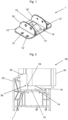
- a connector 1 according to a further embodiment of the present invention is shown in a perspective view.
- the connector 1 according to the invention comprises the connecting plate 10 into which frame holes 12, 12', 12" for fastening the connecting plate 10 to a frame profile 20 ( Fig. 5 ) are inserted.
- this connecting plate 10 With this connecting plate 10, in turn, an insertion element 14 in one piece.
- the insertion element 14 can also be inserted into a hollow chamber, preferably into the reinforcement chamber, of a post, transom or rung profile 30 ( Fig. 5 ) and thus contribute to the stability of a connection 40 according to the invention.
- the insertion element 14 corresponds to the insertion element 14 of the Fig. 1 connector 1 shown.
- the connector 1 shown is the contact elements 18, 18' of the Fig. 4
- the connector 1 shown is not rigidly connected to the connecting plate 10.
- two contact elements 18, 18' are also present. These are arranged at a distance from the insertion element 14.
- the contact elements 18, 18' are each connected to the connecting plate 10 so as to be rotatable about an axis, the axes of rotation of the contact elements 18, 18' each lying in the plane of the connecting plate 10.
- the axes of rotation run essentially parallel to the direction in which the post profile 30 is introduced into the frame formed from the frame profiles 20 during the production of the connection 40 according to the invention.
- the contact elements 18, 18' have a substantially L-shaped geometry, each with a large leg 19 and a small leg 19' arranged substantially perpendicularly thereto.
- the connecting plate 10 has recesses for receiving the small legs 19' when the contact elements 18, 18' are erected ( Fig. 5 ).
- the connector 1 is also in the Fig. 1 illustrated embodiment is manufactured as a cast part from an aluminum-zinc die-cast alloy, wherein the contact elements 18, 18', also manufactured as a cast part, are subsequently rotatably connected to the connecting plate 10.
- the contact elements 18, 18' can comprise at least one elevation, which can be designed as a dome, which engages in a corresponding recess, in particular a hole, of the post, transom or rung profile 30.
- the connector 12 according to the invention preferably comprises such elevations, which are each arranged on the large leg 19 of the contact elements 18, 18'. These elevations engage two recesses, which each are arranged on opposite profile walls of the post, transom or rung profile 30.
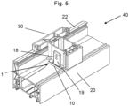
- the preparation of a compound 40 according to the invention is carried out in accordance with the procedure described with respect to the embodiment according to Fig. 1 to Fig. 3
- the post profile 30 engages the insertion element 14, the insertion element 14 presses in accordance with the procedure described in Fig. 4 and Fig. 5
- the post profile 30 is placed on the small legs 19' of the contact elements 18, 18'.
- the contact elements 18, 18' are raised until the large leg 19 of the contact elements 18, 18' rests against an outer wall of the post profile 30.
- the post profile 30 is pre-fixed in the connection 40 according to the invention.
- the final fixing of the connection 40 according to the invention by means of screws can now be carried out easily.
- the resulting connection 40 according to the invention is in Fig. 5 shown in a perspective view, whereby the screws used for final fixation are not shown.
Landscapes
- Engineering & Computer Science (AREA)
- Civil Engineering (AREA)
- Structural Engineering (AREA)
- Load-Bearing And Curtain Walls (AREA)
- Mutual Connection Of Rods And Tubes (AREA)
Claims (12)
- Connecteur (1) pour la connexion mécanique d'un profilé de cadre (20) avec un profilé de montant, de traverse ou de meneau (30) dans la construction de fenêtres et de portes, comprenant :une plaque de connexion (10) qui présente des trous de cadre (12) pour la fixation de la plaque de connexion (10) sur le profilé de cadre (20) ;au moins un élément d'insertion (14) destiné à être inséré dans une cavité du profilé de montant, de traverse ou de meneau (30), l'élément d'insertion (14) comprenant au moins un élément de transfert (16) destiné à faciliter le transfert du profilé de montant ou de meneau (30) sur l'élément d'insertion (14) ; etau moins un élément d'appui (18, 18') pour l'appui sur une paroi du profilé de montant ou de meneau (30),caractérisé en ce quel'au moins un élément d'appui (18, 18') est monté à rotation autour d'un axe.
- Connecteur (1) selon la revendication 1, caractérisé en ce que l'élément de transfert (16) est réalisé sous forme de plan incliné ou de pente d'introduction.
- Connecteur (1) selon la revendication 1 ou la revendication 2, caractérisé en ce que la plaque de connexion (10) et/ou l'élément d'insertion (14) présente en outre au moins un trou de serrage (15) dans lequel peut être vissée une vis de serrage pour serrer le connecteur (1) avec le profilé de cadre (20).
- Connecteur (1) selon l'une quelconque des revendications 1 à 3, caractérisé en ce que le connecteur est un composant fabriqué en aluminium, en acier inoxydable, en alliage d'aluminium coulé sous pression, en alliage de zinc coulé sous pression, en alliage d'aluminium et de zinc coulé sous pression, en acrylonitrile-styrène-ester acrylique (ASA), en polyamide (PA), en polyoxyméthylène (POM) ou en polymères renforcés par des fibres, notamment en polymères renforcés par des fibres de verre, ainsi qu'en mélanges des matériaux précités.
- Connecteur (1) selon l'une quelconque des revendications 1 à 4, caractérisé en ce que la hauteur de l'élément d'insertion (14) au-dessus de la plaque de connexion (10) se situe dans la plage allant de 5 % à 40 % de la largeur de la cavité du profilé de montant, de traverse ou de meneau (30) dans laquelle l'élément de pénétration (14) pénètre.
- Connecteur (1) selon l'une quelconque des revendications 1 à 5, caractérisé en ce que le côté (17) de l'élément d'insertion (14) opposé à l'au moins un élément de transfert (16) s'étend, au moins par sections, essentiellement parallèlement à une paroi de la cavité du profilé de montant, de traverse ou de meneau (30) dans laquelle l'élément d'insertion (14) peut être inséré.
- Connexion (40) entre un profilé de cadre (20) et un profilé de montant, de traverse ou de meneau (30) d'une fenêtre ou d'une porte, comprenant :- un profilé de cadre (20) ;- un profilé de montant, de traverse ou de meneau (30) ; et- un connecteur selon l'une quelconque des revendications 1 à 6.
- Connexion (40) selon la revendication 7, caractérisée en ce que le profilé de montant, de traverse ou de meneau (30) comprend, sur son côté tourné vers le connecteur (10) avant l'insertion du profilé de montant, de traverse ou de meneau (30) dans un cadre formé par le profilé de cadre (20), une aide à l'insertion (34).
- Connexion (40) selon la revendication 8, caractérisée en ce que l'aide à l'insertion (34) est réalisée sous forme d'aplatissement ou d'arrondissement d'un bord de profilé (36) du profilé de montant, de traverse ou de meneau (30).
- Connexion (40) selon l'une quelconque des revendications 7 à 9, caractérisée en ce que le côté (17) de l'élément d'insertion (14) opposé à l'au moins un élément de transfert (16) s'étend, au moins par sections, essentiellement parallèlement à une paroi de la cavité du profilé de montant, de traverse ou de meneau (30) dans laquelle l'élément d'insertion (14) est inséré.
- Connexion (40) selon l'une quelconque des revendications 7 à 10, caractérisée en ce que la connexion (40) comprend en outre des éléments de serrage pour connecter le profilé de cadre (20) ainsi que le profilé de montant, de traverse ou de meneau (30) au connecteur (10).
- Connexion (40) selon l'une quelconque des revendications 7 à 11, caractérisée en ce que l'au moins un élément d'appui (18, 18) comprend au moins une élévation, de préférence au moins un dôme, qui s'engage respectivement dans un évidement correspondant, notamment un trou, du profilé de montant, de traverse ou de meneau (30).
Applications Claiming Priority (1)
| Application Number | Priority Date | Filing Date | Title |
|---|---|---|---|
| DE202020107215.3U DE202020107215U1 (de) | 2020-12-14 | 2020-12-14 | Verbinder zur mechanischen Verbindung von Rahmenprofile mit Pfosten-, Kämpfer- oder Sprossenprofilen im Fenster- und Türenbau sowie diesen umfassende Verbindung |
Publications (2)
| Publication Number | Publication Date |
|---|---|
| EP4012148A1 EP4012148A1 (fr) | 2022-06-15 |
| EP4012148B1 true EP4012148B1 (fr) | 2024-10-30 |
Family
ID=78829337
Family Applications (1)
| Application Number | Title | Priority Date | Filing Date |
|---|---|---|---|
| EP21213661.8A Active EP4012148B1 (fr) | 2020-12-14 | 2021-12-10 | Connecteur pour la liaison mécanique de profilés de châssis pourvus de profilés de poteau, de traverse ou de montant dans la construction de fenêtre et de porte, ainsi que liaison comprenant ledit connecteur |
Country Status (2)
| Country | Link |
|---|---|
| EP (1) | EP4012148B1 (fr) |
| DE (1) | DE202020107215U1 (fr) |
Family Cites Families (8)
| Publication number | Priority date | Publication date | Assignee | Title |
|---|---|---|---|---|
| CH563536A5 (fr) * | 1973-05-15 | 1975-06-30 | Alusuisse | |
| DE3212436A1 (de) | 1982-04-02 | 1983-10-13 | Karlstadter Fenster- und Elementebau GmbH & Co KG, 8782 Karlstadt | Kaempferklotz |
| DE9400647U1 (de) | 1994-01-15 | 1994-04-14 | PaX GmbH, 55218 Ingelheim | Kämpferverbinder |
| GB9912337D0 (en) | 1999-05-26 | 1999-07-28 | Deceuninck Plastics Ind Nv | Mechanical joint |
| DE102011013138B3 (de) * | 2011-03-04 | 2012-09-13 | Hans Dieter Grotefeld | Vorrichtung zum Einsetzen eines Kämpfers in einen Tür- oder Fensterrahmen |
| DE202011005349U1 (de) * | 2011-04-15 | 2012-07-16 | Rehau Ag + Co | Verbinder zur Erzeugung einer Verbindung zwischen einem Rahmenprofil und einem Rahmen-, Kämpfer-, Pfosten- oder Sprossenprofil eines Fensters oder einer Tür und Verbindung, die einen derartigen Verbinder umfasst |
| DE202012008665U1 (de) | 2012-09-11 | 2012-10-26 | PHI Technik für Fenster und Türen GmbH | Anordnung zum Befestigen eines Pfostens an einer Rahmenleiste eines Fensters oder einer Türe mittels eines Pfostenverbinders |
| DE102013223968B4 (de) | 2013-11-22 | 2015-07-16 | PHI Technik für Fenster und Türen GmbH | Verbindungsanordnung zum Befestigen eines Pfostens an einem Rahmenträger eines Fensters, einer Türe oder dgl. aus Kunststoff |
-
2020
- 2020-12-14 DE DE202020107215.3U patent/DE202020107215U1/de active Active
-
2021
- 2021-12-10 EP EP21213661.8A patent/EP4012148B1/fr active Active
Also Published As
| Publication number | Publication date |
|---|---|
| EP4012148A1 (fr) | 2022-06-15 |
| DE202020107215U1 (de) | 2022-03-15 |
Similar Documents
| Publication | Publication Date | Title |
|---|---|---|
| DE2723850C2 (de) | Möbelscharnier | |
| DE2548527C3 (de) | Beschlag zum lösbaren Verbinden zweier senkrecht aufeinanderstoßender Bauteile | |
| EP1020575B1 (fr) | Connection en T entre un poteau et une traverse profilés d'une façade ou d'une toiture vitrée | |
| WO2013185747A2 (fr) | Support pour rail profilé | |
| EP2392761B1 (fr) | Système de cadre pour une grille de protection contre les insectes et/ou le pollen | |
| EP3124734B1 (fr) | Systeme de liaison destine a relier un jambage a un profil de cadre d'une fenetre ou d'une porte en matiere plastique | |
| DE9116873U1 (de) | Verbindungsvorrichtung für eine Sprossenkreuzkonstruktion | |
| EP4012148B1 (fr) | Connecteur pour la liaison mécanique de profilés de châssis pourvus de profilés de poteau, de traverse ou de montant dans la construction de fenêtre et de porte, ainsi que liaison comprenant ledit connecteur | |
| EP4012149B1 (fr) | Élément reliant destiné à la liaison mécanique des profilés de châssis pourvus de profilés de poteau, de traverse ou de montant dans la construction de fenêtre et de porte, ainsi que liaison comprenant ledit élément reliant | |
| DE102012011563A1 (de) | Halter für eine Profilschiene | |
| EP1035294B1 (fr) | Ensemble de montage d'un meneau dans un encadrement | |
| EP1915539B1 (fr) | Dispositif de raccordement basculant | |
| DE202011005349U1 (de) | Verbinder zur Erzeugung einer Verbindung zwischen einem Rahmenprofil und einem Rahmen-, Kämpfer-, Pfosten- oder Sprossenprofil eines Fensters oder einer Tür und Verbindung, die einen derartigen Verbinder umfasst | |
| DE202021106237U1 (de) | Verbindungsanordnung zum Verbinden eines Pfostens mit einem Rahmenprofil eines Fensters oder einer Türe aus Kunststoff | |
| DE3128023A1 (de) | "schraubzwinge" | |
| EP2679759B1 (fr) | Connecteur d'angle pour châssis en corps creux | |
| DE102017221802A1 (de) | Befestigungsklemme und Profilstabsystem | |
| DE102005053650B3 (de) | Scharnierbeschlag | |
| DE19940574C1 (de) | Anordnung zur Bildung einer Kreuzverbindung zwischen einem Längspfosten und einem Querpfosten bei einem Fenster oder einer Türe aus Kunststoff oder Leichtmetall | |
| EP2099989A2 (fr) | Crémone | |
| EP4015757A1 (fr) | Liaison entre un profilé de châssis et un profilé de poteau, de traverse ou de montant d'une fenêtre ou d'une porte, ainsi qu'élément reliant pour une telle liaison | |
| EP0291973A2 (fr) | Pièce de jonction de deux barres profilées aboutissant angulairement pour cadres de fenêtre ou porte | |
| DE9414631U1 (de) | Kunststoff-Hohlprofil | |
| EP3396098B1 (fr) | Élément de retenue pour rejet d'eau et son utilisation | |
| DE102009008380A1 (de) | T-Verbindung |
Legal Events
| Date | Code | Title | Description |
|---|---|---|---|
| PUAI | Public reference made under article 153(3) epc to a published international application that has entered the european phase |
Free format text: ORIGINAL CODE: 0009012 |
|
| STAA | Information on the status of an ep patent application or granted ep patent |
Free format text: STATUS: THE APPLICATION HAS BEEN PUBLISHED |
|
| AK | Designated contracting states |
Kind code of ref document: A1 Designated state(s): AL AT BE BG CH CY CZ DE DK EE ES FI FR GB GR HR HU IE IS IT LI LT LU LV MC MK MT NL NO PL PT RO RS SE SI SK SM TR |
|
| RAP3 | Party data changed (applicant data changed or rights of an application transferred) |
Owner name: REHAU INDUSTRIES SE & CO. KG |
|
| STAA | Information on the status of an ep patent application or granted ep patent |
Free format text: STATUS: REQUEST FOR EXAMINATION WAS MADE |
|
| 17P | Request for examination filed |
Effective date: 20221213 |
|
| RBV | Designated contracting states (corrected) |
Designated state(s): AL AT BE BG CH CY CZ DE DK EE ES FI FR GB GR HR HU IE IS IT LI LT LU LV MC MK MT NL NO PL PT RO RS SE SI SK SM TR |
|
| GRAP | Despatch of communication of intention to grant a patent |
Free format text: ORIGINAL CODE: EPIDOSNIGR1 |
|
| STAA | Information on the status of an ep patent application or granted ep patent |
Free format text: STATUS: GRANT OF PATENT IS INTENDED |
|
| INTG | Intention to grant announced |
Effective date: 20240531 |
|
| GRAS | Grant fee paid |
Free format text: ORIGINAL CODE: EPIDOSNIGR3 |
|
| GRAA | (expected) grant |
Free format text: ORIGINAL CODE: 0009210 |
|
| STAA | Information on the status of an ep patent application or granted ep patent |
Free format text: STATUS: THE PATENT HAS BEEN GRANTED |
|
| AK | Designated contracting states |
Kind code of ref document: B1 Designated state(s): AL AT BE BG CH CY CZ DE DK EE ES FI FR GB GR HR HU IE IS IT LI LT LU LV MC MK MT NL NO PL PT RO RS SE SI SK SM TR |
|
| REG | Reference to a national code |
Ref country code: GB Ref legal event code: FG4D Free format text: NOT ENGLISH |
|
| REG | Reference to a national code |
Ref country code: CH Ref legal event code: EP |
|
| REG | Reference to a national code |
Ref country code: IE Ref legal event code: FG4D Free format text: LANGUAGE OF EP DOCUMENT: GERMAN |
|
| REG | Reference to a national code |
Ref country code: DE Ref legal event code: R096 Ref document number: 502021005627 Country of ref document: DE |
|
| REG | Reference to a national code |
Ref country code: LT Ref legal event code: MG9D |
|
| REG | Reference to a national code |
Ref country code: NL Ref legal event code: MP Effective date: 20241030 |
|
| PG25 | Lapsed in a contracting state [announced via postgrant information from national office to epo] |
Ref country code: PT Free format text: LAPSE BECAUSE OF FAILURE TO SUBMIT A TRANSLATION OF THE DESCRIPTION OR TO PAY THE FEE WITHIN THE PRESCRIBED TIME-LIMIT Effective date: 20250228 Ref country code: HR Free format text: LAPSE BECAUSE OF FAILURE TO SUBMIT A TRANSLATION OF THE DESCRIPTION OR TO PAY THE FEE WITHIN THE PRESCRIBED TIME-LIMIT Effective date: 20241030 Ref country code: IS Free format text: LAPSE BECAUSE OF FAILURE TO SUBMIT A TRANSLATION OF THE DESCRIPTION OR TO PAY THE FEE WITHIN THE PRESCRIBED TIME-LIMIT Effective date: 20250228 |
|
| PG25 | Lapsed in a contracting state [announced via postgrant information from national office to epo] |
Ref country code: NL Free format text: LAPSE BECAUSE OF FAILURE TO SUBMIT A TRANSLATION OF THE DESCRIPTION OR TO PAY THE FEE WITHIN THE PRESCRIBED TIME-LIMIT Effective date: 20241030 Ref country code: FI Free format text: LAPSE BECAUSE OF FAILURE TO SUBMIT A TRANSLATION OF THE DESCRIPTION OR TO PAY THE FEE WITHIN THE PRESCRIBED TIME-LIMIT Effective date: 20241030 |
|
| PG25 | Lapsed in a contracting state [announced via postgrant information from national office to epo] |
Ref country code: BG Free format text: LAPSE BECAUSE OF FAILURE TO SUBMIT A TRANSLATION OF THE DESCRIPTION OR TO PAY THE FEE WITHIN THE PRESCRIBED TIME-LIMIT Effective date: 20241030 |
|
| PG25 | Lapsed in a contracting state [announced via postgrant information from national office to epo] |
Ref country code: ES Free format text: LAPSE BECAUSE OF FAILURE TO SUBMIT A TRANSLATION OF THE DESCRIPTION OR TO PAY THE FEE WITHIN THE PRESCRIBED TIME-LIMIT Effective date: 20241030 |
|
| PG25 | Lapsed in a contracting state [announced via postgrant information from national office to epo] |
Ref country code: NO Free format text: LAPSE BECAUSE OF FAILURE TO SUBMIT A TRANSLATION OF THE DESCRIPTION OR TO PAY THE FEE WITHIN THE PRESCRIBED TIME-LIMIT Effective date: 20250130 |
|
| PG25 | Lapsed in a contracting state [announced via postgrant information from national office to epo] |
Ref country code: LV Free format text: LAPSE BECAUSE OF FAILURE TO SUBMIT A TRANSLATION OF THE DESCRIPTION OR TO PAY THE FEE WITHIN THE PRESCRIBED TIME-LIMIT Effective date: 20241030 Ref country code: GR Free format text: LAPSE BECAUSE OF FAILURE TO SUBMIT A TRANSLATION OF THE DESCRIPTION OR TO PAY THE FEE WITHIN THE PRESCRIBED TIME-LIMIT Effective date: 20250131 |
|
| PG25 | Lapsed in a contracting state [announced via postgrant information from national office to epo] |
Ref country code: PL Free format text: LAPSE BECAUSE OF FAILURE TO SUBMIT A TRANSLATION OF THE DESCRIPTION OR TO PAY THE FEE WITHIN THE PRESCRIBED TIME-LIMIT Effective date: 20241030 |
|
| PG25 | Lapsed in a contracting state [announced via postgrant information from national office to epo] |
Ref country code: RS Free format text: LAPSE BECAUSE OF FAILURE TO SUBMIT A TRANSLATION OF THE DESCRIPTION OR TO PAY THE FEE WITHIN THE PRESCRIBED TIME-LIMIT Effective date: 20250130 |
|
| PG25 | Lapsed in a contracting state [announced via postgrant information from national office to epo] |
Ref country code: SM Free format text: LAPSE BECAUSE OF FAILURE TO SUBMIT A TRANSLATION OF THE DESCRIPTION OR TO PAY THE FEE WITHIN THE PRESCRIBED TIME-LIMIT Effective date: 20241030 |
|
| PG25 | Lapsed in a contracting state [announced via postgrant information from national office to epo] |
Ref country code: MC Free format text: LAPSE BECAUSE OF FAILURE TO SUBMIT A TRANSLATION OF THE DESCRIPTION OR TO PAY THE FEE WITHIN THE PRESCRIBED TIME-LIMIT Effective date: 20241030 |
|
| PG25 | Lapsed in a contracting state [announced via postgrant information from national office to epo] |
Ref country code: DK Free format text: LAPSE BECAUSE OF FAILURE TO SUBMIT A TRANSLATION OF THE DESCRIPTION OR TO PAY THE FEE WITHIN THE PRESCRIBED TIME-LIMIT Effective date: 20241030 |
|
| PG25 | Lapsed in a contracting state [announced via postgrant information from national office to epo] |
Ref country code: EE Free format text: LAPSE BECAUSE OF FAILURE TO SUBMIT A TRANSLATION OF THE DESCRIPTION OR TO PAY THE FEE WITHIN THE PRESCRIBED TIME-LIMIT Effective date: 20241030 |
|
| PG25 | Lapsed in a contracting state [announced via postgrant information from national office to epo] |
Ref country code: RO Free format text: LAPSE BECAUSE OF FAILURE TO SUBMIT A TRANSLATION OF THE DESCRIPTION OR TO PAY THE FEE WITHIN THE PRESCRIBED TIME-LIMIT Effective date: 20241030 |
|
| PG25 | Lapsed in a contracting state [announced via postgrant information from national office to epo] |
Ref country code: SK Free format text: LAPSE BECAUSE OF FAILURE TO SUBMIT A TRANSLATION OF THE DESCRIPTION OR TO PAY THE FEE WITHIN THE PRESCRIBED TIME-LIMIT Effective date: 20241030 |
|
| PG25 | Lapsed in a contracting state [announced via postgrant information from national office to epo] |
Ref country code: CZ Free format text: LAPSE BECAUSE OF FAILURE TO SUBMIT A TRANSLATION OF THE DESCRIPTION OR TO PAY THE FEE WITHIN THE PRESCRIBED TIME-LIMIT Effective date: 20241030 |
|
| PG25 | Lapsed in a contracting state [announced via postgrant information from national office to epo] |
Ref country code: IT Free format text: LAPSE BECAUSE OF FAILURE TO SUBMIT A TRANSLATION OF THE DESCRIPTION OR TO PAY THE FEE WITHIN THE PRESCRIBED TIME-LIMIT Effective date: 20241030 |
|
| REG | Reference to a national code |
Ref country code: DE Ref legal event code: R097 Ref document number: 502021005627 Country of ref document: DE |
|
| PLBE | No opposition filed within time limit |
Free format text: ORIGINAL CODE: 0009261 |
|
| STAA | Information on the status of an ep patent application or granted ep patent |
Free format text: STATUS: NO OPPOSITION FILED WITHIN TIME LIMIT |
|
| PG25 | Lapsed in a contracting state [announced via postgrant information from national office to epo] |
Ref country code: SE Free format text: LAPSE BECAUSE OF FAILURE TO SUBMIT A TRANSLATION OF THE DESCRIPTION OR TO PAY THE FEE WITHIN THE PRESCRIBED TIME-LIMIT Effective date: 20241030 |
|
| 26N | No opposition filed |
Effective date: 20250731 |
|
| REG | Reference to a national code |
Ref country code: CH Ref legal event code: U11 Free format text: ST27 STATUS EVENT CODE: U-0-0-U10-U11 (AS PROVIDED BY THE NATIONAL OFFICE) Effective date: 20260101 |
|
| PGFP | Annual fee paid to national office [announced via postgrant information from national office to epo] |
Ref country code: GB Payment date: 20251111 Year of fee payment: 5 |
|
| PGFP | Annual fee paid to national office [announced via postgrant information from national office to epo] |
Ref country code: AT Payment date: 20260113 Year of fee payment: 5 |
|
| PGFP | Annual fee paid to national office [announced via postgrant information from national office to epo] |
Ref country code: LU Payment date: 20251119 Year of fee payment: 5 Ref country code: FR Payment date: 20251125 Year of fee payment: 5 |
|
| PGFP | Annual fee paid to national office [announced via postgrant information from national office to epo] |
Ref country code: BE Payment date: 20251120 Year of fee payment: 5 |
|
| PGFP | Annual fee paid to national office [announced via postgrant information from national office to epo] |
Ref country code: IE Payment date: 20251120 Year of fee payment: 5 |
|
| PGFP | Annual fee paid to national office [announced via postgrant information from national office to epo] |
Ref country code: DE Payment date: 20251231 Year of fee payment: 5 |
|
| PGFP | Annual fee paid to national office [announced via postgrant information from national office to epo] |
Ref country code: CH Payment date: 20260101 Year of fee payment: 5 |