EP4012149B1 - Élément reliant destiné à la liaison mécanique des profilés de châssis pourvus de profilés de poteau, de traverse ou de montant dans la construction de fenêtre et de porte, ainsi que liaison comprenant ledit élément reliant - Google Patents
Élément reliant destiné à la liaison mécanique des profilés de châssis pourvus de profilés de poteau, de traverse ou de montant dans la construction de fenêtre et de porte, ainsi que liaison comprenant ledit élément reliant Download PDFInfo
- Publication number
- EP4012149B1 EP4012149B1 EP21213720.2A EP21213720A EP4012149B1 EP 4012149 B1 EP4012149 B1 EP 4012149B1 EP 21213720 A EP21213720 A EP 21213720A EP 4012149 B1 EP4012149 B1 EP 4012149B1
- Authority
- EP
- European Patent Office
- Prior art keywords
- profile
- transom
- connector
- mullion
- connection
- Prior art date
- Legal status (The legal status is an assumption and is not a legal conclusion. Google has not performed a legal analysis and makes no representation as to the accuracy of the status listed.)
- Active
Links
Images
Classifications
-
- E—FIXED CONSTRUCTIONS
- E06—DOORS, WINDOWS, SHUTTERS, OR ROLLER BLINDS IN GENERAL; LADDERS
- E06B—FIXED OR MOVABLE CLOSURES FOR OPENINGS IN BUILDINGS, VEHICLES, FENCES OR LIKE ENCLOSURES IN GENERAL, e.g. DOORS, WINDOWS, BLINDS, GATES
- E06B3/00—Window sashes, door leaves, or like elements for closing wall or like openings; Layout of fixed or moving closures, e.g. windows in wall or like openings; Features of rigidly-mounted outer frames relating to the mounting of wing frames
- E06B3/96—Corner joints or edge joints for windows, doors, or the like frames or wings
- E06B3/964—Corner joints or edge joints for windows, doors, or the like frames or wings using separate connection pieces, e.g. T-connection pieces
- E06B3/9642—Butt type joints with at least one frame member cut off square; T-shape joints
-
- E—FIXED CONSTRUCTIONS
- E06—DOORS, WINDOWS, SHUTTERS, OR ROLLER BLINDS IN GENERAL; LADDERS
- E06B—FIXED OR MOVABLE CLOSURES FOR OPENINGS IN BUILDINGS, VEHICLES, FENCES OR LIKE ENCLOSURES IN GENERAL, e.g. DOORS, WINDOWS, BLINDS, GATES
- E06B3/00—Window sashes, door leaves, or like elements for closing wall or like openings; Layout of fixed or moving closures, e.g. windows in wall or like openings; Features of rigidly-mounted outer frames relating to the mounting of wing frames
- E06B3/96—Corner joints or edge joints for windows, doors, or the like frames or wings
- E06B3/964—Corner joints or edge joints for windows, doors, or the like frames or wings using separate connection pieces, e.g. T-connection pieces
- E06B3/9641—Corner joints or edge joints for windows, doors, or the like frames or wings using separate connection pieces, e.g. T-connection pieces part of which remains visible
Definitions
- the present invention relates to a connector for mechanically connecting frame profiles with mullion, transom or muntin profiles in window and door construction, which comprises a connecting plate for resting on the frame profile and at least one contact element for resting on a wall of the mullion, transom or muntin profile.
- the present invention relates to a connection which comprises the connector according to the invention.
- a generic connector is from the DE 199 04 695 A1
- the connector disclosed therein is used to create a butt connection between a transom profile and a frame profile of a window or a door and has two spaced-apart contact elements that rest on two opposite sides of the transom profile and are fixed there to the transom profile.
- a disadvantage of the connector disclosed in the DE 199 04 695 A1 It can be seen from the connectors described that the manufacture of a transom connection comprising such a connector is difficult. In particular, it may be necessary to first attach the connector to the transom profile using the contact elements and then to insert it into the frame formed from the frame profile and fix it there, which means a considerable additional effort during assembly.
- Other connectors are known from the documents DE 10 2010 045809 A1 , DE 10 2007 053525 A1 , DE 20 2011 005349 U1 , US 2019/234064 A1 and GB 2 097 035 A known.
- the present invention is based on the object of providing a connector for mechanically connecting frame profiles to post, transom or muntin profiles in window and door construction, which overcomes the problems mentioned of prior art connectors, which can be manufactured inexpensively and is easy to install.
- the present invention provides a connection between a frame profile and a post, transom or muntin profile, which comprises such a connector.
- connection is made considerably easier if the contact elements are not rigidly connected to the connecting plate.
- the corresponding connector can then be connected in any case to the frame formed from the frame profile, a cut piece of the post, transom or muntin profile can be inserted into the frame and the contact elements can be cut to length and fixed to the wall of the post, transom or muntin profile after the post, transom or muntin profile has been inserted.
- this is achieved in that the contact elements are each designed to be movable about an axis. In this way, the assembly of such a connection is made considerably easier. This greatly simplifies the manufacture of a window that comprises a connection according to the invention.
- the present invention therefore relates to a connector for mechanically connecting a frame profile to a post, transom or muntin profile in window and door construction, wherein the connector comprises a connecting plate for resting on the frame profile and at least one contact element for contacting a wall of the post, transom or muntin profile, wherein the at least one contact element is designed to be movable about an axis and has a substantially L-shaped geometry, wherein the L-shaped geometry of the contact element(s) comprises a large leg and a small leg arranged substantially perpendicularly thereto, wherein the connector is characterized according to the invention in that the connecting plate has recesses for receiving the small legs.
- the present invention relates to a connection between a frame profile and a post, transom or muntin profile, wherein the connection comprises a frame profile, a post, transom or muntin profile and a connector according to the invention.
- the rotation axes of the contact elements preferably lie in the plane of the connecting plate. If a connector according to the invention has more than one rotation axis about which a contact element can be rotated, these rotation axes are preferably parallel to one another. In the case of an L-shaped cross-section of the contact element, the rotation axis about which this contact element can be rotated preferably lies in the straight section of the legs.
- the connector according to the invention has two contact elements, each of which is designed to be movable about an axis. Particularly preferably, these contact elements are arranged in such a way that In the finished connection according to the invention, they rest against two opposite walls of the post, transom or rung profile.
- the at least one contact element has a substantially L-shaped cross-section.
- the L-shaped cross-section of the contact element(s) according to the invention comprises a large leg and a small leg arranged substantially perpendicularly thereto. With such an L-shaped cross-section, the small leg can be easily accommodated in a corresponding recess in the connecting plate of the connector according to the invention. This increases the stability of the connection formed with the connector according to the invention.
- the connecting plate has recesses for accommodating the small legs. The number of recesses in the connecting plate preferably corresponds to the number of contact elements present in the connector.
- the connector according to the invention further comprises at least one insertion element for insertion into a hollow chamber of the post, transom or rung profile. Inserted into a hollow chamber, preferably into the reinforcement chamber, of the post, transom or rung profile, such an insertion element considerably increases the stability of the connection according to the invention comprising such a connector. Therefore, such an insertion element is often also referred to as a support body. It can be particularly helpful if the insertion element comprises at least one transfer element for easier transfer of the post, transom or rung profile over the insertion element.
- the connector When connecting the post, transom or rung profile to the frame profile, the connector is fixed to the frame profile and the post, transom or rung is inserted into the frame by sliding it onto the insertion element or the support body.
- the insertion element or the support body significantly simplifies the transfer of the post, transom or muntin profile over the insertion element.
- the cut piece of the post, transom or muntin profile can then be easily moved over the connector according to the invention using the transfer element, so that it is no longer necessary to spread the frame into which the post, transom or muntin is to be inserted.
- the transfer element is designed as an inclined plane or introduction slope.
- Such a design of the transfer element as an inclined plane or introduction slope on the connector according to the invention is particularly easy to implement.
- the purpose of the transfer element namely the insertion of a post, a transom or a rung into a frame without the need for tools, is made particularly easy.
- the side of the insertion element opposite the at least one transfer element runs, at least in sections, essentially parallel to a wall of the hollow chamber of the post, transom or rung profile into which the insertion element is to be inserted.
- This allows the piece of the post, transom or rung profile to snap behind the insertion element after being transferred over the insertion element of the connector according to the invention.
- This contributes significantly to the stability of the connection according to the invention.
- such a connection according to the invention is initially stable even before clamping, in particular screwing.
- the height of the penetration element above the connecting plate is in the range of 5% to 40% of the width of the hollow chamber of the post, transom or rung profile into which the penetration element penetrates.
- the height of the penetration element above the connecting plate is in the range of 10% to 25% of the width of the hollow chamber of the post, transom or rung profile into which the penetration element penetrates.
- the connecting plate and/or the penetration element additionally has at least one bracing hole into which a clamping screw can be screwed in order to brace the connecting plate to the frame profile. This ensures a particularly stable connection of the connector according to the invention to the frame profile.
- the connector according to the invention is a component made of aluminum, stainless steel, an aluminum die-casting alloy, a zinc die-casting alloy, an aluminum-zinc die-casting alloy, acrylonitrile-styrene-acrylate (ASA), polyamide (PA), polyoxymethylene (POM) or fiber-reinforced polymers, in particular glass fiber-reinforced polymers, as well as mixtures of the aforementioned Materials.
- ASA acrylonitrile-styrene-acrylate
- PA polyamide
- POM polyoxymethylene
- fiber-reinforced polymers in particular glass fiber-reinforced polymers, as well as mixtures of the aforementioned Materials.
- different sections or areas of the connector according to the invention can be made of different materials. The materials mentioned have proven to be particularly suitable, with a component made of an aluminum-zinc die-cast alloy in particular proving to be particularly resistant.
- the connecting plate of the connector according to the invention is made of metal, preferably of zinc or a zinc die
- the insertion element or the support body has at least one elevation protruding away from it on the side facing the frame profile. This can ensure that when the connection is created between the connector and the frame profile, the elevations are pressed into the frame profile, thereby creating a positive connection in addition to the surface connection between the connector and the frame profile. It can be particularly advantageous if the elevation protrudes conically from the insertion element. The conical shape of the elevation promotes the penetration of the elevation into the frame profile. In this regard, it can prove particularly advantageous if the material of the insertion element on the side facing the frame profile, which has the elevations protruding from the insertion element, consists of a harder material than the material of the frame profile. This further promotes the penetration of the elevations into the frame profile and thus the positive connection between the connector and the frame profile.
- the connecting plate of the connector according to the invention comprises a sealing element on its side facing away from the inserted element.
- This sealing element can preferably be designed as an adhesive-bonded sealing cushion, in particular made of EPDM cellular rubber or PE.
- an overmolded TPE can also be used for sealing.
- the post, transom or rafter profile comprises an insertion aid on its side facing the connector before the post, transom or rafter profile is inserted into a frame formed from the frame profile.
- This also makes the production of the connection according to the invention considerably easier because the post, transom or rafter profile can be guided even more easily over the insertion element.
- the insertion aid is designed as a flattening or rounding of a profile edge of the post, transom or rung profile.
- connection further comprises clamping elements, in particular screws, for connecting the frame profile and the post, transom or rung profile to the connector.
- clamping elements serve to finally fix the connection according to the invention.
- the at least one contact element of the connector according to the invention comprises at least one elevation, which engages in a corresponding recess, in particular a hole, in the post, transom or rung profile.
- the elevation is designed in the form of a dome.
- the elevation or dome is preferably formed on the large leg of the L-shaped contact elements.
- the frame profile is a hollow chamber profile comprising a plurality of hollow chambers, in particular a plastic hollow profile chamber profile comprising a plurality of hollow chambers and thus, in the case of a window, it is a plastic window and in the case of a door, it is a plastic door.
- the connector according to the invention, the connection according to the invention and individual parts thereof can also be manufactured line by line or layer by layer using a line-building or layer-building manufacturing process (e.g. 3D printing), but the connector according to the invention is preferably manufactured by injection molding and the profiles further involved in the connection according to the invention are manufactured by extrusion.
- a line-building or layer-building manufacturing process e.g. 3D printing
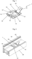
- a connector 1 according to an embodiment of the present invention is shown in a perspective view.
- the connector 1 according to the invention comprises a connecting plate 10 into which frame holes 12, 12', 12" are drilled for fastening the connecting plate 10 to a frame profile 20 ( Fig. 2 ) are inserted.
- An insertion element 14 is connected in one piece to this connecting plate 10.
- the insertion element 14 is intended to be inserted into a hollow chamber, preferably into the reinforcement chamber, of a post, transom or rung profile 30 ( Fig. 3 ) and thus contribute to the stability of a connection 40 according to the invention.
- the insertion element 14 is relatively flat. Its height in the Fig.
- the post, transom or rung profile 30 can be moved more easily over the insertion element 14 when producing the connection 10 according to the invention and can thus be placed on the connector 1 according to the invention.
- the insertion element 14 has an inclined plane sloping towards the outside of the connector 1 according to the invention. This inclined plane serves to facilitate the transfer of the post, transom or rung profile 30 over the insertion element 14.
- the inclined plane thus functions as a transfer element 16 for the easier transfer of the post, transom or rung profile 30 over the insertion element 14.
- the insertion element 14 On its upper side, the insertion element 14 has a clamping hole 15. A clamping element, in particular a clamping screw, can be guided through this clamping hole, which serves to clamp the connector according to the invention to the frame profile 20.
- the side of the insertion element 14 opposite the transfer element 16 is in the Fig. 1 illustrated embodiments are essentially orthogonal to the connecting plate.
- the connector according to the invention comprises two contact elements 18, 18'.
- the contact elements 18, 18' rest against two opposite outer walls of the post, transom or rung profile 30.
- the contact elements 18, 18' also have holes for the passage of clamping elements for securing the connector 1 according to the invention to the post, transom or rung profile 30.
- the contact elements 18, 18' of the Fig. 1 are not rigidly connected to the connecting plate 10.
- the contact elements 18, 18' are each connected to the connecting plate 10 so as to be rotatable about an axis, whereby the axes of rotation of the contact elements 18, 18' are each located in the plane of the connecting plate 10.
- the axes of rotation of the contact elements 18, 18' are aligned parallel to one another.
- the axes of rotation run essentially parallel to the direction in which the post profile 30 is introduced into the frame formed from the frame profiles 20 during the production of the connection 40 according to the invention.
- the contact elements 18, 18' have a substantially L-shaped cross-section, each with a large leg 19 and a small leg 19' arranged substantially perpendicularly thereto.
- the connecting plate 10 has recesses for receiving the small legs 19' when the contact elements 18, 18' are erected ( Fig. 3 ).
- the axes of rotation about which the contact elements 18, 18' can be pivoted lie in the intersection lines of the two legs 19, 19'.
- the connector 1 according to the invention is in the Fig. 1 illustrated embodiment is manufactured as a cast part from an aluminum-zinc die-cast alloy, wherein the contact elements 18, 18', also manufactured as a cast part, are subsequently connected to the connecting plate 10 from an aluminum-zinc die-cast alloy so as to be rotatable about the respective axis.
- the contact elements 18, 18' can comprise at least one elevation, which can be designed as a dome, which engages in a corresponding recess, in particular a hole, in the post, transom or rung profile 30.
- the connector 12 according to the invention preferably comprises such elevations, which are each arranged on the large leg 19 of the contact elements 18, 18'. These elevations engage two recesses, which are each arranged on opposite profile walls of the post, transom or rung profile 30.
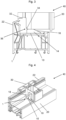
- connection 40 the connector 1 according to the invention is placed on the frame profile 20 at the appropriate position, which is Fig. 2 shown in a perspective view, and fixed in this position by means of clamping elements (not shown), in particular by means of screws which are guided through the frame holes 12, 12', 12".
- the connecting plate 10 is adapted to the geometry of the fold of the frame profile 20 on its underside facing the frame profile 20 ( Fig. 3 ).
- a piece of a post profile 30 is then inserted into a frame formed from the frame profiles 20. To do this, a piece of a suitable length is first cut from a bar of the post profile 30.
- a recess 32 is made in the post profile 30 so that the contour of the post profile 30 is adapted to an overlap 22 of the frame profile 30, which in Fig. 3 can be clearly seen in which a cross-sectional view of a connection 40 according to the invention with the Fig. 1
- an insertion aid 34 is added to the post profile 30 at this end. In the embodiment shown in Fig. 3 In the embodiment shown, this is done by removing material from the post profile 30.
- the insertion aid 34 is designed in the embodiment shown as a rounded section of a profile edge 36 of the post profile 30. Alternatively, a bevel of the profile edge 36 is also conceivable.
- the insertion aid 34 designed as a rounded section allows the end of the post profile 30 to be easily pushed along the insertion element 14 of the connector 1 according to the invention. Pushing the post profile 30 further in the direction of the overlap 22 of the frame profile 20 results in the overlap 22 being recessed in the milled recess 32 of the post profile 30 and the insertion element 14 being received in a hollow chamber of the post profile 30. Since the side of the insertion element 14 opposite the transfer element 16 is parallel to the corresponding wall of the hollow chamber of the post profile 30, the post profile 30 engages the insertion element 14 so that the connection 40 according to the invention is pre-fixed. In the embodiment of the present invention shown, the post profile 30 presses on the small legs 19' of the contact elements 18, 18'.
- connection elements 18, 18' straighten up until the large leg 19 of the contact elements 18, 18' rests on an outer wall of the post profile 30.
- the respective small legs 19' are received in the corresponding recesses of the connection plate 10.
- the post profile 30 is pre-fixed in the connection 40 according to the invention.
- the final fixing of the connection 40 according to the invention by means of screws can now be carried out easily.
- the resulting connection 40 according to the invention is in Fig. 4 shown in a perspective view, whereby the screws used for final fixation are not shown.
Landscapes
- Engineering & Computer Science (AREA)
- Civil Engineering (AREA)
- Structural Engineering (AREA)
- Load-Bearing And Curtain Walls (AREA)
- Mutual Connection Of Rods And Tubes (AREA)
Claims (12)
- Connecteur (1) pour la connexion mécanique d'un profilé de cadre (20) avec un profilé de montant, de traverse ou de meneau (30) dans la construction de fenêtres et de portes, comprenant :une plaque de connexion (10) destinée à reposer sur le profilé de cadre (20) ; etau moins un élément d'appui (18, 18') pour l'appui sur une paroi du profilé de montant, de traverse ou de meneau (30), l'au moins un élément d'appui (18, 18') étant réalisé sous forme mobile autour d'un axe et présentant une géométrie essentiellement en forme de L, la géométrie en forme de L de l'élément d'appui/des éléments d'appui (18, 18') comprenant une grande branche (19) et une petite branche (19') agencée essentiellement perpendiculairement à celle-ci,caractérisé en ce quela plaque de connexion (10) présente des évidements destinés à recevoir les petites branches (19').
- Connecteur (1) selon la revendication 1, caractérisé en ce que le connecteur (1) comprend en outre au moins un élément d'insertion (14) destiné à être inséré dans une cavité du profilé de montant, de traverse ou de meneau (30).
- Connecteur (1) selon la revendication 1 ou la revendication 2, caractérisé en ce que l'élément d'insertion (14) comprend au moins un élément de transfert (16) destiné à faciliter le transfert du profilé de montant, de traverse ou de meneau (30) sur l'élément d'insertion (14), l'élément de transfert (16) étant de préférence réalisé sous forme de plan incliné ou de pente d'introduction.
- Connecteur (1) selon la revendication 3, caractérisé en ce que le côté (17) de l'élément d'insertion (14) opposé à l'au moins un élément de transfert (16) s'étend, au moins par sections, essentiellement parallèlement à une paroi de la cavité du profilé de montant, de traverse ou de meneau (30), dans laquelle l'élément d'insertion (14) peut être inséré.
- Connecteur (1) selon l'une quelconque des revendications 2 à 4, caractérisé en ce que la hauteur de l'élément d'insertion (14) au-dessus de la plaque de connexion (10) se situe dans la plage allant de 5 % à 40 % de la largeur de la cavité du profilé de cadre (20) dans laquelle l'élément de pénétration (14) pénètre.
- Connecteur (1) selon l'une quelconque des revendications 1 à 5, caractérisé en ce que la plaque de connexion (10) et/ou l'élément de pénétration (14) présente en outre au moins un trou de serrage (15) dans lequel peut être vissée une vis de serrage pour serrer le connecteur (1) avec le profilé de cadre (20).
- Connecteur (1) selon l'une quelconque des revendications 1 à 6, caractérisé en ce que le connecteur est un composant fabriqué en aluminium, en acier inoxydable, en alliage d'aluminium coulé sous pression, en alliage de zinc coulé sous pression, en alliage d'aluminium et de zinc coulé sous pression, en acrylonitrile-styrène-ester acrylique (ASA), en polyamide (PA), en polyoxyméthylène (POM) ou en polymères renforcés par des fibres, notamment en polymères renforcés par des fibres de verre, ainsi qu'en mélanges des matériaux précités.
- Connexion (40) entre un profilé de cadre (20) et un profilé de montant, de traverse ou de meneau (30) d'une fenêtre ou d'une porte, comprenant :- un profilé de cadre (20) ;- un profilé de montant, de traverse ou de meneau (30) ; et- un connecteur selon l'une quelconque des revendications 1 à 7.
- Connexion (40) selon la revendication 8, caractérisée en ce que le profilé de montant, de traverse ou de meneau (30) comprend, sur son côté tourné vers le connecteur (10) avant l'insertion du profilé de montant, de traverse ou de meneau (30) dans un cadre formé par le profilé de cadre (20), une aide à l'insertion (34), l'aide à l'insertion (34) étant de préférence réalisée sous forme d'aplatissement ou d'arrondissement d'un bord de profilé (36) du profilé de montant, de traverse ou de meneau (30).
- Connexion (40) selon la revendication 8 ou la revendication 9, caractérisée en ce que le côté (17) de l'élément d'insertion (14) opposé à l'au moins un élément de transfert (16) s'étend, au moins par sections, essentiellement parallèlement à une paroi de la cavité du profilé de montant, de traverse ou de meneau (30) dans laquelle l'élément d'insertion (14) est inséré.
- Connexion (40) selon l'une quelconque des revendications 8 à 10, caractérisée en ce que la connexion (40) comprend en outre des éléments de serrage pour connecter le profilé de cadre (20) ainsi que le profilé de montant, de traverse ou de meneau (30) au connecteur (10).
- Connexion (40) selon l'une quelconque des revendications 8 à 11, caractérisée en ce que l'au moins un élément d'appui (18, 18) comprend au moins une élévation, de préférence au moins un dôme, qui s'engage respectivement dans un évidement correspondant, notamment un trou, du profilé de montant, de traverse ou de meneau (30).
Applications Claiming Priority (1)
| Application Number | Priority Date | Filing Date | Title |
|---|---|---|---|
| DE202020107218.8U DE202020107218U1 (de) | 2020-12-14 | 2020-12-14 | Verbinder zur mechanischen Verbindung von Rahmenprofilen mit Pfosten-, Kämpfer- oder Sprossenprofilen im Fenster- und Türenbau sowie diesen umfassende Verbindung |
Publications (3)
| Publication Number | Publication Date |
|---|---|
| EP4012149A1 EP4012149A1 (fr) | 2022-06-15 |
| EP4012149C0 EP4012149C0 (fr) | 2024-11-06 |
| EP4012149B1 true EP4012149B1 (fr) | 2024-11-06 |
Family
ID=78829362
Family Applications (1)
| Application Number | Title | Priority Date | Filing Date |
|---|---|---|---|
| EP21213720.2A Active EP4012149B1 (fr) | 2020-12-14 | 2021-12-10 | Élément reliant destiné à la liaison mécanique des profilés de châssis pourvus de profilés de poteau, de traverse ou de montant dans la construction de fenêtre et de porte, ainsi que liaison comprenant ledit élément reliant |
Country Status (2)
| Country | Link |
|---|---|
| EP (1) | EP4012149B1 (fr) |
| DE (1) | DE202020107218U1 (fr) |
Family Cites Families (11)
| Publication number | Priority date | Publication date | Assignee | Title |
|---|---|---|---|---|
| GB2097035A (en) * | 1981-01-21 | 1982-10-27 | Levin Ezra | Concealed resilient fasteners for fastening panels to frames |
| DE9406655U1 (de) | 1994-04-21 | 1994-06-30 | MFT GmbH - Moderne Fenster Technik -, 26871 Papenburg | Verbindungsstück für winklig aneinanderstoßende Hohlprofilstäbe |
| DE19904695A1 (de) | 1998-02-05 | 1999-08-26 | Veka Ag | Kämpferverbinder |
| GB9912337D0 (en) * | 1999-05-26 | 1999-07-28 | Deceuninck Plastics Ind Nv | Mechanical joint |
| DE102007053525A1 (de) | 2007-11-09 | 2009-06-10 | Inoutic / Deceuninck Gmbh | Schwellenverbinder |
| DE102010045809B4 (de) * | 2010-09-20 | 2015-11-26 | Hans Dieter Grotefeld | Vorrichtung zum Einsetzen eines Kämpfers in einen Tür- oder Fensterrahmen |
| DE202011005349U1 (de) | 2011-04-15 | 2012-07-16 | Rehau Ag + Co | Verbinder zur Erzeugung einer Verbindung zwischen einem Rahmenprofil und einem Rahmen-, Kämpfer-, Pfosten- oder Sprossenprofil eines Fensters oder einer Tür und Verbindung, die einen derartigen Verbinder umfasst |
| DE202016102786U1 (de) | 2016-05-25 | 2017-08-28 | Rehau Ag + Co | Türrahmenverbindung und Schwellenhalter zur Verwendung in einer derartigen Türrahmenverbindung |
| DE102016123889A1 (de) | 2016-12-08 | 2018-06-14 | PHI Technik für Fenster und Türen GmbH | Verbindungsanordnung zum Verbinden eines Pfostens mit einem Rahmenprofil eines Fensters oder einer Türe aus Kunststoff |
| AU2019212717B2 (en) * | 2018-01-26 | 2024-12-19 | Simpson Strong-Tie Company Inc. | Hinged connector |
| DE102019108526A1 (de) | 2019-04-02 | 2020-10-08 | Profine Gmbh | T-Verbinder, insbesondere Sprossenverbinder, für geklebte Verglasungen |
-
2020
- 2020-12-14 DE DE202020107218.8U patent/DE202020107218U1/de active Active
-
2021
- 2021-12-10 EP EP21213720.2A patent/EP4012149B1/fr active Active
Also Published As
| Publication number | Publication date |
|---|---|
| EP4012149A1 (fr) | 2022-06-15 |
| EP4012149C0 (fr) | 2024-11-06 |
| DE202020107218U1 (de) | 2022-03-15 |
Similar Documents
| Publication | Publication Date | Title |
|---|---|---|
| WO2013185747A2 (fr) | Support pour rail profilé | |
| DE10016608A1 (de) | Spannglied zum stirnseitigen Verbinden von Profilstäben | |
| EP2868856B1 (fr) | Raccord d'angle destiné à relier des profilés creux coupés en onglet d'un cadre de porte ou de fenêtre | |
| EP3124734B1 (fr) | Systeme de liaison destine a relier un jambage a un profil de cadre d'une fenetre ou d'une porte en matiere plastique | |
| DE9116873U1 (de) | Verbindungsvorrichtung für eine Sprossenkreuzkonstruktion | |
| EP3283776B1 (fr) | Cheville à bascule | |
| EP4012149B1 (fr) | Élément reliant destiné à la liaison mécanique des profilés de châssis pourvus de profilés de poteau, de traverse ou de montant dans la construction de fenêtre et de porte, ainsi que liaison comprenant ledit élément reliant | |
| EP4012148B1 (fr) | Connecteur pour la liaison mécanique de profilés de châssis pourvus de profilés de poteau, de traverse ou de montant dans la construction de fenêtre et de porte, ainsi que liaison comprenant ledit connecteur | |
| EP2754803B1 (fr) | Crémone de fenêtre ou de porte et tringle pour une telle crémone | |
| EP0539672A1 (fr) | Ferrure pour fixation dans une rainure d'un profilé rétréci des deux côtés | |
| EP4015757B1 (fr) | Liaison entre un profilé de châssis et un profilé de poteau, de traverse ou de montant d'une fenêtre ou d'une porte | |
| DE19752619A1 (de) | Verbindungsbauteil für eine Fassadenkonstruktion und Fassadenkonstruktion | |
| EP0291973B1 (fr) | Pièce de jonction de deux barres profilées aboutissant angulairement pour cadres de fenêtre ou porte | |
| DE102017221802A1 (de) | Befestigungsklemme und Profilstabsystem | |
| DE102005053650B3 (de) | Scharnierbeschlag | |
| DE19940574C1 (de) | Anordnung zur Bildung einer Kreuzverbindung zwischen einem Längspfosten und einem Querpfosten bei einem Fenster oder einer Türe aus Kunststoff oder Leichtmetall | |
| DE202007015356U1 (de) | Mechanischer Verbinder | |
| EP2099989A2 (fr) | Crémone | |
| DE3002198C2 (de) | Halter für ein im Querschnitt etwa umgekehrt U-förmiges Mauerabdeckprofil | |
| DE102022102935B4 (de) | Verbindungsanordnung zum Verbinden eines Pfostens mit einem Rahmenprofil eines Fensters oder einer Türe aus Kunststoff | |
| EP2620579A2 (fr) | Elément de liaison destiné à la liaison de pièces profilées | |
| EP2530336B1 (fr) | Dispositif de soutien de composants | |
| EP0808968A1 (fr) | Connecteur pour grilles et pince de sertissage adaptée | |
| EP3408467B1 (fr) | Branche de profilé et profilé d'arête pour enduits | |
| DE19914638C1 (de) | Verbindungsanordnung |
Legal Events
| Date | Code | Title | Description |
|---|---|---|---|
| PUAI | Public reference made under article 153(3) epc to a published international application that has entered the european phase |
Free format text: ORIGINAL CODE: 0009012 |
|
| STAA | Information on the status of an ep patent application or granted ep patent |
Free format text: STATUS: THE APPLICATION HAS BEEN PUBLISHED |
|
| AK | Designated contracting states |
Kind code of ref document: A1 Designated state(s): AL AT BE BG CH CY CZ DE DK EE ES FI FR GB GR HR HU IE IS IT LI LT LU LV MC MK MT NL NO PL PT RO RS SE SI SK SM TR |
|
| RAP3 | Party data changed (applicant data changed or rights of an application transferred) |
Owner name: REHAU INDUSTRIES SE & CO. KG |
|
| STAA | Information on the status of an ep patent application or granted ep patent |
Free format text: STATUS: REQUEST FOR EXAMINATION WAS MADE |
|
| 17P | Request for examination filed |
Effective date: 20221213 |
|
| RBV | Designated contracting states (corrected) |
Designated state(s): AL AT BE BG CH CY CZ DE DK EE ES FI FR GB GR HR HU IE IS IT LI LT LU LV MC MK MT NL NO PL PT RO RS SE SI SK SM TR |
|
| GRAP | Despatch of communication of intention to grant a patent |
Free format text: ORIGINAL CODE: EPIDOSNIGR1 |
|
| STAA | Information on the status of an ep patent application or granted ep patent |
Free format text: STATUS: GRANT OF PATENT IS INTENDED |
|
| INTG | Intention to grant announced |
Effective date: 20240531 |
|
| GRAS | Grant fee paid |
Free format text: ORIGINAL CODE: EPIDOSNIGR3 |
|
| GRAA | (expected) grant |
Free format text: ORIGINAL CODE: 0009210 |
|
| STAA | Information on the status of an ep patent application or granted ep patent |
Free format text: STATUS: THE PATENT HAS BEEN GRANTED |
|
| AK | Designated contracting states |
Kind code of ref document: B1 Designated state(s): AL AT BE BG CH CY CZ DE DK EE ES FI FR GB GR HR HU IE IS IT LI LT LU LV MC MK MT NL NO PL PT RO RS SE SI SK SM TR |
|
| REG | Reference to a national code |
Ref country code: GB Ref legal event code: FG4D Free format text: NOT ENGLISH |
|
| REG | Reference to a national code |
Ref country code: CH Ref legal event code: EP |
|
| REG | Reference to a national code |
Ref country code: DE Ref legal event code: R096 Ref document number: 502021005717 Country of ref document: DE |
|
| REG | Reference to a national code |
Ref country code: IE Ref legal event code: FG4D Free format text: LANGUAGE OF EP DOCUMENT: GERMAN |
|
| U01 | Request for unitary effect filed |
Effective date: 20241205 |
|
| U07 | Unitary effect registered |
Designated state(s): AT BE BG DE DK EE FI FR IT LT LU LV MT NL PT RO SE SI Effective date: 20250117 |
|
| U20 | Renewal fee for the european patent with unitary effect paid |
Year of fee payment: 4 Effective date: 20250117 |
|
| PG25 | Lapsed in a contracting state [announced via postgrant information from national office to epo] |
Ref country code: HR Free format text: LAPSE BECAUSE OF FAILURE TO SUBMIT A TRANSLATION OF THE DESCRIPTION OR TO PAY THE FEE WITHIN THE PRESCRIBED TIME-LIMIT Effective date: 20241106 Ref country code: IS Free format text: LAPSE BECAUSE OF FAILURE TO SUBMIT A TRANSLATION OF THE DESCRIPTION OR TO PAY THE FEE WITHIN THE PRESCRIBED TIME-LIMIT Effective date: 20250306 |
|
| PG25 | Lapsed in a contracting state [announced via postgrant information from national office to epo] |
Ref country code: ES Free format text: LAPSE BECAUSE OF FAILURE TO SUBMIT A TRANSLATION OF THE DESCRIPTION OR TO PAY THE FEE WITHIN THE PRESCRIBED TIME-LIMIT Effective date: 20241106 |
|
| PG25 | Lapsed in a contracting state [announced via postgrant information from national office to epo] |
Ref country code: NO Free format text: LAPSE BECAUSE OF FAILURE TO SUBMIT A TRANSLATION OF THE DESCRIPTION OR TO PAY THE FEE WITHIN THE PRESCRIBED TIME-LIMIT Effective date: 20250206 |
|
| PG25 | Lapsed in a contracting state [announced via postgrant information from national office to epo] |
Ref country code: GR Free format text: LAPSE BECAUSE OF FAILURE TO SUBMIT A TRANSLATION OF THE DESCRIPTION OR TO PAY THE FEE WITHIN THE PRESCRIBED TIME-LIMIT Effective date: 20250207 |
|
| PG25 | Lapsed in a contracting state [announced via postgrant information from national office to epo] |
Ref country code: PL Free format text: LAPSE BECAUSE OF FAILURE TO SUBMIT A TRANSLATION OF THE DESCRIPTION OR TO PAY THE FEE WITHIN THE PRESCRIBED TIME-LIMIT Effective date: 20241106 |
|
| PG25 | Lapsed in a contracting state [announced via postgrant information from national office to epo] |
Ref country code: RS Free format text: LAPSE BECAUSE OF FAILURE TO SUBMIT A TRANSLATION OF THE DESCRIPTION OR TO PAY THE FEE WITHIN THE PRESCRIBED TIME-LIMIT Effective date: 20250206 |
|
| PG25 | Lapsed in a contracting state [announced via postgrant information from national office to epo] |
Ref country code: SM Free format text: LAPSE BECAUSE OF FAILURE TO SUBMIT A TRANSLATION OF THE DESCRIPTION OR TO PAY THE FEE WITHIN THE PRESCRIBED TIME-LIMIT Effective date: 20241106 |
|
| PG25 | Lapsed in a contracting state [announced via postgrant information from national office to epo] |
Ref country code: SK Free format text: LAPSE BECAUSE OF FAILURE TO SUBMIT A TRANSLATION OF THE DESCRIPTION OR TO PAY THE FEE WITHIN THE PRESCRIBED TIME-LIMIT Effective date: 20241106 |
|
| PG25 | Lapsed in a contracting state [announced via postgrant information from national office to epo] |
Ref country code: CZ Free format text: LAPSE BECAUSE OF FAILURE TO SUBMIT A TRANSLATION OF THE DESCRIPTION OR TO PAY THE FEE WITHIN THE PRESCRIBED TIME-LIMIT Effective date: 20241106 |
|
| REG | Reference to a national code |
Ref country code: CH Ref legal event code: PL |
|
| PLBE | No opposition filed within time limit |
Free format text: ORIGINAL CODE: 0009261 |
|
| STAA | Information on the status of an ep patent application or granted ep patent |
Free format text: STATUS: NO OPPOSITION FILED WITHIN TIME LIMIT |
|
| PG25 | Lapsed in a contracting state [announced via postgrant information from national office to epo] |
Ref country code: MC Free format text: LAPSE BECAUSE OF FAILURE TO SUBMIT A TRANSLATION OF THE DESCRIPTION OR TO PAY THE FEE WITHIN THE PRESCRIBED TIME-LIMIT Effective date: 20241106 |
|
| 26N | No opposition filed |
Effective date: 20250807 |
|
| PG25 | Lapsed in a contracting state [announced via postgrant information from national office to epo] |
Ref country code: CH Free format text: LAPSE BECAUSE OF NON-PAYMENT OF DUE FEES Effective date: 20241231 |
|
| PG25 | Lapsed in a contracting state [announced via postgrant information from national office to epo] |
Ref country code: IE Free format text: LAPSE BECAUSE OF NON-PAYMENT OF DUE FEES Effective date: 20241210 |
|
| U20 | Renewal fee for the european patent with unitary effect paid |
Year of fee payment: 5 Effective date: 20251125 |