EP4012189A1 - Élément de conduit d'air pour roue à écoulement transversal, et dispositif de climatisation le comprenant - Google Patents
Élément de conduit d'air pour roue à écoulement transversal, et dispositif de climatisation le comprenant Download PDFInfo
- Publication number
- EP4012189A1 EP4012189A1 EP20914785.9A EP20914785A EP4012189A1 EP 4012189 A1 EP4012189 A1 EP 4012189A1 EP 20914785 A EP20914785 A EP 20914785A EP 4012189 A1 EP4012189 A1 EP 4012189A1
- Authority
- EP
- European Patent Office
- Prior art keywords
- section
- cross
- air duct
- volute
- flow impeller
- Prior art date
- Legal status (The legal status is an assumption and is not a legal conclusion. Google has not performed a legal analysis and makes no representation as to the accuracy of the status listed.)
- Granted
Links
Images




Classifications
-
- F—MECHANICAL ENGINEERING; LIGHTING; HEATING; WEAPONS; BLASTING
- F04—POSITIVE - DISPLACEMENT MACHINES FOR LIQUIDS; PUMPS FOR LIQUIDS OR ELASTIC FLUIDS
- F04D—NON-POSITIVE-DISPLACEMENT PUMPS
- F04D17/00—Radial-flow pumps, e.g. centrifugal pumps; Helico-centrifugal pumps
- F04D17/02—Radial-flow pumps, e.g. centrifugal pumps; Helico-centrifugal pumps having non-centrifugal stages, e.g. centripetal
- F04D17/04—Radial-flow pumps, e.g. centrifugal pumps; Helico-centrifugal pumps having non-centrifugal stages, e.g. centripetal of transverse-flow type
-
- F—MECHANICAL ENGINEERING; LIGHTING; HEATING; WEAPONS; BLASTING
- F04—POSITIVE - DISPLACEMENT MACHINES FOR LIQUIDS; PUMPS FOR LIQUIDS OR ELASTIC FLUIDS
- F04D—NON-POSITIVE-DISPLACEMENT PUMPS
- F04D25/00—Pumping installations or systems
- F04D25/02—Units comprising pumps and their driving means
- F04D25/08—Units comprising pumps and their driving means the working fluid being air, e.g. for ventilation
-
- F—MECHANICAL ENGINEERING; LIGHTING; HEATING; WEAPONS; BLASTING
- F04—POSITIVE - DISPLACEMENT MACHINES FOR LIQUIDS; PUMPS FOR LIQUIDS OR ELASTIC FLUIDS
- F04D—NON-POSITIVE-DISPLACEMENT PUMPS
- F04D29/00—Details, component parts, or accessories
- F04D29/26—Rotors specially for elastic fluids
- F04D29/28—Rotors specially for elastic fluids for centrifugal or helico-centrifugal pumps for radial-flow or helico-centrifugal pumps
- F04D29/30—Vanes
-
- F—MECHANICAL ENGINEERING; LIGHTING; HEATING; WEAPONS; BLASTING
- F04—POSITIVE - DISPLACEMENT MACHINES FOR LIQUIDS; PUMPS FOR LIQUIDS OR ELASTIC FLUIDS
- F04D—NON-POSITIVE-DISPLACEMENT PUMPS
- F04D29/00—Details, component parts, or accessories
- F04D29/40—Casings; Connections of working fluid
- F04D29/42—Casings; Connections of working fluid for radial or helico-centrifugal pumps
-
- F—MECHANICAL ENGINEERING; LIGHTING; HEATING; WEAPONS; BLASTING
- F04—POSITIVE - DISPLACEMENT MACHINES FOR LIQUIDS; PUMPS FOR LIQUIDS OR ELASTIC FLUIDS
- F04D—NON-POSITIVE-DISPLACEMENT PUMPS
- F04D29/00—Details, component parts, or accessories
- F04D29/40—Casings; Connections of working fluid
- F04D29/42—Casings; Connections of working fluid for radial or helico-centrifugal pumps
- F04D29/4206—Casings; Connections of working fluid for radial or helico-centrifugal pumps especially adapted for elastic fluid pumps
- F04D29/4226—Fan casings
- F04D29/4233—Fan casings with volutes extending mainly in axial or radially inward direction
-
- F—MECHANICAL ENGINEERING; LIGHTING; HEATING; WEAPONS; BLASTING
- F04—POSITIVE - DISPLACEMENT MACHINES FOR LIQUIDS; PUMPS FOR LIQUIDS OR ELASTIC FLUIDS
- F04D—NON-POSITIVE-DISPLACEMENT PUMPS
- F04D29/00—Details, component parts, or accessories
- F04D29/40—Casings; Connections of working fluid
- F04D29/42—Casings; Connections of working fluid for radial or helico-centrifugal pumps
- F04D29/44—Fluid-guiding means, e.g. diffusers
-
- F—MECHANICAL ENGINEERING; LIGHTING; HEATING; WEAPONS; BLASTING
- F04—POSITIVE - DISPLACEMENT MACHINES FOR LIQUIDS; PUMPS FOR LIQUIDS OR ELASTIC FLUIDS
- F04D—NON-POSITIVE-DISPLACEMENT PUMPS
- F04D29/00—Details, component parts, or accessories
- F04D29/40—Casings; Connections of working fluid
- F04D29/42—Casings; Connections of working fluid for radial or helico-centrifugal pumps
- F04D29/44—Fluid-guiding means, e.g. diffusers
- F04D29/441—Fluid-guiding means, e.g. diffusers especially adapted for elastic fluid pumps
Definitions
- the present application relates to the field of air ducts, and particularly to an air duct component for a cross-flow impeller and an air conditioning apparatus having the same.
- cross-flow impellers are adopted to be matched with cross-flow air ducts; however, in a working process of the cross-flow impeller, air unevenly flows in a whole length range of the cross-flow air duct, resulting in airflow abnormal noise in the cross-flow air duct.
- an objective of the present application is to provide an air duct component for a cross-flow impeller, which may improve air-output abnormal noise.
- the present application further provides an air conditioning apparatus having the above air duct component.
- An air duct component for a cross-flow impeller comprises a first volute member and a second volute member.
- the first volute member and the second volute member are oppositely arranged in a cross section perpendicular to an axis of the cross-flow impeller, to form a cross-flow air duct between the first volute member and the second volute member, and in an axial direction of the cross-flow impeller, the cross-flow air duct comprises a middle air duct section and two end air duct sections located at two ends of the middle air duct section.
- An inner end of the first volute member comprises a volute tongue, drawing a vertical line towards the second volute member through the volute tongue in the cross section, a part of the middle air duct section located downstream of the vertical line is a middle air outlet duct, a part of the end air duct section located downstream of the vertical line is an end air outlet duct, and a cross-sectional area S1 of the middle air outlet duct is larger than a cross-sectional area S2 of the end air outlet duct.
- the air duct component for the cross-flow impeller according to the embodiments of the present application may improve the air-output abnormal noise.
- a length of the cross-flow air duct is W1
- a length of the end air duct section is W2, and 5mm ⁇ W2 ⁇ 0.3W1.
- a part of the volute tongue corresponding to the middle air duct section is a middle volute tongue section
- a part of the volute tongue corresponding to the end air duct section is an end volute tongue section
- T1 a minimum gap between the middle volute tongue section and the cross-flow impeller
- T2 a minimum gap between the end volute tongue section and the cross-flow impeller
- a diameter of the cross-flow impeller is D, 0.04D ⁇ T1 ⁇ 0.06D, and 0.04D ⁇ T2 ⁇ 0.06D.
- the first volute member comprises a first linear section
- the volute tongue is connected to an inner end of the first linear section
- a part of the first linear section corresponding to the middle air duct section is a first middle linear section
- a part of the first linear section corresponding to the end air duct section is a first end linear section
- an outer end of the first end linear section is located on a side of an outer end of the first middle linear section close to the second volute member.
- an inner end of the first end linear section coincides with an inner end of the first middle linear section, and an included angle between the first end linear section and the first middle linear section is ⁇ 1, 3° ⁇ 1 ⁇ 7°.
- a part of an inner end portion of the second volute member corresponding to the middle air duct section is a middle inner end section
- a part of the inner end portion of the second volute member corresponding to the end air duct section is an end-portion inner end section
- a diameter of the cross-flow impeller is D, 0.04D ⁇ T3 ⁇ 0.06D, and 0.04D ⁇ T4 ⁇ 0.06D.
- the second volute member comprises a second linear section, a part of the second linear section corresponding to the middle air duct section is a second middle linear section, a part of the second linear section corresponding to the end air duct section is a second end linear section, and an outer end of the second end linear section is located on a side of an outer end of the second middle linear section close to the first volute member.
- an inner end of the second end linear section coincides with an inner end of the second middle linear section, and an included angle between the second end linear section and the second middle linear section is ⁇ 2, 3° ⁇ 2 ⁇ 7°.
- a part of the second volute member corresponding to the middle air duct section is a second middle volute section
- a part of the second volute member corresponding to the end air duct section is a second end volute section
- the second end volute section is deflected towards the first volute member by an angle ⁇ 3 relative to the second middle volute section about a central axis of the cross-flow impeller, wherein 3° ⁇ 3 ⁇ 7°.
- a part of the first volute member corresponding to the middle air duct section is a first middle volute section
- a part of the first volute member corresponding to the end air duct section is a first end volute section
- a part of the second volute member corresponding to the middle air duct section is a second middle volute section
- a part of the second volute member corresponding to the end air duct section is a second end volute section
- a part of the second volute member corresponding to the end air duct section is a second end volute section
- 3° ⁇ 5- ⁇ 4 ⁇ 7° In some embodiments, 3° ⁇ 5- ⁇ 4 ⁇ 7°.
- 3° ⁇ 4 ⁇ 20°, and 3° ⁇ 5 ⁇ 20° are integers.
- a length of the vertical line is H
- a diameter of the cross-flow impeller is D
- 0.45D ⁇ H ⁇ 0.65D 0.45D ⁇ H ⁇ 0.65D
- An air conditioning apparatus comprises a cross-flow impeller and the air duct component for the cross-flow impeller according to the embodiments of the first aspect of the present application, wherein the cross-flow impeller is arranged in the cross-flow air duct.
- the arrangement of the above-mentioned air duct component for a cross-flow impeller according to the embodiments of the first aspect improves the air-output abnormal noise of the air conditioning apparatus according to the embodiments of the present application.
- the air conditioning apparatus is a mobile air conditioner and comprises a heat exchanger arranged on a rear side of the cross-flow impeller, the cross-flow impeller is arranged at an entrance of the cross-flow air duct, and the second volute member is located on a front side of the first volute member, wherein the heat exchanger comprises a first heat exchange member extending vertically, a horizontal distance between the axis of the cross-flow impeller and a rear surface of the first heat exchange member is L1, a maximum horizontal distance between a rear surface of the second volute member and the axis of the cross-flow impeller is L2, and a diameter of the cross-flow impeller is D, wherein 0.7D ⁇ L1 ⁇ D, and/or 0.65D ⁇ L2 ⁇ D.
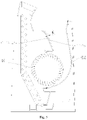
- the air duct component 20 comprises a first volute member 21 and a second volute member 22 which are arranged oppositely, and the first volute member 21 and the second volute member 22 are oppositely disposed in a cross section perpendicular to an axis of the cross-flow impeller 10 (for example, in the cross section shown in Fig. 1 ), so as to form a cross-flow air duct 23 between the first volute member 21 and the second volute member 22, and referring to Fig. 2 , in an axial direction of the cross-flow impeller 10, the cross-flow air duct 23 comprises a middle air duct section 231 and two end air duct sections 232 located at two ends of the middle air duct section 231 respectively.
- the cross-flow air duct 23 comprises the middle air duct section 231 (the region between line M1 and line M2 shown in Fig. 2 ), the end air duct section 232 located on the left side of the middle air duct section 231 (the region on the left side of line M1 shown in Fig. 2 ), and the end air duct section 232 located on the right side of the middle air duct section 231 (the region on the right side of line M2 shown in Fig. 2 ).
- an inner end of the first volute member 21 comprises a volute tongue 211, and it should be noted that “inner” described herein refers to the side close to an air inlet 23b of the cross-flow air duct 23, and “outer” refers to the side close to an air outlet 23c of the cross-flow impeller 10.
- a vertical line L is drawn through the volute tongue 211 towards the second volute member 22, and it should be noted that the above-mentioned vertical line L is the shortest one of all vertical lines drawn from all points on the volute tongue 211 to the second volute member 22, i.e., a vertical line with a minimum distance from the volute tongue 211 to the second volute member 22.
- the part of the cross-flow air duct 23 located at the vertical line L may be referred to as a throat portion 23a of the cross-flow air duct 23, and when the cross-flow impeller 10 works, airflow enters the cross-flow air duct 23 from the air inlet 23b thereof, and flows through the throat portion 23a thereof to the air outlet 23c thereof.
- the part of the middle air duct section 231 located downstream of the vertical line L serves as a middle air outlet duct 231a
- the part of the end air duct section 232 located downstream of the vertical line L serves as an end air outlet duct 232a; that is, the airflow enters the cross-flow air duct 23 from the air inlet 23b, a part of the airflow enters the middle air duct section 231 of the cross-flow air duct 23, the rest of the airflow enters the end air duct section 232 of the cross-flow air duct 23, the airflow entering the middle air duct section 231 flows through the throat portion 23a to the middle air outlet duct 231a, and the airflow entering the end air duct section 232 flows through the throat portion 23a to the end air outlet duct 232a.
- the middle air outlet duct 231a has a cross-sectional area S1
- the end air outlet duct 232a has a cross-sectional area S2, and S2 ⁇ S1.
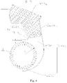
- the middle air duct section 231 is formed between the first volute member 21, which is entirely represented by a solid line section, and the second volute member 22; correspondingly, in Fig. 3 , the shaded region in Fig. 3 is the cross-sectional area of the middle air outlet duct 231a.
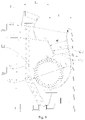
- the end air duct section 232 is formed between the first volute member 21 having a dotted line section and the second volute member 22; correspondingly in Fig.
- the shaded region in Fig. 4 is the cross-sectional area of the end air outlet duct 232a. Since the first volute member 21 having the dotted line section in Fig. 1 is located on the side of the first volute member 21 entirely represented by the solid line section close to the second volute member 22, it is apparent that S2 ⁇ S 1.
- the cross-sectional area S2 of the end air outlet duct 232a is set to be smaller than the cross-sectional area S1 of the middle air outlet duct 231a, such that a larger air outlet area exists in the middle in a length direction of the cross-flow air duct 23 (i.e., an axial direction of the cross-flow impeller 10), and may be matched with a higher air outlet speed, and smaller air outlet areas exist at two end portions and may be matched with lower air outlet speeds, such that airflow loads which are substantially the same exist in a whole length range of the cross-flow air duct 23, and the airflow is uniform, thus effectively improving air-supply abnormal noise generated at the two end portions of the cross-flow air duct 23.
- cross-flow impellers are adopted to be matched with cross-flow air ducts; however, in a working process of the cross-flow impeller, air unevenly flows in the whole length range of the cross-flow air duct, resulting in airflow abnormal noise in the cross-flow air duct.
- the cross-flow impeller has a smaller length than the cross-flow air duct, and under influences of two side wall surfaces of the cross-flow air duct, the higher air speed exists in the middle in the length direction of the cross-flow air duct (i.e., the axial direction of the cross-flow impeller), and the lower air speed exists near the two side wall surfaces.
- the cross-flow air duct 23 has different air outlet sections in the whole length range and has a variable section design, such that the middle air outlet duct 231a with the larger cross-sectional area may be adapted to the higher air outlet speed, and the end air outlet duct 232a with the smaller cross-sectional area may be adapted to the lower air outlet speed; or, the cross-flow air duct 23 is set to have a variable section structure, such that the middle air outlet duct 231a with the larger cross-sectional area is matched in the middle with the higher air speed, and the end air outlet ducts 232a with the smaller cross-sectional areas are matched on the two sides with the lower air speeds, so as to ensure that the airflow loads are substantially the same in the whole length range of the cross-flow air duct 23,
- the first volute member 21 and/or the second volute member 22 are/is provided to have a variable section design along the axial direction of the cross-flow impeller 10; that is, the first volute member 21 and/or the second volute member 22 may be provided to have different sectional shapes in the middle and two ends in the axial direction of the cross-flow impeller 10, thereby adapting to load changes at different positions, and effectively eliminating the air-supply abnormal noise on the two sides of the cross-flow air duct 23.
- first volute member 21 and/or the second volute member 22 may have the variable section design along the axial direction of the cross-flow impeller 10, influences of end walls of the two sides of the cross-flow air duct 23 on an air volume may be adapted, such that the air more uniformly flows in the whole length direction (i.e., the axial direction of the cross-flow impeller 10) of the whole cross-flow air duct 23, thus adapting to the characteristics of the cross-flow air duct 23 that the middle air speed is higher and the air speeds on the two sides are lower, and improving the noise generated by the nonuniform airflow on the two sides of the cross-flow air duct 23.
- transition may be performed by a smooth curved surface or a stepped surface at section varying positions of the first volute member 21 and the second volute member 22, which will not be limited herein.
- a length of the cross-flow air duct 23 is W1
- a length of the end air duct section 232 is W2, and 5 mm ⁇ W2 ⁇ 0.3W1. That is, the length W2 of the end air duct section 232 is less than or equal to 0.3 times the axial length of the cross-flow air duct 23, and greater than or equal to 5 mm, thus preventing the outlet air of the middle air duct section 231 from being greatly influenced by the length of the end air duct section 232, and avoiding the problem that an improvement effect on the abnormal noise on the two sides is not obvious due to the small length of the end air duct section 232.
- the present application is not limited thereto, and the length W2 of the end air duct section 232 may also be adjusted according to actual situations, which is not repeated herein. Furthermore, it should be noted that the length of the end air duct section 232 is only required to meet the value, but the lengths of the two end air duct sections 232 are not required to be consistent, and may be equal or unequal.
- the part of the volute tongue 211 corresponding to the middle air duct section 231 serves as a middle volute tongue section 211a
- the part of the volute tongue 211 corresponding to the end air duct section 232 serves as an end volute tongue section 211b
- the middle volute tongue section 211a and the cross-flow impeller 10 have a minimum gap T1
- the end volute tongue section 211b and the cross-flow impeller 10 have a minimum gap T2
- T2>T1 the inner end of the first volute member 21 is configured as the volute tongue 211
- the air inlet 23b of the cross-flow air duct 23 is formed between the volute tongue 211 and the inner end of the second volute member 22.
- the volute tongue 211 is provided to have a variable section structure with a small gap between a middle part and the cross-flow impeller 10 and large gaps between two end parts and the cross-flow impeller 10, thus effectively adapting to the characteristics of small air volumes on the two sides and a large air volume in the middle of the cross-flow air duct 23, improving air volume uniformity of the cross-flow air duct 23 in the whole length direction to a certain extent (that is, the air volume is small due to airflow loss on the two sides of the cross-flow air duct 23, and air inlet resistance on the two sides may be reduced by increasing the air inlet gaps on the two sides, thereby increasing the air inlet volumes on the two sides), and reducing the noise of the air duct component 20 to a certain extent.
- the first volute member 21 in the axial direction of the cross-flow impeller 10, is of a variable section design, and minimum distances from the volute tongue 211 to the cross-flow impeller 10, minimum distance positions, as well as angles and shapes of the volute tongue 211 may be different at the two ends and in the middle.
- a diameter of the cross-flow impeller 10 is D, 0.04D ⁇ T2 ⁇ 0.06D, and 0.04D ⁇ T1 ⁇ 0.06D.
- the gap may be 0.04D, 0.045D, 0.05D, 0.055D, 0.06D, or the like, thereby guaranteeing a better performance of the cross-flow air duct 23.
- the first volute member 21 comprises a first linear section 212
- the volute tongue 211 is connected to an inner end of the first linear section 212
- the part of the first linear section 212 corresponding to the middle air duct section 231 serves as a first middle linear section 212a
- the part of the first linear section 212 corresponding to the end air duct section 232 serves as a first end linear section 212b.
- an outer end of the first end linear section 212b is located on the side of an outer end of the first middle linear section 212a close to the second volute member 22.
- the cross-sectional area S2 of the end air outlet duct 232a may be simply and effectively guaranteed to be set to be smaller than the cross-sectional area S1 of the middle air outlet duct 231a, such that the middle air outlet duct 231a with the larger cross-sectional area is matched in the middle with the higher air speed, and the end air outlet ducts 232a with the smaller cross-sectional areas are matched on the two sides with the lower air speeds, so as to ensure that the airflow loads are substantially the same in the whole length range of the cross-flow air duct 23, and the airflow is uniform, thereby reducing the discontinuous airflow sounds generated on the two sides of the cross-flow air duct 23 and improving the airflow abnormal noise.
- an inner end of the first end linear section 212b coincides with an inner end of the first middle linear section 212a
- the first end linear section 212b and the first middle linear section 212a have an included angle ⁇ 1, and 3° ⁇ 1 ⁇ 7°, for example, ⁇ 1 may be 3°, 4°, 5°, 6°, 7°, or the like. That is, when the first middle linear section 212a is rotated by ⁇ 1 towards the second volute member 22 with the inner end as a center of rotation, the first end linear section 212b may be obtained.
- the dotted line part of the first linear section 212 represents the first end linear section 212b
- the solid line part of the first linear section 212 represents the first middle linear section 212a.
- a difference angle of 3° to 7° is formed between the first end linear section 212b and the first middle linear section 212a, such that the cross-sectional area S2 of the end air outlet duct 232a may be simply and effectively guaranteed to be set to be smaller than the cross-sectional area S1 of the middle air outlet duct 231a, the middle air outlet duct 231a with the larger cross-sectional area is matched in the middle with the higher air speed, and the end air outlet ducts 232a with the smaller cross-sectional areas are matched on the two sides with the lower air speeds, so as to ensure that the airflow loads are substantially the same in the whole length range of the cross-flow air duct 23, and the airflow is uniform, thereby reducing the discontinuous airflow sounds generated on the two sides of the cross-flow air duct 23, improving the airflow abnormal noise, and avoiding the problem that normal air discharge on the two sides is influenced by the overlarge difference angle between the first end linear section 212b and the first middle linear section 212a.
- the part of an inner end portion of the second volute member 22 corresponding to the middle air duct section 231 serves as a middle inner end section 22a1
- the part of the inner end portion of the second volute member 22 corresponding to the end air duct section 232 serves as an end-portion inner end section 22b1
- the middle inner end section 22a1 and the cross-flow impeller 10 have a minimum gap T3
- the end-portion inner end section 22b1 and the cross-flow impeller 10 have a minimum gap T4, and T4>T3.
- the dotted line represents the middle inner end section 22a1
- the solid line represents the end-portion inner end section 22b1.
- the inner end of the second volute member 22 is provided to have a variable section structure with a small gap between a middle part and the cross-flow impeller 10 and large gaps between two end parts and the cross-flow impeller 10, thus effectively adapting to the characteristics of the small air volumes on the two sides and the large air volume in the middle of the cross-flow air duct 23, improving the air volume uniformity of the cross-flow air duct 23 in the whole length direction to a certain extent (that is, the air volume is small due to the airflow loss on the two sides of the cross-flow air duct 23, and the air inlet resistance on the two sides may be reduced by increasing the air inlet gaps on the two sides, thereby increasing the air inlet volumes on the two sides), and reducing the noise of the air duct component 20 to a certain extent.
- the second volute member 22 in the axial direction of the cross-flow impeller 10, is of a variable section design, and minimum distances from the inner end of the second volute member 22 to the cross-flow impeller 10, minimum distance positions, as well as angles and shapes of the second volute member 22 may be different at the two ends and in the middle.
- a diameter of the cross-flow impeller 10 is D, 0.04D ⁇ T3 ⁇ 0.06D, and 0.04D ⁇ T4 ⁇ 0.06D.
- the gap may be 0.04D, 0.045D, 0.05D, 0.055D, 0.06D, or the like, thereby guaranteeing the better performance of the cross-flow air duct 23.
- the second volute member 22 comprises a second linear section 221, the part of the second linear section 221 corresponding to the middle air duct section 231 serves as a second middle linear section 221a, the part of the second linear section 221 corresponding to the end air duct section 232 serves as a second end linear section 221b, and an outer end of the second end linear section 221b is located on the side of an outer end of the second middle linear section 221a close to the first volute member 21.
- the cross-sectional area S2 of the end air outlet duct 232a may be simply and effectively guaranteed to be set to be smaller than the cross-sectional area S1 of the middle air outlet duct 231a, such that the middle air outlet duct 231a with the larger cross-sectional area is matched in the middle with the higher air speed, and the end air outlet ducts 232a with the smaller cross-sectional areas are matched on the two sides with the lower air speeds, so as to ensure that the airflow loads are substantially the same in the whole length range of the cross-flow air duct 23, and the airflow is uniform, thereby reducing the discontinuous airflow sounds generated on the two sides of the cross-flow air duct 23 and improving the airflow abnormal noise.
- an inner end of the second end linear section 221b coincides with an inner end of the second middle linear section 221a
- the second end linear section 221b and the second middle linear section 221a have an included angle ⁇ 2, and 3° ⁇ 2 ⁇ 7°, for example, ⁇ 2 may be 3°, 4°, 5°, 6°, 7°, or the like. That is, when the second middle linear section 221a is rotated by ⁇ 2 towards the first volute member 21 with the inner end as a center of rotation, the second end linear section 221b may be obtained.
- the solid line represents the second end linear section 221b
- the dotted line represents the second middle linear section 221a.
- a difference angle of 3° to 7° is formed between the second end linear section 221b and the second middle linear section 221a, such that the cross-sectional area S2 of the end air outlet duct 232a may be simply and effectively guaranteed to be set to be smaller than the cross-sectional area S1 of the middle air outlet duct 231a, the middle air outlet duct 231a with the larger cross-sectional area is matched in the middle with the higher air speed, and the end air outlet ducts 232a with the smaller cross-sectional areas are matched on the two sides with the lower air speeds, so as to ensure that the airflow loads are substantially the same in the whole length range of the cross-flow air duct 23, and the airflow is uniform, thereby reducing the discontinuous airflow sounds generated on the two sides of the cross-flow air duct 23, improving the airflow abnormal noise, and avoiding the problem that the normal air discharge on the two sides is influenced by the overlarge difference angle between the second end linear section 221b and the second middle linear section 221a.
- the part of the second volute member 22 corresponding to the middle air duct section 231 serves as a second middle volute section 22a
- the part of the second volute member 22 corresponding to the end air duct section 232 serves as a second end volute section 22b
- the second end volute section 22b is deflected by an angle ⁇ 3 relative to the second middle volute section 22a about a central axis of the cross-flow impeller 10 towards the first volute member 21, and 3° ⁇ 3 ⁇ 7°, for example, ⁇ 3 may be 3°, 4°, 5°, 6°, 7°, or the like.
- the second middle volute section 22a when the second middle volute section 22a is rotated by ⁇ 3 towards the first volute member 21 with the axis of the cross-flow impeller 10 as a center of rotation, the second end volute section 22b may be obtained. It may be understood that in Fig. 8 , the solid line represents the second end volute section 221b, and the dotted line represents the second middle volute section 22a.
- a difference angle of 3° to 7° around the axis of the cross-flow impeller 10 is formed between the second end volute section 22b and the second middle volute section 22a, such that the cross-sectional area S2 of the end air outlet duct 232a may be simply and effectively guaranteed to be set to be smaller than the cross-sectional area S1 of the middle air outlet duct 231a, the middle air outlet duct 231a with the larger cross-sectional area is matched in the middle with the higher air speed, and the end air outlet ducts 232a with the smaller cross-sectional areas are matched on the two sides with the lower air speeds, so as to ensure that the airflow loads are substantially the same in the whole length range of the cross-flow air duct 23, and the airflow is uniform, thereby reducing the discontinuous airflow sounds generated on the two sides of the cross-flow air duct 23, improving the airflow abnormal noise, and avoiding the problem that the normal air discharge on the two sides is influenced by the overlarge difference angle between the second end volute section 22
- the part of the first volute member 21 corresponding to the middle air duct section 231 serves as a first middle volute section 21a
- the part of the second volute member 22 corresponding to the middle air duct section 231 serves as a second middle volute section 22a
- the part of the first volute member 21 corresponding to the end air duct section 232 serves as a first end volute section 21b
- the part of the second volute member 22 corresponding to the end air duct section 232 serves as a second end volute section 22b
- the first middle volute section 21a and the second middle volute section 22a have an included angle ⁇ 4
- the first end volute section 21b and the second end volute section 22b have an included angle ⁇ 5, and ⁇ 5 ⁇ 4.
- the first middle volute section 21a comprises a first middle linear section 212a
- the first end volute section 21b comprises a first end linear section 212b
- the second middle volute section 22a comprises a second middle linear section 221a
- the second end volute section 22b comprises a second end linear section 221b
- the included angle ⁇ 4 between the first middle volute section 21a and the second middle volute section 22a is an included angle between the first middle linear section 212a and the second middle linear section 221a
- the included angle ⁇ 5 between the first end volute section 21b and the second end volute section 22b is an included angle between the first end linear section 212b and the second end linear section 221b.
- the cross-sectional area S2 of the end air outlet duct 232a may be simply and effectively guaranteed to be set to be smaller than the cross-sectional area S1 of the middle air outlet duct 231a, such that the middle air outlet duct 231a with the larger cross-sectional area is matched in the middle with the higher air speed, and the end air outlet ducts 232a with the smaller cross-sectional areas are matched on the two sides with the lower air speeds, so as to ensure that the airflow loads are substantially the same in the whole length range of the cross-flow air duct 23, and the airflow is uniform, thereby reducing the discontinuous airflow sounds generated on the two sides of the cross-flow air duct 23 and improving the airflow abnormal noise.
- 3° ⁇ 5- ⁇ 4 ⁇ 7° that is, included angles between the first volute member 21 and the second volute member 22 have a difference value of 3° to 7° at the two ends and in the middle, for example, the difference value may be 3°, 4°, 5°, 6°, 7°, thereby reducing discontinuous airflow sounds generated on the two sides of the cross-flow air duct 23, improving the airflow abnormal noise, and avoiding the problem that the normal air discharge on the two sides is influenced by the overlarge difference value.
- both ⁇ 4 and ⁇ 5 may be 3°, 6°, 9°, 12°, 15°, 20°, or the like.
- the included angles between the first volute member 21 and the second volute member 22 are different at the two ends and in the middle, but between 3° and 20°, thereby guaranteeing the better performance of the cross-flow air duct 23.
- the above-mentioned vertical line L has a length H; that is, the size from the first volute member 21 to the second volute member 22 at the throat portion 23a of the cross-flow air duct 23 is H, or the minimum size from the first volute member 21 to the second volute member 22 is H, a diameter of the cross-flow impeller 10 is D, and 0.45D ⁇ H ⁇ 0.65D, thus avoiding a small air volume caused by too small H, and the abnormal noise caused by too large H.
- the air conditioning apparatus 100 may comprise a cross-flow impeller 10 and the air duct component 20 for a cross-flow impeller 10 according to any embodiment of the first aspect of the present application, wherein the cross-flow impeller 10 is provided at the cross-flow air duct 23.
- the cross-flow impeller 10 may be provided at the air inlet 23b of the cross-flow air duct 23.
- the cross-sectional area S2 of the end air outlet duct 232a is set to be smaller than the cross-sectional area S1 of the middle air outlet duct 231a, such that the larger air outlet area exists in the middle in the length direction of the cross-flow air duct 23 (i.e., the axial direction of the cross-flow impeller 10), and may be matched with the higher air outlet speed, and the smaller air outlet areas exist at the two end portions and may be matched with the lower air outlet speeds, such that the airflow loads which are substantially the same exist in the whole length range of the cross-flow air duct 23, and the airflow is uniform, thus effectively improving the air-supply abnormal noise generated at the two end portions of the cross-flow air duct 23.
- the air conditioning apparatus 100 may be configured as an air conditioner or an air sterilizer, or the like, and when configured as an air conditioner, the air conditioning apparatus 100 may further include a heat exchanger 30 which may be provided upstream and/or downstream of the air duct component 20, such that the air conditioner may adjust an air temperature.
- the air conditioning apparatus 100 may further include a sterilizing device which may be provided upstream and/or downstream of the air duct component 20, such that the air sterilizer may sterilize and disinfect air.
- the air conditioning apparatus 100 when configured as an air conditioner, there is no limitation in the specific type of the air conditioner, and the air conditioner may be configured as an air conditioner indoor unit (including a cabinet air conditioner indoor unit or a wall mount air conditioner indoor unit, or the like) in a split air conditioner, or a mobile air conditioner or a window air conditioner, or the like, in an all-in-one air conditioner.
- the specific type of the air conditioning apparatus 100 is determined, other configurations and operations of the air conditioning apparatus 100 according to the embodiments of the present application are known to those skilled in the art and will not be described in detail herein.
- the air conditioning apparatus 100 is configured as a mobile air conditioner and comprises the heat exchanger 30, the heat exchanger 30 is provided on a rear side of the cross-flow impeller 10, the cross-flow impeller 10 is provided at an entrance of the cross-flow air duct 23, and the second volute member 22 is located on a front side of the first volute member 21;
- the heat exchanger 30 comprises a first heat exchange member 31 extending vertically, the axis of the cross-flow impeller 10 and a rear surface of the first heat exchange member 31 have a horizontal distance L1, and a rear surface of the second volute member 22 and the axis of the cross-flow impeller 10 have a maximum horizontal distance L2; that is, the horizontal distance from an outer edge of the heat exchanger 30 to a center of the cross-flow impeller 10 is L1, the maximum horizontal distance from the inner surface of the second volute member 22 to the center of the cross-flow impeller 10 is L2, and the diameter of the cross-flow
- 0.7D ⁇ L1 ⁇ D thus avoiding the abnormal noise due to a high speed of the air passing through the heat exchanger 30 caused by too small L1, and the large size and cost caused by too large L1.
- 0.65D ⁇ L2 ⁇ D thus avoiding the abnormal noise caused by too small L2, and the large complete-machine size and cost caused by too large L2.
- a mobile air conditioner in the related art usually has a very small and compact space size, such that a distance from a heat exchanger to a cross-flow impeller is small, airflow passing through a heat exchanger has a high speed, whining noise is generated, and performance advantages of a cross-flow air duct are unable to be developed to the maximum extent.
- the heat exchanger 30 may further include, in addition to the first heat exchange member 31 which is provided vertically, a second heat exchange member 32 which is located below the first heat exchange member 31 and is provided obliquely, thus enhancing a heat exchanging effect, and certainly, the heat exchanger 30 may also be in other forms, which are not repeated herein.
- first and second are used herein for purposes of description and are not intended to indicate or imply relative importance or significance or to imply the number of indicated technical features.
- the feature associated with “first” and “second” may comprise one or more of this feature explicitly or implicitly.
- "a plurality of' means two or more unless otherwise specified.
- a structure in which a first feature is "on" or “below” a second feature may comprise an embodiment in which the first feature is in direct contact with the second feature, and may also include an embodiment in which the first feature and the second feature are contacted via an additional feature formed therebetween.
- a first feature "on,” “above,” or “on top of' a second feature may comprise an embodiment in which the first feature is right or obliquely “on,” “above,” or “on top of' the second feature, or just means that the first feature is at a height higher than that of the second feature; while a first feature "below,” “under,” or “on bottom of' a second feature may comprise an embodiment in which the first feature is right or obliquely “below,” “under,” or “on bottom of' the second feature, or just means that the first feature is at a height lower than that of the second feature.
Landscapes
- Engineering & Computer Science (AREA)
- Mechanical Engineering (AREA)
- General Engineering & Computer Science (AREA)
- Structures Of Non-Positive Displacement Pumps (AREA)
Applications Claiming Priority (3)
| Application Number | Priority Date | Filing Date | Title |
|---|---|---|---|
| CN202022273245.5U CN213478701U (zh) | 2020-10-13 | 2020-10-13 | 用于贯流风轮的风道部件和具有其的空气调节设备 |
| CN202011088504.5A CN112128126B (zh) | 2020-10-13 | 2020-10-13 | 用于贯流风轮的风道部件和具有其的空气调节设备 |
| PCT/CN2020/129052 WO2022077688A1 (fr) | 2020-10-13 | 2020-11-16 | Élément de conduit d'air pour roue à écoulement transversal, et dispositif de climatisation le comprenant |
Publications (4)
| Publication Number | Publication Date |
|---|---|
| EP4012189A1 true EP4012189A1 (fr) | 2022-06-15 |
| EP4012189A4 EP4012189A4 (fr) | 2022-10-12 |
| EP4012189B1 EP4012189B1 (fr) | 2024-05-29 |
| EP4012189C0 EP4012189C0 (fr) | 2024-05-29 |
Family
ID=80735661
Family Applications (1)
| Application Number | Title | Priority Date | Filing Date |
|---|---|---|---|
| EP20914785.9A Active EP4012189B1 (fr) | 2020-10-13 | 2020-11-16 | Élément de conduit d'air pour roue à écoulement transversal, et dispositif de climatisation le comprenant |
Country Status (4)
| Country | Link |
|---|---|
| US (1) | US11939988B2 (fr) |
| EP (1) | EP4012189B1 (fr) |
| CA (1) | CA3126005C (fr) |
| WO (1) | WO2022077688A1 (fr) |
Families Citing this family (3)
| Publication number | Priority date | Publication date | Assignee | Title |
|---|---|---|---|---|
| CN116992601B (zh) * | 2023-09-27 | 2023-12-26 | 广东顺威精密塑料股份有限公司 | 一种蜗壳流道的设计方法 |
| CN118881586B (zh) * | 2024-08-12 | 2026-06-05 | 宁波方太厨具有限公司 | 风扇、热风单元及烘烤烹饪设备 |
| CN118960092B (zh) * | 2024-08-30 | 2025-12-19 | 青岛海尔空调器有限总公司 | 柜式空调器 |
Family Cites Families (13)
| Publication number | Priority date | Publication date | Assignee | Title |
|---|---|---|---|---|
| JP3067875B2 (ja) * | 1992-01-22 | 2000-07-24 | 松下電器産業株式会社 | 空気調和機 |
| JPH08303393A (ja) * | 1995-05-01 | 1996-11-19 | Daikin Ind Ltd | クロスフローファン |
| KR100438595B1 (ko) * | 1996-08-30 | 2004-08-31 | 엘지전자 주식회사 | 분리형에어콘실내기의크로스플로팬구조 |
| CN2676085Y (zh) * | 2003-12-26 | 2005-02-02 | 东风汽车有限公司 | 一种送风管道 |
| JP2006336514A (ja) * | 2005-05-31 | 2006-12-14 | Sharp Corp | 空気調和機 |
| KR101485609B1 (ko) * | 2008-11-26 | 2015-01-22 | 엘지전자 주식회사 | 공기 조화기의 실내기 |
| CN103062874A (zh) | 2011-10-24 | 2013-04-24 | 海信科龙电器股份有限公司 | 一种贯流风道系统 |
| CN104729039B (zh) * | 2013-12-23 | 2017-12-19 | 珠海格力电器股份有限公司 | 贯流风道系统及具有其的空调器 |
| CN105605685A (zh) | 2016-03-15 | 2016-05-25 | 李丹 | 立式空调室内机 |
| CN109790842B (zh) * | 2016-09-30 | 2021-03-23 | 大金工业株式会社 | 横流式风机及包括该横流式风机的空调装置的室内机组 |
| CN208186765U (zh) * | 2018-03-20 | 2018-12-04 | 广东美的制冷设备有限公司 | 空调器 |
| CN108592180A (zh) * | 2018-03-20 | 2018-09-28 | 广东美的制冷设备有限公司 | 空调器室内机及空调器 |
| CN209689044U (zh) | 2019-03-20 | 2019-11-26 | 广东美的制冷设备有限公司 | 风道部件和具有其的空气处理设备 |
-
2020
- 2020-11-16 US US17/424,420 patent/US11939988B2/en active Active
- 2020-11-16 EP EP20914785.9A patent/EP4012189B1/fr active Active
- 2020-11-16 CA CA3126005A patent/CA3126005C/fr active Active
- 2020-11-16 WO PCT/CN2020/129052 patent/WO2022077688A1/fr not_active Ceased
Also Published As
| Publication number | Publication date |
|---|---|
| US11939988B2 (en) | 2024-03-26 |
| US20220372991A1 (en) | 2022-11-24 |
| EP4012189B1 (fr) | 2024-05-29 |
| EP4012189C0 (fr) | 2024-05-29 |
| CA3126005A1 (fr) | 2022-04-13 |
| EP4012189A4 (fr) | 2022-10-12 |
| CA3126005C (fr) | 2023-09-26 |
| WO2022077688A1 (fr) | 2022-04-21 |
Similar Documents
| Publication | Publication Date | Title |
|---|---|---|
| EP4012189B1 (fr) | Élément de conduit d'air pour roue à écoulement transversal, et dispositif de climatisation le comprenant | |
| CN106247460B (zh) | 壁挂式空调器及其控制方法 | |
| CN205481342U (zh) | 空调室内机及空调系统 | |
| CN206094309U (zh) | 空调器室内机以及空调器 | |
| CN105674399A (zh) | 一种混合出风空调室内机 | |
| CN106322535A (zh) | 空调器室内机以及空调器 | |
| JP3695740B2 (ja) | 空気調和機の室内ユニット | |
| WO2018062540A1 (fr) | Soufflante à flux transversal et unité intérieure d'un dispositif de conditionnement d'air équipé de cette dernière | |
| CN106287989B (zh) | 贯流空调器及其控制方法 | |
| CN105546648A (zh) | 空调室内机及空调系统 | |
| CN112128126B (zh) | 用于贯流风轮的风道部件和具有其的空气调节设备 | |
| WO2020048203A1 (fr) | Ensemble canal d'air et climatiseur | |
| CN212691952U (zh) | 蜗舌、风机组件和空调室内机 | |
| US12163671B2 (en) | Air conditioner | |
| CN208382343U (zh) | 空调室内机和空调器 | |
| JP2023515516A (ja) | 空気調和機 | |
| CN213478701U (zh) | 用于贯流风轮的风道部件和具有其的空气调节设备 | |
| CN220524220U (zh) | 空调器 | |
| WO2017049447A1 (fr) | Unité intérieure à sortie d'air mélangé de climatiseur | |
| WO2017049522A1 (fr) | Unité intérieure de climatiseur | |
| JP2005037001A (ja) | 空気調和機の室内ユニット | |
| CN111981566B (zh) | 风机及空调室内机 | |
| CN213478685U (zh) | 用于贯流风轮的风道部件和具有其的空气调节设备 | |
| CN208332463U (zh) | 空调室内机和空调器 | |
| WO2017049542A1 (fr) | Unité intérieure de climatiseur |
Legal Events
| Date | Code | Title | Description |
|---|---|---|---|
| STAA | Information on the status of an ep patent application or granted ep patent |
Free format text: STATUS: UNKNOWN |
|
| STAA | Information on the status of an ep patent application or granted ep patent |
Free format text: STATUS: THE INTERNATIONAL PUBLICATION HAS BEEN MADE |
|
| PUAI | Public reference made under article 153(3) epc to a published international application that has entered the european phase |
Free format text: ORIGINAL CODE: 0009012 |
|
| STAA | Information on the status of an ep patent application or granted ep patent |
Free format text: STATUS: REQUEST FOR EXAMINATION WAS MADE |
|
| 17P | Request for examination filed |
Effective date: 20210730 |
|
| AK | Designated contracting states |
Kind code of ref document: A1 Designated state(s): AL AT BE BG CH CY CZ DE DK EE ES FI FR GB GR HR HU IE IS IT LI LT LU LV MC MK MT NL NO PL PT RO RS SE SI SK SM TR |
|
| A4 | Supplementary search report drawn up and despatched |
Effective date: 20220914 |
|
| RIC1 | Information provided on ipc code assigned before grant |
Ipc: F04D 17/04 20060101ALI20220908BHEP Ipc: F04D 29/44 20060101ALI20220908BHEP Ipc: F04D 29/42 20060101ALI20220908BHEP Ipc: F04D 29/30 20060101ALI20220908BHEP Ipc: F04D 25/08 20060101AFI20220908BHEP |
|
| DAV | Request for validation of the european patent (deleted) | ||
| DAX | Request for extension of the european patent (deleted) | ||
| GRAP | Despatch of communication of intention to grant a patent |
Free format text: ORIGINAL CODE: EPIDOSNIGR1 |
|
| STAA | Information on the status of an ep patent application or granted ep patent |
Free format text: STATUS: GRANT OF PATENT IS INTENDED |
|
| RIC1 | Information provided on ipc code assigned before grant |
Ipc: F04D 17/04 20060101ALI20240226BHEP Ipc: F04D 29/44 20060101ALI20240226BHEP Ipc: F04D 29/42 20060101ALI20240226BHEP Ipc: F04D 29/30 20060101ALI20240226BHEP Ipc: F04D 25/08 20060101AFI20240226BHEP |
|
| INTG | Intention to grant announced |
Effective date: 20240314 |
|
| GRAS | Grant fee paid |
Free format text: ORIGINAL CODE: EPIDOSNIGR3 |
|
| GRAA | (expected) grant |
Free format text: ORIGINAL CODE: 0009210 |
|
| STAA | Information on the status of an ep patent application or granted ep patent |
Free format text: STATUS: THE PATENT HAS BEEN GRANTED |
|
| AK | Designated contracting states |
Kind code of ref document: B1 Designated state(s): AL AT BE BG CH CY CZ DE DK EE ES FI FR GB GR HR HU IE IS IT LI LT LU LV MC MK MT NL NO PL PT RO RS SE SI SK SM TR |
|
| REG | Reference to a national code |
Ref country code: CH Ref legal event code: EP |
|
| REG | Reference to a national code |
Ref country code: IE Ref legal event code: FG4D |
|
| REG | Reference to a national code |
Ref country code: DE Ref legal event code: R096 Ref document number: 602020031829 Country of ref document: DE |
|
| U01 | Request for unitary effect filed |
Effective date: 20240529 |
|
| U07 | Unitary effect registered |
Designated state(s): AT BE BG DE DK EE FI FR IT LT LU LV MT NL PT SE SI Effective date: 20240606 |
|
| PG25 | Lapsed in a contracting state [announced via postgrant information from national office to epo] |
Ref country code: IS Free format text: LAPSE BECAUSE OF FAILURE TO SUBMIT A TRANSLATION OF THE DESCRIPTION OR TO PAY THE FEE WITHIN THE PRESCRIBED TIME-LIMIT Effective date: 20240929 |
|
| PG25 | Lapsed in a contracting state [announced via postgrant information from national office to epo] |
Ref country code: HR Free format text: LAPSE BECAUSE OF FAILURE TO SUBMIT A TRANSLATION OF THE DESCRIPTION OR TO PAY THE FEE WITHIN THE PRESCRIBED TIME-LIMIT Effective date: 20240529 |
|
| PG25 | Lapsed in a contracting state [announced via postgrant information from national office to epo] |
Ref country code: GR Free format text: LAPSE BECAUSE OF FAILURE TO SUBMIT A TRANSLATION OF THE DESCRIPTION OR TO PAY THE FEE WITHIN THE PRESCRIBED TIME-LIMIT Effective date: 20240830 |
|
| PG25 | Lapsed in a contracting state [announced via postgrant information from national office to epo] |
Ref country code: ES Free format text: LAPSE BECAUSE OF FAILURE TO SUBMIT A TRANSLATION OF THE DESCRIPTION OR TO PAY THE FEE WITHIN THE PRESCRIBED TIME-LIMIT Effective date: 20240529 |
|
| PG25 | Lapsed in a contracting state [announced via postgrant information from national office to epo] |
Ref country code: PL Free format text: LAPSE BECAUSE OF FAILURE TO SUBMIT A TRANSLATION OF THE DESCRIPTION OR TO PAY THE FEE WITHIN THE PRESCRIBED TIME-LIMIT Effective date: 20240529 |
|
| PG25 | Lapsed in a contracting state [announced via postgrant information from national office to epo] |
Ref country code: PL Free format text: LAPSE BECAUSE OF FAILURE TO SUBMIT A TRANSLATION OF THE DESCRIPTION OR TO PAY THE FEE WITHIN THE PRESCRIBED TIME-LIMIT Effective date: 20240529 Ref country code: NO Free format text: LAPSE BECAUSE OF FAILURE TO SUBMIT A TRANSLATION OF THE DESCRIPTION OR TO PAY THE FEE WITHIN THE PRESCRIBED TIME-LIMIT Effective date: 20240829 Ref country code: IS Free format text: LAPSE BECAUSE OF FAILURE TO SUBMIT A TRANSLATION OF THE DESCRIPTION OR TO PAY THE FEE WITHIN THE PRESCRIBED TIME-LIMIT Effective date: 20240929 Ref country code: HR Free format text: LAPSE BECAUSE OF FAILURE TO SUBMIT A TRANSLATION OF THE DESCRIPTION OR TO PAY THE FEE WITHIN THE PRESCRIBED TIME-LIMIT Effective date: 20240529 Ref country code: GR Free format text: LAPSE BECAUSE OF FAILURE TO SUBMIT A TRANSLATION OF THE DESCRIPTION OR TO PAY THE FEE WITHIN THE PRESCRIBED TIME-LIMIT Effective date: 20240830 Ref country code: ES Free format text: LAPSE BECAUSE OF FAILURE TO SUBMIT A TRANSLATION OF THE DESCRIPTION OR TO PAY THE FEE WITHIN THE PRESCRIBED TIME-LIMIT Effective date: 20240529 Ref country code: RS Free format text: LAPSE BECAUSE OF FAILURE TO SUBMIT A TRANSLATION OF THE DESCRIPTION OR TO PAY THE FEE WITHIN THE PRESCRIBED TIME-LIMIT Effective date: 20240829 |
|
| U20 | Renewal fee for the european patent with unitary effect paid |
Year of fee payment: 5 Effective date: 20241122 |
|
| PG25 | Lapsed in a contracting state [announced via postgrant information from national office to epo] |
Ref country code: CZ Free format text: LAPSE BECAUSE OF FAILURE TO SUBMIT A TRANSLATION OF THE DESCRIPTION OR TO PAY THE FEE WITHIN THE PRESCRIBED TIME-LIMIT Effective date: 20240529 |
|
| PG25 | Lapsed in a contracting state [announced via postgrant information from national office to epo] |
Ref country code: SK Free format text: LAPSE BECAUSE OF FAILURE TO SUBMIT A TRANSLATION OF THE DESCRIPTION OR TO PAY THE FEE WITHIN THE PRESCRIBED TIME-LIMIT Effective date: 20240529 Ref country code: RO Free format text: LAPSE BECAUSE OF FAILURE TO SUBMIT A TRANSLATION OF THE DESCRIPTION OR TO PAY THE FEE WITHIN THE PRESCRIBED TIME-LIMIT Effective date: 20240529 |
|
| PG25 | Lapsed in a contracting state [announced via postgrant information from national office to epo] |
Ref country code: SM Free format text: LAPSE BECAUSE OF FAILURE TO SUBMIT A TRANSLATION OF THE DESCRIPTION OR TO PAY THE FEE WITHIN THE PRESCRIBED TIME-LIMIT Effective date: 20240529 |
|
| PG25 | Lapsed in a contracting state [announced via postgrant information from national office to epo] |
Ref country code: SM Free format text: LAPSE BECAUSE OF FAILURE TO SUBMIT A TRANSLATION OF THE DESCRIPTION OR TO PAY THE FEE WITHIN THE PRESCRIBED TIME-LIMIT Effective date: 20240529 Ref country code: SK Free format text: LAPSE BECAUSE OF FAILURE TO SUBMIT A TRANSLATION OF THE DESCRIPTION OR TO PAY THE FEE WITHIN THE PRESCRIBED TIME-LIMIT Effective date: 20240529 Ref country code: RO Free format text: LAPSE BECAUSE OF FAILURE TO SUBMIT A TRANSLATION OF THE DESCRIPTION OR TO PAY THE FEE WITHIN THE PRESCRIBED TIME-LIMIT Effective date: 20240529 Ref country code: CZ Free format text: LAPSE BECAUSE OF FAILURE TO SUBMIT A TRANSLATION OF THE DESCRIPTION OR TO PAY THE FEE WITHIN THE PRESCRIBED TIME-LIMIT Effective date: 20240529 |
|
| PLBE | No opposition filed within time limit |
Free format text: ORIGINAL CODE: 0009261 |
|
| STAA | Information on the status of an ep patent application or granted ep patent |
Free format text: STATUS: NO OPPOSITION FILED WITHIN TIME LIMIT |
|
| 26N | No opposition filed |
Effective date: 20250303 |
|
| REG | Reference to a national code |
Ref country code: CH Ref legal event code: PL |
|
| PG25 | Lapsed in a contracting state [announced via postgrant information from national office to epo] |
Ref country code: MC Free format text: LAPSE BECAUSE OF FAILURE TO SUBMIT A TRANSLATION OF THE DESCRIPTION OR TO PAY THE FEE WITHIN THE PRESCRIBED TIME-LIMIT Effective date: 20240529 |
|
| REG | Reference to a national code |
Ref country code: CH Ref legal event code: PL |
|
| GBPC | Gb: european patent ceased through non-payment of renewal fee |
Effective date: 20241116 |
|
| PG25 | Lapsed in a contracting state [announced via postgrant information from national office to epo] |
Ref country code: CH Free format text: LAPSE BECAUSE OF NON-PAYMENT OF DUE FEES Effective date: 20241130 |
|
| PG25 | Lapsed in a contracting state [announced via postgrant information from national office to epo] |
Ref country code: GB Free format text: LAPSE BECAUSE OF NON-PAYMENT OF DUE FEES Effective date: 20241116 |
|
| PG25 | Lapsed in a contracting state [announced via postgrant information from national office to epo] |
Ref country code: IE Free format text: LAPSE BECAUSE OF NON-PAYMENT OF DUE FEES Effective date: 20241116 |
|
| U20 | Renewal fee for the european patent with unitary effect paid |
Year of fee payment: 6 Effective date: 20251127 |
|
| PG25 | Lapsed in a contracting state [announced via postgrant information from national office to epo] |
Ref country code: HU Free format text: LAPSE BECAUSE OF FAILURE TO SUBMIT A TRANSLATION OF THE DESCRIPTION OR TO PAY THE FEE WITHIN THE PRESCRIBED TIME-LIMIT; INVALID AB INITIO Effective date: 20201116 |
|
| PG25 | Lapsed in a contracting state [announced via postgrant information from national office to epo] |
Ref country code: CY Free format text: LAPSE BECAUSE OF FAILURE TO SUBMIT A TRANSLATION OF THE DESCRIPTION OR TO PAY THE FEE WITHIN THE PRESCRIBED TIME-LIMIT; INVALID AB INITIO Effective date: 20201116 |
|
| PG25 | Lapsed in a contracting state [announced via postgrant information from national office to epo] |
Ref country code: TR Free format text: LAPSE BECAUSE OF FAILURE TO SUBMIT A TRANSLATION OF THE DESCRIPTION OR TO PAY THE FEE WITHIN THE PRESCRIBED TIME-LIMIT Effective date: 20240529 |