EP4012261A2 - Procédé pour brûler un combustible dans un poêle à bois, poêle à bois doté d'un dispositif de commande et régulateur d'air pour un poêle à bois - Google Patents
Procédé pour brûler un combustible dans un poêle à bois, poêle à bois doté d'un dispositif de commande et régulateur d'air pour un poêle à bois Download PDFInfo
- Publication number
- EP4012261A2 EP4012261A2 EP22150605.8A EP22150605A EP4012261A2 EP 4012261 A2 EP4012261 A2 EP 4012261A2 EP 22150605 A EP22150605 A EP 22150605A EP 4012261 A2 EP4012261 A2 EP 4012261A2
- Authority
- EP
- European Patent Office
- Prior art keywords
- state
- burn
- valve
- wood stove
- controller
- Prior art date
- Legal status (The legal status is an assumption and is not a legal conclusion. Google has not performed a legal analysis and makes no representation as to the accuracy of the status listed.)
- Granted
Links
Images







Classifications
-
- F—MECHANICAL ENGINEERING; LIGHTING; HEATING; WEAPONS; BLASTING
- F24—HEATING; RANGES; VENTILATING
- F24B—DOMESTIC STOVES OR RANGES FOR SOLID FUELS; IMPLEMENTS FOR USE IN CONNECTION WITH STOVES OR RANGES
- F24B13/00—Details solely applicable to stoves or ranges burning solid fuels
- F24B13/004—Doors specially adapted for stoves or ranges
-
- F—MECHANICAL ENGINEERING; LIGHTING; HEATING; WEAPONS; BLASTING
- F23—COMBUSTION APPARATUS; COMBUSTION PROCESSES
- F23N—REGULATING OR CONTROLLING COMBUSTION
- F23N3/00—Regulating air supply or draught
- F23N3/06—Regulating air supply or draught by conjoint operation of two or more valves or dampers
-
- F—MECHANICAL ENGINEERING; LIGHTING; HEATING; WEAPONS; BLASTING
- F23—COMBUSTION APPARATUS; COMBUSTION PROCESSES
- F23L—SUPPLYING AIR OR NON-COMBUSTIBLE LIQUIDS OR GASES TO COMBUSTION APPARATUS IN GENERAL ; VALVES OR DAMPERS SPECIALLY ADAPTED FOR CONTROLLING AIR SUPPLY OR DRAUGHT IN COMBUSTION APPARATUS; INDUCING DRAUGHT IN COMBUSTION APPARATUS; TOPS FOR CHIMNEYS OR VENTILATING SHAFTS; TERMINALS FOR FLUES
- F23L13/00—Construction of valves or dampers for controlling air supply or draught
- F23L13/06—Construction of valves or dampers for controlling air supply or draught slidable only
-
- F—MECHANICAL ENGINEERING; LIGHTING; HEATING; WEAPONS; BLASTING
- F23—COMBUSTION APPARATUS; COMBUSTION PROCESSES
- F23L—SUPPLYING AIR OR NON-COMBUSTIBLE LIQUIDS OR GASES TO COMBUSTION APPARATUS IN GENERAL ; VALVES OR DAMPERS SPECIALLY ADAPTED FOR CONTROLLING AIR SUPPLY OR DRAUGHT IN COMBUSTION APPARATUS; INDUCING DRAUGHT IN COMBUSTION APPARATUS; TOPS FOR CHIMNEYS OR VENTILATING SHAFTS; TERMINALS FOR FLUES
- F23L3/00—Arrangements of valves or dampers before the fire
-
- F—MECHANICAL ENGINEERING; LIGHTING; HEATING; WEAPONS; BLASTING
- F23—COMBUSTION APPARATUS; COMBUSTION PROCESSES
- F23L—SUPPLYING AIR OR NON-COMBUSTIBLE LIQUIDS OR GASES TO COMBUSTION APPARATUS IN GENERAL ; VALVES OR DAMPERS SPECIALLY ADAPTED FOR CONTROLLING AIR SUPPLY OR DRAUGHT IN COMBUSTION APPARATUS; INDUCING DRAUGHT IN COMBUSTION APPARATUS; TOPS FOR CHIMNEYS OR VENTILATING SHAFTS; TERMINALS FOR FLUES
- F23L9/00—Passages or apertures for delivering secondary air for completing combustion of fuel
- F23L9/04—Passages or apertures for delivering secondary air for completing combustion of fuel by discharging the air beyond the fire, i.e. nearer the smoke outlet
-
- F—MECHANICAL ENGINEERING; LIGHTING; HEATING; WEAPONS; BLASTING
- F23—COMBUSTION APPARATUS; COMBUSTION PROCESSES
- F23N—REGULATING OR CONTROLLING COMBUSTION
- F23N3/00—Regulating air supply or draught
- F23N3/002—Regulating air supply or draught using electronic means
-
- F—MECHANICAL ENGINEERING; LIGHTING; HEATING; WEAPONS; BLASTING
- F23—COMBUSTION APPARATUS; COMBUSTION PROCESSES
- F23N—REGULATING OR CONTROLLING COMBUSTION
- F23N5/00—Systems for controlling combustion
- F23N5/003—Systems for controlling combustion using detectors sensitive to combustion gas properties
- F23N5/006—Systems for controlling combustion using detectors sensitive to combustion gas properties the detector being sensitive to oxygen
-
- F—MECHANICAL ENGINEERING; LIGHTING; HEATING; WEAPONS; BLASTING
- F24—HEATING; RANGES; VENTILATING
- F24B—DOMESTIC STOVES OR RANGES FOR SOLID FUELS; IMPLEMENTS FOR USE IN CONNECTION WITH STOVES OR RANGES
- F24B1/00—Stoves or ranges
- F24B1/02—Closed stoves
- F24B1/028—Closed stoves with means for regulating combustion
-
- F—MECHANICAL ENGINEERING; LIGHTING; HEATING; WEAPONS; BLASTING
- F24—HEATING; RANGES; VENTILATING
- F24B—DOMESTIC STOVES OR RANGES FOR SOLID FUELS; IMPLEMENTS FOR USE IN CONNECTION WITH STOVES OR RANGES
- F24B5/00—Combustion-air or flue-gas circulation in or around stoves or ranges
- F24B5/02—Combustion-air or flue-gas circulation in or around stoves or ranges in or around stoves
- F24B5/021—Combustion-air or flue-gas circulation in or around stoves or ranges in or around stoves combustion-air circulation
- F24B5/026—Supply of primary and secondary air for combustion
-
- F—MECHANICAL ENGINEERING; LIGHTING; HEATING; WEAPONS; BLASTING
- F23—COMBUSTION APPARATUS; COMBUSTION PROCESSES
- F23N—REGULATING OR CONTROLLING COMBUSTION
- F23N2235/00—Valves, nozzles or pumps
- F23N2235/02—Air or combustion gas valves or dampers
- F23N2235/06—Air or combustion gas valves or dampers at the air intake
-
- F—MECHANICAL ENGINEERING; LIGHTING; HEATING; WEAPONS; BLASTING
- F23—COMBUSTION APPARATUS; COMBUSTION PROCESSES
- F23N—REGULATING OR CONTROLLING COMBUSTION
- F23N2237/00—Controlling
- F23N2237/10—High or low fire
-
- F—MECHANICAL ENGINEERING; LIGHTING; HEATING; WEAPONS; BLASTING
- F23—COMBUSTION APPARATUS; COMBUSTION PROCESSES
- F23N—REGULATING OR CONTROLLING COMBUSTION
- F23N2237/00—Controlling
- F23N2237/16—Controlling secondary air
Definitions
- the present invention provides wood stove and a method for burning a fuel in a wood stove having a door to a combustion chamber with a base, which combustion chamber is isolated from the air by an exhaust and an intake at which intake there is an air regulator having at least one valve, such as at least three valves, a primary valve connected via a primary air duct to regulate supply of primary combustion air to the combustion chamber through the base, a secondary valve connected via a secondary air duct to regulate supply of secondary combustion air to the combustion chamber between the base and the exhaust and preferably at the rear side, and a tertiary valve connected via a tertiary air duct to regulate supply of tertiary combustion air to the combustion chamber at the upper end and preferably at the front side, which valve(s) may be controlled by a burn controller configured to operate between burn states, such as the following states:
- This invention further relates to a wood stove burn controller, a wood stove air regulator and a kit of a wood stove burn controller and a wood stove air regulator.
- Wood burning stoves for heating houses and rooms have been know and are widespread. Although they are called wood burning stoves, wood is not the only type of fuel that is used to generate heat. Other fuels such as coal, coke, briquettes, pellets or other burnable materials can be burned in a wood stove or simply a stove.
- the fuel is placed in a combustion chamber, ignited and combustion air, i.e. air with some percentage of oxygen, is supplied to the chamber to allow for a burn or glow of the fuel.
- combustion air i.e. air with some percentage of oxygen
- a common type of wood burning stoves has a window, a door, or a door with a window on the front of the wood stove. At least there an opening for refuelling the combustion chamber with fuel.
- the burn is tried to be controlled by regulating the flow of combustion air to the combustion chamber either by changing the openness of the door.
- Some wood stoves have preset settings of valves for regulating the access of combustion air to the combustion chamber.
- An object of embodiments of the present invention is to provide means and methods that allow a wood stove to perform a more optimised burn.
- An object of embodiments of the present invention is to minimise the environmental impact from burning a fuel in the wood stove. This includes a reduction in the creation of particulate matter, sod, NO x , and other harmful by products from a non-optimal burn.
- An object of embodiments of the present invention is to allow for an optimal burn of different types of fuel and in particular fuel of the same type, but with different conditions such as wet, normal, dry, or more refined classifications of say wood.
- An object of embodiments of the present invention is to maximise the conversion of stored energy in the fuel to useful heat over a desired period of time.
- An object of embodiments of the present invention is to provide means and methods that allow for an easy usage of the wood stove. Hereby is understood a reduced need to monitor, change, or otherwise charge the combustion or burn process.
- An object of embodiments of the present invention is to provide a method and means for enabling an better and more efficient burn during real and varying conditions where the airflow in a chimney varies according to the specific installation, the weather conditions, where the wood changes according to availability, moist, type, where the user involvement, interest, and expertise varies or combinations thereof.
- the invention provides a wood stove burn controller comprising means for receiving inputs from exhaust measure means and/or a user interface and means for sending outputs to an air regulator, which outputs are generated by a burn control algorithm comprising a state machine with a plurality of burn states, such as five burn states:
- the invention further provides a wood stove air regulator comprising at least one valve, such as three valves and with a housing configured for fitting into a wood stove and configured for receiving control signals from a burn controller.
- the invention further provides a kit comprising the wood stove burn controller and the wood stove air regulator.
- the invention further provides a method for producing a wood stove comprising the steps:
- the invention further provides a wood stove comprising:
- the present invention provides a wood stove having a door to a combustion chamber with a base, which combustion chamber is isolated from the air by an exhaust and an intake at which intake there is an air regulator having at least three valves, a primary valve connected via a primary air duct to regulate supply of primary combustion air to the combustion chamber through the base, a secondary valve connected via a secondary air duct to regulate supply of tertiary combustion air to the combustion chamber between the base and the exhaust, and a tertiary valve connected via a tertiary air duct to supply tertiary combustion air to the combustion chamber at its upper end, wherein at least two of said three valves each are controlled via an intake control by a burn controller that is configured to manage at least five burn states of the wood stove.
- the present invention provides a method for burning a fuel in a wood stove having a door to a combustion chamber with a base, which combustion chamber is isolated from the air by an exhaust and an intake at which intake there is an air regulator having at least three valves, a primary valve connected via a primary air duct to regulate supply of primary combustion air to the combustion chamber through the base, a secondary valve connected via a secondary air duct to regulate supply of secondary combustion air to the combustion chamber between the base and the exhaust, and a tertiary valve connected via a tertiary air duct to supply tertiary combustion air to the combustion chamber at its upper end, wherein at least two of said three valves each are controlled by a burn controller configured to operate between the following states:
- valves preferably the tertiary valve may be replaced or constituted by a fixed, non-controllable element.
- valve may simply be constituted by a duct or other passage with no airflow control means provided therein.
- the secondary valve and secondary air duct are preferably provided at a rear side of the stove, i.e. that side opposite to the side comprising the door, which in the present context is denoted the front side.
- the tertiary valve and tertiary air duct are preferably provided at the front side of the stove.
- the tertiary air duct need not be provided with a controllable valve.
- the tertiary air duct may be kept at a fixed, i.e. constant position during at least the 0 th and 1 st - 3 rd states. In the fourth state, the fixed position may be maintained, or the valve in the tertiary air duct may be completely closed.
- the burn controller can be a micro-computer with a processor, an I/O-unit, and a storage.
- the burn controller has means for storing and executing a burn control algorithm.
- a cold start of a burn is understood to be when the wood stove, the combustion chamber and/or the fuel is provided as is and typically at ambient temperature. The temperature can vary from say -40° to say +70° Celsius. Although typical room temperatures will be from a few minus degrees to a room temperature in say the twenties degrees Celsius.
- the burn controller regulates the valves so that the primary valve is 100 % open, the secondary valve is 0% open (i.e. closed), and the tertiary valve is 0 % open.
- the tertiary valve may maintain a fixed position in embodiments, in which the tertiary valve is not controllable or maintained at a fixed position. In such embodiments, it may for example be approximately 50% open.
- thermometer When a certain temperature, say about 50°C is detected by the thermometer, the warm state is entered.
- a warm start of a burn is understood to be when the wood stove, the combustion chamber and/or the fuel is preheated or warm after a previous burn.
- the warm start is when the temperature is above ambient temperature and/or when the fuel is in the vicinity of an ignition temperature.
- the burn controller regulates the valve so that the primary valve is 100 % open, the secondary valve is 0 % open (i.e closed), and the tertiary valve is 100 % open.
- the tertiary valve may maintain a fixed position in embodiments, in which the tertiary valve is not controllable or maintained at a fixed position. In such embodiments, it may for example be approximately 50% open.
- thermometer When a certain increase in temperature, say about 100°C is detected by the thermometer and a decrease in the O 2 -level is detected, say to about 13 %, the combustion state is entered.
- a combustion state is understood to be when the combustion camber and/or fuel is ignited and burning and typically with a flame or at least when the gasses ignites.
- a flame is indicative of a combustion.
- the burn controller regulates the valves so that the primary valve is 0 % open, the secondary valve is 0 % open (i.e. closed), and the tertiary valve is left unregulated or at 100 % open.
- the tertiary valve may, in one combustion phase, maintain a fixed position in embodiments, in which the tertiary valve is not controllable or maintained at a fixed position. In such embodiments, it may for example be approximately 50% open. In another combution phase, the primay valve be unchanged (0% open, i.e. closed) or maximally 50% open.
- thermometer When a certain decrease in temperature, say to about 200°C is detected by the thermometer, the glow state is entered.
- a glow state is understood to be when the fuel is glowing.
- the glow can either be because of a lower than ignition temperature of the fuel or due to lack of oxygen.
- An ember is indicative of a glow.
- the burn controller regulates the valves so that the primary valve is 0 % open or max 50 % open, the secondary valve is 0 % open (i.e. closed), and the tertiary valve is 100 % open or minimum 100 % open.
- the tertiary valve may maintain a fixed position in embodiments, in which the tertiary valve is not controllable or maintained at a fixed position. In such embodiments, it may for example be approximately 50% open.
- thermometer When a certain decrease in temperature, say to about 50°C is detected by the thermometer, the off state is entered.
- An off state is understood to be when the conditions for either a glow or a combustion is removed. This can be achieved by removing the fuel, removing the oxygen, or by lowering the temperature of the fuel.
- the burn controller regulates the valves so that the primary valve is 0 % open, the secondary valve is 0 % open (i.e. closed), and the tertiary valve is 10 % open.
- the tertiary valve may maintain a fixed position in embodiments, in which the tertiary valve is not controllable or maintained at a fixed position. In such embodiments, it may for example be approximately 50% open. However, in order to avoid heat from the surrounding room to dissipate into the cooled-down stove through the tertiary air duct, it may be closed in the off state.
- the burn controller has a timer. This timer is used at least partially to progress through the burn stages.
- This timer with a time t is started when the cold start state, 0 th state, is entered.
- the time t in an embodiment used to change from one state to another.
- the valve settings can be as described, but the condition to change states is determined by the time of the timer.
- the burn can be coded for a particular type of fuel such as wood, woods of different types and moist and the controller performs a standard burn scenario.
- each air duct can consist of one or more channels.
- each air duct with one or more channels, can configured so that the combustion air to be supplied can be located at different positions according to the invention.
- the air ducts spits up in multiple channels.
- the ducts providing the second and tertiary combustion air are arranged to provide a natural circulation or convection in the combustion chamber.
- the method is special in that it further includes a shift from said each state, 0 th , 1 st , 2 nd , 3 rd , 4 th to any other said state, 0 th , 1 st , 2 nd , 3 rd , 4 th is provided according to a logic in the burn controller.
- the burn controller can control the valves according the logic provided in the controller.
- the logic is understood to be based on input or data or information.
- the method is special in that a state or a shift between each state is controlled according to exhaust measures provided by exhaust measure means or in inputs provided from a user interface means.
- the burn controller receives data from exhaust measure means such as a thermometer and an O 2 -measuring devices such as a ⁇ -probe or any other equivalent means CO 2 .
- the burn controller can have a thermostatic controller that processes temperature data.
- the exhaust measure means or sensors are placed at the exhaust and in one embodiment in the vicinity of the combustion chamber. The exact location can vary and a person skilled in the art will need to adjust the position according to the wood stove, the fuels in mind and the actual burn characteristics of the wood stove. Typical temperature ranges during operation will in practice be between some -40°C to say 500°C.
- the measure means or sensors can be placed in the combustion chamber.
- the logic and the controls can be based on tabulated values and controllers selected from a range of available controllers including Proportional-Derivative (PD) controllers.
- PD Proportional-Derivative
- the method is special in that a state and/or a shift between each state are controlled according to an output from a door status means.
- the door status means can be a contact or a detector that measures a temperature drop or change in oxygen level or a like.
- the door status means can be a on/off detector or open/closed detector or a continuous scale detector indicating if the door is open between 0 to 100 %.
- each state is programmed as control schemes: a cold start control, a warm start control, a combustion control, a glow control, and an off control.
- Each control is coded in the burn controller as a control scheme.
- each control has at least one valve control scheme for each valve has an initial value setting, a PD controller input and a set point value. That is each control scheme has a primary, a secondary, and a tertiary initial value, a PD controller input, and a set point value for controlling each primary, secondary, and tertiary value, respectively.
- the cold start control has at least a cold start valve control scheme.
- the warm start control has at least a warm start valve control scheme.
- the warm start control has a logic controlling the entry to each warm start valve control schemes.
- This logic can be configured to be based on histories of previous states, number of times in each state, time, or external inputs from example a exhaust measure means, a door detection means or a user interface.
- the combustion control has at least one combustion valve control scheme.
- the combustion control has a logic controlling the entry to each combustion valve control schemes.
- the logic can be configured to be based on histories of previous states, time, number of times in each state, or external inputs from example an exhaust measure means, a door detection means or a user interface.
- the glow control has a logic controlling the entry to each glow valve control schemes.
- the logic can be configured to be based on histories of previous states, time, number of times in each state, or external inputs from example a exhaust measure means, a door detection means or a user interface.
- the off control has a logic controlling the entry to each glow valve control schemes.
- the logic can be configured to be based on histories of previous states, time, number of times in each state, or external inputs from example a exhaust measure means, a door detection means or a user interface.
- Each initial value of the valve setting can be expressed as a percentage of the valve openness.
- Each PD controller input can be a Temperature, an Oxygen level, a door status measure, a time, and so forth.
- Each set point value can be Temperature, an Oxygen level, and so forth.
- the method is special in that the shift from one state to another state is activated
- intervals are suitable for a wood stove with a capacity of about 2-5 kW with an air regulator as disclosed herein and with exhaust measure means placed in the exhaust in the vicinity of the combustion chamber.
- the wood stove is special in that said exhaust measure means is at least a thermometer and/or a O 2 -measuring device such as a ⁇ -probe.
- the exhaust measure means can be placed in the exhaust of the wood stove. In alternative embodiments, the exhaust measure means can be placed in the combustion chamber or further down the stream in a chimney connected to the exhaust.
- a wood stove burn controller comprising means for receiving inputs from exhaust measure means and/or a user interface and means for sending outputs to an air regulator, which outputs are generated by a burn control algorithm comprising a state machine with five burn states:
- controller according to the features disclosed herein is provided, which controller can be fitted to an existing wood stove with an air regulator. Which air regulator has valves as disclosed herein.
- the wood stove burn controller is special in that the burn control algorithm is further configured for performing a shift from said each state: 0 th , 1 st , 2 nd , 3 rd , 4 th to any other said state: 0 th , 1 st , 2 nd , 3 rd , 4 th .
- each state is configured to store and execute a control as disclosed.
- the configuration can be done by programming the controller to have control valve schemes and logic as described. It is understood that means for programming, storing the program and/or editing the program are provided.
- a wood stove air regulator comprising at least one valve and preferably three valves and with a housing configured for fitting into a wood stove and configured for receiving control signals from a burn controller.
- an air regulator according to the features disclosed herein is provide, which air regulator can be fitted in an existing wood stove with a burn controller configured according to the air controller and the wood stove.
- the air regulator is special in that the valve is a cylindrical valve with a valve piston and actuation means for linearly positioning the valve piston relatively to a valve port frame for controlling the flow of combustion air through a valve port.
- valve actuator means can be a motor, a continuous or stepping motor can via a spindle position the piston relative to a port in a linear fashion thereby easily converting outputs from the controller to actual positions that controls the flow through the valve.
- the valve opening is 0 % when the port is closed and 100 % when the port is fully opened. This can be when the piston is in one extreme position (0 %) and in another extreme position (100 %).
- the air regulator is special in that said valve port frame is formed with a wide opening towards the end where the valve piston is in the 100 % open position and with a narrower opening towards the end where the valve piston is in the closed position.
- the air regulator can more precisely control the flow of combustion air.
- kits comprising a wood stove burn controller according to the disclosure herein, an air regulator according to the disclosure herein, and exhaust measure means such as a thermometer and a O 2 measurement means such as a ⁇ -probe.
- the kit is special that the kit further comprises a user interface.
- the wood stove can be controlled either on the wood stove or remotely via some wired or wireless communication means.
- An object of the invention is achieved by a method for producing a wood stove comprising the steps:
- a wood stove can be made based on existing wood stove with a lower efficiency to become an upgraded wood stove that achieves an objective of the invention.
- the method is further special in that it comprises a step of providing a user interface and connecting the user interface to the burn controller.
- Exhaust measure means 4' Thermometer, T-measurement 4" ⁇ -probe, O 2 measurement 5 Intake 6 Intake control 6' Primary valve control 6" Secondary valve control 6′′′ Tertiary valve control 7 Burn Control Algorithm 8 Valve controllers 9 Door status means 10 Thermostatic controller 11 User interface 12 User interface communication means 13 Door 14 Combustion chamber 15 Base 16 Combustion air 17 Air regulator 18 Flue gas Exhaust 19 Valves 19' Primary valve 19" Secondary valve 19′′′ Tertiary valve 20 Air duct 20' Primary air duct 20" Secondary air duct 20′′′ Tertiary air duct 21 Chimney 100 Start instruction 101 4 th State or Off State 102 0 th State or Cold Start State 103 1 st State or Warm Start state 104 2 nd State or Combustion State 105 3 rd State or Glow State 110 Initialisation 111 4-1 shift or Start to Cold shift 112 0-0 shift or Cold to Warm shift 113 0- 1 shift or Cold
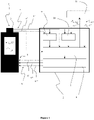
- FIG. 1 shows a schematic of wood stove 1 with a burn controller 2 for controlling a burn in the wood stove 1.
- the wood stove 1 has an exhaust 3 that is equipped with exhaust measure means 4 such as a thermometer 4" and such as a O 2 measuring means 4" like a ⁇ -probe.
- the exhaust 3 is located at the upper end of the wood stove 1.
- the measuring means 4 are connected to the burn controller 2.
- the wood stove 1 has an intake 5 configured to supply air to the wood stove 1.
- the intake is located at the lower end of the wood stove 1.
- the intake 5 is controlled by an intake control 6 from the burn controller 2.
- the intake control in this embodiment has a primary valve control 6', a secondary valve control 6", and a tertiary valve control 6′′′.
- the burn controller 2 has means for storing and executing a burn control algorithm 7 which controls valve controllers 8.
- the burn controller 2 has a wood stove door status means 9 configured to receive input about weather a door 13 is open or closed.
- the burn controller 2 has a thermostatic controller 10 configured to receive input from the thermometer 4' and from a user interface 11 via some user interface communication means 12.
- the burn controller 2 and the user interface 11 are configured to send and receive signals.
- a first signal 12' is a desired temperature or burn level entered via the user interface 11.
- a second signal 12" is a start or stop signal entered via the user interface 11.
- a third signal 12′′′ is a refill signal send from the burn controller 2 to the user interface 11, which refill signal informs that more fuel is needed to maintain the desired temperature or burn cleanliness.
- the wood stove 1 in this embodiment has a door 13 which in this case is a window in front of a combustion chamber 14.
- FIG. 2 shows a wood stove 1 with a combustion chamber 14 with a base 15 and whereto combustion air 16 is fed from a air regulator 17 and wherefrom a flue gas exhaust 18 guided away.
- the wood stove 1 has the air regulator 17 positioned at the lower part of the wood stove below the base 15 of the combustion chamber 14.
- the air regulator 17 has a number of valves 19 each connected via an air duct 20 to conduct combustion air 16 from the outside of the combustion chamber 14 to inside the combustion chamber 14.
- the air regulator 17 has a primary valve 19' that controls the flow of combustion air 16' through a primary air duct 20' from the intake 5 to the lower part of the combustion chamber 14.
- the primary air duct 20' is adapted to guide combustion air 16' through the base 15.
- the air regulator 17 has a secondary valve 19" that controls the flow of combustion air 16" through a secondary air duct 20" from the intake 5 to the middle part of the combustion chamber 14.
- the secondary air duct 20" is adapted to guide combustion air 16" to the rear side of the combustion chamber 14, which rear sided is opposite the window or door 13.
- the air regulator 17 has a tertiary valve 19′′′ that controls the flow of combustion air 16′′′ through a tertiary air duct 20′′′ from the intake 5 to the upper part of the combustion chamber 14.
- the tertiary air duct 20" is adapted to guide combustion air 16′′′ to the front side of the combustion chamber 14, which front side is the same side as the door or window 13.
- the wood stove 1 has connection means for connecting the exhaust 3 or connection to a chimney 21.
- the exhaust measure means 4 are positioned inside the chimney 21.
- the exhaust measure means 4 includes a thermometer 4' and a ⁇ -probe as the O 2 -measurement means 4".
- Figure 3 shows an example of a state diagram for controlling the burn in a wood stove 1.
- the state diagram is embedded in the burn controller 2 as a software programme and in particular as burn control algorithm 7.
- the state diagram or state controller has a set of start instructions 100 followed by five states during operation.
- the five states include a 4 th state 101, 0 th state 102, a 1 st state 103, a 2 nd state 104, and a 3 rd state 105.
- the 0 th state is a cold start state 102 where the wood stove 1 is cold meaning.
- the 1 st state is a warm start state 103 where the wood stove 1 has been operated and is still warm.
- the 2 nd state is a combustion state 104 where the fuel burns in the wood stove 1.
- the 3 rd state is a glow state 105 where the fuel glows in the wood stove 1.
- the 4 th state is an off state 101 where the wood stove 1 is closed down and the fuel burn is terminated.
- the burn controller 2 controls valves 19 in the air regulator 19.
- the burn controller 2 is configured to receive input from exhaust measures 4 and in this case from a user interface 11 which measures and inputs are used to determine when the state controller shall make a shift or a transition from one state to the same, "a reset", or another state.
- 4-1 shift 111 is a shift or transition from the 4th state 101 to the 0 th state 102 or from the start state to the OFF-state.
- 0-0 shift 112 is a shift or transition from the 0 th state 102 to the 0 th state 102 or from the cold start state to the cold start state. Such shift or transition from and to the same state is performed if the procedure in the state is not finished or need to be restarted.
- 0-1 shift 113 is a shift or transition from the 0 th state 102 to the 1 st state 103 or from the cold start state to the warm state.
- 1-1 shift 114 is a shift or transition from the 1st state 103 to the 1st state 103 or from the warm state to the warm state.
- 1-2 shift 115 is a shift or transition from the 1st state 103 to the 2nd state 104 or from the warm state to the combustion state.
- 1-3 shift 116 is a shift or transition from the 1st state 103 to the 3rd state 105 or from the warm state to the glow state.
- shift 117 is a shift or transition from the 2nd state 104 to the 1st state 103 or from the combustion state to the warm state.
- 2-3 shift 118 is a shift or transition from the 2nd state 104 to the 3rd state 105 or from the combustion state to the glow state.
- 3-1 shift 119 is a shift or transition from the 3rd state 105 to the 1st state 103 or from the glow state to the warm state.
- 3-4 shift 120 is a shift or transition from the 3rd state 105 to the 4th state 101 or from the glow state to the off state.
- Figures 4 through 13 illustrate valve control schemes for each of the states 0 th 101, 1 st 102, 2 nd 103, 3 rd 104, and 4 th 105 states. Each state is controlled at least one valve control scheme depending on the previous state.
- the control schemes shown in Figures 4 to 8 relate to an embodiment of the invention, in which the primary, secondary and tertiary air ducts are controllable by means of respective valves 19, 19', 19", 19′′′, and Figures 8 to 13 relate to an embodiment of the invention, in which only the primary and secondary air ducts are controlled by means of respective valves, while the tertiary air duct is kept at a constant position.
- Each scheme has an initial value, a PD controller input and a set point value for each of the primary, secondary, and, where applicable, tertiary valves.
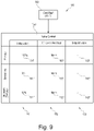
- FIGS 4 and 9 show an example of a cold start phase 102, the 0 th state, with a cold start control 130 that includes a cold start valve control scheme 150.
- the cold start valve control scheme 150 has initial values 151, PD controller input values 152, and set point values 153 for each of the primary, secondary, and tertiary valves.
- tertiary initial value 151′′′ which in the instance of Fig. 4 is 100 % resulting in that the tertiary valve 19′′′ is 100 % opened for a maximum intake of tertiary combustion air 16" to the combustion chamber 14.
- the tertiary initial value is fixed at 50% opened.
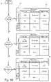
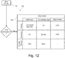
- Figures 5 and 10 show an example of a warm start phase 103, the 1 st state or phase, with a warm start control 131 that includes a cold to warm start valve control scheme 160, a combustion to warm valve control scheme 161, and a glow to warm valve control scheme 162.
- the cold to warm start valve control scheme 160 has: A primary initial value of 100 % resulting in that the primary valve 19' is fully opened for delivering a maximum of primary combustion air 16' to the combustion chamber 14.
- the regulator is based on a primary set point value Tset according to for example a user input via the user interface or a preset standard desirable temperature.
- a tertiary initial value of 100 % results in that the tertiary valve 19′′′ is fully opened for delivering a maximum of tertiary combustion air 16′′′ to the combustion chamber 14.
- the tertiary initial value is fixed at 50% opened.
- a tertiary controller input that is left unregulated or floating and with a null nor irrelevant set point value.
- the combustion to warm start valve control scheme 161 has: A primary initial value of 20 % ( Fig. 5 ) resulting in that the primary valve 19' is 20 % open for delivering some primary combustion air 16' to the combustion chamber 14.
- the primary initial value is between 0% (i.e. closed) and 50%.
- tertiary controller input that is left unregulated or floating and with a null nor irrelevant set point value resulting in that the tertiary valve 19′′′ is left at the initial value ( Fig. 5 ).
- the tertiary initial value is fixed at 50% in Fig. 10 .
- the glow to warm start valve control scheme 162 has: A primary initial value of 20 % resulting in that the primary valve 19' is 20 % open for delivering some primary combustion air 16' to the combustion chamber 14. In Fig. 10 , the primary initial value is between 25 and 50%.
- a secondary controller input that regulates the Oxygen level towards a secondary set point value of 11.5 % O 2 .
- the secondary oxygen set point value is 8.5% O 2 .
- tertiary initial value 100 % ( Fig. 5 ) resulting in that the tertiary valve 19′′′ is fully open for delivering a maximum of secondary combustion air 16′′′ to the combustion chamber 14.
- the tertiary initial value remains fixed at 50%.
- tertiary controller input that is left unregulated or floating and with a null nor irrelevant set point value resulting in that the tertiary valve 19′′′ is left at the initial value.
- the warm start control 131 is further configured for determining the previous state thereby enabling the desired selection of the valve control scheme 160, 161, 162.
- Figures 6 and 11 show examples of a combustion state 104, the 2 nd state, and a combustion control 132 controlling a first warm to combustion valve control scheme 170 and a subsequent warm to combustion valve control scheme 171.
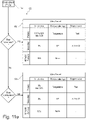
- the combustion state of Fig. 11 is a first combustion state, whereas a second combustion state is described below with reference to Fig. 11a .
- the first warm to combustion valve control scheme 170 has: A primary initial value of 0 % resulting in that the primary valve 19' is fully closed for delivering zero primary combustion air 16' to the combustion chamber 14.
- a tertiary initial value of 100 % results in that the tertiary valve 19′′′ is fully opened for delivering a maximum of tertiary combustion air 16′′′ to the combustion chamber 14.
- the tertiary initial value remains fixed at 50%.
- a tertiary controller input that regulates temperature towards a temperature determined by a tertiary set point value Tset, whereas no controller input is provided in the embodiment of Fig. 11 .
- the subsequent warm to combustion valve control scheme 171 has: A primary initial value of 0 % resulting in that the primary valve 19' is fully closed for delivering zero primary combustion air 16' to the combustion chamber 14 ( Figs. 6 and 11 alike).
- a tertiary initial value of 100 % results in that the tertiary valve 19′′′ is fully opened for delivering a maximum of secondary combustion air 16′′′ to the combustion chamber 14.
- the tertiary initial value remains fixed at 50%.
- a tertiary controller input is provided for regulating temperature towards a temperature determined by a tertiary set point value Tset.
- Figs. 7 and 12 show examples of a glow state 105, the 3 rd state, and a glow state control 133 that controls a warm start to glow valve control scheme 180 and a combustion to glow valve control scheme 181.
- Fig. 11a shows second combustion phase, i.e .phase 3a.
- the warm start to glow valve control scheme 180 of Fig. 11a includes the following: A primary initial value that is left unchanged and with a maximum of 50 % resulting in that the primary valve 19' is at maximum half opened for delivering half primary combustion air 16' to the combustion chamber 14 as a maximum.
- Tset There is a primary controller regulates temperature towards a primary set point value determined by Tset.
- the combustion I state to glow valve control scheme 181 of Fig. 11a includes the following: A primary initial value that is 0 % resulting in that the primary valve 19' is closed for delivering no primary combustion air 16' to the combustion chamber 14.
- Tset There is a primary controller regulates temperature towards a primary set point value determined by Tset.
- the warm start to glow valve control scheme 180 includes the following: A primary initial value that is left unchanged and with a maximum of 50 % resulting in that the primary valve 19' is at maximum half opened for delivering half primary combustion air 16' to the combustion chamber 14 as a maximum.
- a primary controller regulates temperature towards a primary set point value determined by Tset ( Fig. 7 ) and that regulates oxygen towards an O 2 level of 8.5% ( Fig. 12 ).
- a tertiary initial value of that is left unchanged with a minimum of 10 % resulting in that the tertiary valve 19′′′ is opened for delivering smal amounts of tertiary combustion air 16′′′ to the combustion chamber 14.
- the tertiary value remains fixed at 50%.
- the combustion state to glow valve control scheme 181 ( Fig. 7 embodiment only) includes the following: A primary initial value that is 0 % resulting in that the primary valve 19' is closed for delivering no primary combustion air 16' to the combustion chamber 14.
- Tset There is a primary controller regulates temperature towards a primary set point value determined by Tset.
- Figures 8 and 13 show examples of an OFF-state 105, the 4 th state, and a OFF state control 134 that controls a combustion to glow valve control scheme 190.
- tertiary initial value 10 % resulting in that the tertiary valve 19′′′ is a slightly open for a delivery of small amounts of tertiary combustion air 16′′′ to the combustion chamber 14.
- the tertiary initial value remains fixed at 50%. However, in order to avoid heat from the surrounding room to dissipate into the cooled-down stove through the tertiary air duct, it may be closed to 0% in the off state.
- a tertiary controller input regulating temperature if the temperature is below 50 degrees Celsius. Thereby remaining fuel is slowly extinguished.
- the tertiary set point value is null.
- Figure 9 shows an embodiment of an air regulator 17 with three valves 19: a primary valve 19', a secondary valve 19", and a tertiary valve 19′′′.
- the air regulating box 17 has a housing 200 with a intake connection means 201 and is formed to fit into a wood stove 1 so that the intake connection means 201 gets combustion air 16 from the intake 5.
- the air regulator 17 has air duct connection means 202 for each valve 19.
- a primary air duct connection means 202' for connecting the air box 17 to a primary air duct 20' allowing combustion air 16 from the intake 5 to be fed the combustion chamber 14 as primary combustion air 16' controlled by the primary valve 19'.
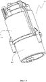
- FIG 10 shows and embodiment of a valve 19 which is a cylinder valve 210 with a valve housing 211 and a valve piston 212.
- the valve piston 212 is in extended to a position furthest out of the valve housing 211.
- Figures 11 shows sectional view of an air box 17 with and two cylinder valves 210, one of which is seen in a cross sectional view. In both cases the valve pistion 212 is withdrawn into the valve housing 211.
- valve piston 212 The movement of the valve piston 212 is done via an actuator connector 213 connected to a actuator means 214.
- the actuator connector 213 and actuator means combination is a shredded linear line that is rotated by a motor thereby linearly moving and positioning the valve piston 212 within the housing 200 to form a valve port 215 due to interaction or relative positioning against a valve port frame 216.
- Figure 12 shows a cross sectional view of a cylinder valve 210 with the valve housing 211, the valve piston 212 linearly movable in and out of the valve housing 211.
- the movement of the valve piston 212 is done along the actuator connector 213, which in this case is a screw that can be rotated by a motor as the actuator means 214.
- the actuator means 214 is controlled by the valve control 6 and the arrangement with the calibrated, in particular the relative positioning of the valve port frame 216, the valve housing 211 and the valve piston 212 so that a signal of 100 % open to the valve control 6 results in a withdrawal of the valve piston 212 into the valve housing 211 thereby making a maximum valve port 215 opening.
- valve control 6 Likewise a signal of 0 % open (close) to the valve control 6 results in a valve piston 212 out of the valve housing 211 and closing towards the valve port frame 216.
- valve port frame 216 has a V-shaped opening so that the size of the valve port 15 opening can be controlled more precisely allowing for a finer control of smaller vale port 15 openings.
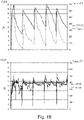
- Figure 13 shows the temperature of exhaust and the CO 2 %-level in the exhaust for a wood stove without the burn controller and air regulator, A, and for a wood stove with the burn controller, B.
- Each diagram shows the timely development of the temperature of the exhaust Texhaust on a scale from 0-700°C and the percentage CO 2 level in the exhaust on a scale from 0-20 %.
- the test has carried out as a standard test according to EN13240 to be able to compare the a burn of a fuel in a standard wood stove with an embodiment of wood stove as disclosed in the case where standard wood stove is fitted with a air regulator, a burn controller and exhaust measures (albeit the O2 sensor being replaced with an eqivalent CO2 sensor).
- the best user is a laborant, best compromise for the chimney and installation, and best possible fuel load (in moist and weight distribution).
- each spike in the figures represents a refuelling of the wood stove. It is clearly observed that the controlled or regulated burn is more constant. Although there are spikes present, these are narrow.
- the T exhaust is very stable at about 380°C.
- the standard test shows that the controlled wood stove according to an embodiment of the invention results in a reduction in fuel consumption of about 15-30 %.
- the controlled wood stove gives an ease of use with a more stable (i.e. less modulation) room temperature with less refills of wood. No or reduced chances of overheating and consequently a reduced risk of damage to the wood stove and therefore a longer life expectancy of the wood stove.
- the controlled wood stove furthermore results in less build-up of soot in the wood stove and the chimney.
Landscapes
- Engineering & Computer Science (AREA)
- Chemical & Material Sciences (AREA)
- Combustion & Propulsion (AREA)
- Mechanical Engineering (AREA)
- General Engineering & Computer Science (AREA)
- Solid-Fuel Combustion (AREA)
- Regulation And Control Of Combustion (AREA)
Applications Claiming Priority (3)
| Application Number | Priority Date | Filing Date | Title |
|---|---|---|---|
| DKPA201170606A DK177394B1 (da) | 2011-11-07 | 2011-11-07 | Fremgangsmåde til forbrænding af et brændsel i en brændeovn, en brændeovn med en styreenhed samt en luftregulator til en brændeovn |
| PCT/DK2012/050409 WO2013068015A1 (fr) | 2011-11-07 | 2012-11-07 | Procédé pour brûler un combustible dans un poêle à bois, poêle à bois doté d'un dispositif de commande ; et régulateur d'air pour un poêle à bois |
| EP12848418.5A EP2776761B1 (fr) | 2011-11-07 | 2012-11-07 | Procédé pour brûler un combustible dans un poêle à bois et poêle à bois doté d'un dispositif de commande |
Related Parent Applications (1)
| Application Number | Title | Priority Date | Filing Date |
|---|---|---|---|
| EP12848418.5A Division EP2776761B1 (fr) | 2011-11-07 | 2012-11-07 | Procédé pour brûler un combustible dans un poêle à bois et poêle à bois doté d'un dispositif de commande |
Publications (4)
| Publication Number | Publication Date |
|---|---|
| EP4012261A2 true EP4012261A2 (fr) | 2022-06-15 |
| EP4012261A3 EP4012261A3 (fr) | 2022-10-12 |
| EP4012261C0 EP4012261C0 (fr) | 2025-01-08 |
| EP4012261B1 EP4012261B1 (fr) | 2025-01-08 |
Family
ID=47878302
Family Applications (2)
| Application Number | Title | Priority Date | Filing Date |
|---|---|---|---|
| EP12848418.5A Active EP2776761B1 (fr) | 2011-11-07 | 2012-11-07 | Procédé pour brûler un combustible dans un poêle à bois et poêle à bois doté d'un dispositif de commande |
| EP22150605.8A Active EP4012261B1 (fr) | 2011-11-07 | 2012-11-07 | Régulateur d'air pour un poêle à bois, kit comprenant un régulateur d'air pour un poêle à bois et un régulateur de combustion, procédé pour fabriquer un poêle à bois, et poêle à bois |
Family Applications Before (1)
| Application Number | Title | Priority Date | Filing Date |
|---|---|---|---|
| EP12848418.5A Active EP2776761B1 (fr) | 2011-11-07 | 2012-11-07 | Procédé pour brûler un combustible dans un poêle à bois et poêle à bois doté d'un dispositif de commande |
Country Status (4)
| Country | Link |
|---|---|
| US (1) | US9803870B2 (fr) |
| EP (2) | EP2776761B1 (fr) |
| DK (2) | DK177394B1 (fr) |
| WO (1) | WO2013068015A1 (fr) |
Families Citing this family (10)
| Publication number | Priority date | Publication date | Assignee | Title |
|---|---|---|---|---|
| BE1022253B1 (nl) * | 2014-01-22 | 2016-03-04 | Ifire Bvba | Inbouwhaard |
| GB2530732A (en) * | 2014-09-30 | 2016-04-06 | Be Modern Ltd | Solid fuel stove |
| CN105605606A (zh) * | 2015-12-23 | 2016-05-25 | 华中科技大学 | 一种降低电站煤粉锅炉NOx排放浓度的周界风方法 |
| FR3050012B1 (fr) * | 2016-04-06 | 2018-04-13 | Speeta | Poele a bois avec six etats de controle de combustion |
| US11079114B2 (en) * | 2016-11-16 | 2021-08-03 | United States Stove Company | Plate steel single burn rate wood heater with improved emissions |
| US10995945B2 (en) * | 2017-08-10 | 2021-05-04 | United States Stove Company | Biomass pellet combustion system |
| CA3111102A1 (fr) * | 2020-03-06 | 2021-09-06 | Wolf Steel Ltd. | Systeme de commande pour un appareil bruleur de carburant et methode d'exploitation d'un tel appareil |
| DE102020109358A1 (de) | 2020-04-03 | 2021-10-07 | Ulrich Brunner Ofen- und Heiztechnik Gesellschaft für Guß- und Stahlkonstruktionen mbH | Verfahren zum Regeln einer Verbrennung von Brennstoff in einer Einzelfeuerstätte |
| NO348238B1 (en) * | 2021-12-23 | 2024-10-21 | Pipe Eksperten AS | A chimney control assembly for optimizing the combustion process in a fuel burning heating device and a method for optimizing the combustion process in a fuel burning heating device |
| WO2025230782A1 (fr) * | 2024-04-22 | 2025-11-06 | Aprovecho Research Center | Systèmes d'alimentation en air pour la combustion de combustibles de biomasse chargés par lots |
Citations (1)
| Publication number | Priority date | Publication date | Assignee | Title |
|---|---|---|---|---|
| EP2085694A2 (fr) | 2008-01-30 | 2009-08-05 | HWAM Holding A/S | Poêle à bois commandé électroniquement |
Family Cites Families (16)
| Publication number | Priority date | Publication date | Assignee | Title |
|---|---|---|---|---|
| US4556044A (en) | 1982-06-18 | 1985-12-03 | Barsness Gerald H | Wood and coal burning stove |
| US4832000A (en) | 1982-08-05 | 1989-05-23 | Lamppa Herbert R | Wood-burning stove |
| US4643165A (en) | 1986-02-26 | 1987-02-17 | Chamberlain Joseph G | Nonpolluting, high efficiency firebox for wood burning stove |
| DE8706650U1 (de) * | 1987-02-18 | 1987-07-16 | Brunner, Ulrich, 8382 Arnstorf | Feuerungsofen mit einer automatischen Steuerung der Verbrennungsluftzufuhr |
| DE3705153A1 (de) * | 1987-02-18 | 1988-09-08 | Ulrich Brunner | Feuerungsofen |
| US5113843A (en) | 1991-04-01 | 1992-05-19 | Alladin Steel Products | Combustion device for stoves and fireplaces |
| AT398483B (de) | 1992-12-22 | 1994-12-27 | Pfisterer Kurt | Vorrichtung zur regelung der verbrennungsluftzufuhr bei einem ofen |
| US5666889A (en) | 1995-03-27 | 1997-09-16 | Lennox Industries Inc. | Apparatus and method for furnace combustion control |
| EP1084370B1 (fr) * | 1998-05-29 | 2003-08-13 | Morso Jernstoberi A/S | Fourneau a combustible solide |
| GB2389414B (en) * | 2002-06-06 | 2005-09-28 | A J Wells & Sons | Stove |
| US20070289589A1 (en) | 2006-06-15 | 2007-12-20 | Mcfarland Daniel T | Intelligent and adaptive control system and method for wood burning stove |
| DE102006046599B4 (de) | 2006-09-30 | 2012-02-09 | Hochschule Karlsruhe-Technik Und Wirtschaft | Verfahren und Vorrichtung zur diskontinuierlichen Verbrennung von Brennstoffen |
| EP1918637A1 (fr) | 2006-10-27 | 2008-05-07 | Karl Stefan Riener | Contrôle d'un four à biomasse |
| US20090211565A1 (en) * | 2008-02-27 | 2009-08-27 | Eric Dufour | Fireplace firewood retainer assembly with air deflector, fireplace incorporating the same and method of reducing particulate emissions in a wood burning fireplace |
| DE102009012905B3 (de) * | 2009-03-12 | 2010-01-21 | Global Mind Network Gmbh | Verfahren zur Regelung der Leistung eines Festbrennstoffofens und Ofen mit einer entsprechenden Leistungsregelung |
| FR2945105B1 (fr) * | 2009-04-30 | 2011-07-29 | Brisach | Dispositif de commande de l'alimentation en air d'un poele |
-
2011
- 2011-11-07 DK DKPA201170606A patent/DK177394B1/da active
-
2012
- 2012-11-07 US US14/356,835 patent/US9803870B2/en active Active
- 2012-11-07 DK DK12848418.5T patent/DK2776761T3/da active
- 2012-11-07 EP EP12848418.5A patent/EP2776761B1/fr active Active
- 2012-11-07 EP EP22150605.8A patent/EP4012261B1/fr active Active
- 2012-11-07 WO PCT/DK2012/050409 patent/WO2013068015A1/fr not_active Ceased
Patent Citations (1)
| Publication number | Priority date | Publication date | Assignee | Title |
|---|---|---|---|---|
| EP2085694A2 (fr) | 2008-01-30 | 2009-08-05 | HWAM Holding A/S | Poêle à bois commandé électroniquement |
Also Published As
| Publication number | Publication date |
|---|---|
| US20140315137A1 (en) | 2014-10-23 |
| EP2776761A4 (fr) | 2015-11-25 |
| DK2776761T3 (en) | 2022-04-19 |
| EP2776761B1 (fr) | 2022-01-12 |
| EP4012261A3 (fr) | 2022-10-12 |
| US9803870B2 (en) | 2017-10-31 |
| EP4012261C0 (fr) | 2025-01-08 |
| EP2776761A1 (fr) | 2014-09-17 |
| EP4012261B1 (fr) | 2025-01-08 |
| WO2013068015A1 (fr) | 2013-05-16 |
| DK177394B1 (da) | 2013-03-18 |
Similar Documents
| Publication | Publication Date | Title |
|---|---|---|
| US9803870B2 (en) | Method for burning a fuel in a wood stove, a wood stove with a controller; and an air regulator for a wood stove | |
| US10648739B2 (en) | Controller with clinker agitator control for biofuel-fired furnace | |
| US10337747B2 (en) | Selectable efficiency versus comfort for modulating furnace | |
| US20140311477A1 (en) | Control system for monitoring and adjusting combustion performance in a cordwood-fired heating appliance | |
| CN108119990B (zh) | 空气源热泵及其控制方法和装置 | |
| US20070289589A1 (en) | Intelligent and adaptive control system and method for wood burning stove | |
| Zemann et al. | Optimal operation of residential heating systems with logwood boiler, buffer storage and solar thermal collector | |
| KR20220089184A (ko) | 열풍로 설비의 운전 시스템 및 그 방법 | |
| US11022305B2 (en) | Control system and method for a solid fuel combustion appliance | |
| US8904971B2 (en) | Method of controlling combustion of gas appliance | |
| US20210356173A1 (en) | System and method for controlling gas consumption by gas-fired water heaters | |
| US20230375183A1 (en) | Electric grill with improved convective heat transfer | |
| WO2023121479A1 (fr) | Ensemble de commande de cheminée permettant de réduire au minimum l'émission de particules dans un dispositif de chauffage à combustion de carburant et procédé permettant de réduire au minimum l'émission de particules dans un dispositif de chauffage à combustion de carburant | |
| US12590703B2 (en) | Electronic closed-loop control device for fireplaces comprising a lower combustion system | |
| JP5557708B2 (ja) | 施設園芸用温風暖房機およびその冷却制御方法 | |
| PL226414B1 (pl) | Elektroniczny system oraz sposób regulacji paleniska zwłaszcza do kotłów i pieców z podajnikiem | |
| KR20260065062A (ko) | 온실 또는 축사의 난방수 순환 제어 시스템 | |
| KR20260065063A (ko) | 온실 또는 축사의 난방수 순환 제어용 펌프작동컨트롤러 | |
| EP2902709B1 (fr) | Procédé multiphase pour commander un écoulement d'air dans le sol d'un foyer de cheminée pour combustibles solides, notamment de bois | |
| DE202007003359U1 (de) | Heizeinrichtung mit Abbrandsteuerung | |
| CA3017167A1 (fr) | Systeme et methode de regulation de la consommation de gaz par des chauffe-eau a gaz | |
| AU6545599A (en) | Control apparatus for a solid fuel heater | |
| JP2016073241A (ja) | 施設園芸用温風暖房機の制御方法 | |
| JP2011047605A (ja) | 温風暖房機の制御装置 |
Legal Events
| Date | Code | Title | Description |
|---|---|---|---|
| PUAI | Public reference made under article 153(3) epc to a published international application that has entered the european phase |
Free format text: ORIGINAL CODE: 0009012 |
|
| STAA | Information on the status of an ep patent application or granted ep patent |
Free format text: STATUS: THE APPLICATION HAS BEEN PUBLISHED |
|
| AC | Divisional application: reference to earlier application |
Ref document number: 2776761 Country of ref document: EP Kind code of ref document: P |
|
| AK | Designated contracting states |
Kind code of ref document: A2 Designated state(s): AL AT BE BG CH CY CZ DE DK EE ES FI FR GB GR HR HU IE IS IT LI LT LU LV MC MK MT NL NO PL PT RO RS SE SI SK SM TR |
|
| PUAL | Search report despatched |
Free format text: ORIGINAL CODE: 0009013 |
|
| AK | Designated contracting states |
Kind code of ref document: A3 Designated state(s): AL AT BE BG CH CY CZ DE DK EE ES FI FR GB GR HR HU IE IS IT LI LT LU LV MC MK MT NL NO PL PT RO RS SE SI SK SM TR |
|
| RIC1 | Information provided on ipc code assigned before grant |
Ipc: F23L 13/06 20060101ALI20220906BHEP Ipc: F24B 5/02 20060101ALI20220906BHEP Ipc: F23N 3/06 20060101ALI20220906BHEP Ipc: F24B 1/02 20060101AFI20220906BHEP |
|
| STAA | Information on the status of an ep patent application or granted ep patent |
Free format text: STATUS: REQUEST FOR EXAMINATION WAS MADE |
|
| 17P | Request for examination filed |
Effective date: 20230412 |
|
| RBV | Designated contracting states (corrected) |
Designated state(s): AL AT BE BG CH CY CZ DE DK EE ES FI FR GB GR HR HU IE IS IT LI LT LU LV MC MK MT NL NO PL PT RO RS SE SI SK SM TR |
|
| STAA | Information on the status of an ep patent application or granted ep patent |
Free format text: STATUS: EXAMINATION IS IN PROGRESS |
|
| 17Q | First examination report despatched |
Effective date: 20240313 |
|
| GRAP | Despatch of communication of intention to grant a patent |
Free format text: ORIGINAL CODE: EPIDOSNIGR1 |
|
| STAA | Information on the status of an ep patent application or granted ep patent |
Free format text: STATUS: GRANT OF PATENT IS INTENDED |
|
| INTG | Intention to grant announced |
Effective date: 20240801 |
|
| GRAS | Grant fee paid |
Free format text: ORIGINAL CODE: EPIDOSNIGR3 |
|
| GRAA | (expected) grant |
Free format text: ORIGINAL CODE: 0009210 |
|
| STAA | Information on the status of an ep patent application or granted ep patent |
Free format text: STATUS: THE PATENT HAS BEEN GRANTED |
|
| AC | Divisional application: reference to earlier application |
Ref document number: 2776761 Country of ref document: EP Kind code of ref document: P |
|
| AK | Designated contracting states |
Kind code of ref document: B1 Designated state(s): AL AT BE BG CH CY CZ DE DK EE ES FI FR GB GR HR HU IE IS IT LI LT LU LV MC MK MT NL NO PL PT RO RS SE SI SK SM TR |
|
| REG | Reference to a national code |
Ref country code: GB Ref legal event code: FG4D |
|
| REG | Reference to a national code |
Ref country code: CH Ref legal event code: EP |
|
| REG | Reference to a national code |
Ref country code: DE Ref legal event code: R096 Ref document number: 602012081321 Country of ref document: DE |
|
| REG | Reference to a national code |
Ref country code: IE Ref legal event code: FG4D |
|
| U01 | Request for unitary effect filed |
Effective date: 20250116 |
|
| U07 | Unitary effect registered |
Designated state(s): AT BE BG DE DK EE FI FR IT LT LU LV MT NL PT RO SE SI Effective date: 20250122 |
|
| PG25 | Lapsed in a contracting state [announced via postgrant information from national office to epo] |
Ref country code: RS Free format text: LAPSE BECAUSE OF FAILURE TO SUBMIT A TRANSLATION OF THE DESCRIPTION OR TO PAY THE FEE WITHIN THE PRESCRIBED TIME-LIMIT Effective date: 20250408 |
|
| PG25 | Lapsed in a contracting state [announced via postgrant information from national office to epo] |
Ref country code: PL Free format text: LAPSE BECAUSE OF FAILURE TO SUBMIT A TRANSLATION OF THE DESCRIPTION OR TO PAY THE FEE WITHIN THE PRESCRIBED TIME-LIMIT Effective date: 20250108 |
|
| PG25 | Lapsed in a contracting state [announced via postgrant information from national office to epo] |
Ref country code: ES Free format text: LAPSE BECAUSE OF FAILURE TO SUBMIT A TRANSLATION OF THE DESCRIPTION OR TO PAY THE FEE WITHIN THE PRESCRIBED TIME-LIMIT Effective date: 20250108 |
|
| PG25 | Lapsed in a contracting state [announced via postgrant information from national office to epo] |
Ref country code: IS Free format text: LAPSE BECAUSE OF FAILURE TO SUBMIT A TRANSLATION OF THE DESCRIPTION OR TO PAY THE FEE WITHIN THE PRESCRIBED TIME-LIMIT Effective date: 20250508 |
|
| PG25 | Lapsed in a contracting state [announced via postgrant information from national office to epo] |
Ref country code: HR Free format text: LAPSE BECAUSE OF FAILURE TO SUBMIT A TRANSLATION OF THE DESCRIPTION OR TO PAY THE FEE WITHIN THE PRESCRIBED TIME-LIMIT Effective date: 20250108 |
|
| PG25 | Lapsed in a contracting state [announced via postgrant information from national office to epo] |
Ref country code: GR Free format text: LAPSE BECAUSE OF FAILURE TO SUBMIT A TRANSLATION OF THE DESCRIPTION OR TO PAY THE FEE WITHIN THE PRESCRIBED TIME-LIMIT Effective date: 20250409 |
|
| PG25 | Lapsed in a contracting state [announced via postgrant information from national office to epo] |
Ref country code: SM Free format text: LAPSE BECAUSE OF FAILURE TO SUBMIT A TRANSLATION OF THE DESCRIPTION OR TO PAY THE FEE WITHIN THE PRESCRIBED TIME-LIMIT Effective date: 20250108 |
|
| PG25 | Lapsed in a contracting state [announced via postgrant information from national office to epo] |
Ref country code: CZ Free format text: LAPSE BECAUSE OF FAILURE TO SUBMIT A TRANSLATION OF THE DESCRIPTION OR TO PAY THE FEE WITHIN THE PRESCRIBED TIME-LIMIT Effective date: 20250108 |
|
| PG25 | Lapsed in a contracting state [announced via postgrant information from national office to epo] |
Ref country code: SK Free format text: LAPSE BECAUSE OF FAILURE TO SUBMIT A TRANSLATION OF THE DESCRIPTION OR TO PAY THE FEE WITHIN THE PRESCRIBED TIME-LIMIT Effective date: 20250108 |
|
| PLBE | No opposition filed within time limit |
Free format text: ORIGINAL CODE: 0009261 |
|
| STAA | Information on the status of an ep patent application or granted ep patent |
Free format text: STATUS: NO OPPOSITION FILED WITHIN TIME LIMIT |
|
| 26N | No opposition filed |
Effective date: 20251009 |
|
| U20 | Renewal fee for the european patent with unitary effect paid |
Year of fee payment: 14 Effective date: 20251201 |
|
| PGFP | Annual fee paid to national office [announced via postgrant information from national office to epo] |
Ref country code: GB Payment date: 20251117 Year of fee payment: 14 |
|
| PGFP | Annual fee paid to national office [announced via postgrant information from national office to epo] |
Ref country code: NO Payment date: 20251120 Year of fee payment: 14 |