EP4012376A1 - Dispositif et procédé de détermination d'une concentration des particules prédéterminées en fonction de leurs propriétés morphologiques dans l'air - Google Patents
Dispositif et procédé de détermination d'une concentration des particules prédéterminées en fonction de leurs propriétés morphologiques dans l'air Download PDFInfo
- Publication number
- EP4012376A1 EP4012376A1 EP21209885.9A EP21209885A EP4012376A1 EP 4012376 A1 EP4012376 A1 EP 4012376A1 EP 21209885 A EP21209885 A EP 21209885A EP 4012376 A1 EP4012376 A1 EP 4012376A1
- Authority
- EP
- European Patent Office
- Prior art keywords
- particles
- predetermined
- fluid
- air
- designed
- Prior art date
- Legal status (The legal status is an assumption and is not a legal conclusion. Google has not performed a legal analysis and makes no representation as to the accuracy of the status listed.)
- Withdrawn
Links
- 239000002245 particle Substances 0.000 title claims abstract description 199
- 230000000877 morphologic effect Effects 0.000 title claims abstract description 24
- 238000000034 method Methods 0.000 title claims description 11
- 239000012530 fluid Substances 0.000 claims abstract description 66
- 239000000443 aerosol Substances 0.000 claims abstract description 43
- 238000003384 imaging method Methods 0.000 claims abstract description 40
- 238000011156 evaluation Methods 0.000 claims abstract description 31
- 241000700605 Viruses Species 0.000 claims abstract description 25
- 238000010894 electron beam technology Methods 0.000 claims description 24
- 238000011045 prefiltration Methods 0.000 claims description 10
- 230000005684 electric field Effects 0.000 claims description 9
- 230000037230 mobility Effects 0.000 claims description 9
- 239000008151 electrolyte solution Substances 0.000 claims description 4
- 230000005540 biological transmission Effects 0.000 claims description 3
- 238000009833 condensation Methods 0.000 claims description 3
- 230000005494 condensation Effects 0.000 claims description 3
- 239000002872 contrast media Substances 0.000 claims description 3
- 238000012545 processing Methods 0.000 claims description 3
- 229910052581 Si3N4 Inorganic materials 0.000 claims description 2
- 239000000463 material Substances 0.000 claims description 2
- HQVNEWCFYHHQES-UHFFFAOYSA-N silicon nitride Chemical compound N12[Si]34N5[Si]62N3[Si]51N64 HQVNEWCFYHHQES-UHFFFAOYSA-N 0.000 claims description 2
- 239000007788 liquid Substances 0.000 description 24
- 244000052769 pathogen Species 0.000 description 16
- 230000001717 pathogenic effect Effects 0.000 description 5
- 238000004458 analytical method Methods 0.000 description 4
- 208000015181 infectious disease Diseases 0.000 description 4
- 239000000428 dust Substances 0.000 description 3
- 238000013473 artificial intelligence Methods 0.000 description 2
- 238000013528 artificial neural network Methods 0.000 description 2
- 201000010099 disease Diseases 0.000 description 2
- 208000037265 diseases, disorders, signs and symptoms Diseases 0.000 description 2
- 238000005516 engineering process Methods 0.000 description 2
- 238000001914 filtration Methods 0.000 description 2
- 238000010249 in-situ analysis Methods 0.000 description 2
- 238000005259 measurement Methods 0.000 description 2
- 239000000243 solution Substances 0.000 description 2
- 230000001960 triggered effect Effects 0.000 description 2
- 238000011144 upstream manufacturing Methods 0.000 description 2
- XLYOFNOQVPJJNP-UHFFFAOYSA-N water Substances O XLYOFNOQVPJJNP-UHFFFAOYSA-N 0.000 description 2
- 241000894006 Bacteria Species 0.000 description 1
- 230000006399 behavior Effects 0.000 description 1
- 230000015572 biosynthetic process Effects 0.000 description 1
- 239000003990 capacitor Substances 0.000 description 1
- 239000000969 carrier Substances 0.000 description 1
- 230000001419 dependent effect Effects 0.000 description 1
- 238000013461 design Methods 0.000 description 1
- 238000011161 development Methods 0.000 description 1
- 230000018109 developmental process Effects 0.000 description 1
- 239000006185 dispersion Substances 0.000 description 1
- 239000003792 electrolyte Substances 0.000 description 1
- 238000013213 extrapolation Methods 0.000 description 1
- 230000002431 foraging effect Effects 0.000 description 1
- 239000008241 heterogeneous mixture Substances 0.000 description 1
- 238000012625 in-situ measurement Methods 0.000 description 1
- 230000002452 interceptive effect Effects 0.000 description 1
- 238000011005 laboratory method Methods 0.000 description 1
- 238000000691 measurement method Methods 0.000 description 1
- 239000012528 membrane Substances 0.000 description 1
- 239000000203 mixture Substances 0.000 description 1
- 238000012544 monitoring process Methods 0.000 description 1
- IYDGMDWEHDFVQI-UHFFFAOYSA-N phosphoric acid;trioxotungsten Chemical compound O=[W](=O)=O.O=[W](=O)=O.O=[W](=O)=O.O=[W](=O)=O.O=[W](=O)=O.O=[W](=O)=O.O=[W](=O)=O.O=[W](=O)=O.O=[W](=O)=O.O=[W](=O)=O.O=[W](=O)=O.O=[W](=O)=O.OP(O)(O)=O IYDGMDWEHDFVQI-UHFFFAOYSA-N 0.000 description 1
- 239000007787 solid Substances 0.000 description 1
- 238000012360 testing method Methods 0.000 description 1
Images
Classifications
-
- G—PHYSICS
- G01—MEASURING; TESTING
- G01N—INVESTIGATING OR ANALYSING MATERIALS BY DETERMINING THEIR CHEMICAL OR PHYSICAL PROPERTIES
- G01N15/00—Investigating characteristics of particles; Investigating permeability, pore-volume or surface-area of porous materials
- G01N15/10—Investigating individual particles
- G01N15/14—Optical investigation techniques, e.g. flow cytometry
- G01N15/1468—Optical investigation techniques, e.g. flow cytometry with spatial resolution of the texture or inner structure of the particle
- G01N15/147—Optical investigation techniques, e.g. flow cytometry with spatial resolution of the texture or inner structure of the particle the analysis being performed on a sample stream
-
- G—PHYSICS
- G01—MEASURING; TESTING
- G01N—INVESTIGATING OR ANALYSING MATERIALS BY DETERMINING THEIR CHEMICAL OR PHYSICAL PROPERTIES
- G01N15/00—Investigating characteristics of particles; Investigating permeability, pore-volume or surface-area of porous materials
- G01N15/06—Investigating concentration of particle suspensions
- G01N15/0606—Investigating concentration of particle suspensions by collecting particles on a support
- G01N15/0618—Investigating concentration of particle suspensions by collecting particles on a support of the filter type
-
- G—PHYSICS
- G01—MEASURING; TESTING
- G01N—INVESTIGATING OR ANALYSING MATERIALS BY DETERMINING THEIR CHEMICAL OR PHYSICAL PROPERTIES
- G01N1/00—Sampling; Preparing specimens for investigation
- G01N1/28—Preparing specimens for investigation including physical details of (bio-)chemical methods covered elsewhere, e.g. G01N33/50, C12Q
- G01N1/40—Concentrating samples
-
- G—PHYSICS
- G01—MEASURING; TESTING
- G01N—INVESTIGATING OR ANALYSING MATERIALS BY DETERMINING THEIR CHEMICAL OR PHYSICAL PROPERTIES
- G01N15/00—Investigating characteristics of particles; Investigating permeability, pore-volume or surface-area of porous materials
- G01N15/10—Investigating individual particles
- G01N15/14—Optical investigation techniques, e.g. flow cytometry
- G01N15/1429—Signal processing
- G01N15/1433—Signal processing using image recognition
-
- G—PHYSICS
- G01—MEASURING; TESTING
- G01N—INVESTIGATING OR ANALYSING MATERIALS BY DETERMINING THEIR CHEMICAL OR PHYSICAL PROPERTIES
- G01N15/00—Investigating characteristics of particles; Investigating permeability, pore-volume or surface-area of porous materials
- G01N15/10—Investigating individual particles
- G01N15/14—Optical investigation techniques, e.g. flow cytometry
- G01N15/1456—Optical investigation techniques, e.g. flow cytometry without spatial resolution of the texture or inner structure of the particle, e.g. processing of pulse signals
- G01N15/1459—Optical investigation techniques, e.g. flow cytometry without spatial resolution of the texture or inner structure of the particle, e.g. processing of pulse signals the analysis being performed on a sample stream
-
- G—PHYSICS
- G01—MEASURING; TESTING
- G01Q—SCANNING-PROBE TECHNIQUES OR APPARATUS; APPLICATIONS OF SCANNING-PROBE TECHNIQUES, e.g. SCANNING PROBE MICROSCOPY [SPM]
- G01Q30/00—Auxiliary means serving to assist or improve the scanning probe techniques or apparatus, e.g. display or data processing devices
- G01Q30/02—Non-SPM analysing devices, e.g. SEM [Scanning Electron Microscope], spectrometer or optical microscope
-
- G—PHYSICS
- G01—MEASURING; TESTING
- G01Q—SCANNING-PROBE TECHNIQUES OR APPARATUS; APPLICATIONS OF SCANNING-PROBE TECHNIQUES, e.g. SCANNING PROBE MICROSCOPY [SPM]
- G01Q30/00—Auxiliary means serving to assist or improve the scanning probe techniques or apparatus, e.g. display or data processing devices
- G01Q30/04—Display or data processing devices
-
- G—PHYSICS
- G01—MEASURING; TESTING
- G01N—INVESTIGATING OR ANALYSING MATERIALS BY DETERMINING THEIR CHEMICAL OR PHYSICAL PROPERTIES
- G01N15/00—Investigating characteristics of particles; Investigating permeability, pore-volume or surface-area of porous materials
- G01N15/01—Investigating characteristics of particles; Investigating permeability, pore-volume or surface-area of porous materials specially adapted for biological cells, e.g. blood cells
-
- G—PHYSICS
- G01—MEASURING; TESTING
- G01N—INVESTIGATING OR ANALYSING MATERIALS BY DETERMINING THEIR CHEMICAL OR PHYSICAL PROPERTIES
- G01N15/00—Investigating characteristics of particles; Investigating permeability, pore-volume or surface-area of porous materials
- G01N15/06—Investigating concentration of particle suspensions
- G01N15/075—Investigating concentration of particle suspensions by optical means
-
- G—PHYSICS
- G01—MEASURING; TESTING
- G01N—INVESTIGATING OR ANALYSING MATERIALS BY DETERMINING THEIR CHEMICAL OR PHYSICAL PROPERTIES
- G01N15/00—Investigating characteristics of particles; Investigating permeability, pore-volume or surface-area of porous materials
- G01N15/10—Investigating individual particles
- G01N15/14—Optical investigation techniques, e.g. flow cytometry
- G01N2015/1497—Particle shape
Definitions
- the invention relates to a device and an associated method for detecting a concentration of predetermined particles and in particular viruses in the air based on their morphological properties and in particular their appearance or their external appearance.
- the known methods are usually tailored to an individual, very specific virus or generally to an individual specific pathogen and often cannot be used for other pathogens, so that the concentration or the presence of a wide variety of pathogens in the air cannot be determined with such methods.
- an aerosol is a heterogeneous mixture (dispersion) of solid and/or liquid airborne particles in a gas, eg air.
- the suspended particles are called aerosol particles, and such aerosol particles can be, for example, dust, pollen, spores, bacteria or viruses, so that a simple measurement of the aerosol particles and thus an assessment of whether pathogens are present is not readily possible.
- the invention is therefore based on the object of overcoming the aforementioned disadvantages and providing a device and an associated method by means of which the concentration of certain particles and in particular certain viruses in the air can be determined quickly and with great accuracy.
- a device for detecting a concentration of predetermined particles, in particular viruses, in the air is therefore proposed.
- the air includes organic and/or inorganic aerosol particles.
- the device has a supply unit, an imaging unit, an image acquisition unit and an evaluation unit.
- the delivery unit is designed to bind the aerosol particles contained in the air in a fluid, so that the fluid contains the aerosol particles previously contained in the air as particles.
- the fluid is preferably a liquid, although the fluid can also be a gas mixture. It is further provided that the delivery unit is designed, a continuous or evenly clocked flow of fluid along a to provide a predetermined flow path, the fluid flow being able to be conveyed continuously along the flow path, both in the case of a steady and clocked provision.
- the delivery unit is fluidically connected to the imaging unit with respect to the flow path, so that the fluid or the liquid can flow along the flow path from the delivery unit into and through the imaging unit.
- the imaging unit has a sample channel through which the fluid flow can flow in a correspondingly continuous or clocked manner, which sample channel determines the predetermined flow path within the imaging unit.
- the imaging unit is designed to generate an enlarged image of the particles contained in the fluid flowing through the sample channel. Both in the case of continuous and clocked conveyance, there is a fluid containing the particles in the imaging unit, so that an “in situ measurement” or “in situ analysis” can be carried out by enlarging the particles , in which the sample, which is formed by the fluid flowing through the sample channel, can change continuously.
- the image acquisition unit is designed to acquire the image in particular using image technology and to transmit the image in its acquired form to the evaluation unit.
- the evaluation unit is designed to automatically detect morphological properties of the particles shown in the image, to compare the detected morphological properties with morphological properties of the predetermined particles and by comparing a proportion of predetermined particles in the image and the concentration of the predetermined particles in the determine air.
- morphological properties means in particular the appearance of the particles or the viruses, so that the predetermined particles can be distinguished or are distinguished from other particles on the basis of their appearance.
- the number of predetermined particles per predetermined air volume ie, for example, per cubic meter, can be specified as the concentration.
- the evaluation unit can also determine whether certain Particles (viruses) are present, how high the risk of infection is and whether the risk of infection exceeds a predetermined threshold value.
- concentrations of other particles can also be detected.
- concentrations of other particles can also be detected.
- several predetermined particles can also be provided, in which a first predetermined particle corresponds, for example, to a first virus or first pathogen and a second predetermined particle corresponds, for example, to a second virus or second pathogen, so that the evaluation unit can be used to determine which concentrations of the first predetermined particle and the second predetermined particle are present.
- the morphological properties of both or, in the case of several predetermined particles, of all predetermined particles are known in advance and stored in the evaluation unit.
- the evaluation unit can also determine, for example, the concentration of dust in the air, since dust is also just particles in the air.
- an alarm can also be triggered or a signal can be transmitted to systems connected by signal technology, through which or through which a concentration is to be transmitted and, if necessary, a warning of a risk of infection is to be given.
- the basic inventive idea through the device is to provide a way with which a continuous or continuous clocked sample flow (fluid flow) can be continuously analyzed in order to detect and at least display the concentration of viruses (particles) in the (room) air.
- the air can be sucked in with a predetermined volume flow, for example by a suction device and in particular a fan or a blower.
- the supply unit is designed to bind the aerosol particles contained in a predetermined volume of the air in a predetermined volume to the fluid, so that from the proportion the concentration of the predetermined particles in the predetermined volume of air can be determined from predetermined particles in the predetermined volume of the fluid. It is thus the case that predetermined particles preferably contained in a defined air volume are present in the fluid in a defined and known fluid volume after binding.
- the predetermined particles may be present in the fluid at a very low concentration such that the solution of fluid and particles may be very "thin".
- the fluid or liquid is an electrolyte solution, i.e. contains an electrolyte and the supply unit and/or the imaging unit contains a an electric field generating isotachiophoresis device.
- the isotachiophoresis device is designed to separate the particles bound in the electrolyte solution from one another in sections due to their different ion mobilities, so that the fluid flowing through the sample channel has liquid sections in which particles with the same ion mobility are concentrated.
- the predetermined particles are present in a higher concentration than in the surrounding regions of the fluid, and in which substantially all of the predetermined particles of the sample are present because they have identical ion mobility.
- this area In front of and behind this area there are correspondingly further areas in which other particles contained in the sample with different ion mobilities are present in an increased concentration.
- the area of the sample with the increased concentration of the predetermined particles can be enlarged in a targeted manner by the imaging unit, or essentially the entire sample can be enlarged.
- the isotachiophoresis device can also have two voltage clamps, of which a first clamp is arranged fluidically on the inlet side of the imaging unit and a second clamp is arranged fluidically on the outlet side of the imaging unit, through which the fluid within the sample channel can be subjected to voltage or an electric field.
- the device also includes a pump which is designed to drive the fluid flow along the flow path and the liquid or to pump or convey the fluid from the supply unit through the imaging unit with a preferably steady volume flow or clocked in a continuous cycle.
- the supply unit is designed to add a contrast agent to the fluid and preferably to the liquid, by means of which a negative contrast can be implemented in particular, so that the particles or the shape and external appearance of the particles are better visible or recognizable in the image generated by the imaging unit.
- the contrast medium can in particular be phosphotungstic acid.
- the delivery unit has a pre-filter on the inlet side, which is designed to filter air flowing into the delivery unit on the inlet side, so that organic and/or inorganic aerosol particles contained in the air that are not the predetermined particles are involved , At least partially filtered out before the binding of the aerosol particles in the fluid, so that they are not present in the fluid accordingly. Since the most important types of predetermined particles have a diameter of less than 300 nm, size filtering is particularly suitable as a pre-filter, through which essentially all particles are filtered out which have a diameter greater than 300 nm.
- the pre-filter can also have a number of filters, which can also be based on different filter principles.
- the pre-filter can have a size filter through which preferably essentially all aerosol particles that have a diameter greater than the diameter of the predetermined particles are filtered out, so that filtered air is obtained which correspondingly preferably only aerosol particles with a diameter equal and/or or smaller than the diameter of the predetermined particles.
- Such a size filter can also consist of several filters arranged one behind the other, so that the size filter can essentially be a filter arrangement through which successive particles with a diameter greater than the diameter of the predetermined particles can be filtered before the remaining Particles are bound in the fluid.
- the pre-filter has a charge filter, through which aerosol particles having a positive charge and/or aerosol particles having a negative charge and/or aerosol particles having no charge are filtered out of the air, so that filtered air is obtained which preferably correspondingly only Contains aerosol particles which have a predetermined charge which corresponds to a charge of the predetermined particles.
- charge can be understood to mean a positive charge, a negative charge and no charge.
- the fluid essentially only contains the aerosol particles previously contained in the filtered air with a predetermined charge as particles, which can be realized, for example, by a linear mass spectrometer with quadruple electrodes.
- an electric field can be used, for example, which deflects the charged (aerosol) particles from their path of movement and thus removes them from the air flow.
- a charge filter implemented in this way can also be combined with one or more size filters.
- the pre-filter has or provides an inhomogeneous electric field, through which polarizable aerosol particles are polarized.
- the inhomogeneous electric field or a device generating this field is designed to direct the polarized aerosol particles to a collecting device or to deflect them from their path of movement and to collect them on the collecting device due to the inhomogeneous course of the electric field.
- the polarized aerosol particles collect accordingly on or at the collection device and are bound to it or starting from this when binding the aerosol particles contained in the air in the fluid.
- the collection device can be the condenser, explained later, of the supply unit and can be temperature-controlled accordingly, so that the polarized aerosol particles condense on the collection device.
- the passage of the air through the inhomogeneous electric field, which essentially results in the filtering and collection of the polarizable particles from the air can be combined with an upstream charge filter and one or more upstream size filters.
- the collection device can also be designed as a correspondingly oppositely charged surface, which attracts the predetermined particles and the previously known charge.
- Such surfaces that are correspondingly oppositely charged and provided as collecting devices can also be heated.
- the supply unit has a condenser for binding the aerosol particles contained in the air in the fluid or the liquid by condensation.
- the air with the particles it contains can therefore condense on the condenser to form a condensate (condensed water) and be discharged by it.
- the condenser can be temperature-controlled, leading to the formation of condensation water, and can be designed, for example, as a Peltier element.
- the imaging unit can particularly advantageously be a transmission electron microscope (TEM), which has an electron source that generates an electron beam, a large number of magnets that direct the electron beam and act as lenses for the electron beam, and a vacuum chamber through which the electron beam passes.
- TEM transmission electron microscope
- the sample channel preferably passes through the vacuum chamber orthogonally to the electron beam or to a longitudinal axis of the electron beam and the electron beam runs through the sample channel and the fluid flowing through the sample channel in particular continuously.
- the sample channel for the electron beam generated by the TEM should be transparent or almost completely permeable be, so that an advantageous variant provides that the sample channel is formed from silicon nitride or another material that is permeable to the electron beam or to the electrons of the electron beam.
- sample channel can consist of one, two or more membrane(s) lying against one another and forming a channel between them.
- the thickness of the sample channel is preferably selected parallel to the electron beam in such a way that the TEM can generate an image or magnification that is as precise and sharp as possible.
- the TEM proposed here can be advantageously designed in such a way that it is specially designed for the enlargement of a constantly changing but similar sample at a previously known and unchangeable position, but no exchange of a sample carrier or the like is necessary for its change.
- the TEM proposed according to the advantageous variant does not have to be designed to be essentially focussing or generally adjustable and also does not have to take into account or enable a change of a specimen slide for the samples.
- the magnets are designed as permanent magnets or as electromagnets and are supplied with a constant or unchanging voltage, so that the electron beam is directed by the magnets in a single predetermined way and is focused on the fluid flowing through the sample channel.
- the magnets can also be provided in the form of coils. Furthermore, these are arranged in particular as ring magnets around the vacuum chamber. If electromagnets are provided with a constant voltage, there is no need for complex voltage regulation and an associated controller.
- a TEM usually includes several magnets or magnet systems formed by them, so that, for example, depending on the required magnetic field, first magnets of the TEM can be embodied as permanent magnets and second magnets of the TEM can be embodied as electromagnets supplied with a constant voltage. If the TEM includes an aperture, this can also be designed to be unchangeable or fixed. The electron source can also be designed to generate an unchangeable or fixed electron beam with consistently predetermined properties.
- the proposed TEM is preferably not significantly adjustable.
- the magnets can be exchangeable or an aperture that may be present can be adjusted to a very limited extent.
- sample channel can be connected to the vacuum chamber permanently and in particular in a stationary manner in relation to the vacuum chamber.
- a one-piece design of the vacuum chamber and sample channel is also advantageous, in which they are inseparably connected.
- the vacuum chamber of the TEM does not have to be designed to repeatedly build up a high vacuum. Therefore, the vacuum chamber can be sealed completely pressure-tight and also be designed to permanently maintain a vacuum prevailing in it, so that a pressure reduction determining the vacuum only has to be carried out once and is then maintained permanently, i.e. preferably over the entire service life of the device.
- the image acquisition unit is preferably a CCD sensor or a camera for acquiring and in particular digitizing the generated image.
- the camera or the CCD sensor is designed to capture the image generated by the imaging unit.
- the image acquisition unit can transmit the image acquired in this way to the evaluation unit electronically or using signals. Both a still image and a moving image, such as a continuous video signal, can be transmitted to the evaluation unit.
- the evaluation unit has, according to an advantageous embodiment, a data memory in which the morphological properties and in particular an appearance of the predetermined particles are stored, for example by an algorithm, in tabular form or as a comparison image.
- the evaluation unit is designed to use image processing and object recognition and, for example, neural networks or artificial intelligence to determine how many of the particles shown in the image have morphological properties and in particular an appearance corresponding to the morphological properties and in particular the appearance of the predetermined particles and are thus predetermined particles. If the number of particles in the sample was thus determined, which are the predetermined particles, the number can be used to determine their proportion or their number in the sample or in the air.
- a further aspect of the invention relates to a method for detecting a concentration of predetermined particles, in particular viruses, in air, which comprises organic and/or inorganic aerosol particles, using a device according to the invention. It is provided that the aerosol particles contained in the air are bound in a fluid with the delivery unit, so that the fluid contains the previously contained in the air Contains aerosol particles as particles, and that then a steady or evenly clocked fluid flow is provided along a predetermined flow path. An enlarged image of the particles contained in the fluid flowing through the sample channel is then generated by means of the imaging unit. The image generated in this way is recorded with the image recording unit and transmitted to the evaluation unit.
- the evaluation unit automatically detects morphological properties of the particles shown in the image, with the morphological properties detected then being compared with morphological properties of the predetermined particles. By the comparison, a proportion of predetermined particles in the map and the concentration of the predetermined particles in the air are determined.
- the recording of the morphological properties of the particles and the subsequent comparison also means in particular a comparison of the image generated by the imaging unit or the images of the particles shown thereon with comparison images of the predetermined particles.
- a further aspect of the invention relates to a system for determining a movement and concentration of predetermined particles in a room in the sense of a room.
- the system includes a central evaluation unit and a large number of devices according to the invention.
- the devices are distributed in the room according to a predetermined pattern and in particular according to a predetermined grid.
- the central evaluation unit which can also include or integrally form the evaluation unit of the devices, is designed to calculate a concentration of the particles in the space and/or a distribution of the predetermined particles in the space and/or a movement from the concentrations determined by the devices to determine and/or predict the predetermined particles in the space.
- the concentrations can also be determined and observed or analyzed over a longer period of time.
- neural networks artificial intelligence or an extrapolation can also be used in particular.
- the movement of the predetermined particles not only the macroscopic movement in a room but also, with a suitable arrangement of the devices, a Brownian molecular movement of the particles can be detected.
- an alarm or signal can also be generated if the predetermined particles in the room, i.e. the aerosol cloud, move in a certain direction or to a certain position.
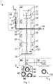
- the figure is schematic by way of example and shows a device 1 which uses a transmission electron microscope (TEM) as the imaging unit 20 .
- TEM transmission electron microscope
- the basic principle of the device 1 is to suck in or absorb air 3 and, for example, room air at an air inlet 2, to bind the particles contained in the air 3 in the supply unit 10 in a liquid 4 as a fluid and to create a constant flow of liquid or fluid provide by the imaging unit 20, so that in this way an "in-situ analysis" of the particles bound in the liquid 4 is made possible, in which the sample to be analyzed, which is the liquid 4 or, more precisely, through the Imaging unit 20 flowing liquid 4 is constantly changing. Together with the liquid 4, a constant stream of particles is thus provided by the TEM or by the imaging unit 20, through which the particles are imaged enlarged, so that the particles contained in the sample or in the liquid 4 can then be analyzed.
- the supply unit 10 has a pre-filter 11, through which particles are filtered out of the air 3, which, because of their size, charge or other factors, cannot be the predetermined particles.
- the pre-filter 11 can have several filter stages and use different filter principles.
- the air 3 filtered by the pre-filter 11 is then condensed by a condenser 12 so that a condensate forms as a liquid 4 in which the particles previously contained in the filtered air 3 are bound.
- the condensate or the liquid 4 is then pumped along a predetermined flow path from the supply unit 10 into or through the imaging unit 20, a pump 60 arranged on the outlet side of the imaging unit 20 being used for this purpose.
- the imaging unit 20 has an isotachiophoresis device with a first voltage clamp 25 and a second voltage clamp 25'.
- the first voltage clamp 25 is arranged on the fluidic input side of the imaging unit 20 or the sample channel 29 and the second voltage clamp 25' is fluidly arranged on the output side of the imaging unit 20 or the sample channel 29, with these building up an electric field in the sample channel 29 so that in the the liquid 4 flowing through the sample channel 29 form a plurality of regions which each have particles with the same or approximately the same ion mobility. Essentially all particles with an ion mobility equal to the ion mobility of the predetermined particles and therefore essentially all predetermined particles are present in one of these areas, so that it is sufficient to image only this area with the imaging unit 20, to capture it with the image acquisition unit 40 or evaluate with the evaluation unit 50.
- the imaging unit 20 presently implemented as a TEM does not have to be designed for different measurement methods or an exchange of sample carriers or the like, so that the TEM is specialized for the present application.
- the TEM has a completely and permanently sealed vacuum chamber 31 in which a vacuum (high vacuum) was generated once and is permanently maintained.
- An electron source 21 emits an electron beam 30 into the vacuum chamber, which can also be referred to as a measuring column, and traverses the length of the vacuum chamber 31 .
- the beam intensity of the electron beam 30 is set invariably by a Wehnelt cylinder 22 and directed or focused through a fixed and non-adjustable aperture 23 and several magnets 24, 26, 27 onto the sample channel 29 and the fluorescent screen 32.
- a first magnet 24 or a first magnet system which can also consist of several magnets, serves as a capacitor magnet system, a second magnet 26 or a second magnet system serves as an object magnet system and a third magnet 27 or a third magnet system, serves as a projection magnet system, these being in the present case designed as permanent magnets and thus unchangeable.
- the liquid 4 flowing through the sample channel 29 is thus always struck by the electron beam 30 in a single predetermined manner and an image of the particles present in the liquid 4 is projected onto the fluorescent screen 32, so that an analogous image is visible there, which can also be seen through the Control window 28 can be viewed.
- the image projected onto the fluorescent screen 32 is captured by the image capture unit 40 , which in the present case is essentially formed by a camera 41 , and the image is thus digitized and then transmitted to the evaluation unit 50 .
- a section 5 of an image captured by the camera 41 is shown as an example, in which a large number of particles are visible.
- four predetermined particles 42, 42', 42" are shown there by way of example, which are only partially visible or hidden. These can also be overlaid by other particles 43, 44.
- Its data memory 51 is stored as a comparison image 6 or as a morphological property of the predetermined particle. With the aid of image processing, the particles in section 5 of the image are now compared with the external appearance 52 of the target particle or the predetermined particle the respective analyzed particle is recognized and counted as a predetermined particle in section 5 in comparison image 6.
- the predetermined particles or viruses can thus be distinguished from other particles by their external appearance or by their external shape almost the same size , so that in a determination based on the Size would be incorrectly recognized as a virus or predetermined particle, but a completely different contour or surface shape, so that it can be correctly classified as no predetermined particle or virus with the presently proposed device.
Landscapes
- Chemical & Material Sciences (AREA)
- Health & Medical Sciences (AREA)
- General Health & Medical Sciences (AREA)
- General Physics & Mathematics (AREA)
- Physics & Mathematics (AREA)
- Pathology (AREA)
- Life Sciences & Earth Sciences (AREA)
- Analytical Chemistry (AREA)
- Biochemistry (AREA)
- Immunology (AREA)
- Dispersion Chemistry (AREA)
- Radiology & Medical Imaging (AREA)
- Nuclear Medicine, Radiotherapy & Molecular Imaging (AREA)
- Engineering & Computer Science (AREA)
- Signal Processing (AREA)
- Apparatus Associated With Microorganisms And Enzymes (AREA)
Applications Claiming Priority (1)
| Application Number | Priority Date | Filing Date | Title |
|---|---|---|---|
| DE102020132574.6A DE102020132574A1 (de) | 2020-12-08 | 2020-12-08 | Vorrichtung und Verfahren zur Erfassung einer Konzentration von vorbestimmten Partikeln anhand ihrer morphologischen Eigenschaften in Luft |
Publications (1)
| Publication Number | Publication Date |
|---|---|
| EP4012376A1 true EP4012376A1 (fr) | 2022-06-15 |
Family
ID=78829300
Family Applications (1)
| Application Number | Title | Priority Date | Filing Date |
|---|---|---|---|
| EP21209885.9A Withdrawn EP4012376A1 (fr) | 2020-12-08 | 2021-11-23 | Dispositif et procédé de détermination d'une concentration des particules prédéterminées en fonction de leurs propriétés morphologiques dans l'air |
Country Status (4)
| Country | Link |
|---|---|
| US (1) | US20220178807A1 (fr) |
| EP (1) | EP4012376A1 (fr) |
| CN (1) | CN114624154A (fr) |
| DE (1) | DE102020132574A1 (fr) |
Families Citing this family (1)
| Publication number | Priority date | Publication date | Assignee | Title |
|---|---|---|---|---|
| DE102021101982A1 (de) * | 2021-01-28 | 2022-07-28 | ebm-papst neo GmbH & Co. KG | Vorrichtung und Verfahren zur Erfassung einer Konzentration von vorbestimmten Partikeln anhand ihrer morphologischen Eigenschaften in Luft |
Citations (4)
| Publication number | Priority date | Publication date | Assignee | Title |
|---|---|---|---|---|
| US20090199623A1 (en) * | 2008-02-06 | 2009-08-13 | Basf Se | Measurement system for the multidimensional aerosol characterization |
| US20110110558A1 (en) * | 2009-11-11 | 2011-05-12 | Liberty Standard, Llc | Apparatus, System, and Method for Automatic Airborne Contaminant Analysis |
| US9846111B2 (en) * | 2015-12-30 | 2017-12-19 | Bio-Rad Laboratories, Inc. | Optical detection system for particles |
| US20190368993A1 (en) * | 2017-02-16 | 2019-12-05 | Koninklijke Philips N.V. | Particle characterization apparatus and method |
Family Cites Families (15)
| Publication number | Priority date | Publication date | Assignee | Title |
|---|---|---|---|---|
| US5106468A (en) * | 1985-12-30 | 1992-04-21 | Exxon Research And Engineering Company | Electrophoretic separation |
| US5282151A (en) * | 1991-02-28 | 1994-01-25 | Particle Measuring Systems, Inc. | Submicron diameter particle detection utilizing high density array |
| GB2394290A (en) * | 2002-10-14 | 2004-04-21 | Boris Zachar Gorbunov | Method and apparatus for counting ions in a sample |
| US20110263044A1 (en) | 2008-07-31 | 2011-10-27 | Eads Deutschland Gmbh | Device and method for the automatic detection of biological particles |
| US9207196B2 (en) * | 2010-11-17 | 2015-12-08 | Vanderbilt University | Transmission electron microscopy for imaging live cells |
| US9196457B2 (en) * | 2011-05-24 | 2015-11-24 | The Trustees Of The University Of Pennsylvania | Flow cells for electron microscope imaging with multiple flow streams |
| EP2887065A1 (fr) | 2013-12-17 | 2015-06-24 | Forest Laboratories Deutschland GmbH | Procédé d'analyse des gaz respiratoires dans les maladies infectieuses |
| DE102016008366A1 (de) | 2016-07-08 | 2018-01-11 | Audi Ag | Klimaanlage für ein Fahrzeug |
| GB2574357B (en) * | 2017-03-10 | 2022-07-20 | Univ California | Mobile microscopy system for air quality monitoring |
| DE102018120362A1 (de) | 2018-08-21 | 2020-02-27 | Horiba Europe Gmbh | Partikelmesssystem mit einer Verdünnungsvorrichtung und Verfahren zur Partikelmessung |
| EP3651182A1 (fr) * | 2018-11-12 | 2020-05-13 | FEI Company | Microscope à particules chargées servant à l'examen d'un échantillon et procédé de détermination d'une aberration dudit microscope à particules chargées |
| KR102204189B1 (ko) * | 2019-01-25 | 2021-01-18 | 한국과학기술원 | 팽창저항성이 우수한 전자현미경용 액상 칩 |
| US11262286B2 (en) * | 2019-04-24 | 2022-03-01 | The Regents Of The University Of California | Label-free bio-aerosol sensing using mobile microscopy and deep learning |
| DE102020120199A1 (de) | 2020-07-30 | 2022-02-03 | Bürkert Werke GmbH & Co. KG | Verfahren zur Erfassung der Konzentration von organischen Partikeln in der Luft sowie Sensor hierfür |
| DE102020124740A1 (de) | 2020-09-23 | 2022-03-24 | ebm-papst neo GmbH & Co. KG | Verfahren zur Erfassung der Konzentration von organischen Partikeln in der Luft sowie Vorrichtung hierfür |
-
2020
- 2020-12-08 DE DE102020132574.6A patent/DE102020132574A1/de active Pending
-
2021
- 2021-11-23 EP EP21209885.9A patent/EP4012376A1/fr not_active Withdrawn
- 2021-12-08 US US17/545,272 patent/US20220178807A1/en not_active Abandoned
- 2021-12-08 CN CN202111489512.5A patent/CN114624154A/zh active Pending
Patent Citations (4)
| Publication number | Priority date | Publication date | Assignee | Title |
|---|---|---|---|---|
| US20090199623A1 (en) * | 2008-02-06 | 2009-08-13 | Basf Se | Measurement system for the multidimensional aerosol characterization |
| US20110110558A1 (en) * | 2009-11-11 | 2011-05-12 | Liberty Standard, Llc | Apparatus, System, and Method for Automatic Airborne Contaminant Analysis |
| US9846111B2 (en) * | 2015-12-30 | 2017-12-19 | Bio-Rad Laboratories, Inc. | Optical detection system for particles |
| US20190368993A1 (en) * | 2017-02-16 | 2019-12-05 | Koninklijke Philips N.V. | Particle characterization apparatus and method |
Also Published As
| Publication number | Publication date |
|---|---|
| US20220178807A1 (en) | 2022-06-09 |
| CN114624154A (zh) | 2022-06-14 |
| DE102020132574A1 (de) | 2022-06-09 |
Similar Documents
| Publication | Publication Date | Title |
|---|---|---|
| EP4036553A1 (fr) | Dispositif et procédé de détermination d'une concentration des particules prédéterminées en fonction de leurs propriétés morphologiques dans l'air | |
| DE69115876T2 (de) | Bildgebender Durchflusszytometer | |
| DE69116126T2 (de) | Bildgebender Durchflusszytometer | |
| DE3716350C2 (fr) | ||
| DE69722942T2 (de) | Detektion gefährlicher schwebender fasern | |
| DE102020124740A1 (de) | Verfahren zur Erfassung der Konzentration von organischen Partikeln in der Luft sowie Vorrichtung hierfür | |
| DE60300172T2 (de) | Vorrichtung und Methode zur Messung von Atemalkohol | |
| EP1467194B2 (fr) | Procédé et dispositif pour la détection, caractérisation et/ou élimination de particules | |
| DE102012008250A1 (de) | Ionenmobilitätsseparator für Massenspektrometer | |
| EP3430565B1 (fr) | Procédé d'évaluation d'objets distribués en segmentant une image de synthèse | |
| EP4012376A1 (fr) | Dispositif et procédé de détermination d'une concentration des particules prédéterminées en fonction de leurs propriétés morphologiques dans l'air | |
| WO2020038658A1 (fr) | Système de mesure de particule pourvu d'un dispositif de dilution et procédé pour la mesure de particules | |
| WO2014198813A1 (fr) | Procédé et dispositif pour déterminer des particules non dissoutes dans un fluide | |
| DE112020001755B4 (de) | Gepulster Kondensationspartikelzähler | |
| DE102021108181B4 (de) | Vorrichtung zur Abbildung von Partikeln, insbesondere Viren, in einer Probe | |
| DE19733297A1 (de) | Berührungslose optische Dickenmessung | |
| DE10239767B4 (de) | Vorrichtung und Verfahren zum Bestimmen des aerodynamischen Verhaltens von Partikeln in Aerosolen | |
| EP3574303A1 (fr) | Procédé et dispositif d'analyse de cellules | |
| EP0088917B1 (fr) | Microsonde par laser pour spécimens solides, à laquelle sont aménagées une optique d'observation, une optique de lumière laser et une optique ionique d'un même côté d'un support de spécimen | |
| AT524348B1 (de) | Verfahren und Vorrichtung zur Partikelmessung | |
| EP3112845A1 (fr) | Procédé d'analyse optique in situ d'un gaz de mesure | |
| DE3921895C2 (de) | Aerosol-Elektrometer und Aerosol-Sensoreinrichtung | |
| DE102015119027A1 (de) | Verfahren und Messeinrichtung zur Bestimmung von Blutkörperchen | |
| DE102006033294A1 (de) | Analyseverfahren für chemische und/oder biologische Proben | |
| DE102008010764A1 (de) | Vorrichtung und Verfahren zur Staubdetektion |
Legal Events
| Date | Code | Title | Description |
|---|---|---|---|
| PUAI | Public reference made under article 153(3) epc to a published international application that has entered the european phase |
Free format text: ORIGINAL CODE: 0009012 |
|
| STAA | Information on the status of an ep patent application or granted ep patent |
Free format text: STATUS: THE APPLICATION HAS BEEN PUBLISHED |
|
| AK | Designated contracting states |
Kind code of ref document: A1 Designated state(s): AL AT BE BG CH CY CZ DE DK EE ES FI FR GB GR HR HU IE IS IT LI LT LU LV MC MK MT NL NO PL PT RO RS SE SI SK SM TR |
|
| STAA | Information on the status of an ep patent application or granted ep patent |
Free format text: STATUS: REQUEST FOR EXAMINATION WAS MADE |
|
| 17P | Request for examination filed |
Effective date: 20221209 |
|
| RBV | Designated contracting states (corrected) |
Designated state(s): AL AT BE BG CH CY CZ DE DK EE ES FI FR GB GR HR HU IE IS IT LI LT LU LV MC MK MT NL NO PL PT RO RS SE SI SK SM TR |
|
| STAA | Information on the status of an ep patent application or granted ep patent |
Free format text: STATUS: THE APPLICATION IS DEEMED TO BE WITHDRAWN |
|
| 18D | Application deemed to be withdrawn |
Effective date: 20240601 |