EP4012841A1 - Assemblage d'un câble électrique à l'aide d'un embout de câble - Google Patents
Assemblage d'un câble électrique à l'aide d'un embout de câble Download PDFInfo
- Publication number
- EP4012841A1 EP4012841A1 EP21213427.4A EP21213427A EP4012841A1 EP 4012841 A1 EP4012841 A1 EP 4012841A1 EP 21213427 A EP21213427 A EP 21213427A EP 4012841 A1 EP4012841 A1 EP 4012841A1
- Authority
- EP
- European Patent Office
- Prior art keywords
- shrink
- cable
- seal
- fitting
- sheathed
- Prior art date
- Legal status (The legal status is an assumption and is not a legal conclusion. Google has not performed a legal analysis and makes no representation as to the accuracy of the status listed.)
- Granted
Links
Images


Classifications
-
- H—ELECTRICITY
- H01—ELECTRIC ELEMENTS
- H01R—ELECTRICALLY-CONDUCTIVE CONNECTIONS; STRUCTURAL ASSOCIATIONS OF A PLURALITY OF MUTUALLY-INSULATED ELECTRICAL CONNECTING ELEMENTS; COUPLING DEVICES; CURRENT COLLECTORS
- H01R4/00—Electrically-conductive connections between two or more conductive members in direct contact, i.e. touching one another; Means for effecting or maintaining such contact; Electrically-conductive connections having two or more spaced connecting locations for conductors and using contact members penetrating insulation
- H01R4/10—Electrically-conductive connections between two or more conductive members in direct contact, i.e. touching one another; Means for effecting or maintaining such contact; Electrically-conductive connections having two or more spaced connecting locations for conductors and using contact members penetrating insulation effected solely by twisting, wrapping, bending, crimping, or other permanent deformation
- H01R4/18—Electrically-conductive connections between two or more conductive members in direct contact, i.e. touching one another; Means for effecting or maintaining such contact; Electrically-conductive connections having two or more spaced connecting locations for conductors and using contact members penetrating insulation effected solely by twisting, wrapping, bending, crimping, or other permanent deformation by crimping
- H01R4/183—Electrically-conductive connections between two or more conductive members in direct contact, i.e. touching one another; Means for effecting or maintaining such contact; Electrically-conductive connections having two or more spaced connecting locations for conductors and using contact members penetrating insulation effected solely by twisting, wrapping, bending, crimping, or other permanent deformation by crimping for cylindrical elongated bodies, e.g. cables having circular cross-section
- H01R4/184—Electrically-conductive connections between two or more conductive members in direct contact, i.e. touching one another; Means for effecting or maintaining such contact; Electrically-conductive connections having two or more spaced connecting locations for conductors and using contact members penetrating insulation effected solely by twisting, wrapping, bending, crimping, or other permanent deformation by crimping for cylindrical elongated bodies, e.g. cables having circular cross-section comprising a U-shaped wire-receiving portion
- H01R4/185—Electrically-conductive connections between two or more conductive members in direct contact, i.e. touching one another; Means for effecting or maintaining such contact; Electrically-conductive connections having two or more spaced connecting locations for conductors and using contact members penetrating insulation effected solely by twisting, wrapping, bending, crimping, or other permanent deformation by crimping for cylindrical elongated bodies, e.g. cables having circular cross-section comprising a U-shaped wire-receiving portion combined with a U-shaped insulation-receiving portion
-
- H—ELECTRICITY
- H01—ELECTRIC ELEMENTS
- H01R—ELECTRICALLY-CONDUCTIVE CONNECTIONS; STRUCTURAL ASSOCIATIONS OF A PLURALITY OF MUTUALLY-INSULATED ELECTRICAL CONNECTING ELEMENTS; COUPLING DEVICES; CURRENT COLLECTORS
- H01R13/00—Details of coupling devices of the kinds covered by groups H01R12/70 or H01R24/00 - H01R33/00
- H01R13/02—Contact members
- H01R13/025—Contact members formed by the conductors of a cable end
-
- H—ELECTRICITY
- H01—ELECTRIC ELEMENTS
- H01R—ELECTRICALLY-CONDUCTIVE CONNECTIONS; STRUCTURAL ASSOCIATIONS OF A PLURALITY OF MUTUALLY-INSULATED ELECTRICAL CONNECTING ELEMENTS; COUPLING DEVICES; CURRENT COLLECTORS
- H01R13/00—Details of coupling devices of the kinds covered by groups H01R12/70 or H01R24/00 - H01R33/00
- H01R13/46—Bases; Cases
- H01R13/502—Bases; Cases composed of different pieces
-
- H—ELECTRICITY
- H01—ELECTRIC ELEMENTS
- H01R—ELECTRICALLY-CONDUCTIVE CONNECTIONS; STRUCTURAL ASSOCIATIONS OF A PLURALITY OF MUTUALLY-INSULATED ELECTRICAL CONNECTING ELEMENTS; COUPLING DEVICES; CURRENT COLLECTORS
- H01R13/00—Details of coupling devices of the kinds covered by groups H01R12/70 or H01R24/00 - H01R33/00
- H01R13/46—Bases; Cases
- H01R13/52—Dustproof, splashproof, drip-proof, waterproof, or flameproof cases
- H01R13/5205—Sealing means between cable and housing, e.g. grommet
-
- H—ELECTRICITY
- H01—ELECTRIC ELEMENTS
- H01R—ELECTRICALLY-CONDUCTIVE CONNECTIONS; STRUCTURAL ASSOCIATIONS OF A PLURALITY OF MUTUALLY-INSULATED ELECTRICAL CONNECTING ELEMENTS; COUPLING DEVICES; CURRENT COLLECTORS
- H01R4/00—Electrically-conductive connections between two or more conductive members in direct contact, i.e. touching one another; Means for effecting or maintaining such contact; Electrically-conductive connections having two or more spaced connecting locations for conductors and using contact members penetrating insulation
- H01R4/70—Insulation of connections
-
- H—ELECTRICITY
- H01—ELECTRIC ELEMENTS
- H01R—ELECTRICALLY-CONDUCTIVE CONNECTIONS; STRUCTURAL ASSOCIATIONS OF A PLURALITY OF MUTUALLY-INSULATED ELECTRICAL CONNECTING ELEMENTS; COUPLING DEVICES; CURRENT COLLECTORS
- H01R43/00—Apparatus or processes specially adapted for manufacturing, assembling, maintaining, or repairing of line connectors or current collectors or for joining electric conductors
- H01R43/04—Apparatus or processes specially adapted for manufacturing, assembling, maintaining, or repairing of line connectors or current collectors or for joining electric conductors for forming connections by deformation, e.g. crimping tool
- H01R43/048—Crimping apparatus or processes
- H01R43/05—Crimping apparatus or processes with wire-insulation stripping
-
- H—ELECTRICITY
- H01—ELECTRIC ELEMENTS
- H01R—ELECTRICALLY-CONDUCTIVE CONNECTIONS; STRUCTURAL ASSOCIATIONS OF A PLURALITY OF MUTUALLY-INSULATED ELECTRICAL CONNECTING ELEMENTS; COUPLING DEVICES; CURRENT COLLECTORS
- H01R43/00—Apparatus or processes specially adapted for manufacturing, assembling, maintaining, or repairing of line connectors or current collectors or for joining electric conductors
- H01R43/18—Apparatus or processes specially adapted for manufacturing, assembling, maintaining, or repairing of line connectors or current collectors or for joining electric conductors for manufacturing bases or cases for contact members
Definitions
- the present description generally relates to an electric cable terminal assembly, for example in the field of connector technology and electric cables in a motor vehicle.
- seals are used, which are disposed on the cable sheath and which ensure the sealing between the cable and the internal walls of the terminal or of the connector housing.
- the conventional rubber seal comprises a first portion having sealing lips which ensure a sealing function, and a second portion is adapted to be fixed to the sheathed wire. More specifically, an insulating part of the metal terminal is forcibly deformed to surround the rubber seal over the entire periphery of the sheathed wire, thereby fixing the rubber seal to the sheathed wire. There is further provided in this prior art document an intermediate part intertwined on the peripheral surface of the seal.
- the assembly of the prior art above has in particular the disadvantage of having an interface part, which increases the cost of the assembly and makes it more complex to manufacture.
- the assembly of the prior art cannot adapt to several cable diameters and does not ensure a good fixing of the seal on the electric wire.
- the crimping can cause severe deformations of the seal. These deformations not only adversely affect the sealing properties, but also have the effect that the minimum requirements in terms of tensile force between the seal and the electric cable are no longer met. Thus, a release of the crimped connection between the electric cable and the seal may occur when handling the cable or when pulling the crimped terminal (for example out of a housing).
- document EP2856568B1 discloses a seal.
- the seal comprises a sealing portion and a shrink-fitting portion, with an additional reinforcing element cooperating with a flange.
- the reinforcing element improves the crimping, "protects” the seal during the crimping and reduces the deformations of the relatively flexible seal.
- the reinforcing element is an additional part which increases the cost of the seal and makes its manufacture more complex.
- One aim of the present disclosure is to respond to the drawbacks of the prior art mentioned above and to improve the cable terminal assemblies and particularly, first of all, to propose an assembly of an electric cable and of a cable terminal, the cable being provided with an outer insulation sheath and at least one conductive strand, and having a sheathed portion and a stripped portion,
- sheathed portion or insulated portion a portion of the cable in which the outer insulation sheath partially or totally covers the at least one conductive strand, and by stripped portion a portion of the cable in which the outer insulation sheath does not cover the at least one conductive strand.
- cable terminal a cable connector arranged to be connected to another cable connector, of the same cable or of another cable.
- the cable has a plurality of conductive strands.
- the shrink-fitting wings are arranged to crimp (or allow crimping of) the seal at the shrink-fitting portion, so as to clamp it vigorously (i.e. firmly).
- the shrink-fitting wings do not overlap when they are crimped on the shrink-fitting portion of the seal.
- shrink-fitting wings are not juxtaposed (also called "O" shrink-fitting).
- the shrink-fitting portion has a shoulder arranged to abut on the sheathed portion of the cable.
- the cable terminal further has a male distal part or a female distal part.
- a first terminal having a male distal part can be connected to a second terminal having a female distal part.
- the present disclosure also relates to a method for crimping a cable terminal on an electric cable, with the following steps:
- the stripped portion is increased, that is to say it has a significant length which is greater than the stripped portion of a conventional cable and/or greater than the shrink-fitting portion of the seal.
- the step of stripping the electric cable so as to form a stripped portion can be replaced by the step of providing the electric cable with the stripped portion.
- the method further has the following step:
- the method further has the following step:
- the method further has the following step:
- Figure 1 represents a side view of an assembly of an electric cable and of a cable terminal according to the present description.
- a cable 1 has an outer insulation sheath 3 and a plurality of conductive strands 2 with a sheathed portion 1g of the cable 1 and a stripped portion 1d of the cable 1.
- the cable 1 has a longitudinal axis XX'.
- An axis YY' is represented in order to delimit the sheathed portion 1g of the cable 1 and the stripped portion 1d of the cable 1.
- the outer insulation sheath 3 is preferably made of plastic material and the conductive strands 2 are preferably made of a conductive material such as copper.
- the outer diameter of the sheath 3 is of 4.8 mm (or between 4 and 5 mm) and the inner diameter of the sheath 3 is of 3.2 mm (or between 3 and 4 mm).
- the conductive strands 2 each have a diameter of 0.32 mm (or between 0.25 mm and 0.35 mm). Note that the conductive strands 2 can each have a different diameter.
- the assembly of the electric cable 1 with an electric cable terminal 10 is represented.
- the terminal 10 has shrink-fitting wings 15.
- the assembly further has a seal 11 with a sealing portion 14 and a shrink-fitting portion 12, wherein the sealing portion 14 of the seal 11 is assembled on the sheathed portion 1g of the cable 1, and the shrink-fitting portion 12 of the seal 11 is assembled directly on the stripped portion 1d of the cable 1.
- the shrink-fitting wings 15 are fully assembled on the shrink-fitting portion 12 of the seal 11.
- the seal 11 has a rotational symmetry and can be easily manufactured by a two-component molding process.
- the seal 11 is made of plastic material, particularly silicone.
- the sealing portion 14 has waves on its outer diameter, which vary between 4.25 mm and 7.2 mm.
- the shrink-fitting portion 12 has a smaller diameter than the sealing portion 14.
- the shrink-fitting portion 12 may have a diameter of 2.3 mm (or between 2 and 3 mm).
- the shrink-fitting portion 12 may have a length of 3.2 mm and the sealing portion may have a length of 4.3 mm.
- the shrink-fitting wings 15 are made of metal, preferably steel, and are connected to a second shrink-fitting portion 16 directly crimped or clamped on the conductive strands 2.
- the second shrink-fitting portion 16 is connected to a distal part 17, which can be male or female, so as to connect the terminal 10 to another compatible distal part 17 of another terminal 10.
- the second shrink-fitting portion 16 and the distal part 17 are made of a conductive material, preferably steel.
- the shrink-fitting portion 12 of the seal 11 is positioned on the stripped portion 1d of the cable 1, so as to be directly in contact with the conductive strands 2.
- the shrink-fitting wings 15 are then clamped on the shrink-fitting portion 12 of the seal 11, and closed on the shrink-fitting portion 12, without the shrink-fitting wings 15 touching each other.
- the shrink-fitting wings 15, preferably two in number, thus fully touch the shrink-fitting portion 12 of the seal 11, but are not juxtaposed on each other. A space of 0.2 mm can thus be present between the shrink-fitting wings 15 at their distal end, when they are closed.
- the seal 11 has an inner shoulder 18 (schematically represented in Figure 4 ) so as to abut on the sheathed portion 1g of the cable 1 during the assembly of the seal 11 on the cable 1.
- This allows ensuring the correct positioning of the seal 11 on the cable 1, and the correct alignment of the shrink-fitting portion 12 on the stripped portion 1d of the cable 1.
- the seal 11 is not damaged (for example by poor positioning of the shrink-fitting wings 15).
- the shoulder 18 is produced at the change in diameter between the shrink-fitting portion 12 and the sealing portion 14 of the seal 11, so as to face the sheathed portion 1g during the introduction of the seal 11 in the cable 1 from the stripped portion 1d, along the longitudinal axis XX'.
- the shoulder 18 abuts against the sheathed portion 1g at the YY' axis.
- the seal 11 also has a flange 19, so as to guide the shrink-fitting wings 15, in particular during the crimping and once crimped.
- Figure 2 represents a top view of the assembly.
- the reference signs are kept as much as possible, in relation to figure 1 .
- the space between the shrink-fitting wings 15 is thus visible in the top view.
- the shrink-fitting wings 15 thus cover 98% of the shrink-fitting portion 12 of the seal 11 in a preferred embodiment.
- the crimping of the second shrink-fitting portion 16 on the conductive strands 2 is represented, as well as the end 2a of the conductive strands 2.
- Figure 3 represents a schematic representation of an electric cable and of the crimping method according to the present description.
- the cable 1 is provided with the stripped portion 1d in which the conductive strands 2 are visible and bare, and the sheathed portion 1g in which the conductive strands 2 are insulated and covered with the outer insulation sheath 3.
- the stripped portion 1d is stripped so as to form a preferably increased stripped portion. In other words, the inner peripheral surface of the shrink-fitting portion 12 will be fully in contact with the stripped portion 1d, once assembled.
- Figure 4 represents the schematic representation of the method with additional steps.
- the seal 11 is provided and inserted into the end of the cable 1, from the stripped portion 1d.
- the shrink-fitting portion 12 of the seal 11 is positioned so that the inner peripheral surface of the shrink-fitting portion 12 is directly and entirely in contact with the stripped portion 1d of the cable 1 without the shrink-fitting portion 12 covering the sheathed portion 1g of the cable 1.
- the sealing portion 14 of the seal 11 is thus positioned at the sheathed portion 1g of the cable 1 without the sealing portion 14 of the seal 11 covering the stripped portion 1d of the cable 1.
- the method may further have the step of abutting the shoulder 18 of the shrink-fitting portion 12 of the seal 11 on the sheathed portion 1g of the cable 1g, at the YY' axis. This allows ensuring the correct positioning of the seal 11 of the terminal 10.
- Figure 5 represents the schematic representation of the method with further additional steps.
- the step of providing the terminal 10 having the shrink-fitting wings 15 and providing the seal 11 having the sealing portion 14 and a shrink-fitting portion 12 is divided into sub-steps of first providing the seal first 11 with the sealing portion 14 and the shrink-fitting portion 12, then providing the shrink-fitting wings 15 integrally formed with the second shrink-fitting portion 16 and the distal part 17.
- the step of crimping the second shrink-fitting portion 16 on the conductive strands 2 is also carried out.
- the electric cable 1 directly with the increased stripped portion 1d, that is to say the step of stripping the electric cable 1 is directly carried out with the correct dimension.
- the stripped portion 1d is directly with the correct stripped dimension.
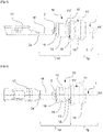
- Figure 6 represents an assembly according to the prior art, as described in document US5824962 .
- the conventional rubber seal 50 comprises a first portion having sealing lips 51 which ensure a sealing function, and a second part 55 is adapted to be fixed to the sheathed wire 52. More specifically, an insulating part 54 of the metal terminal 53 is forcibly deformed to surround the rubber seal over the entire periphery of the sheathed wire 52, thereby fixing the rubber seal to the wire 52. An intermediate part intertwined on the peripheral surface of the seal at the fixing is further provided in this document of the prior art.
- Figure 7 represents a seal according to the prior art, as described in document EP2856568B1 .
- the seal comprises a sealing portion 32 and a shrink-fitting portion 31, with an additional reinforcing element 34 cooperating with a flange 33.
- the reinforcing element improves the crimping, "protects” the seal during the crimping and reduces the deformations of the relatively flexible seal.
Landscapes
- Engineering & Computer Science (AREA)
- Manufacturing & Machinery (AREA)
- Connections Effected By Soldering, Adhesion, Or Permanent Deformation (AREA)
- Manufacturing Of Electrical Connectors (AREA)
Applications Claiming Priority (1)
| Application Number | Priority Date | Filing Date | Title |
|---|---|---|---|
| FR2013077A FR3117690B1 (fr) | 2020-12-11 | 2020-12-11 | assemblage d’un câble électrique avec un terminal de câble |
Publications (2)
| Publication Number | Publication Date |
|---|---|
| EP4012841A1 true EP4012841A1 (fr) | 2022-06-15 |
| EP4012841B1 EP4012841B1 (fr) | 2024-08-28 |
Family
ID=75108461
Family Applications (1)
| Application Number | Title | Priority Date | Filing Date |
|---|---|---|---|
| EP21213427.4A Active EP4012841B1 (fr) | 2020-12-11 | 2021-12-09 | Assemblage d'un câble électrique à l'aide d'un embout de câble |
Country Status (4)
| Country | Link |
|---|---|
| US (1) | US11705647B2 (fr) |
| EP (1) | EP4012841B1 (fr) |
| CN (1) | CN114628928B (fr) |
| FR (1) | FR3117690B1 (fr) |
Citations (4)
| Publication number | Priority date | Publication date | Assignee | Title |
|---|---|---|---|---|
| EP0701300A2 (fr) * | 1994-09-08 | 1996-03-13 | Sumitomo Wiring Systems, Ltd. | Dispositif de fixation bouchon d'étanchéité en caoutchouc et procédé pour le serrer à un fil |
| EP1160930A1 (fr) * | 2000-05-31 | 2001-12-05 | Yazaki Corporation | Dispositif de fixation pour un contact à fiche étanche |
| US20040106316A1 (en) * | 2001-12-04 | 2004-06-03 | Sumitomo Wiring Systems, Ltd. | Waterproof resilient plug |
| EP2856568B1 (fr) | 2012-05-31 | 2018-07-11 | Delphi International Operations Luxembourg S.à r.l. | Joint de fil unique, pour sceller de manière étanche un câble électrique dans une ouverture d'une borne |
Family Cites Families (10)
| Publication number | Priority date | Publication date | Assignee | Title |
|---|---|---|---|---|
| US3555171A (en) * | 1968-07-29 | 1971-01-12 | Robert L Larson | Cable connection insulator and seal |
| US4356343A (en) * | 1980-05-12 | 1982-10-26 | Larson Robert L | Closure and seal for sheathed multi-strand cable ends |
| JP2002343493A (ja) * | 2001-05-18 | 2002-11-29 | Yazaki Corp | 端子一体型シール部材 |
| JP4161847B2 (ja) * | 2003-08-20 | 2008-10-08 | 住友電装株式会社 | ゴム栓 |
| FR2917244B1 (fr) * | 2007-06-06 | 2012-12-21 | Peugeot Citroen Automobiles Sa | Cosse de connexion. |
| EP2254203B1 (fr) * | 2009-04-03 | 2015-05-20 | Sumitomo Wiring Systems, Ltd. | Prise élastique, construction d'épreuve fluide et connecteur |
| JP5391173B2 (ja) * | 2010-09-30 | 2014-01-15 | 古河電気工業株式会社 | 電線と端子の接続構造及び接続装置、接続方法、ワイヤーハーネス |
| FR2984030B1 (fr) * | 2011-12-09 | 2014-10-10 | Electricite De France | Kit et procede de jonction de cables de reseau basse tension |
| JP6926884B2 (ja) * | 2017-09-21 | 2021-08-25 | 株式会社オートネットワーク技術研究所 | 端子付電線 |
| US10741975B2 (en) * | 2018-10-19 | 2020-08-11 | Aptiv Technologies Limited | Sheilded cable assembly and electromagnetic shield terminal assembly for same |
-
2020
- 2020-12-11 FR FR2013077A patent/FR3117690B1/fr active Active
-
2021
- 2021-12-06 US US17/543,252 patent/US11705647B2/en active Active
- 2021-12-08 CN CN202111493690.5A patent/CN114628928B/zh active Active
- 2021-12-09 EP EP21213427.4A patent/EP4012841B1/fr active Active
Patent Citations (5)
| Publication number | Priority date | Publication date | Assignee | Title |
|---|---|---|---|---|
| EP0701300A2 (fr) * | 1994-09-08 | 1996-03-13 | Sumitomo Wiring Systems, Ltd. | Dispositif de fixation bouchon d'étanchéité en caoutchouc et procédé pour le serrer à un fil |
| US5824962A (en) | 1994-09-08 | 1998-10-20 | Sumitomo Wiring Systems, Ltd. | Sealing rubber plug with interposing band under the insulation barrel of a wire terminal |
| EP1160930A1 (fr) * | 2000-05-31 | 2001-12-05 | Yazaki Corporation | Dispositif de fixation pour un contact à fiche étanche |
| US20040106316A1 (en) * | 2001-12-04 | 2004-06-03 | Sumitomo Wiring Systems, Ltd. | Waterproof resilient plug |
| EP2856568B1 (fr) | 2012-05-31 | 2018-07-11 | Delphi International Operations Luxembourg S.à r.l. | Joint de fil unique, pour sceller de manière étanche un câble électrique dans une ouverture d'une borne |
Also Published As
| Publication number | Publication date |
|---|---|
| US11705647B2 (en) | 2023-07-18 |
| CN114628928A (zh) | 2022-06-14 |
| FR3117690B1 (fr) | 2025-06-20 |
| FR3117690A1 (fr) | 2022-06-17 |
| EP4012841B1 (fr) | 2024-08-28 |
| CN114628928B (zh) | 2024-11-08 |
| US20220190491A1 (en) | 2022-06-16 |
Similar Documents
| Publication | Publication Date | Title |
|---|---|---|
| CN1183628C (zh) | 具有模制的应力消除件的电缆总成及其制造方法 | |
| CN101505999B (zh) | 具有一体化形成的密封构件的扁平柔性电缆组件和制造该组件的方法 | |
| CN111668654A (zh) | 连接器组件及其组装方法 | |
| CN109273939A (zh) | 连接器装置 | |
| US5085594A (en) | Solder-free plug-cable connection system | |
| US20170215307A1 (en) | Shielded Cable Terminal Assembly | |
| CN118970506A (zh) | 具有引入的绝缘压接 | |
| EP4012841B1 (fr) | Assemblage d'un câble électrique à l'aide d'un embout de câble | |
| US11881644B2 (en) | Wire reinforcing material at the pont of crimping a terminal onto the wire | |
| JP2019036461A (ja) | 圧着端子、及び、端子付き電線 | |
| JP7128511B2 (ja) | シールドコネクタ | |
| JP4087269B2 (ja) | シールド電線の端末処理構造 | |
| JP2016127757A (ja) | ケーブル被覆具、ケーブル端末部の被覆方法、及び、ケーブル接続部の被覆方法 | |
| CN110323582A (zh) | 带端子的电线 | |
| US10680355B2 (en) | Terminal assembly for shielded cable | |
| EP3425741B1 (fr) | Ensemble de terminaison pour câble blindé | |
| JPH08236196A (ja) | Acアダプタ用dcコード | |
| JP6202055B2 (ja) | シールド線のドレン線止水構造 | |
| EP4387002A1 (fr) | Connecteur de puissance avec un joint conducteur | |
| CN115810936A (zh) | 用于屏蔽电缆的端子组件 | |
| CN108631074B (zh) | 线对线连接器及提供该线对线连接器的方法 | |
| JP2018073768A (ja) | 接続端子 | |
| JP2024049620A (ja) | 端子付き電線の組立体、及び、端子接続構造 | |
| JPH11233230A (ja) | 多心ケーブルの端末処理方法 | |
| GB2203599A (en) | Crimping spring terminals to a wire |
Legal Events
| Date | Code | Title | Description |
|---|---|---|---|
| PUAI | Public reference made under article 153(3) epc to a published international application that has entered the european phase |
Free format text: ORIGINAL CODE: 0009012 |
|
| STAA | Information on the status of an ep patent application or granted ep patent |
Free format text: STATUS: THE APPLICATION HAS BEEN PUBLISHED |
|
| AK | Designated contracting states |
Kind code of ref document: A1 Designated state(s): AL AT BE BG CH CY CZ DE DK EE ES FI FR GB GR HR HU IE IS IT LI LT LU LV MC MK MT NL NO PL PT RO RS SE SI SK SM TR |
|
| STAA | Information on the status of an ep patent application or granted ep patent |
Free format text: STATUS: REQUEST FOR EXAMINATION WAS MADE |
|
| 17P | Request for examination filed |
Effective date: 20221213 |
|
| RBV | Designated contracting states (corrected) |
Designated state(s): AL AT BE BG CH CY CZ DE DK EE ES FI FR GB GR HR HU IE IS IT LI LT LU LV MC MK MT NL NO PL PT RO RS SE SI SK SM TR |
|
| RAP3 | Party data changed (applicant data changed or rights of an application transferred) |
Owner name: APTIV TECHNOLOGIES LIMITED |
|
| GRAP | Despatch of communication of intention to grant a patent |
Free format text: ORIGINAL CODE: EPIDOSNIGR1 |
|
| STAA | Information on the status of an ep patent application or granted ep patent |
Free format text: STATUS: GRANT OF PATENT IS INTENDED |
|
| RIC1 | Information provided on ipc code assigned before grant |
Ipc: H01R 13/52 20060101ALI20240223BHEP Ipc: H01R 4/18 20060101AFI20240223BHEP |
|
| INTG | Intention to grant announced |
Effective date: 20240319 |
|
| GRAS | Grant fee paid |
Free format text: ORIGINAL CODE: EPIDOSNIGR3 |
|
| GRAA | (expected) grant |
Free format text: ORIGINAL CODE: 0009210 |
|
| STAA | Information on the status of an ep patent application or granted ep patent |
Free format text: STATUS: THE PATENT HAS BEEN GRANTED |
|
| AK | Designated contracting states |
Kind code of ref document: B1 Designated state(s): AL AT BE BG CH CY CZ DE DK EE ES FI FR GB GR HR HU IE IS IT LI LT LU LV MC MK MT NL NO PL PT RO RS SE SI SK SM TR |
|
| P01 | Opt-out of the competence of the unified patent court (upc) registered |
Free format text: CASE NUMBER: APP_42556/2024 Effective date: 20240718 |
|
| REG | Reference to a national code |
Ref country code: CH Ref legal event code: EP |
|
| REG | Reference to a national code |
Ref country code: DE Ref legal event code: R096 Ref document number: 602021017873 Country of ref document: DE |
|
| REG | Reference to a national code |
Ref country code: IE Ref legal event code: FG4D |
|
| RAP2 | Party data changed (patent owner data changed or rights of a patent transferred) |
Owner name: APTIV TECHNOLOGIES AG |
|
| REG | Reference to a national code |
Ref country code: LT Ref legal event code: MG9D |
|
| PG25 | Lapsed in a contracting state [announced via postgrant information from national office to epo] |
Ref country code: NO Free format text: LAPSE BECAUSE OF FAILURE TO SUBMIT A TRANSLATION OF THE DESCRIPTION OR TO PAY THE FEE WITHIN THE PRESCRIBED TIME-LIMIT Effective date: 20241128 |
|
| REG | Reference to a national code |
Ref country code: AT Ref legal event code: MK05 Ref document number: 1719030 Country of ref document: AT Kind code of ref document: T Effective date: 20240828 |
|
| PG25 | Lapsed in a contracting state [announced via postgrant information from national office to epo] |
Ref country code: NL Free format text: LAPSE BECAUSE OF FAILURE TO SUBMIT A TRANSLATION OF THE DESCRIPTION OR TO PAY THE FEE WITHIN THE PRESCRIBED TIME-LIMIT Effective date: 20240828 Ref country code: PT Free format text: LAPSE BECAUSE OF FAILURE TO SUBMIT A TRANSLATION OF THE DESCRIPTION OR TO PAY THE FEE WITHIN THE PRESCRIBED TIME-LIMIT Effective date: 20241230 Ref country code: PL Free format text: LAPSE BECAUSE OF FAILURE TO SUBMIT A TRANSLATION OF THE DESCRIPTION OR TO PAY THE FEE WITHIN THE PRESCRIBED TIME-LIMIT Effective date: 20240828 Ref country code: GR Free format text: LAPSE BECAUSE OF FAILURE TO SUBMIT A TRANSLATION OF THE DESCRIPTION OR TO PAY THE FEE WITHIN THE PRESCRIBED TIME-LIMIT Effective date: 20241129 Ref country code: FI Free format text: LAPSE BECAUSE OF FAILURE TO SUBMIT A TRANSLATION OF THE DESCRIPTION OR TO PAY THE FEE WITHIN THE PRESCRIBED TIME-LIMIT Effective date: 20240828 |
|
| PG25 | Lapsed in a contracting state [announced via postgrant information from national office to epo] |
Ref country code: BG Free format text: LAPSE BECAUSE OF FAILURE TO SUBMIT A TRANSLATION OF THE DESCRIPTION OR TO PAY THE FEE WITHIN THE PRESCRIBED TIME-LIMIT Effective date: 20240828 |
|
| PG25 | Lapsed in a contracting state [announced via postgrant information from national office to epo] |
Ref country code: LV Free format text: LAPSE BECAUSE OF FAILURE TO SUBMIT A TRANSLATION OF THE DESCRIPTION OR TO PAY THE FEE WITHIN THE PRESCRIBED TIME-LIMIT Effective date: 20240828 |
|
| REG | Reference to a national code |
Ref country code: NL Ref legal event code: MP Effective date: 20240828 |
|
| PG25 | Lapsed in a contracting state [announced via postgrant information from national office to epo] |
Ref country code: IS Free format text: LAPSE BECAUSE OF FAILURE TO SUBMIT A TRANSLATION OF THE DESCRIPTION OR TO PAY THE FEE WITHIN THE PRESCRIBED TIME-LIMIT Effective date: 20241228 Ref country code: AT Free format text: LAPSE BECAUSE OF FAILURE TO SUBMIT A TRANSLATION OF THE DESCRIPTION OR TO PAY THE FEE WITHIN THE PRESCRIBED TIME-LIMIT Effective date: 20240828 |
|
| PG25 | Lapsed in a contracting state [announced via postgrant information from national office to epo] |
Ref country code: HR Free format text: LAPSE BECAUSE OF FAILURE TO SUBMIT A TRANSLATION OF THE DESCRIPTION OR TO PAY THE FEE WITHIN THE PRESCRIBED TIME-LIMIT Effective date: 20240828 |
|
| PG25 | Lapsed in a contracting state [announced via postgrant information from national office to epo] |
Ref country code: RS Free format text: LAPSE BECAUSE OF FAILURE TO SUBMIT A TRANSLATION OF THE DESCRIPTION OR TO PAY THE FEE WITHIN THE PRESCRIBED TIME-LIMIT Effective date: 20241128 Ref country code: ES Free format text: LAPSE BECAUSE OF FAILURE TO SUBMIT A TRANSLATION OF THE DESCRIPTION OR TO PAY THE FEE WITHIN THE PRESCRIBED TIME-LIMIT Effective date: 20240828 |
|
| PG25 | Lapsed in a contracting state [announced via postgrant information from national office to epo] |
Ref country code: RS Free format text: LAPSE BECAUSE OF FAILURE TO SUBMIT A TRANSLATION OF THE DESCRIPTION OR TO PAY THE FEE WITHIN THE PRESCRIBED TIME-LIMIT Effective date: 20241128 Ref country code: PT Free format text: LAPSE BECAUSE OF FAILURE TO SUBMIT A TRANSLATION OF THE DESCRIPTION OR TO PAY THE FEE WITHIN THE PRESCRIBED TIME-LIMIT Effective date: 20241230 Ref country code: PL Free format text: LAPSE BECAUSE OF FAILURE TO SUBMIT A TRANSLATION OF THE DESCRIPTION OR TO PAY THE FEE WITHIN THE PRESCRIBED TIME-LIMIT Effective date: 20240828 Ref country code: NO Free format text: LAPSE BECAUSE OF FAILURE TO SUBMIT A TRANSLATION OF THE DESCRIPTION OR TO PAY THE FEE WITHIN THE PRESCRIBED TIME-LIMIT Effective date: 20241128 Ref country code: NL Free format text: LAPSE BECAUSE OF FAILURE TO SUBMIT A TRANSLATION OF THE DESCRIPTION OR TO PAY THE FEE WITHIN THE PRESCRIBED TIME-LIMIT Effective date: 20240828 Ref country code: LV Free format text: LAPSE BECAUSE OF FAILURE TO SUBMIT A TRANSLATION OF THE DESCRIPTION OR TO PAY THE FEE WITHIN THE PRESCRIBED TIME-LIMIT Effective date: 20240828 Ref country code: IS Free format text: LAPSE BECAUSE OF FAILURE TO SUBMIT A TRANSLATION OF THE DESCRIPTION OR TO PAY THE FEE WITHIN THE PRESCRIBED TIME-LIMIT Effective date: 20241228 Ref country code: HR Free format text: LAPSE BECAUSE OF FAILURE TO SUBMIT A TRANSLATION OF THE DESCRIPTION OR TO PAY THE FEE WITHIN THE PRESCRIBED TIME-LIMIT Effective date: 20240828 Ref country code: GR Free format text: LAPSE BECAUSE OF FAILURE TO SUBMIT A TRANSLATION OF THE DESCRIPTION OR TO PAY THE FEE WITHIN THE PRESCRIBED TIME-LIMIT Effective date: 20241129 Ref country code: FI Free format text: LAPSE BECAUSE OF FAILURE TO SUBMIT A TRANSLATION OF THE DESCRIPTION OR TO PAY THE FEE WITHIN THE PRESCRIBED TIME-LIMIT Effective date: 20240828 Ref country code: ES Free format text: LAPSE BECAUSE OF FAILURE TO SUBMIT A TRANSLATION OF THE DESCRIPTION OR TO PAY THE FEE WITHIN THE PRESCRIBED TIME-LIMIT Effective date: 20240828 Ref country code: BG Free format text: LAPSE BECAUSE OF FAILURE TO SUBMIT A TRANSLATION OF THE DESCRIPTION OR TO PAY THE FEE WITHIN THE PRESCRIBED TIME-LIMIT Effective date: 20240828 Ref country code: AT Free format text: LAPSE BECAUSE OF FAILURE TO SUBMIT A TRANSLATION OF THE DESCRIPTION OR TO PAY THE FEE WITHIN THE PRESCRIBED TIME-LIMIT Effective date: 20240828 |
|
| PG25 | Lapsed in a contracting state [announced via postgrant information from national office to epo] |
Ref country code: RO Free format text: LAPSE BECAUSE OF FAILURE TO SUBMIT A TRANSLATION OF THE DESCRIPTION OR TO PAY THE FEE WITHIN THE PRESCRIBED TIME-LIMIT Effective date: 20240828 Ref country code: SM Free format text: LAPSE BECAUSE OF FAILURE TO SUBMIT A TRANSLATION OF THE DESCRIPTION OR TO PAY THE FEE WITHIN THE PRESCRIBED TIME-LIMIT Effective date: 20240828 Ref country code: DK Free format text: LAPSE BECAUSE OF FAILURE TO SUBMIT A TRANSLATION OF THE DESCRIPTION OR TO PAY THE FEE WITHIN THE PRESCRIBED TIME-LIMIT Effective date: 20240828 |
|
| PG25 | Lapsed in a contracting state [announced via postgrant information from national office to epo] |
Ref country code: EE Free format text: LAPSE BECAUSE OF FAILURE TO SUBMIT A TRANSLATION OF THE DESCRIPTION OR TO PAY THE FEE WITHIN THE PRESCRIBED TIME-LIMIT Effective date: 20240828 |
|
| PG25 | Lapsed in a contracting state [announced via postgrant information from national office to epo] |
Ref country code: CZ Free format text: LAPSE BECAUSE OF FAILURE TO SUBMIT A TRANSLATION OF THE DESCRIPTION OR TO PAY THE FEE WITHIN THE PRESCRIBED TIME-LIMIT Effective date: 20240828 |
|
| PG25 | Lapsed in a contracting state [announced via postgrant information from national office to epo] |
Ref country code: IT Free format text: LAPSE BECAUSE OF FAILURE TO SUBMIT A TRANSLATION OF THE DESCRIPTION OR TO PAY THE FEE WITHIN THE PRESCRIBED TIME-LIMIT Effective date: 20240828 Ref country code: SK Free format text: LAPSE BECAUSE OF FAILURE TO SUBMIT A TRANSLATION OF THE DESCRIPTION OR TO PAY THE FEE WITHIN THE PRESCRIBED TIME-LIMIT Effective date: 20240828 |
|
| REG | Reference to a national code |
Ref country code: DE Ref legal event code: R097 Ref document number: 602021017873 Country of ref document: DE |
|
| PLBE | No opposition filed within time limit |
Free format text: ORIGINAL CODE: 0009261 |
|
| STAA | Information on the status of an ep patent application or granted ep patent |
Free format text: STATUS: NO OPPOSITION FILED WITHIN TIME LIMIT |
|
| PG25 | Lapsed in a contracting state [announced via postgrant information from national office to epo] |
Ref country code: MC Free format text: LAPSE BECAUSE OF FAILURE TO SUBMIT A TRANSLATION OF THE DESCRIPTION OR TO PAY THE FEE WITHIN THE PRESCRIBED TIME-LIMIT Effective date: 20240828 |
|
| REG | Reference to a national code |
Ref country code: CH Ref legal event code: PL |
|
| 26N | No opposition filed |
Effective date: 20250530 |
|
| PG25 | Lapsed in a contracting state [announced via postgrant information from national office to epo] |
Ref country code: LU Free format text: LAPSE BECAUSE OF NON-PAYMENT OF DUE FEES Effective date: 20241209 |
|
| PG25 | Lapsed in a contracting state [announced via postgrant information from national office to epo] |
Ref country code: SE Free format text: LAPSE BECAUSE OF FAILURE TO SUBMIT A TRANSLATION OF THE DESCRIPTION OR TO PAY THE FEE WITHIN THE PRESCRIBED TIME-LIMIT Effective date: 20240828 |
|
| REG | Reference to a national code |
Ref country code: BE Ref legal event code: MM Effective date: 20241231 |
|
| PG25 | Lapsed in a contracting state [announced via postgrant information from national office to epo] |
Ref country code: BE Free format text: LAPSE BECAUSE OF NON-PAYMENT OF DUE FEES Effective date: 20241231 |
|
| PG25 | Lapsed in a contracting state [announced via postgrant information from national office to epo] |
Ref country code: CH Free format text: LAPSE BECAUSE OF NON-PAYMENT OF DUE FEES Effective date: 20241231 |
|
| PG25 | Lapsed in a contracting state [announced via postgrant information from national office to epo] |
Ref country code: IE Free format text: LAPSE BECAUSE OF NON-PAYMENT OF DUE FEES Effective date: 20241209 |
|
| PGFP | Annual fee paid to national office [announced via postgrant information from national office to epo] |
Ref country code: DE Payment date: 20251117 Year of fee payment: 5 |
|
| PGFP | Annual fee paid to national office [announced via postgrant information from national office to epo] |
Ref country code: GB Payment date: 20251107 Year of fee payment: 5 |
|
| PGFP | Annual fee paid to national office [announced via postgrant information from national office to epo] |
Ref country code: FR Payment date: 20251112 Year of fee payment: 5 |