EP4013701B1 - Procédé et appareil permettant de déterminer l'emplacement d'un objet - Google Patents
Procédé et appareil permettant de déterminer l'emplacement d'un objet Download PDFInfo
- Publication number
- EP4013701B1 EP4013701B1 EP19942348.4A EP19942348A EP4013701B1 EP 4013701 B1 EP4013701 B1 EP 4013701B1 EP 19942348 A EP19942348 A EP 19942348A EP 4013701 B1 EP4013701 B1 EP 4013701B1
- Authority
- EP
- European Patent Office
- Prior art keywords
- group
- location
- measurement
- locations
- object location
- Prior art date
- Legal status (The legal status is an assumption and is not a legal conclusion. Google has not performed a legal analysis and makes no representation as to the accuracy of the status listed.)
- Active
Links
Images


Classifications
-
- G—PHYSICS
- G06—COMPUTING OR CALCULATING; COUNTING
- G06V—IMAGE OR VIDEO RECOGNITION OR UNDERSTANDING
- G06V20/00—Scenes; Scene-specific elements
- G06V20/60—Type of objects
- G06V20/64—Three-dimensional [3D] objects
- G06V20/653—Three-dimensional [3D] objects by matching three-dimensional models, e.g. conformal mapping of Riemann surfaces
-
- G—PHYSICS
- G01—MEASURING; TESTING
- G01B—MEASURING LENGTH, THICKNESS OR SIMILAR LINEAR DIMENSIONS; MEASURING ANGLES; MEASURING AREAS; MEASURING IRREGULARITIES OF SURFACES OR CONTOURS
- G01B11/00—Measuring arrangements characterised by the use of optical techniques
- G01B11/002—Measuring arrangements characterised by the use of optical techniques for measuring two or more coordinates
-
- B—PERFORMING OPERATIONS; TRANSPORTING
- B25—HAND TOOLS; PORTABLE POWER-DRIVEN TOOLS; MANIPULATORS
- B25J—MANIPULATORS; CHAMBERS PROVIDED WITH MANIPULATION DEVICES
- B25J9/00—Program-controlled manipulators
- B25J9/10—Program-controlled manipulators characterised by positioning means for manipulator elements
- B25J9/1005—Program-controlled manipulators characterised by positioning means for manipulator elements comprising adjusting means
-
- G—PHYSICS
- G01—MEASURING; TESTING
- G01B—MEASURING LENGTH, THICKNESS OR SIMILAR LINEAR DIMENSIONS; MEASURING ANGLES; MEASURING AREAS; MEASURING IRREGULARITIES OF SURFACES OR CONTOURS
- G01B11/00—Measuring arrangements characterised by the use of optical techniques
- G01B11/26—Measuring arrangements characterised by the use of optical techniques for measuring angles or tapers; for testing the alignment of axes
-
- G—PHYSICS
- G06—COMPUTING OR CALCULATING; COUNTING
- G06V—IMAGE OR VIDEO RECOGNITION OR UNDERSTANDING
- G06V20/00—Scenes; Scene-specific elements
- G06V20/50—Context or environment of the image
- G06V20/52—Surveillance or monitoring of activities, e.g. for recognising suspicious objects
Definitions
- Example embodiments of the present disclosure generally relate to location determination, and more specifically, to methods, apparatuses, computer systems, computer readable media, and systems for determining a location of a container object.
- WO 2012/141658 A1 discloses a system configured to remove a lock device mounted on a container, said system comprising a single optical sensor for estimating the distance to the corner casting of the container.
- US 2013/0010070 A1 describes an information processing apparatus configured to estimate a position and orientation of a measuring object using an imaging apparatus.
- cameras are adopted to determine locations of the container objects.
- these cameras are fixed and cannot collect overall information about the container. Therefore, it is desired to determine the object location of the object in a more effective and convenient manner.
- Example embodiments of the present disclosure provide solutions for determining an object location of an object.
- example embodiments of the present disclosure provide a method for determining an object location of an object.
- the method comprises: collecting, from a group of sensors, a group of measurement locations for a group of feature marks in the object, respectively; obtaining a group of estimation locations for the group of feature marks based on the object location and a group of offsets between the group of estimation locations and the object location, respectively; generating an error function based on the group of measurement locations and the group of estimation locations; and determining the object location based on the error function.
- the object locations may be determined based on multiple measurement locations for multiple feature marks in the object.
- the object location may be determined in an effective and easy way.
- the above embodiments may be implemented in an automatic way without any manual intervention, therefore performance and accuracy may be greatly increased.
- the method further comprises: with respect to a feature mark in the group of feature marks, obtaining, based on a dimension definition of the object, an offset in the group of offsets between an estimation location for the feature mark and the object location.
- the dimension such as length, width, height, and the like
- the offset representing the relative locations may be determined based on dimension definition and the object location. As the dimension definition may be directly obtained from a specification of the object, the offset may be determined in a fast and easy way.
- the method further comprises: obtaining a group of measurement precision for the group of sensors respectively, measurement precision in the group of measurement precision representing a potential error for a measurement location in the group of measurement locations; and updating the error function based on the group of measurement precision.
- the measurement locations from the sensor are not always precious and sometimes there may be potential errors.
- the measurement precision depends on hardware/software configurations of the sensor as well as steps implemented during the collecting procedure. With these embodiments, the measurement precision is considered to update the error function, such that the error function may reflect more potential aspects of the errors between the measurement location and estimation location.
- the object location is unknown and comprises a position component and an orientation component
- determining the object location based on the error function comprises: determining the object location by solving the error function, such that the determined object location limits the error function within a predefined range.
- the object location is represented by an unknown vector and the error function is a function associated with the unknown vector. Accordingly, the unknown vector may be determined by solving the error function with certain constrains. For example, the object location may be set to a vector that minimizes the error function, and thus an optimized object location may be determined in an effective and convenient ways.
- the method further comprises: determining a group of errors for the group of feature marks based on the group of measurement locations and the determined object location; and identifying the determined object location as "valid" in response to the determined group of errors being below an error threshold.
- the determined object location may be brought into the error function, so as to check whether the determined object location is reliable enough.
- the error threshold may be determined in advance for representing a reliable standard. If the group of errors are below the error threshold, it may indicate that the determined object is reliable and acceptable. In these embodiments, only reliable object location may be output for further controlling the robot system to remove the lock device.
- the method further comprises: in response to an error in the group of errors being above the error threshold, removing a measurement location associated with the error from the group of measure locations; and removing an estimation location associated with the error from the group of estimation locations. If an error associated with a measurement location for a feature mark is above the error threshold, it indicates that the object location is not appropriate for the measurement location and thus the measurement location may be discarded. With these embodiments, the measurement location that leads to an unacceptable error may be discarded and the number of measurement locations in the group may be decreased.
- a sensor in the group of sensors is mounted to a robot system in a first gesture
- the method further comprises: in response to the number of the measurement locations in the group of measurement locations being below a number threshold, instructing the robot system to move from the first gesture to a second gesture; and collecting a further measurement location from the sensor mounted to the robot system in the second gesture.
- a feature mark in the group of feature marks comprises any of: a lock hole in the object through which a lock device is mounted for securing the object; and a corner of the object.
- the lock hole and the corner are typical features that may be easily identified from the object based on techniques such as image recognition and machine learning. Accordingly, these embodiments may provide a solid ground for further steps in determining the measurement locations of the feature mark.
- a lock device is mounted to the object for securing the object, and the method further comprises: updating an operation of a robot system for removing the lock device based on the determined object location; and instructing the robot system to remove the lock device based on the updated operation.
- the object locations for the container objects may be automatically determined and then the lock devices may be removed by robot systems during an unloading procedure without any manual intervention. Further, the number of human workers may be significantly decreased and efficiency of the unloading procedure may be greatly increased.
- updating the operation of the robot system comprises: obtaining a lock type of the lock device; obtaining an operation point in the operation of the robot system based on the determined lock type; and correcting the operation point based on the determined object location.
- the operations for remove various types of lock devices are not the same, and these embodiments may select corresponding operations based on the lock type so as to ensure the further removing procedure may be implemented on a correct ground. Further, operation points in the operation of the robot system may be corrected based on the determined object location, and thus the robot system may reach the corrected operation points and remove the lock device effectively.
- example embodiments of the present disclosure provide an apparatus for determining an object location of an object.
- the apparatus comprises: a collecting unit configured to collect, from a group of sensors, a group of measurement locations for a group of feature marks in the object, respectively; an obtaining unit configured to obtain a group of estimation locations for the group of feature marks based on the object location and a group of offsets between the group of estimation locations and the object location, respectively; a generating unit configured to generate an error function based on the group of measurement locations and the group of estimation locations; and a determining unit configured to determine the object location based on the error function.
- the obtaining unit further configured to: with respect to a feature mark in the group of feature marks, obtain, based on a dimension definition of the object, an offset in the group of offsets between an estimation location for the feature mark and the object location.
- the apparatus further comprises: a precision unit configured to obtain a group of measurement precision for the group of sensors respectively, measurement precision in the group of measurement precision representing a potential error for a measurement location in the group of measurement locations; and an updating unit configured to update the error function based on the group of measurement precision.
- the object location is unknown and comprises a position component and an orientation component
- the determining unit is further configured to: determine the object location by solving the error function, such that the determined object location limits the error function within a predefined range.
- the apparatus further comprises: a checking unit configured to determine a group of errors for the group of feature marks based on the group of measurement locations and the determined object location; and identify the determined object location as "valid" in response to the determined group of errors being below an error threshold.
- the checking unit is further configured to: in response to an error in the group of errors being above the error threshold, remove a measurement location associated with the error from the group of measure locations; and remove an estimation location associated with the error from the group of estimation locations.
- a sensor in the group of sensors is mounted to a robot system in a first gesture
- the apparatus further comprises: an instructing unit configured to, in response to the number of the measurement locations in the group of measurement locations being below a number threshold, instruct the robot system to move from the first gesture to a second gesture; and collect a further measurement location from the sensor mounted to the robot system in the second gesture.
- a feature mark in the group of feature marks comprises any of: a lock hole in the object through which a lock device is mounted for securing the object; and a corner of the object.
- a lock device is mounted to the object for securing the object, and the apparatus further comprises: an instructing unit configured to update an operation of a robot system for removing the lock device based on the determined object location; and instruct the robot system to remove the lock device based on the updated operation.
- the instructing unit is further configured to: obtain a lock type of the lock device; obtain an operation point in the operation of the robot system based on the determined lock type; and correct the operation point based on the determined object location.
- example embodiments of the present disclosure provide a computer system for determining an object location of an object.
- the computer system comprises: a computer processor coupled to a computer-readable memory unit, the memory unit comprising instructions that when executed by the computer processor implements the method for determining an object location of an object according to a first aspect of the present disclosure.
- example embodiments of the present disclosure provide a computer readable medium having instructions stored thereon, the instructions, when executed on at least one processor, cause the at least one processor to perform the method for determining an object location of an object according to a first aspect of the present disclosure.
- example embodiments of the present disclosure provide a system for determining an object location of an object.
- the system comprises: a group of sensors configured to collect a group of measurement locations for a group of feature marks in an object, respectively; a group of robot systems configured to support the group of sensors; and a computer system configured to determine an object location of the object according to the third aspect of the present disclosure.
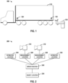
- FIG. 1 illustrates a schematic diagram of a working environment 100 in which embodiments of the present disclosure may be implemented.
- an object 110 such as a container
- lock devices 120 and 122 are still mounted to the container.
- an object location of the object 110 may be determined and then the lock devices 120 and 122 may be removed by a robot system 130 based on the determined lock type.
- sensors such as cameras are adopted to determine object locations of the container objects.
- these cameras are fixed to a crane or another frame at the port and cannot collect overall information for the object. Therefore it is desired to determine the object location in a more effective and convenient manner.
- FIG. 2 illustrates a schematic diagram for determining the object location of the object 110 in according with embodiments of the present disclosure.
- a group of sensors 210 and 212 may be equipped for collecting a group of measurement location for a group of feature marks, respectively.
- the feature mark may comprise any of a lock hole in the object 110 through which the lock device 120 is mounted for securing the object 110. Further, the feature mark may comprise a corner of the object 110.
- the sensor 210 may collect measurement location 220 for one feature mark in the object 110, and the sensor 212 may collect measurement location 222 for another feature mark in the object 110.
- the measure location here may include a position component and an orientation component.
- a group of estimation locations 230 and 232 may be obtained based on the object location and a group of offsets between the group of estimation locations 230 and 232 and the object location, respectively.
- the object location is an unknown value which is to be determined later, and it may be represented by a vector including the position component and the orientation component.
- an error function 240 may be generated and then the object location 250 may be determined based on the error function 240.
- FIG. 3 figure illustrates a flowchart of a method 300 for determining the object location 250 of the object 110 in accordance with embodiments of the present disclosure.
- a group of measurement locations 220 and 222 may be collected from a group of sensors 210 and 212, respectively.
- FIG. 4 for description, which figure illustrates a schematic diagram 400 of a group of feature marks and an object location of an object in accordance with embodiments of the present disclosure.
- FIG. 4 shows a perspective view of the object 110, there are a group of four feature marks 410, 420, 430 and 440 in the object 110.
- the feature mark may comprise any of a lock hole in the object 110 and a corner of the object 110.
- the lock hole and corner are typical features that may be identified from the object based on techniques such as image recognition, machine learning and the like. Accordingly, these embodiments may provide a solid ground for further steps in determining the measurement locations of the feature mark.
- the sensor 210 may be deployed near the object 110 for collecting measurement location 220 for the feature mark 410.
- the sensor 210 may comprise an image measurement camera such as a 2D image camera for collecting image for the feature mark 410. Based on the image processing technique, the measurement location 220 may be determined from the collected image.
- the sensor 210 may also be implemented by 3D camera devices. Specifically, a laser device in the 3D camera may measure a relative position between the feature mark 410 and the laser device so as to measure location 220 in a more accurate manner.
- the measurement location 220 for the feature mark 410 may be represented by a vector ( p 1; ⁇ 1 ), and the measurement location 222 for the feature mark 420 may be represented by a vector ( p 2 , ⁇ 2 ).
- the measurement location 222 for the feature mark 420 may be represented by a vector ( p i ⁇ i ). It is to be understood that each component in the measurement location may also be in a form of a vector.
- p i may represent the position of the feature mark i and may be represented by ( x i , y i , z i ).
- ⁇ i may represent the orientation of the feature mark i and may be represented by various formats.
- the orientation may also be represented by ( pitch i , rall i , yaw i ).
- pitch i i , rall i , yaw i .
- a reference number 450 indicates a center of the object 110, which center may be taken as the object location 250 of the object 110.
- the object location 250 of the object 110 may be represented by a vector ( p c , ⁇ c ).
- the vector ( p c , ⁇ c ) is unknown and the values in the vector may be determined at a block 340 in FIG. 3 .
- a group of estimation locations 230 and 232 for the group of feature marks 410 and 420 may be obtained based on the object location and a group of offsets between the group of estimation locations 230 and 232 and the object location, respectively.
- a location of the feature mark 410 (called as an estimation location) may be represented by the object location ( p c , ⁇ c ) and an offset between the feature mark 410 and the object location ( p c , ⁇ c ).
- FIG. 5 illustrates a schematic diagram 500 for determining an estimation location of a feature mark in accordance with embodiments of the present disclosure.
- a dimension definition 510 may define various aspects of information about the object. For example, a length, a width, a height may be defined, meanwhile a location of the lock hole may also be defined.
- the offset 520 ( p oi' ⁇ oi ) for the feature mark i may be determined based on the length, the width and the location of the lock hole.
- the estimation locations 530 for the feature mark i may be determined based on the object location 250 and the offset 520. Specifically, the estimation location 530 may be represented as ( p c + p oi , ⁇ c + ⁇ oi ).
- the dimension of the object is fixed and the relative locations between the multiple feature marks and the object location are also constant values.
- the dimension definition may be directly obtained from a specification of the object, it provides an easy way for determining the estimation location.
- the error function 240 may be generated based on the group of measurement locations 220 and 222 and the group of estimation locations 230 and 232.
- the number of the feature marks may vary in different embodiments. For example, the number may be 8, 4 or another integer. The following paragraphs will provide more details about the error function 240 where a group of n measurement locations are collected for a group of n feature marks respectively.
- the error function 240 may also include the above two aspects.
- e p,i represents the position error for the feature mark i
- p i represents the position of the measurement location for the feature mark i
- p c represents the position of the object location of the object 110 (which is unknown here)
- e ⁇ c l feature,i represents the position offset in the format of the lie algebra. Accordingly, ( p c + e ⁇ c l feature,i ) represents the estimation location for the feature mark i .
- Formula 1 shows a difference between the measurement location and the estimation location.
- e ⁇ ,i represents the orientation error for the feature mark i
- ⁇ i represents the orientation of the measurement location for the feature mark i
- ⁇ c represents the orientation of the object location of the object 110 (which is unknown here).
- the error function 240 may be generated based on Formula 5, where the operator "T" represents a transposition operation to the matrix e i .
- ⁇ i 1 n e ⁇ i T e ⁇ i
- a group of measurement precision may be obtained for the group of sensors 210 and 212 respectively.
- measurement precision in the group of measurement precision represents a potential error for a measurement location in the group of measurement locations 220 and 222. It is to be understood that, the measurement locations from the sensors are not always precious results and sometimes there may be potential errors.
- the measurement precision may be represented as a matrix Q i .
- the measurement precision depends on hardware/software configurations of the sensor as well as steps implemented during the measure procedure.
- the measurement precision is considered to update the error function 240, such that the error function 240 may reflect more potential aspects of the errors between the measurement location and estimation location.
- the error function 240 may be updated based on the group of measurement precision.
- the object location may be determined based on the error function 240.
- the object location 250 may be determined based on multiple measurement locations for multiple feature marks in the object 110.
- the object location may be determined in an effective and easy way. Further, the above embodiments may be implemented in an automatic way without manual intervention, therefore performance and accuracy may be greatly increased.
- the object location 250 may be determined by solving the error function 240, such that the determined object location 250 limits the error function 240 within a predefined range.
- the object location is represented by an unknown vector and the error function 240 is a function associated with the unknown vector, and thus the unknown vector may be determined by solving the error function 240 under a certain constrain.
- the object location 250 may be set to a vector that minimizes the error function 240, and thus an optimized object location may be determined in an effective and convenient ways.
- a group of errors for the group of feature marks may be determined based on the group of measurement locations and the object location ( p c , ⁇ c ). Specifically, the determined vector ( p c , ⁇ c ) may be brought into any of Formulas 3 to 4 to check whether an individual result
- may represent a norm operation for the matrix e i .
- the determined ( p c , ⁇ c ) may be considered as "valid.”
- the determined object location may be brought to the error function, so as to check whether the determined object location is reliable enough.
- the error threshold may be determined in advance for representing a reliable standard. In these embodiments, only reliable object location may be output for further control the robot system to remove the lock device.
- the determined ( p c , ⁇ c ) may be considered as "invalid" for the feature mark i .
- the measurement location ( p i , ⁇ i ) for the feature mark i may be discarded and the method 300 may be repeated for a further round of determination.
- four sensors are adopted for collecting measurement locations for four feature marks.
- ( p 1 , ⁇ 1 ), ( p 2 , ⁇ 2 ), ( p 3 , ⁇ 3 , and ( p 4 , ⁇ 4 ) may be used to determine the object location ( p c , ⁇ c ).
- a number threshold (for example, 2 or another integer greater than 2) may be set in advance. If the number of the measurement locations is below the number threshold, then the group of measurement locations may be considered as not enough for the object location determination. Continuing the above example, if the newly determined ( p c , ⁇ c ) leads to unreliable
- the location of the sensor may be adjusted for collecting qualified measurement location.
- the sensor may be moved close to the feature mark with a better angle.
- the sensor may be mounted to a robot system in a first gesture, the robot system may be instructed to move from the first gesture to a second gesture to increase the quality of the measurement location. Then, a further measurement location may be collected from the sensor mounted to the robot system in the second gesture.
- FIG. 6 illustrates a schematic diagram 600 for adjusting a gesture of a robot system for collecting a further measurement location of a feature mark in accordance with embodiments of the present disclosure.
- the robot system may be controlled to move along an arrow 610. Therefore, the sensor 210 may be moved to a location 620 for further collecting. As the sensor is mounted to the robot system, the robot system may be instructed to change its gesture for collecting more reliable measurement location(s).
- the lock device that is mounted to the object 110 for securing the object may be removed by a robot system.
- the robot system may be an individual robot system, alternatively, the robot system may be the robot system on which the sensor is mounted.
- an operation of the robot system may be updated based on the determined object location.
- the robot system may be instructed to remove the lock device based on the updated operation.
- large ships carry thousands of containers at one time, and thus countless twist locks are required for securing these containers together.
- the object locations for the container objects may be determined and then the lock devices may be automatically removed by robot systems during an unloading procedure without any manual intervention. Further, the number of human workers may be significantly decreased and efficiency of the unloading procedure may be greatly increased.
- a lock type of the lock device may be obtained first. Then, an operation point in the operation of the robot system may be determined based on the determined lock type. Further, operation points in an operation path of the robot system may be corrected based on the determined object location, and thus the robot system may reach the corrected operation points and remove the lock device effectively.
- FIG. 7 illustrates a schematic diagram 700 for correcting an operation point for an operation of a robot system in accordance with embodiments of the present disclosure.
- the operation 710 is implemented by the robot system for removing the lock device i .
- An operation point 720 may be extracted from the operation 710, and a corrected location 740 of the operation point 720 may be represented as ( p opi , ⁇ opi ) for removing the lock device i .
- the corrected location 740 may be determined based on Formulas 9 and 10.
- e ⁇ c l opi represents an offset between the object location and the operation point 730 for removing the lock device i
- ⁇ o,opi represents an orientation matrix of the operation point 730 in a coordinate of the object 110, which may be determined based on the dimension of the object and the lock device i .
- the robot system may operate in a manner customized for removing the lock device i with a certain lock type.
- embodiments of the present disclosure may be very efficient especially in a port for unloading containers from ships, and container locations of thousands of containers may be automatically determined. Further, with the determined container locations, lock devices mounted on the containers may be removed without any manual intervention.
- FIG. 8 illustrates a schematic diagram of an apparatus 800 for determining an object location of an object in accordance with embodiments of the present disclosure.
- the apparatus 800 may comprise: a collecting unit 810 configured to collect, from a group of sensors, a group of measurement locations for a group of feature marks in the object, respectively; an obtaining unit 820 configured to obtain a group of estimation locations for the group of feature marks based on the object location and a group of offsets between the group of estimation locations and the object location, respectively; a generating unit 830 configured to generate an error function based on the group of measurement locations and the group of estimation locations; and a determining unit 840 configured to determine the object location based on the error function.
- the obtaining unit 820 further configured to: with respect to a feature mark in the group of feature marks, obtain, based on a dimension definition of the object, an offset in the group of offsets between an estimation location for the feature mark and the object location.
- the apparatus 800 further comprises: a precision unit configured to obtain a group of measurement precision for the group of sensors respectively, measurement precision in the group of measurement precision representing a potential error for a measurement location in the group of measurement locations; and an updating unit configured to update the error function based on the group of measurement precision.
- the object location is unknown and comprises a position component and an orientation component
- the determining unit 840 is further configured to: determine the object location by solving the error function, such that the determined object location limits the error function within a predefined range.
- the apparatus 800 further comprises: a checking unit configured to determine a group of errors for the group of feature marks based on the group of measurement locations and the determined object location; and identify the determined object location as "valid" in response to the determined group of errors being below an error threshold.
- the checking unit is further configured to: in response to an error in the group of errors being above the error threshold, remove a measurement location associated with the error from the group of measure locations; and remove an estimation location associated with the error from the group of estimation locations.
- a sensor in the group of sensors is mounted to a robot system in a first gesture
- the apparatus 800 further comprises: an instructing unit configured to, in response to the number of the measurement locations in the group of measurement locations being below a number threshold, instruct the robot system to move from the first gesture to a second gesture; and collect a further measurement location from the sensor mounted to the robot system in the second gesture.
- a feature mark in the group of feature marks comprises any of: a lock hole in the object through which a lock device is mounted for securing the object; and a corner of the object.
- a lock device is mounted to the object for securing the object
- the apparatus 800 further comprises: an instructing unit configured to update an operation of a robot system for removing the lock device based on the determined object location; and instruct the robot system to remove the lock device based on the updated operation.
- the instructing unit is further configured to: obtain a lock type of the lock device; obtain an operation point in the operation of the robot system based on the determined lock type; and correct the operation point based on the determined object location.
- FIG. 9 illustrates a schematic diagram of a computer system 900 for determining an object location of an object in accordance with embodiments of the present disclosure.
- the computer system 900 may comprise a computer processor 910 coupled to a computer-readable memory unit 920, and the memory unit 920 comprises instructions 922.
- the instructions 922 may implement the method for determining an object location of an object as described in the preceding paragraphs, and details will be omitted hereinafter.
- a computer readable medium for determining an object location of an object has instructions stored thereon, and the instructions, when executed on at least one processor, may cause at least one processor to perform the method for determining an object location of an object as described in the preceding paragraphs, and details will be omitted hereinafter.
- FIG. 10 illustrates a schematic diagram of a system 1000 for determining an object location of an object in accordance with embodiments of the present disclosure.
- the system 1000 comprises: a group of sensors 210 and 212 configured to collect a group of measurement locations for a group of feature marks in an object 110, respectively; a group of robot systems 1020 and 1022 configured to support the group of sensors 210 and 212; and a computer system 1010 configured to determine an object location of the object 110 as described in the preceding paragraphs.
- various embodiments of the present disclosure may be implemented in hardware or special purpose circuits, software, logic or any combination thereof. Some aspects may be implemented in hardware, while other aspects may be implemented in firmware or software which may be executed by a controller, microprocessor or other computing device. While various aspects of embodiments of the present disclosure are illustrated and described as block diagrams, flowcharts, or using some other pictorial representation, it will be appreciated that the blocks, apparatus, systems, techniques or methods described herein may be implemented in, as non-limiting examples, hardware, software, firmware, special purpose circuits or logic, general purpose hardware or controller or other computing devices, or some combination thereof.
- the present disclosure also provides at least one computer program product tangibly stored on a non-transitory computer readable storage medium.
- the computer program product includes computer-executable instructions, such as those included in program modules, being executed in a device on a target real or virtual processor, to carry out the process or method as described above with reference to Fig. 3 .
- program modules include routines, programs, libraries, objects, classes, components, data structures, or the like that perform particular tasks or implement particular abstract data types.
- the functionality of the program modules may be combined or split between program modules as desired in various embodiments.
- Machine-executable instructions for program modules may be executed within a local or distributed device. In a distributed device, program modules may be located in both local and remote storage media.
- Program code for carrying out methods of the present disclosure may be written in any combination of one or more programming languages. These program codes may be provided to a processor or controller of a general purpose computer, special purpose computer, or other programmable data processing apparatus, such that the program codes, when executed by the processor or controller, cause the functions/operations specified in the flowcharts and/or block diagrams to be implemented.
- the program code may execute entirely on a machine, partly on the machine, as a stand-alone software package, partly on the machine and partly on a remote machine or entirely on the remote machine or server.
- the above program code may be embodied on a machine readable medium, which may be any tangible medium that may contain, or store a program for use by or in connection with an instruction execution system, apparatus, or device.
- the machine readable medium may be a machine readable signal medium or a machine readable storage medium.
- a machine readable medium may include but not limited to an electronic, magnetic, optical, electromagnetic, infrared, or semiconductor system, apparatus, or device, or any suitable combination of the foregoing.
- machine readable storage medium More specific examples of the machine readable storage medium would include an electrical connection having one or more wires, a portable computer diskette, a hard disk, a random access memory (RAM), a read-only memory (ROM), an erasable programmable read-only memory (EPROM or Flash memory), an optical fiber, a portable compact disc read-only memory (CD-ROM), an optical storage device, a magnetic storage device, or any suitable combination of the foregoing.
- RAM random access memory
- ROM read-only memory
- EPROM or Flash memory erasable programmable read-only memory
- CD-ROM portable compact disc read-only memory
- magnetic storage device or any suitable combination of the foregoing.
Landscapes
- Engineering & Computer Science (AREA)
- Physics & Mathematics (AREA)
- General Physics & Mathematics (AREA)
- Multimedia (AREA)
- Theoretical Computer Science (AREA)
- Software Systems (AREA)
- Robotics (AREA)
- Mechanical Engineering (AREA)
- Length Measuring Devices With Unspecified Measuring Means (AREA)
- Manipulator (AREA)
Claims (15)
- Procédé (300) permettant de déterminer un emplacement d'objet (250) d'un objet (110), le procédé comprenant les étapes consistant à :collecter (310) respectivement, auprès d'un groupe de capteurs (210, 212), un groupe d'emplacements de mesure (220, 222) pour un groupe de marques caractéristiques sur l'objet (110) ;obtenir (320) un groupe d'emplacements d'estimation (230, 232) pour le groupe de marques caractéristiques (410, 420, 430, 440) sur la base respectivement de l'emplacement d'objet, qui est inconnu, et d'un groupe de décalages entre le groupe d'emplacements d'estimation (230, 232) et l'emplacement d'objet ;générer (330) une fonction d'erreur (240) sur la base du groupe d'emplacements de mesure et du groupe d'emplacements d'estimation (230, 232) ;déterminer (340) l'emplacement d'objet (250) sur la base de la fonction d'erreur (240) ; etmettre à jour une opération (710) d'un système robotisé (130) pour retirer un dispositif de verrouillage (120, 122), qui est monté sur l'objet (110) pour sécuriser l'objet (110), sur la base de l'emplacement d'objet (250) déterminé ; etdonner l'instruction au système robotisé (130) de retirer le dispositif de verrouillage (120, 122) sur la base de l'opération mise à jour.
- Procédé selon la revendication 1, comprenant en outre les étapes consistant à :en ce qui concerne une marque caractéristique dans le groupe de marques caractéristiques (410, 420, 430, 440), obtenir, sur la base d'une définition de dimension (510) de l'objet (110), un décalage (520) dans le groupe de décalages entre un emplacement d'estimation (530) pour la marque caractéristique et l'emplacement d'objet (250) ;
et/ouobtenir respectivement un groupe de précisions de mesure pour le groupe de capteurs (210, 212), une précision de mesure dans le groupe de précisions de mesure représentant une erreur potentielle pour un emplacement de mesure dans le groupe d'emplacements de mesure ; etmettre à jour la fonction d'erreur (240) sur la base du groupe de précisions de mesure. - Procédé selon la revendication 1, dans lequel l'emplacement d'objet comprend une composante de position et une composante d'orientation, et dans lequel la détermination (340) de l'emplacement d'objet (250) sur la base de la fonction d'erreur (240) comprend l'étape consistant à :
déterminer l'emplacement d'objet (250) en résolvant la fonction d'erreur (240), de telle sorte que l'emplacement d'objet (250) déterminé limite la fonction d'erreur (240) dans une plage prédéfinie. - Procédé selon la revendication 1, comprenant en outre les étapes consistant à :déterminer un groupe d'erreurs pour le groupe de marques caractéristiques (410, 420, 430, 440) sur la base du groupe d'emplacements de mesure et de l'emplacement d'objet (250) déterminé ; etidentifier l'emplacement d'objet (250) déterminé comme étant « valide » en réponse au fait que le groupe d'erreurs déterminé est inférieur à un seuil d'erreur, de préférence, le procédé comprenant en outre les étapes consistant à : en réponse au fait qu'une erreur du groupe d'erreurs est supérieure au seuil d'erreur,supprimer du groupe d'emplacements de mesure un emplacement de mesure associé à l'erreur ; etsupprimer du groupe d'emplacements d'estimation un emplacement d'estimation associé à l'erreur,un capteur du groupe de capteurs (210, 212) étant de préférence monté sur un système robotisé (130) dans un premier geste, et de préférence le procédé comprenant en outre les étapes consistant à : en réponse au fait que le nombre d'emplacements de mesure du groupe d'emplacements de mesure est inférieur à un nombre seuil, donner l'instruction au système robotisé (130) de passer du premier geste à un second geste (620) ; etcollecter un autre emplacement de mesure auprès du capteur monté sur le système robotisé (130) dans le second geste (620).
- Procédé selon la revendication 1, dans lequel une marque caractéristique du groupe de marques caractéristiques (410, 420, 430, 440) comprend l'un quelconque des éléments suivants :un trou de verrouillage dans l'objet à travers lequel un dispositif de verrouillage (120, 122) est monté pour fixer l'objet (110) ; etun coin de l'objet (110).
- Procédé selon la revendication 1,
dans lequel la mise à jour de l'opération (710) du système robotisé (130) comprend les étapes consistant à :obtenir un type de verrou du dispositif de verrouillage (120, 122) ;obtenir un point d'opération (720) dans l'opération (710) du système robotisé (130) sur la base du type de verrou déterminé ; etcorriger (740) le point d'opération sur la base de l'emplacement d'objet (250) déterminé. - Appareil (800) permettant de déterminer un emplacement d'objet (250) d'un objet (110), l'appareil (800) comprenant :une unité de collecte (810) configurée pour collecter respectivement, auprès d'un groupe de capteurs (210, 212), un groupe d'emplacements de mesure pour un groupe de marques caractéristiques (410, 420, 430, 440) sur l'objet (110) ;une unité d'obtention (820) configurée pour obtenir un groupe d'emplacements d'estimation (230, 232) pour le groupe de marques caractéristiques (410, 420, 430, 440) sur la base respectivement de l'emplacement d'objet, qui est inconnu, et d'un groupe de décalages entre le groupe d'emplacements d'estimation (230, 232) et l'emplacement d'objet ;une unité de génération (830) configurée pour générer une fonction d'erreur (240) sur la base du groupe d'emplacements de mesure et du groupe d'emplacements d'estimation (230, 232) ;une unité de détermination (840) configurée pour déterminer l'emplacement d'objet (250) sur la base de la fonction d'erreur (240) ; etune unité d'instruction configurée pour :mettre à jour une opération (710) d'un système robotisé (130) pour retirer un dispositif de verrouillage (120, 122), qui est monté sur l'objet (110) pour sécuriser l'objet (110), sur la base de l'emplacement d'objet (250) déterminé ; etdonner l'instruction au système robotisé (130) de retirer le dispositif de verrouillage (120, 122) sur la base de l'opération mise à jour.
- Appareil selon la revendication 7,dans lequel l'unité d'obtention (820) est en outre configurée pour : en ce qui concerne une marque caractéristique dans le groupe de marques caractéristiques (410, 420, 430, 440), obtenir, sur la base d'une définition de dimension (510) de l'objet (110), un décalage (520) dans le groupe de décalages entre un emplacement d'estimation (530) pour la marque caractéristique et l'emplacement d'objet (250),
et/oul'appareil comprenant en outre :une unité de précision configurée pour obtenir respectivement un groupe de précisions de mesure pour le groupe de capteurs (210, 212), une précision de mesure dans le groupe de précisions de mesure représentant une erreur potentielle pour un emplacement de mesure dans le groupe d'emplacements de mesure ; etune unité de mise à jour configurée pour mettre à jour la fonction d'erreur (240) sur la base du groupe de précisions de mesure. - Appareil selon la revendication 7, dans lequel l'emplacement d'objet comprend une composante de position et une composante d'orientation, et dans lequel l'unité de détermination (840) est en outre configurée pour :
déterminer l'emplacement d'objet (250) en résolvant la fonction d'erreur (240), de telle sorte que l'emplacement d'objet (250) déterminé limite la fonction d'erreur (240) dans une plage prédéfinie. - Appareil selon la revendication 7, comprenant en outre : une unité de vérification configurée pour :déterminer un groupe d'erreurs pour le groupe de marques caractéristiques (410, 420, 430, 440) sur la base du groupe d'emplacements de mesure et de l'emplacement d'objet (250) déterminé ; etidentifier l'emplacement d'objet (250) déterminé comme étant « valide » en réponse au fait que le groupe d'erreurs déterminé est inférieur à un seuil d'erreur,l'unité de vérification étant de préférence en outre configurée pour : en réponse au fait qu'une erreur du groupe d'erreurs est supérieure au seuil d'erreur,supprimer du groupe d'emplacements de mesure un emplacement de mesure associé à l'erreur ; etsupprimer du groupe d'emplacements d'estimation un emplacement d'estimation associé à l'erreur,un capteur du groupe de capteurs (210, 212) étant de préférence monté sur un système robotisé (130) dans un premier geste, et l'appareil comprenant de préférence en outre : une unité d'instruction configurée pour, en réponse au fait que le nombre d'emplacements de mesure du groupe d'emplacements de mesure est inférieur à un nombre seuil,donner l'instruction au système robotisé (130) de passer du premier geste à un second geste (620) ; etcollecter un autre emplacement de mesure auprès du capteur monté sur le système robotisé (130) dans le second geste (620).
- Appareil selon la revendication 7, dans lequel une marque caractéristique du groupe de marques caractéristiques (410, 420, 430, 440) comprend l'un quelconque des éléments suivants :un trou de verrouillage dans l'objet à travers lequel un dispositif de verrouillage (120, 122) est monté pour fixer l'objet (110) ; etun coin de l'objet (110).
- Appareil selon la revendication 7,
dans lequel l'unité d'instruction est en outre configurée pour :obtenir un type de verrou du dispositif de verrouillage (120, 122) ;obtenir un point d'opération (720) dans l'opération (710) du système robotisé (130) sur la base du type de verrou déterminé ; etcorriger (740) le point d'opération sur la base de l'emplacement d'objet (250) déterminé. - Système informatique (900) permettant de déterminer un emplacement d'objet (250) d'un objet (110), le système informatique comprenant : un processeur informatique (910) couplé à une unité mémoire lisible par ordinateur (920), l'unité mémoire (920) comprenant des instructions qui, lorsqu'elles sont exécutées par le processeur informatique (910), mettent en œuvre le procédé (300) selon l'une quelconque des revendications 1 à 6.
- Support lisible par ordinateur sur lequel sont stockées des instructions qui, lorsqu'elles sont exécutées sur au moins un processeur (910), amènent l'au moins un processeur (910) à effectuer le procédé (300) selon l'une quelconque des revendications 1 à 6.
- Système (1000) permettant de déterminer un emplacement d'objet (250) d'un objet (110), le système comprenant :un groupe de capteurs (210, 212) configurés pour collecter respectivement un groupe d'emplacements de mesure pour un groupe de marques caractéristiques (410, 420, 430, 440) sur un objet ;un groupe de systèmes robotisés (1020, 1022) configurés pour supporter le groupe de capteurs (210, 212) ; etun système informatique (900) configuré pour déterminer un emplacement d'objet (250) de l'objet (110) selon la revendication 13.
Applications Claiming Priority (1)
| Application Number | Priority Date | Filing Date | Title |
|---|---|---|---|
| PCT/CN2019/101125 WO2021030973A1 (fr) | 2019-08-16 | 2019-08-16 | Procédé et appareil permettant de déterminer l'emplacement d'un objet |
Publications (3)
| Publication Number | Publication Date |
|---|---|
| EP4013701A1 EP4013701A1 (fr) | 2022-06-22 |
| EP4013701A4 EP4013701A4 (fr) | 2023-04-19 |
| EP4013701B1 true EP4013701B1 (fr) | 2024-06-05 |
Family
ID=74660134
Family Applications (1)
| Application Number | Title | Priority Date | Filing Date |
|---|---|---|---|
| EP19942348.4A Active EP4013701B1 (fr) | 2019-08-16 | 2019-08-16 | Procédé et appareil permettant de déterminer l'emplacement d'un objet |
Country Status (4)
| Country | Link |
|---|---|
| US (1) | US12315273B2 (fr) |
| EP (1) | EP4013701B1 (fr) |
| CN (1) | CN114364618B (fr) |
| WO (1) | WO2021030973A1 (fr) |
Families Citing this family (1)
| Publication number | Priority date | Publication date | Assignee | Title |
|---|---|---|---|---|
| KR20250107153A (ko) * | 2022-10-07 | 2025-07-11 | 디피 월드 유에이이 레지온 에프제트이 | 트위스트락 보관 시스템 및 관련 방법 |
Family Cites Families (19)
| Publication number | Priority date | Publication date | Assignee | Title |
|---|---|---|---|---|
| CA2532050C (fr) * | 2003-08-14 | 2010-02-23 | Sensis Corporation | Localisation de cible au moyen d'une antenne repartie tdoa |
| JP4128156B2 (ja) * | 2004-06-03 | 2008-07-30 | 松下電器産業株式会社 | 部品実装方法及び装置 |
| US9177210B2 (en) | 2007-10-30 | 2015-11-03 | Hki Systems And Service Llc | Processing container images and identifiers using optical character recognition and geolocation |
| JP5602392B2 (ja) | 2009-06-25 | 2014-10-08 | キヤノン株式会社 | 情報処理装置、情報処理方法およびプログラム |
| JP5393318B2 (ja) * | 2009-07-28 | 2014-01-22 | キヤノン株式会社 | 位置姿勢計測方法及び装置 |
| US8452527B2 (en) | 2010-10-11 | 2013-05-28 | Containertrac, Inc. | Method of automatic positioning for loading and unloading of container ships in container terminals |
| US9459238B1 (en) | 2011-03-14 | 2016-10-04 | Raytheon Company | Methods and apparatus for using acoustic inspection of containers to image objects |
| SG185151A1 (en) * | 2011-04-15 | 2012-11-29 | Manivannan S O Chellappa | Auto stevedore robotic cell |
| US9437005B2 (en) | 2011-07-08 | 2016-09-06 | Canon Kabushiki Kaisha | Information processing apparatus and information processing method |
| US9981812B2 (en) * | 2014-06-05 | 2018-05-29 | Steve Foldesi | Automated handling of shipping containers and connectors |
| ES2627498T3 (es) | 2014-09-24 | 2017-07-28 | Siemens Aktiengesellschaft | Método para la determinación óptica, automática, de una posición objetivo para un dispositivo de elevación de contenedores |
| JP2018072198A (ja) * | 2016-10-31 | 2018-05-10 | 富士通株式会社 | 位置姿勢推定装置、位置姿勢推定方法、及び位置姿勢推定プログラム |
| CN108460800B (zh) | 2016-12-12 | 2020-10-09 | 交通运输部水运科学研究所 | 集装箱图像定位方法及系统 |
| CN106829246A (zh) | 2017-01-22 | 2017-06-13 | 上海振华重工(集团)股份有限公司 | 一种应用于集卡的集装箱锁销自动拆装系统 |
| CN108491851B (zh) * | 2018-01-29 | 2020-07-31 | 江苏大学 | 一种基于机器视觉的集装箱锁孔快速识别与吊具纠偏方法 |
| CN208883030U (zh) | 2018-09-26 | 2019-05-21 | 上海振华港机(集团)宁波传动机械有限公司 | 一种集装箱锁具自动拆装装置 |
| US11061145B2 (en) * | 2018-11-19 | 2021-07-13 | The Boeing Company | Systems and methods of adjusting position information |
| CN109319317A (zh) | 2018-11-28 | 2019-02-12 | 上海国际港务(集团)股份有限公司尚东集装箱码头分公司 | 一种码头集装箱锁销自动装卸视觉定位系统 |
| CN109878926A (zh) | 2019-04-17 | 2019-06-14 | 上海振华重工(集团)股份有限公司 | 集装箱固定锁钮的定位方法及装置 |
-
2019
- 2019-08-16 EP EP19942348.4A patent/EP4013701B1/fr active Active
- 2019-08-16 US US17/635,969 patent/US12315273B2/en active Active
- 2019-08-16 WO PCT/CN2019/101125 patent/WO2021030973A1/fr not_active Ceased
- 2019-08-16 CN CN201980100223.6A patent/CN114364618B/zh active Active
Also Published As
| Publication number | Publication date |
|---|---|
| US12315273B2 (en) | 2025-05-27 |
| CN114364618B (zh) | 2023-03-14 |
| EP4013701A1 (fr) | 2022-06-22 |
| EP4013701A4 (fr) | 2023-04-19 |
| WO2021030973A1 (fr) | 2021-02-25 |
| CN114364618A (zh) | 2022-04-15 |
| US20220335735A1 (en) | 2022-10-20 |
Similar Documents
| Publication | Publication Date | Title |
|---|---|---|
| US10496762B2 (en) | Model generating device, position and orientation calculating device, and handling robot device | |
| US10044996B2 (en) | Method for projecting virtual data and device enabling this projection | |
| US20150015602A1 (en) | System and method for selective determination of point clouds | |
| EP3159125A1 (fr) | Dispositif de reconnaissance de position de robot mobile utilisant le suivi direct, et son procédé | |
| EP3961578B1 (fr) | Atterrissage autonome basé sur la perception pour aéronef | |
| US20190392225A1 (en) | Facility inspection system and facility inspection method | |
| US12131501B2 (en) | System and method for automated estimation of 3D orientation of a physical asset | |
| CN111192331A (zh) | 一种激光雷达和相机的外参标定方法及装置 | |
| US10740649B2 (en) | Object attitude detection device, control device, and robot system | |
| KR102521280B1 (ko) | Slam 기반 이동로봇의 자연사물을 이용한 로봇의 위치추종 방법 및 장치, 컴퓨터 판독가능 기록 매체 및 컴퓨터 프로그램 | |
| US20130021452A1 (en) | Three-dimensional distance measurement apparatus and method therefor | |
| JP7675557B2 (ja) | 位置測定システム | |
| CN116753945A (zh) | 一种基于多传感器融合的工业巡检机器人的导航方法 | |
| EP4013701B1 (fr) | Procédé et appareil permettant de déterminer l'emplacement d'un objet | |
| WO2020047713A1 (fr) | Procédé et appareil de gestion de système de robot | |
| CN113379011A (zh) | 位姿校正方法、装置、设备和存储介质 | |
| EP4621715A1 (fr) | Système de traitement d'informations, procédé de traitement d'informations et support d'informations | |
| US11783472B2 (en) | Color tone correction system and color tone correction method | |
| US20090123033A1 (en) | System and method for adjusting luminance of a light-emitting device on an image measuring machine | |
| US12067085B2 (en) | Method and apparatus for determining lock type | |
| CN115446503B (zh) | 焊接机器人控制方法、装置、焊接机器人和可读介质 | |
| CN114359376B (zh) | 包裹定位方法、装置、电子设备和存储介质 | |
| CN111694370B (zh) | 一种无人机多阶段定点定向降落的视觉方法及系统 | |
| KR20160058455A (ko) | 로버의 상대 위치 추정 장치 및 방법 | |
| CN113841101B (en) | Method for creating an environment map for use in the autonomous navigation of a mobile robot |
Legal Events
| Date | Code | Title | Description |
|---|---|---|---|
| STAA | Information on the status of an ep patent application or granted ep patent |
Free format text: STATUS: THE INTERNATIONAL PUBLICATION HAS BEEN MADE |
|
| PUAI | Public reference made under article 153(3) epc to a published international application that has entered the european phase |
Free format text: ORIGINAL CODE: 0009012 |
|
| STAA | Information on the status of an ep patent application or granted ep patent |
Free format text: STATUS: REQUEST FOR EXAMINATION WAS MADE |
|
| 17P | Request for examination filed |
Effective date: 20220202 |
|
| AK | Designated contracting states |
Kind code of ref document: A1 Designated state(s): AL AT BE BG CH CY CZ DE DK EE ES FI FR GB GR HR HU IE IS IT LI LT LU LV MC MK MT NL NO PL PT RO RS SE SI SK SM TR |
|
| DAV | Request for validation of the european patent (deleted) | ||
| DAX | Request for extension of the european patent (deleted) | ||
| A4 | Supplementary search report drawn up and despatched |
Effective date: 20230320 |
|
| RIC1 | Information provided on ipc code assigned before grant |
Ipc: G01B 11/26 20060101ALI20230314BHEP Ipc: G01B 11/00 20060101ALI20230314BHEP Ipc: B65D 90/00 20060101AFI20230314BHEP |
|
| REG | Reference to a national code |
Ref country code: DE Free format text: PREVIOUS MAIN CLASS: B65D0090000000 Ref legal event code: R079 Ref document number: 602019053421 Country of ref document: DE Ipc: G01B0011260000 |
|
| GRAP | Despatch of communication of intention to grant a patent |
Free format text: ORIGINAL CODE: EPIDOSNIGR1 |
|
| STAA | Information on the status of an ep patent application or granted ep patent |
Free format text: STATUS: GRANT OF PATENT IS INTENDED |
|
| RIC1 | Information provided on ipc code assigned before grant |
Ipc: G01B 11/26 20060101AFI20240229BHEP |
|
| INTG | Intention to grant announced |
Effective date: 20240315 |
|
| GRAS | Grant fee paid |
Free format text: ORIGINAL CODE: EPIDOSNIGR3 |
|
| GRAA | (expected) grant |
Free format text: ORIGINAL CODE: 0009210 |
|
| STAA | Information on the status of an ep patent application or granted ep patent |
Free format text: STATUS: THE PATENT HAS BEEN GRANTED |
|
| AK | Designated contracting states |
Kind code of ref document: B1 Designated state(s): AL AT BE BG CH CY CZ DE DK EE ES FI FR GB GR HR HU IE IS IT LI LT LU LV MC MK MT NL NO PL PT RO RS SE SI SK SM TR |
|
| REG | Reference to a national code |
Ref country code: CH Ref legal event code: EP |
|
| REG | Reference to a national code |
Ref country code: DE Ref legal event code: R096 Ref document number: 602019053421 Country of ref document: DE |
|
| REG | Reference to a national code |
Ref country code: IE Ref legal event code: FG4D |
|
| REG | Reference to a national code |
Ref country code: LT Ref legal event code: MG9D |
|
| PG25 | Lapsed in a contracting state [announced via postgrant information from national office to epo] |
Ref country code: BG Free format text: LAPSE BECAUSE OF FAILURE TO SUBMIT A TRANSLATION OF THE DESCRIPTION OR TO PAY THE FEE WITHIN THE PRESCRIBED TIME-LIMIT Effective date: 20240605 |
|
| REG | Reference to a national code |
Ref country code: NL Ref legal event code: MP Effective date: 20240605 |
|
| PG25 | Lapsed in a contracting state [announced via postgrant information from national office to epo] |
Ref country code: FI Free format text: LAPSE BECAUSE OF FAILURE TO SUBMIT A TRANSLATION OF THE DESCRIPTION OR TO PAY THE FEE WITHIN THE PRESCRIBED TIME-LIMIT Effective date: 20240605 Ref country code: HR Free format text: LAPSE BECAUSE OF FAILURE TO SUBMIT A TRANSLATION OF THE DESCRIPTION OR TO PAY THE FEE WITHIN THE PRESCRIBED TIME-LIMIT Effective date: 20240605 |
|
| PG25 | Lapsed in a contracting state [announced via postgrant information from national office to epo] |
Ref country code: GR Free format text: LAPSE BECAUSE OF FAILURE TO SUBMIT A TRANSLATION OF THE DESCRIPTION OR TO PAY THE FEE WITHIN THE PRESCRIBED TIME-LIMIT Effective date: 20240906 |
|
| PG25 | Lapsed in a contracting state [announced via postgrant information from national office to epo] |
Ref country code: ES Free format text: LAPSE BECAUSE OF FAILURE TO SUBMIT A TRANSLATION OF THE DESCRIPTION OR TO PAY THE FEE WITHIN THE PRESCRIBED TIME-LIMIT Effective date: 20240605 |
|
| PG25 | Lapsed in a contracting state [announced via postgrant information from national office to epo] |
Ref country code: LV Free format text: LAPSE BECAUSE OF FAILURE TO SUBMIT A TRANSLATION OF THE DESCRIPTION OR TO PAY THE FEE WITHIN THE PRESCRIBED TIME-LIMIT Effective date: 20240605 |
|
| PG25 | Lapsed in a contracting state [announced via postgrant information from national office to epo] |
Ref country code: NO Free format text: LAPSE BECAUSE OF FAILURE TO SUBMIT A TRANSLATION OF THE DESCRIPTION OR TO PAY THE FEE WITHIN THE PRESCRIBED TIME-LIMIT Effective date: 20240905 Ref country code: LV Free format text: LAPSE BECAUSE OF FAILURE TO SUBMIT A TRANSLATION OF THE DESCRIPTION OR TO PAY THE FEE WITHIN THE PRESCRIBED TIME-LIMIT Effective date: 20240605 Ref country code: HR Free format text: LAPSE BECAUSE OF FAILURE TO SUBMIT A TRANSLATION OF THE DESCRIPTION OR TO PAY THE FEE WITHIN THE PRESCRIBED TIME-LIMIT Effective date: 20240605 Ref country code: GR Free format text: LAPSE BECAUSE OF FAILURE TO SUBMIT A TRANSLATION OF THE DESCRIPTION OR TO PAY THE FEE WITHIN THE PRESCRIBED TIME-LIMIT Effective date: 20240906 Ref country code: FI Free format text: LAPSE BECAUSE OF FAILURE TO SUBMIT A TRANSLATION OF THE DESCRIPTION OR TO PAY THE FEE WITHIN THE PRESCRIBED TIME-LIMIT Effective date: 20240605 Ref country code: ES Free format text: LAPSE BECAUSE OF FAILURE TO SUBMIT A TRANSLATION OF THE DESCRIPTION OR TO PAY THE FEE WITHIN THE PRESCRIBED TIME-LIMIT Effective date: 20240605 Ref country code: BG Free format text: LAPSE BECAUSE OF FAILURE TO SUBMIT A TRANSLATION OF THE DESCRIPTION OR TO PAY THE FEE WITHIN THE PRESCRIBED TIME-LIMIT Effective date: 20240605 Ref country code: RS Free format text: LAPSE BECAUSE OF FAILURE TO SUBMIT A TRANSLATION OF THE DESCRIPTION OR TO PAY THE FEE WITHIN THE PRESCRIBED TIME-LIMIT Effective date: 20240905 |
|
| PG25 | Lapsed in a contracting state [announced via postgrant information from national office to epo] |
Ref country code: NL Free format text: LAPSE BECAUSE OF FAILURE TO SUBMIT A TRANSLATION OF THE DESCRIPTION OR TO PAY THE FEE WITHIN THE PRESCRIBED TIME-LIMIT Effective date: 20240605 |
|
| REG | Reference to a national code |
Ref country code: AT Ref legal event code: MK05 Ref document number: 1692748 Country of ref document: AT Kind code of ref document: T Effective date: 20240605 |
|
| PG25 | Lapsed in a contracting state [announced via postgrant information from national office to epo] |
Ref country code: NL Free format text: LAPSE BECAUSE OF FAILURE TO SUBMIT A TRANSLATION OF THE DESCRIPTION OR TO PAY THE FEE WITHIN THE PRESCRIBED TIME-LIMIT Effective date: 20240605 |
|
| PG25 | Lapsed in a contracting state [announced via postgrant information from national office to epo] |
Ref country code: PT Free format text: LAPSE BECAUSE OF FAILURE TO SUBMIT A TRANSLATION OF THE DESCRIPTION OR TO PAY THE FEE WITHIN THE PRESCRIBED TIME-LIMIT Effective date: 20241007 |
|
| PG25 | Lapsed in a contracting state [announced via postgrant information from national office to epo] |
Ref country code: PT Free format text: LAPSE BECAUSE OF FAILURE TO SUBMIT A TRANSLATION OF THE DESCRIPTION OR TO PAY THE FEE WITHIN THE PRESCRIBED TIME-LIMIT Effective date: 20241007 |
|
| PG25 | Lapsed in a contracting state [announced via postgrant information from national office to epo] |
Ref country code: PL Free format text: LAPSE BECAUSE OF FAILURE TO SUBMIT A TRANSLATION OF THE DESCRIPTION OR TO PAY THE FEE WITHIN THE PRESCRIBED TIME-LIMIT Effective date: 20240605 |
|
| PG25 | Lapsed in a contracting state [announced via postgrant information from national office to epo] |
Ref country code: EE Free format text: LAPSE BECAUSE OF FAILURE TO SUBMIT A TRANSLATION OF THE DESCRIPTION OR TO PAY THE FEE WITHIN THE PRESCRIBED TIME-LIMIT Effective date: 20240605 |
|
| PG25 | Lapsed in a contracting state [announced via postgrant information from national office to epo] |
Ref country code: AT Free format text: LAPSE BECAUSE OF FAILURE TO SUBMIT A TRANSLATION OF THE DESCRIPTION OR TO PAY THE FEE WITHIN THE PRESCRIBED TIME-LIMIT Effective date: 20240605 Ref country code: IS Free format text: LAPSE BECAUSE OF FAILURE TO SUBMIT A TRANSLATION OF THE DESCRIPTION OR TO PAY THE FEE WITHIN THE PRESCRIBED TIME-LIMIT Effective date: 20241005 |
|
| PG25 | Lapsed in a contracting state [announced via postgrant information from national office to epo] |
Ref country code: CZ Free format text: LAPSE BECAUSE OF FAILURE TO SUBMIT A TRANSLATION OF THE DESCRIPTION OR TO PAY THE FEE WITHIN THE PRESCRIBED TIME-LIMIT Effective date: 20240605 |
|
| PG25 | Lapsed in a contracting state [announced via postgrant information from national office to epo] |
Ref country code: SK Free format text: LAPSE BECAUSE OF FAILURE TO SUBMIT A TRANSLATION OF THE DESCRIPTION OR TO PAY THE FEE WITHIN THE PRESCRIBED TIME-LIMIT Effective date: 20240605 Ref country code: RO Free format text: LAPSE BECAUSE OF FAILURE TO SUBMIT A TRANSLATION OF THE DESCRIPTION OR TO PAY THE FEE WITHIN THE PRESCRIBED TIME-LIMIT Effective date: 20240605 |
|
| PG25 | Lapsed in a contracting state [announced via postgrant information from national office to epo] |
Ref country code: SM Free format text: LAPSE BECAUSE OF FAILURE TO SUBMIT A TRANSLATION OF THE DESCRIPTION OR TO PAY THE FEE WITHIN THE PRESCRIBED TIME-LIMIT Effective date: 20240605 |
|
| PG25 | Lapsed in a contracting state [announced via postgrant information from national office to epo] |
Ref country code: SM Free format text: LAPSE BECAUSE OF FAILURE TO SUBMIT A TRANSLATION OF THE DESCRIPTION OR TO PAY THE FEE WITHIN THE PRESCRIBED TIME-LIMIT Effective date: 20240605 Ref country code: SK Free format text: LAPSE BECAUSE OF FAILURE TO SUBMIT A TRANSLATION OF THE DESCRIPTION OR TO PAY THE FEE WITHIN THE PRESCRIBED TIME-LIMIT Effective date: 20240605 Ref country code: RO Free format text: LAPSE BECAUSE OF FAILURE TO SUBMIT A TRANSLATION OF THE DESCRIPTION OR TO PAY THE FEE WITHIN THE PRESCRIBED TIME-LIMIT Effective date: 20240605 Ref country code: PL Free format text: LAPSE BECAUSE OF FAILURE TO SUBMIT A TRANSLATION OF THE DESCRIPTION OR TO PAY THE FEE WITHIN THE PRESCRIBED TIME-LIMIT Effective date: 20240605 Ref country code: IS Free format text: LAPSE BECAUSE OF FAILURE TO SUBMIT A TRANSLATION OF THE DESCRIPTION OR TO PAY THE FEE WITHIN THE PRESCRIBED TIME-LIMIT Effective date: 20241005 Ref country code: EE Free format text: LAPSE BECAUSE OF FAILURE TO SUBMIT A TRANSLATION OF THE DESCRIPTION OR TO PAY THE FEE WITHIN THE PRESCRIBED TIME-LIMIT Effective date: 20240605 Ref country code: CZ Free format text: LAPSE BECAUSE OF FAILURE TO SUBMIT A TRANSLATION OF THE DESCRIPTION OR TO PAY THE FEE WITHIN THE PRESCRIBED TIME-LIMIT Effective date: 20240605 Ref country code: AT Free format text: LAPSE BECAUSE OF FAILURE TO SUBMIT A TRANSLATION OF THE DESCRIPTION OR TO PAY THE FEE WITHIN THE PRESCRIBED TIME-LIMIT Effective date: 20240605 |
|
| PG25 | Lapsed in a contracting state [announced via postgrant information from national office to epo] |
Ref country code: IT Free format text: LAPSE BECAUSE OF FAILURE TO SUBMIT A TRANSLATION OF THE DESCRIPTION OR TO PAY THE FEE WITHIN THE PRESCRIBED TIME-LIMIT Effective date: 20240605 |
|
| REG | Reference to a national code |
Ref country code: DE Ref legal event code: R097 Ref document number: 602019053421 Country of ref document: DE |
|
| REG | Reference to a national code |
Ref country code: CH Ref legal event code: PL |
|
| PLBE | No opposition filed within time limit |
Free format text: ORIGINAL CODE: 0009261 |
|
| STAA | Information on the status of an ep patent application or granted ep patent |
Free format text: STATUS: NO OPPOSITION FILED WITHIN TIME LIMIT |
|
| PG25 | Lapsed in a contracting state [announced via postgrant information from national office to epo] |
Ref country code: DK Free format text: LAPSE BECAUSE OF FAILURE TO SUBMIT A TRANSLATION OF THE DESCRIPTION OR TO PAY THE FEE WITHIN THE PRESCRIBED TIME-LIMIT Effective date: 20240605 |
|
| PG25 | Lapsed in a contracting state [announced via postgrant information from national office to epo] |
Ref country code: LU Free format text: LAPSE BECAUSE OF NON-PAYMENT OF DUE FEES Effective date: 20240816 |
|
| PG25 | Lapsed in a contracting state [announced via postgrant information from national office to epo] |
Ref country code: CH Free format text: LAPSE BECAUSE OF NON-PAYMENT OF DUE FEES Effective date: 20240831 Ref country code: MC Free format text: LAPSE BECAUSE OF FAILURE TO SUBMIT A TRANSLATION OF THE DESCRIPTION OR TO PAY THE FEE WITHIN THE PRESCRIBED TIME-LIMIT Effective date: 20240605 |
|
| 26N | No opposition filed |
Effective date: 20250306 |
|
| GBPC | Gb: european patent ceased through non-payment of renewal fee |
Effective date: 20240905 |
|
| REG | Reference to a national code |
Ref country code: BE Ref legal event code: MM Effective date: 20240831 |
|
| PG25 | Lapsed in a contracting state [announced via postgrant information from national office to epo] |
Ref country code: GB Free format text: LAPSE BECAUSE OF NON-PAYMENT OF DUE FEES Effective date: 20240905 |
|
| PG25 | Lapsed in a contracting state [announced via postgrant information from national office to epo] |
Ref country code: BE Free format text: LAPSE BECAUSE OF NON-PAYMENT OF DUE FEES Effective date: 20240831 |
|
| PG25 | Lapsed in a contracting state [announced via postgrant information from national office to epo] |
Ref country code: FR Free format text: LAPSE BECAUSE OF NON-PAYMENT OF DUE FEES Effective date: 20240831 |
|
| PG25 | Lapsed in a contracting state [announced via postgrant information from national office to epo] |
Ref country code: IE Free format text: LAPSE BECAUSE OF NON-PAYMENT OF DUE FEES Effective date: 20240816 |
|
| PG25 | Lapsed in a contracting state [announced via postgrant information from national office to epo] |
Ref country code: SE Free format text: LAPSE BECAUSE OF FAILURE TO SUBMIT A TRANSLATION OF THE DESCRIPTION OR TO PAY THE FEE WITHIN THE PRESCRIBED TIME-LIMIT Effective date: 20240605 |
|
| PGFP | Annual fee paid to national office [announced via postgrant information from national office to epo] |
Ref country code: DE Payment date: 20250820 Year of fee payment: 7 |
|
| PG25 | Lapsed in a contracting state [announced via postgrant information from national office to epo] |
Ref country code: CY Free format text: LAPSE BECAUSE OF FAILURE TO SUBMIT A TRANSLATION OF THE DESCRIPTION OR TO PAY THE FEE WITHIN THE PRESCRIBED TIME-LIMIT; INVALID AB INITIO Effective date: 20190816 |
|
| PG25 | Lapsed in a contracting state [announced via postgrant information from national office to epo] |
Ref country code: HU Free format text: LAPSE BECAUSE OF FAILURE TO SUBMIT A TRANSLATION OF THE DESCRIPTION OR TO PAY THE FEE WITHIN THE PRESCRIBED TIME-LIMIT; INVALID AB INITIO Effective date: 20190816 |