EP4013970B1 - Pince de module solaire à verrouillage par torsion - Google Patents
Pince de module solaire à verrouillage par torsion Download PDFInfo
- Publication number
- EP4013970B1 EP4013970B1 EP20893136.0A EP20893136A EP4013970B1 EP 4013970 B1 EP4013970 B1 EP 4013970B1 EP 20893136 A EP20893136 A EP 20893136A EP 4013970 B1 EP4013970 B1 EP 4013970B1
- Authority
- EP
- European Patent Office
- Prior art keywords
- nut
- clamp
- threaded
- planar member
- rail
- Prior art date
- Legal status (The legal status is an assumption and is not a legal conclusion. Google has not performed a legal analysis and makes no representation as to the accuracy of the status listed.)
- Active
Links
Images








Classifications
-
- H—ELECTRICITY
- H02—GENERATION; CONVERSION OR DISTRIBUTION OF ELECTRIC POWER
- H02S—GENERATION OF ELECTRIC POWER BY CONVERSION OF INFRARED RADIATION, VISIBLE LIGHT OR ULTRAVIOLET LIGHT, e.g. USING PHOTOVOLTAIC [PV] MODULES
- H02S30/00—Structural details of PV modules other than those related to light conversion
-
- F—MECHANICAL ENGINEERING; LIGHTING; HEATING; WEAPONS; BLASTING
- F16—ENGINEERING ELEMENTS AND UNITS; GENERAL MEASURES FOR PRODUCING AND MAINTAINING EFFECTIVE FUNCTIONING OF MACHINES OR INSTALLATIONS; THERMAL INSULATION IN GENERAL
- F16B—DEVICES FOR FASTENING OR SECURING CONSTRUCTIONAL ELEMENTS OR MACHINE PARTS TOGETHER, e.g. NAILS, BOLTS, CIRCLIPS, CLAMPS, CLIPS OR WEDGES; JOINTS OR JOINTING
- F16B37/00—Nuts or like thread-engaging members
- F16B37/04—Devices for fastening nuts to surfaces, e.g. sheets, plates
- F16B37/045—Devices for fastening nuts to surfaces, e.g. sheets, plates specially adapted for fastening in channels, e.g. sliding bolts, channel nuts
-
- F—MECHANICAL ENGINEERING; LIGHTING; HEATING; WEAPONS; BLASTING
- F16—ENGINEERING ELEMENTS AND UNITS; GENERAL MEASURES FOR PRODUCING AND MAINTAINING EFFECTIVE FUNCTIONING OF MACHINES OR INSTALLATIONS; THERMAL INSULATION IN GENERAL
- F16B—DEVICES FOR FASTENING OR SECURING CONSTRUCTIONAL ELEMENTS OR MACHINE PARTS TOGETHER, e.g. NAILS, BOLTS, CIRCLIPS, CLAMPS, CLIPS OR WEDGES; JOINTS OR JOINTING
- F16B5/00—Joining sheets or plates, e.g. panels, to one another or to strips or bars parallel to them
- F16B5/0004—Joining sheets, plates or panels in abutting relationship
- F16B5/0056—Joining sheets, plates or panels in abutting relationship by moving the sheets, plates or panels or the interlocking key perpendicular to the main plane
- F16B5/0068—Joining sheets, plates or panels in abutting relationship by moving the sheets, plates or panels or the interlocking key perpendicular to the main plane and using I-shaped clamps with flanges moving towards each other
-
- F—MECHANICAL ENGINEERING; LIGHTING; HEATING; WEAPONS; BLASTING
- F24—HEATING; RANGES; VENTILATING
- F24S—SOLAR HEAT COLLECTORS; SOLAR HEAT SYSTEMS
- F24S25/00—Arrangement of stationary mountings or supports for solar heat collector modules
- F24S25/60—Fixation means, e.g. fasteners, specially adapted for supporting solar heat collector modules
- F24S25/63—Fixation means, e.g. fasteners, specially adapted for supporting solar heat collector modules for fixing modules or their peripheral frames to supporting elements
- F24S25/634—Clamps; Clips
- F24S25/636—Clamps; Clips clamping by screw-threaded elements
-
- H—ELECTRICITY
- H01—ELECTRIC ELEMENTS
- H01R—ELECTRICALLY-CONDUCTIVE CONNECTIONS; STRUCTURAL ASSOCIATIONS OF A PLURALITY OF MUTUALLY-INSULATED ELECTRICAL CONNECTING ELEMENTS; COUPLING DEVICES; CURRENT COLLECTORS
- H01R4/00—Electrically-conductive connections between two or more conductive members in direct contact, i.e. touching one another; Means for effecting or maintaining such contact; Electrically-conductive connections having two or more spaced connecting locations for conductors and using contact members penetrating insulation
- H01R4/28—Clamped connections, spring connections
- H01R4/38—Clamped connections, spring connections utilising a clamping member acted on by screw or nut
- H01R4/44—Clamping areas on both sides of screw
-
- F—MECHANICAL ENGINEERING; LIGHTING; HEATING; WEAPONS; BLASTING
- F16—ENGINEERING ELEMENTS AND UNITS; GENERAL MEASURES FOR PRODUCING AND MAINTAINING EFFECTIVE FUNCTIONING OF MACHINES OR INSTALLATIONS; THERMAL INSULATION IN GENERAL
- F16B—DEVICES FOR FASTENING OR SECURING CONSTRUCTIONAL ELEMENTS OR MACHINE PARTS TOGETHER, e.g. NAILS, BOLTS, CIRCLIPS, CLAMPS, CLIPS OR WEDGES; JOINTS OR JOINTING
- F16B2/00—Friction-grip releasable fastenings
- F16B2/02—Clamps, i.e. with gripping action effected by positive means other than the inherent resistance to deformation of the material of the fastening
- F16B2/06—Clamps, i.e. with gripping action effected by positive means other than the inherent resistance to deformation of the material of the fastening external, i.e. with contracting action
- F16B2/12—Clamps, i.e. with gripping action effected by positive means other than the inherent resistance to deformation of the material of the fastening external, i.e. with contracting action using sliding jaws
-
- F—MECHANICAL ENGINEERING; LIGHTING; HEATING; WEAPONS; BLASTING
- F16—ENGINEERING ELEMENTS AND UNITS; GENERAL MEASURES FOR PRODUCING AND MAINTAINING EFFECTIVE FUNCTIONING OF MACHINES OR INSTALLATIONS; THERMAL INSULATION IN GENERAL
- F16B—DEVICES FOR FASTENING OR SECURING CONSTRUCTIONAL ELEMENTS OR MACHINE PARTS TOGETHER, e.g. NAILS, BOLTS, CIRCLIPS, CLAMPS, CLIPS OR WEDGES; JOINTS OR JOINTING
- F16B37/00—Nuts or like thread-engaging members
- F16B37/04—Devices for fastening nuts to surfaces, e.g. sheets, plates
- F16B37/045—Devices for fastening nuts to surfaces, e.g. sheets, plates specially adapted for fastening in channels, e.g. sliding bolts, channel nuts
- F16B37/046—Devices for fastening nuts to surfaces, e.g. sheets, plates specially adapted for fastening in channels, e.g. sliding bolts, channel nuts with resilient means for urging the nut inside the channel
-
- F—MECHANICAL ENGINEERING; LIGHTING; HEATING; WEAPONS; BLASTING
- F16—ENGINEERING ELEMENTS AND UNITS; GENERAL MEASURES FOR PRODUCING AND MAINTAINING EFFECTIVE FUNCTIONING OF MACHINES OR INSTALLATIONS; THERMAL INSULATION IN GENERAL
- F16B—DEVICES FOR FASTENING OR SECURING CONSTRUCTIONAL ELEMENTS OR MACHINE PARTS TOGETHER, e.g. NAILS, BOLTS, CIRCLIPS, CLAMPS, CLIPS OR WEDGES; JOINTS OR JOINTING
- F16B5/00—Joining sheets or plates, e.g. panels, to one another or to strips or bars parallel to them
- F16B5/06—Joining sheets or plates, e.g. panels, to one another or to strips or bars parallel to them by means of clamps or clips
- F16B5/0607—Joining sheets or plates, e.g. panels, to one another or to strips or bars parallel to them by means of clamps or clips joining sheets or plates to each other
- F16B5/0614—Joining sheets or plates, e.g. panels, to one another or to strips or bars parallel to them by means of clamps or clips joining sheets or plates to each other in angled relationship
-
- F—MECHANICAL ENGINEERING; LIGHTING; HEATING; WEAPONS; BLASTING
- F24—HEATING; RANGES; VENTILATING
- F24S—SOLAR HEAT COLLECTORS; SOLAR HEAT SYSTEMS
- F24S25/00—Arrangement of stationary mountings or supports for solar heat collector modules
- F24S25/60—Fixation means, e.g. fasteners, specially adapted for supporting solar heat collector modules
- F24S2025/6006—Fixation means, e.g. fasteners, specially adapted for supporting solar heat collector modules by using threaded elements, e.g. stud bolts
-
- F—MECHANICAL ENGINEERING; LIGHTING; HEATING; WEAPONS; BLASTING
- F24—HEATING; RANGES; VENTILATING
- F24S—SOLAR HEAT COLLECTORS; SOLAR HEAT SYSTEMS
- F24S25/00—Arrangement of stationary mountings or supports for solar heat collector modules
- F24S25/60—Fixation means, e.g. fasteners, specially adapted for supporting solar heat collector modules
-
- H—ELECTRICITY
- H01—ELECTRIC ELEMENTS
- H01R—ELECTRICALLY-CONDUCTIVE CONNECTIONS; STRUCTURAL ASSOCIATIONS OF A PLURALITY OF MUTUALLY-INSULATED ELECTRICAL CONNECTING ELEMENTS; COUPLING DEVICES; CURRENT COLLECTORS
- H01R4/00—Electrically-conductive connections between two or more conductive members in direct contact, i.e. touching one another; Means for effecting or maintaining such contact; Electrically-conductive connections having two or more spaced connecting locations for conductors and using contact members penetrating insulation
- H01R4/58—Electrically-conductive connections between two or more conductive members in direct contact, i.e. touching one another; Means for effecting or maintaining such contact; Electrically-conductive connections having two or more spaced connecting locations for conductors and using contact members penetrating insulation characterised by the form or material of the contacting members
- H01R4/64—Connections between or with conductive parts having primarily a non-electric function, e.g. frame, casing, rail
-
- Y—GENERAL TAGGING OF NEW TECHNOLOGICAL DEVELOPMENTS; GENERAL TAGGING OF CROSS-SECTIONAL TECHNOLOGIES SPANNING OVER SEVERAL SECTIONS OF THE IPC; TECHNICAL SUBJECTS COVERED BY FORMER USPC CROSS-REFERENCE ART COLLECTIONS [XRACs] AND DIGESTS
- Y02—TECHNOLOGIES OR APPLICATIONS FOR MITIGATION OR ADAPTATION AGAINST CLIMATE CHANGE
- Y02E—REDUCTION OF GREENHOUSE GAS [GHG] EMISSIONS, RELATED TO ENERGY GENERATION, TRANSMISSION OR DISTRIBUTION
- Y02E10/00—Energy generation through renewable energy sources
- Y02E10/40—Solar thermal energy, e.g. solar towers
- Y02E10/47—Mountings or tracking
-
- Y—GENERAL TAGGING OF NEW TECHNOLOGICAL DEVELOPMENTS; GENERAL TAGGING OF CROSS-SECTIONAL TECHNOLOGIES SPANNING OVER SEVERAL SECTIONS OF THE IPC; TECHNICAL SUBJECTS COVERED BY FORMER USPC CROSS-REFERENCE ART COLLECTIONS [XRACs] AND DIGESTS
- Y02—TECHNOLOGIES OR APPLICATIONS FOR MITIGATION OR ADAPTATION AGAINST CLIMATE CHANGE
- Y02E—REDUCTION OF GREENHOUSE GAS [GHG] EMISSIONS, RELATED TO ENERGY GENERATION, TRANSMISSION OR DISTRIBUTION
- Y02E10/00—Energy generation through renewable energy sources
- Y02E10/50—Photovoltaic [PV] energy
Definitions
- FIGs. 1-6 are not encompassed by the wording of the claims but are considered as useful for understanding the invention.
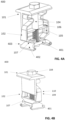
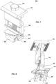
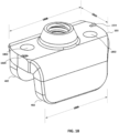
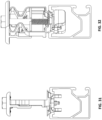
- FIG. 1A depicts an isometric view of the Clamp 100.
- the Clamp 100 is an assembly of a Top Clamp 101, a Spring 102, a T-nut 103, and a fastener 104.
- the Clamp 100 is oriented in the X, Y, and Z cartesian coordinate planes 150.
- the fastener 104 extends through one or more apertures in the Top Clamp 101, an aperture in Spring 102, and threadably engages with T-nut 103; thereby securing all components together.
- Spring 102 has Ribs 105 that pass-through Rib Apertures 106 in the Top Clamp 101.
- Ribs 105 and Rib Apertures 106 may not interfere in the Z direction so as to allow the Top Clamp 101 to compress the Spring 102 and move in the negative Z direction toward the T-nut 103 while the Spring 102 remains in substantially the same position along the Z axis.
- Spring 102 may have an Angled Protrusion 107.
- the Angled Protrusion 107 may be symmetric along the central Y-plane of the Spring 102, or it may be asymmetric.
- the Angled Protrusion 107 may have a flat angular surface as shown, or a curved surface.
- Top Clamp 101, fastener 104, and T-nut 103 may be constructed of an aluminum alloy, stainless steel alloy, carbon steel alloy, or another material with suitable strength properties.
- Spring 102 may be constructed using a polymer, with ultraviolet (UV) resistance and fire resistant properties.
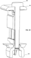
- FIG. 1B depicts a backside isometric view of Clamp 100.
- the Top Clamp 101 extends down in the negative Z direction and is outside of the Spring 102.
- Spring 102 may have one or more Spring Flanges 108 that engage with the T-nut 103 such that when the Spring 102 is rotated about the main axis of the fastener 104, the T-nut 103 rotates substantially the same amount.
- one Spring Flange 108 is shown to protrude down and rests substantially coincident with a side of the T-nut.
- T-nut 103 may have one or more T-nut Flanges 109 that protrude upward at a determined angle.
- the T-nut Flanges 109 may be similarly shaped and angled on the opposing edges of the T-nut 103.
- the T-nut 103 may have one of more Stop Flanges 110 that protrude upward in the positive Z direction.
- the T-nut 103 may have one or more ridges along the top surface near the T-nut Flanges 109 that can pierce a coating on a Rail 200, such as anodization or paint, such that the T-nut 103 electrically bonds with the Rail 200.
- FIG. 1C depicts an underside isometric view of Clamp 100.
- the T-nut has a Cone Embossment 111 formed into the T-nut 103 that provides additional threads in the T-nut 103 for the fastener 104 to threadably engage.
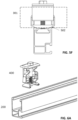
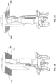
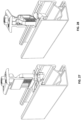
- FIG. 2A depicts an isometric view of the Clamp 100 positioned over a representative section of Rail 200.
- the Clamp 100 is oriented with the long side of T-nut 103 substantially parallel with the length of the Rail 200.
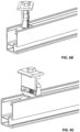
- FIG. 2B depicts a second step of the installation of the Clamp 100 into the Rail 200.
- the Clamp 100 has been partially inserted into the Rail Channel 201.
- the Clamp 100 has not been rotated around the primary axis of the fastener 104.
- the T-nut is positioned below the Rail Prongs 202 of the Rail 200.
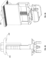
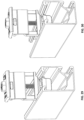
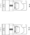
- FIG. 2C depicts a third step of the installation of Clamp 100 into the Rail 200.
- the Clamp 100 is rotated substantially around the primary Z axis of the fastener 104.
- the T-nut rotates below the Rail Prongs 202, and the Angled Protrusion 107 engages with the top edges of the Rail 200, as shown in position 203.
- the Spring 102 compresses the Top Clamp 101 upward, thereby forcing up the T-nut 103 to engage with the Rail Prongs 202.
Landscapes
- Engineering & Computer Science (AREA)
- General Engineering & Computer Science (AREA)
- Mechanical Engineering (AREA)
- Physics & Mathematics (AREA)
- Life Sciences & Earth Sciences (AREA)
- Sustainable Development (AREA)
- Sustainable Energy (AREA)
- Thermal Sciences (AREA)
- Chemical & Material Sciences (AREA)
- Combustion & Propulsion (AREA)
- Clamps And Clips (AREA)
Claims (19)
- Une pince (100) de verrouillage par torsion pour fixer un module solaire à un rail, comprenant :une attache (104) filetée ;une pince (101) de sommet ayant :un premier élément plan ;une première ouverture dans le premier élément plan, la première ouverture étant destinée à accepter l'attache filetée dans une configuration assemblée ; etun deuxième élément plan orthogonal au premier élément plan et assemblé au premier élément plan au voisinage de la première ouverture ;un ressort (102) ayant :une deuxième ouverture pour accepter l'attache filetée dans la configuration assemblée ; etune première surface plane configurée pour coopérer avec une deuxième surface plane sur le rail dans une configuration verrouillée ;une noix (103) en t taraudée pour engrener avec l'attache filetée mettant le ressort en compression entre la pince de sommet et la noix en t taraudée dans la configuration assemblée etun collier (1102) de connexion ayant une découpe et une pluralité de points de contacts exhaussés, dans lequel la découpe permet à l'attache filetée de passer à travers dans la configuration assemblée.
- La pince (100) de verrouillage par torsion de la revendication 1, dans lequel l'attache (104) filetée comprend en outre des anneaux exhaussés de contact électrique avec la pince de sommet.
- La pince (100) de verrouillage suivant la revendication 1 ou 2, dans lequel le ressort (102) comprend en outre au moins deux déclics de noix, les au moins deux déclics de noix coopérant avec au moins deux ouvertures de décalage dans la noix (103) en t taraudée pour retenir la noix en t taraudée lorsque l'attache (104) filetée et la noix en t taraudée sont déconnectées.
- La pince (100) de verrouillage de l'une quelconque des revendications précédentes, dans lequel le ressort (102) comprend en outre une bride voisine d'au moins un déclic de noix, la bride ayant une première dimension plus étroite que l'ouverture de sommet d'une largeur de forme du rail et une deuxième dimension plus large que l'ouverture de sommet de la largeur de fente du rail.
- La pince (100) de verrouillage de l'une quelconque des revendications précédentes, dans lequel la première surface plane de la pince à verrouillage par torsion fait un angle pour coopérer avec une deuxième surface plane faisant un angle sur le rail dans la configuration verrouillée.
- La pince (100) de verrouillage de l'une quelconque des revendications précédentes, comprenant en outre au moins une broche de liaison en acier inoxydable sur le premier élément plan de la pince (101) de sommet.
- La pince (100) de verrouillage de l'une quelconque des revendications précédentes, dans lequel la pluralité de points de contacts exhaussés sont configurés pour un contact électrique avec la pince (101) de sommet et le module solaire.
- La pince (100) de verrouillage de la revendication 7, dans lequel des lettres sur le collier (1102) de connexion identifient une face qui fait face à un panneau d'extrémité.
- La pince (100) de verrouillage de la revendication 7 ou 8, dans lequel le collier (1102) de liaison comprend en outre une bride, qui passe dans une ouverture de la pince (101) de sommet dans la configuration assemblée.
- La pince (100) de verrouillage de la revendication 1, dans lequel le ressort (102) comprend au moins une nervure et la pince (101) de sommet comprend au moins une ouverture de nervure, la nervure et l'ouverture de nervure coopérant pour contraindre une rotation séparée du ressort et de la pince de sommet autour d'un axe de l'attache (104) filetée.
- La pince (100) de verrouillage de la revendication 1, dans lequel la pince (101) de sommet a une encoche latérale à mi-course vers le bas du deuxième élément plan, l'encoche latérale étant à une distance plus grande qu'une épaisseur d'un collier (1102) de connexion, et/ou la pince de sommet a un troisième élément plan à une extrémité distale du deuxième élément plan, le troisième élément plan s'étendant dans l'attache (104) filetée pour coïncider avec un cadre du module solaire dans la configuration assemblée.
- La pince (100) de verrouillage de l'une quelconque des revendications précédentes, dans lequel la noix (103) en t taraudée est la noix en t taraudée de l'une quelconque des revendications 13 à 19.
- Une noix (103) en t taraudée comprenant :un premier élément plan, le premier élément plan étant d'une manière générale rectangulaire et ayant une première dimension et une deuxième dimension orthogonale à la première dimension, dans lequel la première dimension est plus petite que la deuxième dimension, le premier élément plan ayant :une ouverture taraudée centrale ;au moins un point (1804) de contact exhaussé en décalage pour un contact électrique avec un rail ; etau moins une ouverture (1802) en décalage placée latéralement à l'ouverture centrale ;un deuxième élément plan, sensiblement orthogonal au premier élément plan ; etun troisième élément plan, sensiblement orthogonal au premier élément plan, s'étendant du premier élément plan dans une même direction que le deuxième élément plan, le troisième élément plan étant sensiblement parallèle au deuxième élément plan.
- La noix (103) en t taraudée de la revendication 13, dans lequel l'ouverture centrale taraudée est en forme de cône et s'étend dans une direction opposée au deuxième et au troisième éléments plan.
- La noix (103) en t taraudée de la revendication 13, dans lequel l'ouverture centrale taraudée est en forme de cône et s'étend dans même direction que les deuxième et troisième éléments plans.
- La noix (103) en t taraudée de la revendication 13, 14 ou 15, dans lequel le deuxième élément plan est d'une manière générale rectangulaire, en ayant une troisième dimension dans une même direction que la deuxième dimension du premier élément plan et la troisième dimension est plus petite que la deuxième dimension.
- La noix (103) en t taraudée de l'une quelconque des revendications 13 à 16, dans lequel la première dimension du premier élément plan est plus petite qu'une largeur de fente du rail.
- La noix (103) en t taraudée des revendications 13 à 17, dans lequel la deuxième dimension du premier élément plan est plus grande qu'une largeur de forme du rail.
- La noix (103) en t taraudée des revendications 13 à 18, dans lequel la noix en t taraudée est en un matériau d'une dureté plus grande que le rail.
Priority Applications (1)
| Application Number | Priority Date | Filing Date | Title |
|---|---|---|---|
| EP25170142.1A EP4560151A3 (fr) | 2019-11-25 | 2020-11-25 | Pince de module solaire à verrouillage par torsion |
Applications Claiming Priority (3)
| Application Number | Priority Date | Filing Date | Title |
|---|---|---|---|
| US201962940119P | 2019-11-25 | 2019-11-25 | |
| US17/102,749 US12292075B2 (en) | 2019-11-25 | 2020-11-24 | Twist-lock solar module clamp |
| PCT/US2020/062151 WO2021108492A1 (fr) | 2019-11-25 | 2020-11-25 | Pince de module solaire à verrouillage par torsion |
Related Child Applications (2)
| Application Number | Title | Priority Date | Filing Date |
|---|---|---|---|
| EP25170142.1A Division EP4560151A3 (fr) | 2019-11-25 | 2020-11-25 | Pince de module solaire à verrouillage par torsion |
| EP25170142.1A Division-Into EP4560151A3 (fr) | 2019-11-25 | 2020-11-25 | Pince de module solaire à verrouillage par torsion |
Publications (5)
| Publication Number | Publication Date |
|---|---|
| EP4013970A1 EP4013970A1 (fr) | 2022-06-22 |
| EP4013970A4 EP4013970A4 (fr) | 2023-08-30 |
| EP4013970B1 true EP4013970B1 (fr) | 2025-04-16 |
| EP4013970C0 EP4013970C0 (fr) | 2025-04-16 |
| EP4013970B8 EP4013970B8 (fr) | 2026-03-25 |
Family
ID=75971246
Family Applications (2)
| Application Number | Title | Priority Date | Filing Date |
|---|---|---|---|
| EP20893136.0A Active EP4013970B8 (fr) | 2019-11-25 | 2020-11-25 | Pince de module solaire à verrouillage par torsion |
| EP25170142.1A Pending EP4560151A3 (fr) | 2019-11-25 | 2020-11-25 | Pince de module solaire à verrouillage par torsion |
Family Applications After (1)
| Application Number | Title | Priority Date | Filing Date |
|---|---|---|---|
| EP25170142.1A Pending EP4560151A3 (fr) | 2019-11-25 | 2020-11-25 | Pince de module solaire à verrouillage par torsion |
Country Status (4)
| Country | Link |
|---|---|
| US (2) | US12292075B2 (fr) |
| EP (2) | EP4013970B8 (fr) |
| MX (1) | MX2022004556A (fr) |
| WO (1) | WO2021108492A1 (fr) |
Families Citing this family (16)
| Publication number | Priority date | Publication date | Assignee | Title |
|---|---|---|---|---|
| US11815292B2 (en) * | 2012-02-08 | 2023-11-14 | Preformed Line Products Co. | Solar panel clamp |
| US10594250B2 (en) | 2015-08-03 | 2020-03-17 | Unirac Inc. | Hybrid solar panel mounting assembly |
| US11384780B2 (en) * | 2017-12-13 | 2022-07-12 | Tamarack Solar Products, Inc. | Solar panel mounting configuration |
| US11891818B2 (en) | 2019-05-10 | 2024-02-06 | Verco Decking, Inc. | Decking anchor, decking system utilizing the decking anchor, and method of installing the decking anchor |
| US11848636B2 (en) | 2019-06-04 | 2023-12-19 | Pegasus Solar, Inc. | Skip rail system |
| US12292075B2 (en) | 2019-11-25 | 2025-05-06 | Pegasus Solar Inc | Twist-lock solar module clamp |
| US11377840B2 (en) | 2019-11-26 | 2022-07-05 | Pegasus Solar Inc. | One-piece bonding splice for rails |
| US11519185B2 (en) * | 2019-12-27 | 2022-12-06 | Verco Decking, Inc. | Decking anchor, decking system utilizing the decking anchor, and method of installing the decking anchor |
| USD1004141S1 (en) | 2020-12-01 | 2023-11-07 | Pegasus Solar, Inc. | Rail |
| US11990862B2 (en) | 2021-02-18 | 2024-05-21 | Pegasus Solar Inc. | Rail accessory mount |
| US12074558B2 (en) * | 2021-03-17 | 2024-08-27 | Unirac, Inc. | Mounting system for mounting solar panel modules |
| FR3131364B1 (fr) * | 2021-12-23 | 2023-12-15 | A Raymond Et Cie | Dispositif d’attache monobloc d’un panneau photovoltaïque |
| US12281750B2 (en) | 2022-01-14 | 2025-04-22 | Pegasus Solar Inc | Grip rail clamp |
| AU2022221474B1 (en) * | 2022-08-25 | 2023-07-27 | Ims Innovations 2022 Limited | Improvements in and relation to slotted framing systems, retrofitable parts and fittings therefor. |
| US12343851B2 (en) | 2022-09-01 | 2025-07-01 | Unirac, Inc. | Universal end clamp |
| EP4481298A1 (fr) * | 2023-06-20 | 2024-12-25 | Renusol Europe GmbH | Pince modulaire pour fixer au moins un module solaire |
Family Cites Families (181)
| Publication number | Priority date | Publication date | Assignee | Title |
|---|---|---|---|---|
| US2394729A (en) | 1944-08-22 | 1946-02-12 | Tinnerman Products Inc | Fastening device |
| US2712917A (en) | 1951-03-06 | 1955-07-12 | Tinnerman Products Inc | Cable clip or the like |
| US3122604A (en) | 1958-11-12 | 1964-02-25 | Steel City Electric Company | Ground clip for electrical outlet and switch boxes |
| US3145753A (en) | 1961-01-24 | 1964-08-25 | Frederick W Rohe | Spring clip and nut assembly |
| US3066900A (en) | 1961-04-13 | 1962-12-04 | Tinnerman Products Inc | Fastening devices |
| US3966342A (en) | 1974-10-25 | 1976-06-29 | Seiki Hanbai Co., Ltd. | Interior structure frame assembly |
| US4159758A (en) | 1977-09-19 | 1979-07-03 | Westinghouse Electric Corp. | Transportation apparatus |
| JPS5929147Y2 (ja) | 1979-02-24 | 1984-08-22 | トヨタ自動車株式会社 | 弾性軸継手 |
| US4285379A (en) * | 1979-09-17 | 1981-08-25 | B-Line Systems, Inc. | Fastener |
| IT8305006U1 (it) | 1983-10-06 | 1985-04-06 | C O M Coop Operai Metallurgici S C R L | Sistema di collegamento fra due barre cave coassiali e di sezione sostanzialmente rettangolare. |
| US4897005A (en) | 1987-04-01 | 1990-01-30 | Buell Industries, Inc. | Gutted U-nut |
| US4729706A (en) | 1987-04-01 | 1988-03-08 | Buell Industries, Inc. | Fastener clip |
| US4907388A (en) | 1988-08-11 | 1990-03-13 | Siahatgar Mohammed T | Modular panel frame assembly system |
| US4950841A (en) | 1989-05-30 | 1990-08-21 | General Electric Company | Thermally efficient splice joint for electrical distribution busway |
| USD353209S (en) | 1989-11-11 | 1994-12-06 | Dallaire Industries Ltd. | Door side rail extrusion |
| US5203135A (en) | 1991-03-05 | 1993-04-20 | Hamilton Industries, Inc. | Connection for hollow structural members |
| US5144780A (en) | 1991-03-25 | 1992-09-08 | Gieling Thomas G | Portable structure |
| DE4243185A1 (de) * | 1992-12-19 | 1994-06-23 | Hilti Ag | Befestigungsvorrichtung |
| US5423646A (en) | 1993-02-24 | 1995-06-13 | Buell Industries, Inc. | U-nut |
| US5596237A (en) | 1994-03-31 | 1997-01-21 | Emerson Electric Co. | Ground wire attachment for a motor end-shield |
| CA2171918C (fr) | 1995-05-26 | 2000-06-06 | Illinois Tool Works Inc. | Ecrou en u |
| US5657604A (en) | 1995-11-27 | 1997-08-19 | Downing Displays, Inc. | Panel connector |
| DE29700737U1 (de) | 1997-01-16 | 1997-02-27 | Halfen GmbH & Co. KG, 40764 Langenfeld | Spannschraube |
| US7077855B2 (en) | 1999-06-25 | 2006-07-18 | Curtis Patrick M | Pressure clamp for relieving a headache |
| US6032939A (en) | 1999-07-19 | 2000-03-07 | Chen; Jenn-Tzong | Clamp device |
| US6568873B1 (en) | 1999-07-20 | 2003-05-27 | Wallace H. Peterson | In-line connector for window spacer frame tubing |
| US20030177706A1 (en) | 2000-01-14 | 2003-09-25 | Ullman Stanley A. | Mounting system for supporting objects |
| US6205719B1 (en) | 2000-04-26 | 2001-03-27 | Royal Roofing Co., Inc. | Easy-to-install roof screen system |
| US7434362B2 (en) | 2001-07-20 | 2008-10-14 | Unirac, Inc. | System for removably and adjustably mounting a device on a surface |
| US6874971B2 (en) | 2003-07-08 | 2005-04-05 | Freeman Capital Company | Connector for tube and connected tubular structure |
| US7406800B2 (en) | 2004-05-18 | 2008-08-05 | Andalay Solar, Inc. | Mounting system for a solar panel |
| DE102005037825B3 (de) | 2005-08-08 | 2007-03-15 | Demag Cranes & Components Gmbh | Anordnung zur axialen Sicherung eines mit einer Nut versehenen Bolzens |
| GB0519716D0 (en) | 2005-09-28 | 2005-11-02 | Rigidal Systems Ltd | Clamp assembly for a standing seam |
| US8092129B2 (en) | 2006-04-21 | 2012-01-10 | Hubbell Incorporated | Bonding washer |
| DE202007006097U1 (de) | 2007-04-27 | 2008-09-04 | Lisi Automotive Rapid | Vorrichtung zur Befestigung von Bauteilen aneinander mit Hilfe einer auf ein Bauteil aufschiebbaren Klemme |
| DE202007008471U1 (de) | 2007-06-13 | 2007-09-27 | Leichtmetallbau Schletter Gmbh | Vorrichtung zum Verbinden einer Profilschiene mit einem anderen Bauteil |
| US20090114269A1 (en) | 2007-11-07 | 2009-05-07 | Anne Elizabeth Fletcher | Quick release mechanism for solar panels |
| US8585000B2 (en) | 2008-05-22 | 2013-11-19 | Mainstream Energy Corporation | Universal end clamp |
| US7878745B2 (en) | 2008-06-16 | 2011-02-01 | Illinois Tool Works Inc. | U-nut fastener and collated strip thereof |
| US7832180B2 (en) | 2008-10-06 | 2010-11-16 | Alcoa Inc. | Joining structure |
| JP4562793B2 (ja) | 2008-12-05 | 2010-10-13 | シャープ株式会社 | 構造物設置架台、及び太陽電池システム |
| US9447988B2 (en) | 2010-01-25 | 2016-09-20 | Rillito Rive Solar, LLC | Roof mount assembly |
| DE102009000786A1 (de) * | 2009-02-11 | 2010-08-19 | Hilti Aktiengesellschaft | Befestigungsvorrichtung zur Anordnung an einer Montageschiene |
| BRPI1007013A2 (pt) | 2009-02-12 | 2016-03-29 | Illinois Tool Works | porca híbrida na forma de u removível, reutilizável e delonga vida útil. |
| US8869470B2 (en) | 2009-03-21 | 2014-10-28 | Carlo John Lanza | Protective covering for roof device |
| FR2944038B1 (fr) | 2009-04-07 | 2012-02-10 | Cofam Energy | Kit de fixation pour panneau solaire sur une charpente. |
| DE202009007526U1 (de) | 2009-05-27 | 2009-08-20 | Schletter Gmbh | Vorrichtung zur Befestigung einer Montageschiene an einem Gewindeschaft |
| ES2393294T3 (es) | 2009-07-01 | 2012-12-20 | Greenonetec Solarindustrie Gmbh | Combinación de colector de cuba y abrazadera de montaje |
| JP5520544B2 (ja) | 2009-08-26 | 2014-06-11 | 株式会社オーティス | 屋根上取付具 |
| JP5469442B2 (ja) | 2009-12-02 | 2014-04-16 | 落合 俊則 | ソーラパネルの屋根上設置設備、及び、ソーラパネルを屋根上に設置する設置方法 |
| US20120325761A1 (en) | 2009-12-02 | 2012-12-27 | Renusol Gmbh | Mounting system for solar panels, and mounting rail and anchoring device therefor |
| US8695290B1 (en) | 2009-12-07 | 2014-04-15 | Ironridge, Inc. | Systems and methods for splicing solar panel racks |
| JP2011127330A (ja) | 2009-12-17 | 2011-06-30 | Mitsubishi Heavy Ind Ltd | 太陽電池パネルの取付金具 |
| US8181926B2 (en) * | 2010-01-22 | 2012-05-22 | Thomas & Betts International, Inc. | Panel clamp |
| US10472828B2 (en) | 2010-01-25 | 2019-11-12 | EcoFasten Solar, LLC | Roof mounting system |
| TWM395145U (en) | 2010-02-10 | 2010-12-21 | De Poan Pneumatic Corp | Corner connection device of frame used for embedding solar panel |
| DE102010027904A1 (de) | 2010-04-19 | 2011-10-20 | Hilti Aktiengesellschaft | Befestigungsvorrichtung für Anbauteile an Montageschienen |
| US9074796B2 (en) | 2010-09-30 | 2015-07-07 | Apollo Precision (Kunming) Yuanhong Limited | Photovoltaic module support clamp assembly |
| US8656658B2 (en) | 2010-10-20 | 2014-02-25 | Miasole | Retainers for attaching photovoltaic modules to mounting structures |
| US9157665B2 (en) | 2011-03-15 | 2015-10-13 | Richard William Erickson | Unitized photovoltaic assembly |
| JP5653824B2 (ja) * | 2011-04-05 | 2015-01-14 | イワタボルト株式会社 | アースボルト |
| US8375661B1 (en) | 2011-04-15 | 2013-02-19 | The Steel Netork, Inc. | Composite metal deck and concrete floor system |
| US8336277B1 (en) | 2011-07-07 | 2012-12-25 | Solon Corporation | Integrated photovoltaic rooftop modules |
| US8387319B1 (en) | 2011-09-02 | 2013-03-05 | Opsun Systems Inc. | Solar panel securing assembly for sheet metal sloping roofs |
| US8919050B2 (en) | 2011-09-15 | 2014-12-30 | SR Systems, LLC | Anti-torsion construction system providing structural integrity and seismic resistance |
| DE102011114976A1 (de) | 2011-10-06 | 2013-04-11 | Juwi R & D Research Development Gmbh & Co. Kg | Photovoltaikgestell, Pfettenbaugruppe und Verbindungsteil |
| US20130121760A1 (en) | 2011-11-15 | 2013-05-16 | Deming Chen | Expandable clamp with interlacing jaw heads |
| US9647157B2 (en) | 2011-12-13 | 2017-05-09 | Solarcity Corporation | Discrete attachment point apparatus and system for photovoltaic arrays |
| WO2013119555A2 (fr) | 2012-02-06 | 2013-08-15 | First Solar, Inc. | Pince de fixation et configuration de pince de fixation pour installation de module photovoltaïque |
| JP2013177778A (ja) | 2012-02-28 | 2013-09-09 | Sus Corp | 太陽光パネル取付装置 |
| US8752338B2 (en) | 2012-05-04 | 2014-06-17 | D Three Enterprises, Llc | Adjustable roof mounting system |
| DE102012009486A1 (de) | 2012-05-09 | 2013-11-14 | K2 Systems Gmbh | Solarmodulhalter |
| DE202012005714U1 (de) | 2012-06-13 | 2013-09-16 | Schletter Gmbh | Halter für eine Profilschiene |
| US20140000680A1 (en) | 2012-06-27 | 2014-01-02 | E I Du Pont De Nemours And Company | Photovoltaic module with integrated back-sheet and process of manufacuture |
| US10186791B2 (en) | 2012-07-05 | 2019-01-22 | Ironridge, Inc. | Assembly for clamping and grounding objects |
| US9689411B2 (en) | 2012-07-05 | 2017-06-27 | Ironridge, Inc. | Assembly for clamping and grounding objects |
| US20140014163A1 (en) | 2012-07-10 | 2014-01-16 | Cooper Technologies Company | Clip fastener for grounding photovoltaic system |
| US9051950B2 (en) | 2012-08-08 | 2015-06-09 | Thomas & Betts International, Inc. | Universal panel clamp |
| CN102790105B (zh) | 2012-08-13 | 2014-08-06 | 友达光电股份有限公司 | 太阳能模块 |
| US9249813B2 (en) | 2012-10-01 | 2016-02-02 | Technifab, Inc. | Clamp |
| US9142700B2 (en) | 2012-10-16 | 2015-09-22 | Ironridge, Inc. | Assembly for supporting and grounding solar panels |
| US9209529B2 (en) | 2012-12-04 | 2015-12-08 | Thomas & Betts International, Llc | Module edge grounding cable clips |
| WO2014100408A1 (fr) | 2012-12-19 | 2014-06-26 | Patco, Llc | Ensemble de montant |
| DE102013100435A1 (de) | 2013-01-16 | 2014-07-17 | Conductix-Wampfler Gmbh | Verbindungselement für eine Schleifleitung, Schleifleitung und Verfahren zur Herstellung einer Schleifleitung |
| US20140220834A1 (en) | 2013-02-04 | 2014-08-07 | Dynoraxx, Inc. | Solar panel grounding system and clip |
| EP2958230B1 (fr) | 2013-02-18 | 2020-04-08 | KYOCERA Corporation | Dispositif de cellules solaires |
| EP2789931B1 (fr) | 2013-04-12 | 2020-08-12 | Renusol Europe GmbH | Dispositif de maintien pour la fixation d'un module de surface sur un support |
| US9121433B1 (en) | 2013-04-14 | 2015-09-01 | Hilton Raymond Bacon | Joining elements for channelled structural members |
| US8935893B2 (en) | 2013-05-31 | 2015-01-20 | Sunmodo Corporation | Direct rooftop mounting apparatus for solar panels |
| USD732698S1 (en) | 2013-06-28 | 2015-06-23 | Qi Meng | Double track mounting rail for solar panels |
| JP6169929B2 (ja) | 2013-09-19 | 2017-07-26 | 株式会社カネカ | 屋根上設置物取付金具、屋根上設置物の取付構造、太陽電池モジュールの取付構造、屋根構造、及び屋根上設置物の取付工法 |
| US20150102194A1 (en) | 2013-10-15 | 2015-04-16 | Sunmodo Corporation | Solar Panel Rooftop Mounting and Grounding Device |
| US9097443B2 (en) | 2013-10-15 | 2015-08-04 | Sunmodo Corporation | Solar panel rooftop mounting and grounding device |
| US9825581B2 (en) | 2013-11-14 | 2017-11-21 | Ecolibrium Solar, Inc. | Modular sloped roof solar mounting system |
| US8938932B1 (en) | 2013-12-13 | 2015-01-27 | Quality Product Llc | Rail-less roof mounting system |
| US9531319B2 (en) | 2013-12-23 | 2016-12-27 | Sunpower Corporation | Clamps for solar systems |
| EP2908014B1 (fr) | 2014-02-13 | 2019-06-12 | HALFEN GmbH | Vis |
| US9473066B2 (en) | 2014-04-01 | 2016-10-18 | Pegasus Solar Inc. | Mounting assemblies for solar panel systems and methods for using the same |
| US9853593B2 (en) | 2014-07-07 | 2017-12-26 | Spice Solar, Inc. | Solar panel mechanical connector and frame |
| US9520703B2 (en) | 2014-07-31 | 2016-12-13 | Power Distribution, Inc. | Electrical busway splice connector |
| US9813013B2 (en) | 2014-08-05 | 2017-11-07 | Sunrun South Llc | Solar panel installation systems and methods |
| US9473064B2 (en) | 2014-09-18 | 2016-10-18 | D Three Enterprises, Llc | End clip for recessed rail |
| US9806668B2 (en) | 2014-09-23 | 2017-10-31 | Solarcity Corporation | Photovoltaic mounting system for tiled roofs |
| CA2907509C (fr) | 2014-10-17 | 2023-04-11 | Manish Nayar | Mecanisme de fixation et ecrou pour dispositif de support de panneau solaire |
| US9660570B2 (en) | 2014-10-20 | 2017-05-23 | Pegasus Solar Inc. | Clamps for securing solar energy panels |
| DE202014009489U1 (de) | 2014-11-26 | 2014-12-12 | Mounting Systems Gmbh | Endhalter und Befestigungssystem zur Montage von Solarmodulen |
| US9755571B2 (en) | 2015-02-25 | 2017-09-05 | Solarcity Corporation | Photovoltaic mounting system with chemical flashing |
| US10340837B2 (en) | 2015-03-11 | 2019-07-02 | Ecolibrium Solar, Inc | Sloped roof solar panel mounting system |
| US10756668B2 (en) | 2015-03-11 | 2020-08-25 | Ecouni, Llc | Universal sloped roof solar panel mounting system |
| US20160285408A1 (en) | 2015-03-25 | 2016-09-29 | Ironridge, Inc. | Clamp for securing and electrically bonding solar panels to a rail support |
| US10240820B2 (en) | 2015-03-25 | 2019-03-26 | Ironridge, Inc. | Clamp for securing and electrically bonding solar panels to a rail support |
| US9407079B1 (en) | 2015-04-16 | 2016-08-02 | Eaton Corporation | Busway systems and related assemblies and methods |
| US9748892B2 (en) * | 2015-07-27 | 2017-08-29 | Solarcity Corporation | Clip-in mounting system for photovoltaic systems |
| US10340838B2 (en) | 2015-08-03 | 2019-07-02 | Unirac Inc. | Hybrid solar panel mounting assembly with a tilted ledge |
| CN105369898B (zh) | 2015-08-25 | 2017-10-13 | 河南奥斯派克科技有限公司 | 基于bim的薄壁槽钢组合房屋 |
| US9819303B2 (en) | 2015-08-31 | 2017-11-14 | Ironridge, Inc. | Apparatus for securing a solar panel rail guide to a support bracket |
| US9837954B2 (en) | 2015-08-31 | 2017-12-05 | Ironridge, Inc. | Electrical bonding splice for solar panel rail guides |
| US10361652B2 (en) | 2015-09-14 | 2019-07-23 | Vivint Solar, Inc. | Solar module mounting |
| US9673752B2 (en) | 2015-11-09 | 2017-06-06 | Solarcity Corporation | Photovoltaic array skirt and mounting hardware |
| WO2017100574A1 (fr) * | 2015-12-09 | 2017-06-15 | Hubbell Incorporated | Collier de fixation |
| US9590406B1 (en) | 2016-01-07 | 2017-03-07 | General Electric Company | Busway joint coupling having a splice plate with a longitudinal rib |
| US9705299B1 (en) | 2016-01-07 | 2017-07-11 | General Electric Company | Electrical busway joint with external vise braces |
| US9882366B2 (en) | 2016-01-07 | 2018-01-30 | General Electric Company | Electrical busway joint with self-adjusting braces |
| US9590405B1 (en) | 2016-01-07 | 2017-03-07 | General Electric Company | Busway joint coupling having an adjustable assembly for joining two busway sections |
| US20170233996A1 (en) | 2016-02-16 | 2017-08-17 | Bull Moose Tube Company | Connectors and methods of fabricating the same |
| US10852038B2 (en) | 2016-04-13 | 2020-12-01 | Elie Rothschild | Bonding jumper clip for solar panels |
| US10097133B2 (en) | 2016-04-14 | 2018-10-09 | Shahriar Shamloo Aliabadi | Racking system for installing solar panels |
| US10320164B2 (en) * | 2016-05-05 | 2019-06-11 | Rxl, Inc. | Grounding clip |
| US20170366131A1 (en) | 2016-06-21 | 2017-12-21 | Rillito River Solar, Llc | Solar panel mounting system, method and apparatus |
| US9813015B1 (en) | 2016-06-29 | 2017-11-07 | Sunpower Corporation | End clamp for mounting solar module to rail |
| MX2019001742A (es) | 2016-08-18 | 2019-08-12 | Bull Moose Tube Company | Conectores de empalme para segmentos estructurales huecos y metodos para hacer los mismos. |
| US11085484B2 (en) | 2016-09-23 | 2021-08-10 | Sunpower Corporation | Water sealing surface attachment |
| US10103688B2 (en) | 2016-09-29 | 2018-10-16 | Sunpower Corporation | Systems and methods for improved installation and grounding of photovoltaic assemblies |
| US9932734B1 (en) | 2016-10-03 | 2018-04-03 | Roger Winter | Deck component with post sleeve and flanges |
| CN108071195A (zh) | 2016-11-16 | 2018-05-25 | 江苏晨科新能源有限公司 | 一种彩钢瓦夹具 |
| US10781587B2 (en) | 2016-12-14 | 2020-09-22 | Solsera, Inc. | Structural attachment sealing system |
| JP6863776B2 (ja) | 2017-03-07 | 2021-04-21 | 積水化学工業株式会社 | 継手構造および建築用構造体 |
| WO2018204137A1 (fr) | 2017-05-01 | 2018-11-08 | Hubbell Incorporated | Bride terminale de liaison universelle |
| US10211773B2 (en) * | 2017-05-24 | 2019-02-19 | Sunmodo Corporation | Height-adjustable solar panel mounting device |
| US20180367090A1 (en) | 2017-06-20 | 2018-12-20 | Watershed Solar LLC | Integrated photovoltaic module mounting system for installation on a sloped surface |
| US9893677B1 (en) | 2017-07-06 | 2018-02-13 | Sunmodo Corporation | Bottom clamp for mounting solar panels to roofs |
| US11251743B2 (en) | 2017-07-25 | 2022-02-15 | Unirac Inc. | Click-on tower and l-foot mount for attaching solar panels to a roof |
| US10451315B2 (en) | 2017-08-08 | 2019-10-22 | Unirac Inc. | Universal end clamp for mounting solar panels on structural rails |
| US11313591B1 (en) * | 2017-09-11 | 2022-04-26 | Moti Atia | Universal clamp apparatus to accommodate solar panel frames with different thicknesses |
| US20190264452A1 (en) | 2017-10-02 | 2019-08-29 | Cully Scott Cangelosi | Roof platform configured for use on an inclined roof |
| US11384780B2 (en) | 2017-12-13 | 2022-07-12 | Tamarack Solar Products, Inc. | Solar panel mounting configuration |
| US10218305B1 (en) | 2018-04-16 | 2019-02-26 | Sunmodo Corporation | End clamp for attaching solar panels to roofs |
| US10992251B2 (en) * | 2018-04-23 | 2021-04-27 | Solar Foundations Usa, Inc. | Integrated bonding mid clamp device, system, and method for solar panel mounting and grounding |
| US11290053B2 (en) | 2019-04-01 | 2022-03-29 | Unirac Inc. | Solar panel mounting apparatus |
| US10749459B1 (en) * | 2019-05-10 | 2020-08-18 | Sunmodo Corporation | Solar panel top clamp assembly for roofs and the like |
| US10847960B1 (en) | 2019-05-16 | 2020-11-24 | Hubbell Incorporated | Multi-directional cable clip |
| US11848636B2 (en) | 2019-06-04 | 2023-12-19 | Pegasus Solar, Inc. | Skip rail system |
| US11588434B2 (en) | 2019-06-18 | 2023-02-21 | Nextracker Llc | Expandable splice for a solar power system |
| US11486434B2 (en) | 2019-07-16 | 2022-11-01 | Pmc Industries, Inc. | Rail mounting apparatus, system and method of securing devices to a structure |
| US20210067083A1 (en) | 2019-08-26 | 2021-03-04 | Pegasus Solar, Inc. | Kit of cross-compatible parts for multiple solar installation methods |
| CN110454997B (zh) | 2019-09-10 | 2024-06-11 | 浙江正泰新能源开发有限公司 | 光伏组件快装固定结构 |
| US10914513B1 (en) * | 2019-09-10 | 2021-02-09 | Whirlpool Corportion | Appliance mounting assembly |
| US12292075B2 (en) | 2019-11-25 | 2025-05-06 | Pegasus Solar Inc | Twist-lock solar module clamp |
| US11377840B2 (en) | 2019-11-26 | 2022-07-05 | Pegasus Solar Inc. | One-piece bonding splice for rails |
| US12143060B2 (en) | 2019-12-11 | 2024-11-12 | Ironridge, Inc. | Electrical bonding splice for solar panel rail guides |
| US11811358B2 (en) | 2020-02-11 | 2023-11-07 | Apa Solar, Llc | Solar module mounting system |
| US11258397B2 (en) * | 2020-02-11 | 2022-02-22 | Ap Alternatives, Llc | Solar module mounting system |
| US11152889B1 (en) | 2020-03-12 | 2021-10-19 | Sunrun Inc. | Mount assemblies with chemical flashings |
| USD1004141S1 (en) | 2020-12-01 | 2023-11-07 | Pegasus Solar, Inc. | Rail |
| US20220190781A1 (en) | 2020-12-11 | 2022-06-16 | Pegasus Solar, Inc. | Row-to-row bonding jumper |
| US11143436B1 (en) | 2020-12-14 | 2021-10-12 | Pegasus Solar, Inc. | Hidden end clamp |
| US11611310B2 (en) | 2021-01-22 | 2023-03-21 | Pegasus Solar Inc. | Hinged solar mount |
| US11990862B2 (en) | 2021-02-18 | 2024-05-21 | Pegasus Solar Inc. | Rail accessory mount |
| US12074558B2 (en) | 2021-03-17 | 2024-08-27 | Unirac, Inc. | Mounting system for mounting solar panel modules |
| US11296648B1 (en) | 2021-05-14 | 2022-04-05 | Sunmodo Corporation | Solar panel racking system and devices for the same |
| US11728760B2 (en) | 2021-06-16 | 2023-08-15 | Tectonicus Constructs, Llc | Pivotable support structure for cross canal solar array |
| US11336222B1 (en) | 2021-10-15 | 2022-05-17 | David G. Garza | Universal clamp assembly |
| WO2023107569A1 (fr) | 2021-12-07 | 2023-06-15 | Pegasus Solar, Inc. | Éclisse de rail à caractéristiques de serrage |
| JP2024546678A (ja) | 2021-12-07 | 2024-12-26 | セルジーン コーポレーション | 神経変性疾患治療のためのカルボン酸含有インダニル化合物 |
| US20230204829A1 (en) | 2021-12-27 | 2023-06-29 | Tdk Taiwan Corp. | Optical element driving mechanism |
| US12281750B2 (en) | 2022-01-14 | 2025-04-22 | Pegasus Solar Inc | Grip rail clamp |
| JP2025527410A (ja) | 2022-08-19 | 2025-08-22 | ペガサス・ソーラー・インコーポレイテッド | 一体型シーラントを備える屋根取り付け具 |
| WO2024097416A1 (fr) | 2022-11-03 | 2024-05-10 | Pegasus Solar, Inc. | Pince de couplage de module |
| WO2024168100A1 (fr) | 2023-02-07 | 2024-08-15 | Pegasus Solar, Inc. | Système de pied inclinable pour réseaux de panneaux solaires |
| US11757400B1 (en) | 2023-03-15 | 2023-09-12 | Sunmodo Corporation | Devices for mounting solar PV panels to roofs and other mounting structures |
| US20250055408A1 (en) | 2023-08-07 | 2025-02-13 | Pegasus Solar, Inc. | Skip mount installation system |
-
2020
- 2020-11-24 US US17/102,749 patent/US12292075B2/en active Active
- 2020-11-25 EP EP20893136.0A patent/EP4013970B8/fr active Active
- 2020-11-25 WO PCT/US2020/062151 patent/WO2021108492A1/fr not_active Ceased
- 2020-11-25 EP EP25170142.1A patent/EP4560151A3/fr active Pending
- 2020-11-25 MX MX2022004556A patent/MX2022004556A/es unknown
-
2025
- 2025-03-18 US US19/083,167 patent/US20250215919A1/en active Pending
Also Published As
| Publication number | Publication date |
|---|---|
| EP4560151A3 (fr) | 2025-08-06 |
| WO2021108492A1 (fr) | 2021-06-03 |
| EP4013970A4 (fr) | 2023-08-30 |
| EP4013970A1 (fr) | 2022-06-22 |
| MX2022004556A (es) | 2022-05-06 |
| EP4013970B8 (fr) | 2026-03-25 |
| US20250215919A1 (en) | 2025-07-03 |
| EP4013970C0 (fr) | 2025-04-16 |
| US12292075B2 (en) | 2025-05-06 |
| US20210156413A1 (en) | 2021-05-27 |
| EP4560151A2 (fr) | 2025-05-28 |
Similar Documents
| Publication | Publication Date | Title |
|---|---|---|
| EP4013970B1 (fr) | Pince de module solaire à verrouillage par torsion | |
| US11990862B2 (en) | Rail accessory mount | |
| US11196187B2 (en) | Universal end clamp for securing a solar panel to a rail support guide | |
| AU2015336012B2 (en) | Clamps for securing solar energy panels | |
| US9595772B2 (en) | Adjustable bonding washer | |
| EP0632530B1 (fr) | Cosse de batterie | |
| EP1703584B1 (fr) | Ensemble de montage d'antenne pour toit d'automobile | |
| EP0606068A1 (fr) | Borne de batterie | |
| US11614118B2 (en) | Clinch fastener | |
| US7054158B2 (en) | Cooling body | |
| JP6869924B2 (ja) | スタッド係止具 | |
| US10752182B2 (en) | Quarter turn clip for connecting a vehicle metal sheet plate and an expanded polypropylene vehicle panel and quarter turn clip and expanded polypropylene vehicle panel assembly | |
| CN1835288A (zh) | 用于金属型材的接地装置 | |
| US12119603B2 (en) | Two-part grounding clamp for cables | |
| WO2016198923A1 (fr) | Système de fixation mécanique pour fixer deux parties de feuille métallique | |
| TWI843765B (zh) | 緊固件與面板總成及其固定方法 | |
| US7146688B2 (en) | Apparatus and method for engaging cables | |
| EP4572022A1 (fr) | Pince pour conducteurs | |
| WO2025030257A1 (fr) | Structure de liaison d'élément de fixation à double verrouillage | |
| US8401358B2 (en) | Attachment part and electronic apparatus | |
| JP2019065982A (ja) | 固定金具 | |
| JPS6252163B2 (fr) | ||
| KR20120089293A (ko) | 조립 부품 및 조립 부품을 생산하는 방법 | |
| JP4132752B2 (ja) | 電線クランプ | |
| CN115552133A (zh) | 用于安装遮盖件的夹具 |
Legal Events
| Date | Code | Title | Description |
|---|---|---|---|
| STAA | Information on the status of an ep patent application or granted ep patent |
Free format text: STATUS: THE INTERNATIONAL PUBLICATION HAS BEEN MADE |
|
| PUAI | Public reference made under article 153(3) epc to a published international application that has entered the european phase |
Free format text: ORIGINAL CODE: 0009012 |
|
| STAA | Information on the status of an ep patent application or granted ep patent |
Free format text: STATUS: REQUEST FOR EXAMINATION WAS MADE |
|
| 17P | Request for examination filed |
Effective date: 20220317 |
|
| AK | Designated contracting states |
Kind code of ref document: A1 Designated state(s): AL AT BE BG CH CY CZ DE DK EE ES FI FR GB GR HR HU IE IS IT LI LT LU LV MC MK MT NL NO PL PT RO RS SE SI SK SM TR |
|
| DAV | Request for validation of the european patent (deleted) | ||
| DAX | Request for extension of the european patent (deleted) | ||
| REG | Reference to a national code |
Ref country code: DE Ref legal event code: R079 Free format text: PREVIOUS MAIN CLASS: F16B0021020000 Ipc: F16B0037040000 Ref document number: 602020049727 Country of ref document: DE |
|
| A4 | Supplementary search report drawn up and despatched |
Effective date: 20230802 |
|
| RIC1 | Information provided on ipc code assigned before grant |
Ipc: F16B 5/06 20060101ALN20230727BHEP Ipc: F16B 2/12 20060101ALN20230727BHEP Ipc: F16B 37/04 20060101AFI20230727BHEP |
|
| GRAP | Despatch of communication of intention to grant a patent |
Free format text: ORIGINAL CODE: EPIDOSNIGR1 |
|
| STAA | Information on the status of an ep patent application or granted ep patent |
Free format text: STATUS: GRANT OF PATENT IS INTENDED |
|
| RIC1 | Information provided on ipc code assigned before grant |
Ipc: F16B 5/06 20060101ALN20241121BHEP Ipc: F16B 2/12 20060101ALN20241121BHEP Ipc: F16B 37/04 20060101AFI20241121BHEP |
|
| RIC1 | Information provided on ipc code assigned before grant |
Ipc: F16B 5/06 20060101ALN20241127BHEP Ipc: F16B 2/12 20060101ALN20241127BHEP Ipc: F16B 37/04 20060101AFI20241127BHEP |
|
| INTG | Intention to grant announced |
Effective date: 20241211 |
|
| GRAS | Grant fee paid |
Free format text: ORIGINAL CODE: EPIDOSNIGR3 |
|
| GRAA | (expected) grant |
Free format text: ORIGINAL CODE: 0009210 |
|
| STAA | Information on the status of an ep patent application or granted ep patent |
Free format text: STATUS: THE PATENT HAS BEEN GRANTED |
|
| AK | Designated contracting states |
Kind code of ref document: B1 Designated state(s): AL AT BE BG CH CY CZ DE DK EE ES FI FR GB GR HR HU IE IS IT LI LT LU LV MC MK MT NL NO PL PT RO RS SE SI SK SM TR |
|
| REG | Reference to a national code |
Ref country code: GB Ref legal event code: FG4D |
|
| REG | Reference to a national code |
Ref country code: CH Ref legal event code: EP Ref country code: DE Ref legal event code: R096 Ref document number: 602020049727 Country of ref document: DE |
|
| REG | Reference to a national code |
Ref country code: IE Ref legal event code: FG4D |
|
| U01 | Request for unitary effect filed |
Effective date: 20250417 |
|
| U07 | Unitary effect registered |
Designated state(s): AT BE BG DE DK EE FI FR IT LT LU LV MT NL PT RO SE SI Effective date: 20250424 |
|
| PG25 | Lapsed in a contracting state [announced via postgrant information from national office to epo] |
Ref country code: ES Free format text: LAPSE BECAUSE OF FAILURE TO SUBMIT A TRANSLATION OF THE DESCRIPTION OR TO PAY THE FEE WITHIN THE PRESCRIBED TIME-LIMIT Effective date: 20250416 |
|
| PG25 | Lapsed in a contracting state [announced via postgrant information from national office to epo] |
Ref country code: NO Free format text: LAPSE BECAUSE OF FAILURE TO SUBMIT A TRANSLATION OF THE DESCRIPTION OR TO PAY THE FEE WITHIN THE PRESCRIBED TIME-LIMIT Effective date: 20250716 Ref country code: GR Free format text: LAPSE BECAUSE OF FAILURE TO SUBMIT A TRANSLATION OF THE DESCRIPTION OR TO PAY THE FEE WITHIN THE PRESCRIBED TIME-LIMIT Effective date: 20250717 |
|
| PG25 | Lapsed in a contracting state [announced via postgrant information from national office to epo] |
Ref country code: PL Free format text: LAPSE BECAUSE OF FAILURE TO SUBMIT A TRANSLATION OF THE DESCRIPTION OR TO PAY THE FEE WITHIN THE PRESCRIBED TIME-LIMIT Effective date: 20250416 |
|
| PG25 | Lapsed in a contracting state [announced via postgrant information from national office to epo] |
Ref country code: HR Free format text: LAPSE BECAUSE OF FAILURE TO SUBMIT A TRANSLATION OF THE DESCRIPTION OR TO PAY THE FEE WITHIN THE PRESCRIBED TIME-LIMIT Effective date: 20250416 |
|
| PG25 | Lapsed in a contracting state [announced via postgrant information from national office to epo] |
Ref country code: RS Free format text: LAPSE BECAUSE OF FAILURE TO SUBMIT A TRANSLATION OF THE DESCRIPTION OR TO PAY THE FEE WITHIN THE PRESCRIBED TIME-LIMIT Effective date: 20250716 |
|
| PG25 | Lapsed in a contracting state [announced via postgrant information from national office to epo] |
Ref country code: IS Free format text: LAPSE BECAUSE OF FAILURE TO SUBMIT A TRANSLATION OF THE DESCRIPTION OR TO PAY THE FEE WITHIN THE PRESCRIBED TIME-LIMIT Effective date: 20250816 |
|
| U20 | Renewal fee for the european patent with unitary effect paid |
Year of fee payment: 6 Effective date: 20251114 |
|
| PG25 | Lapsed in a contracting state [announced via postgrant information from national office to epo] |
Ref country code: SM Free format text: LAPSE BECAUSE OF FAILURE TO SUBMIT A TRANSLATION OF THE DESCRIPTION OR TO PAY THE FEE WITHIN THE PRESCRIBED TIME-LIMIT Effective date: 20250416 |
|
| PG25 | Lapsed in a contracting state [announced via postgrant information from national office to epo] |
Ref country code: CZ Free format text: LAPSE BECAUSE OF FAILURE TO SUBMIT A TRANSLATION OF THE DESCRIPTION OR TO PAY THE FEE WITHIN THE PRESCRIBED TIME-LIMIT Effective date: 20250416 |
|
| PG25 | Lapsed in a contracting state [announced via postgrant information from national office to epo] |
Ref country code: SK Free format text: LAPSE BECAUSE OF FAILURE TO SUBMIT A TRANSLATION OF THE DESCRIPTION OR TO PAY THE FEE WITHIN THE PRESCRIBED TIME-LIMIT Effective date: 20250416 |
|
| GRAT | Correction requested after decision to grant or after decision to maintain patent in amended form |
Free format text: ORIGINAL CODE: EPIDOSNCDEC |
|
| PLBE | No opposition filed within time limit |
Free format text: ORIGINAL CODE: 0009261 |
|
| STAA | Information on the status of an ep patent application or granted ep patent |
Free format text: STATUS: NO OPPOSITION FILED WITHIN TIME LIMIT |
|
| REG | Reference to a national code |
Ref country code: CH Ref legal event code: L10 Free format text: ST27 STATUS EVENT CODE: U-0-0-L10-L00 (AS PROVIDED BY THE NATIONAL OFFICE) Effective date: 20260225 Ref country code: CH Ref legal event code: Q17 Free format text: ST27 STATUS EVENT CODE: U-0-0-Q10-Q17 (AS PROVIDED BY THE NATIONAL OFFICE) Effective date: 20260225 |
|
| 26N | No opposition filed |
Effective date: 20260119 |
|
| U1H | Name or address of the proprietor changed after the registration of the unitary effect |
Owner name: PEGASUS SOLAR INC; US |