EP4014726A1 - Schmiervorrichtung zum schmieren von käselaiben - Google Patents
Schmiervorrichtung zum schmieren von käselaiben Download PDFInfo
- Publication number
- EP4014726A1 EP4014726A1 EP21213388.8A EP21213388A EP4014726A1 EP 4014726 A1 EP4014726 A1 EP 4014726A1 EP 21213388 A EP21213388 A EP 21213388A EP 4014726 A1 EP4014726 A1 EP 4014726A1
- Authority
- EP
- European Patent Office
- Prior art keywords
- brush
- rocker
- cheese
- lubricating
- axis
- Prior art date
- Legal status (The legal status is an assumption and is not a legal conclusion. Google has not performed a legal analysis and makes no representation as to the accuracy of the status listed.)
- Granted
Links
Images

Classifications
-
- A—HUMAN NECESSITIES
- A01—AGRICULTURE; FORESTRY; ANIMAL HUSBANDRY; HUNTING; TRAPPING; FISHING
- A01J—MANUFACTURE OF DAIRY PRODUCTS
- A01J25/00—Cheese-making
- A01J25/16—Devices for treating cheese during ripening
-
- A—HUMAN NECESSITIES
- A01—AGRICULTURE; FORESTRY; ANIMAL HUSBANDRY; HUNTING; TRAPPING; FISHING
- A01J—MANUFACTURE OF DAIRY PRODUCTS
- A01J27/00—After-treatment of cheese; Coating of cheese
- A01J27/02—Devices for coating of cheese
-
- A—HUMAN NECESSITIES
- A01—AGRICULTURE; FORESTRY; ANIMAL HUSBANDRY; HUNTING; TRAPPING; FISHING
- A01J—MANUFACTURE OF DAIRY PRODUCTS
- A01J25/00—Cheese-making
- A01J25/16—Devices for treating cheese during ripening
- A01J25/162—Devices for treating cheese during ripening for storing or turning of cheese
-
- A—HUMAN NECESSITIES
- A01—AGRICULTURE; FORESTRY; ANIMAL HUSBANDRY; HUNTING; TRAPPING; FISHING
- A01J—MANUFACTURE OF DAIRY PRODUCTS
- A01J25/00—Cheese-making
- A01J25/16—Devices for treating cheese during ripening
- A01J25/167—Devices for treating cheese during ripening for salting cheese
-
- A—HUMAN NECESSITIES
- A01—AGRICULTURE; FORESTRY; ANIMAL HUSBANDRY; HUNTING; TRAPPING; FISHING
- A01J—MANUFACTURE OF DAIRY PRODUCTS
- A01J27/00—After-treatment of cheese; Coating of cheese
-
- A—HUMAN NECESSITIES
- A23—FOODS OR FOODSTUFFS; TREATMENT THEREOF, NOT COVERED BY OTHER CLASSES
- A23C—DAIRY PRODUCTS, e.g. MILK, BUTTER OR CHEESE; MILK OR CHEESE SUBSTITUTES; PREPARATION THEREOF
- A23C19/00—Cheese; Cheese preparations; Making thereof
- A23C19/14—Treating cheese after having reached its definite form, e.g. ripening or smoking
- A23C19/16—Covering the cheese surface, e.g. with wax coating compositions
Definitions
- the invention relates to a lubricating device for lubricating cheese loaves according to the preamble of claim 1 and to its use.
- cheese curds are pressed into molds and then the cheeses are matured next to each other on cheese boards in warehouses. During this storage, the cheeses are turned regularly so that the large, parallel outer surfaces are alternately perceived as the top and bottom of the cheese.
- the outer surface of a wheel of cheese is formed by the top side of the cheese, the bottom side of the cheese and a curd side, with the curd side connecting the top side of the cheese to the bottom of the cheese.
- the Järbseite is also known as cheese edge.
- Most cheeses have a circular top and bottom perimeter. A square circumference is also chosen for raclette or other cheeses, so these cheese wheels are more suitable for cutting flat pieces.
- the respective upper side and the jerky side are treated with a liquid, preferably containing salt, by means of brushes. This treatment is called smearing.
- stationary devices wooden boards with cheese loaves are put together in so-called hordes and the hordes or stacks of boards and cheese loaves taken from the hordes are transported to a stationary device, for example by self-propelled transport devices. After the cheese loaves have been treated, the trays or stacks are transported back to their assigned storage area.
- a self-propelled device for treating cheese loaves the device moves through storage aisles and treats cheese loaves stored at the respective current position to the side of the aisle.
- the cheese loaves stored on cheese boards at the side of the lane are brought on the cheese boards by a conveyor to the device for treatment and then treated. After the treatment, the conveyor brings the boards with the cheese loaves back into a storage position.
- the self-propelled device moves to the next position with stored cheese loaves and treats them.
- the self-propelled device can be used in a next lane.
- EP 1 941 794 B1 shows a care device that removes individual cheese loaves from a shelf at the side, turns them over and places them on a table for further treatment.
- CH 420 714 describes a mobile care device that lifts individual large cheeses from a shelf with a forklift, pulls them off the shelf, turns them around a forklift axis and brings them onto a rotating surface of a treatment table of a lubricating device via a turning device.
- a parallelogram connection is arranged on the side of the table frame, which leads to a first brush that stands vertically upwards. The first brush is pressed by a spring against the peripheral edge of the cheese wheel lying on the treatment table.
- a second brush is attached to the first brush via a swivel joint, which rests on the cheese surface with its own weight.
- the lubricating effect of the brushes which depends among other things on the contact pressure, can only be adjusted by replacing the brushes, the parallelogram connection or the spring. adjustments of the lubricating process to the degree of ripeness or the age or the type of cheese to be smeared are therefore not possible or only with great effort. In addition, only one wheel of cheese can be lubricated at the same time.
- WO 2012/172506 A1 describes a self-propelled device in which a combined turning and lubricating device is moved to the respective shelf height, from which a first cheese board with several cheese loaves is taken into the device and the top of the cheese loaves is brushed.
- the device holds a second cheese board ready, to which the tops of the cheese loaves are fed.
- the two cheese boards arranged on both sides of the cheese loaves and the cheese loaves are rotated in a first step by 90° about an axis running parallel to the longitudinal axes of the cheese boards. This puts the cheeses in a position where their tops and bottoms are vertically aligned.
- peripheral edge surface rests in a lower area on a drive belt, by means of which the cheese loaves are set in rotation and the edge surfaces of the cheese loaves are thereby brushed.
- the cheese boards and the cheese loaves are rotated through 90° around the axis running parallel to the longitudinal axes of the cheese boards. The cheeses can then be pushed onto the shelf on the second cheese board.
- tacking and brushing causes these two treatments to interrupt each other and reduces the efficiency of tacking and brushing. If young, i.e. little ripened, cheese loaves are turned while lying on the rim for brushing the rim, these cheese loaves can be damaged because they are not yet sufficiently stable. Due to possible deformations, the position of the brushes associated with the edge of the cheese loaves is not always optimal. The smearing of the tops of the cheeses when receiving the cheeses in the device is not sufficient for many types of cheese. Adjustments to the positions of the brushes used for lubricating different heights of the individual cheeses are not possible.
- the object according to the invention consists in finding a simple solution which makes it possible to optimally smear cheese loaves.
- the disk brush for treating the top of a cheese loaf lying on a turntable is positioned at a fixed, predetermined height
- the contact pressure with which the brush acts on the top of the cheese loaf also depends on the respective height of this cheese loaf.
- a specified contact pressure of the brush should be ensured with sufficient accuracy, even with different cheese heights.
- the contact pressure of the brush which is essentially the same for different heights of cheese, should be adjustable so that a predetermined contact force adapted to the type and/or the degree of ripeness of the respective cheese loaf can be achieved.
- the lubricating device comprises a rocker that can be pivoted about a rocker axis and a brush device with a brush arranged thereon.
- the rocker axis runs essentially horizontally, so that the weight of the brush device achieves a first torque acting on the rocker about the rocker axis.
- the lubricating device also includes an adjustable torque device for setting a on the rocker second torque acting around the rocker axis.
- the superimposition of the torques originating from the weight of the brush device (8) and the torque device results in a torque which leads to a pressing force of the brush (3) against a cheese surface. A desired pressing force can thus be achieved with a corresponding setting of the second torque by the torque device.
- This contact pressure remains essentially the same, even if the rocker is tilted differently due to different cheese heights.
- the lubricating device according to the invention for lubricating cheese loaves comprises a carrying device and at least one brush device.
- the brush device is connected to the support device via an adjustable connection and comprises a brush which can be placed against an upper side of the cheese loaf with a pressing force.
- the lubricating device also includes a rocker that can be pivoted about a rocker axis and a torque device for setting a predefinable torque acting on the rocker about the rocker axis.
- the rocker axis is positioned on the support device.
- the brush device is arranged on the rocker in such a way that a resultant weight force of the brush device is transferred to the rocker at a distance from the rocker axis.
- the torque device comprises a weight which is arranged on the seesaw at a distance from the seesaw axis and whose size can be adjusted.
- a weight which is arranged on the seesaw at a distance from the seesaw axis and whose size can be adjusted.
- individual weight segments can be used or removed, which involves a lot of effort and little flexibility.
- the torque device comprises a weight which is arranged on the seesaw at a distance from the seesaw axis and whose distance from the seesaw axis can be adjusted.
- the torque device preferably includes an actuator, which makes the weight arranged on the rocker adjustable via a first actuating connection along the rocker.
- the first actuating connection starting from a shaft rotatable by the actuator, can comprise a first crank fastened to the shaft and a connecting rod leading from the free end of the first crank to the weight.
- the change between these positions is preferably achieved with the actuator.
- the actuator and a second actuating linkage pivot the rocker to the parked position where the brush is lifted from the wheel of cheese.
- the second actuating connection comprises, for example, a second crank which is fastened to the rotatable shaft and which can act on the rocker with a force which opposes the resultant weight of the brush device.
- the second torque generated by the adjustable torque device is achieved by an adjustable force acting on the seesaw.
- the force acting on the seesaw preferably comes from a spring element, in particular from a mechanical spring, with the fastening ends of the spring element or spring being fastened to the seesaw and to a holder connected to the carrying device.
- the point of application of the spring element on the rocker can be adjusted away from or towards the pivot axis while the position of the holder remains fixed.
- the force acting on the rocker from the spring element, or the second torque caused by the force can also be achieved by changing the distance of the holder from the point of application of the spring element on the rocker.
- the brush device includes a brush drive, this can rotate the brush designed as a disk brush about an axis aligned essentially perpendicularly to the cheese surface. This is advantageous for optimal lubrication.
- the adjustable connection between the support device and the brush device is preferably designed as a pivotable parallelogram connection with two arms and two short links, the arms being pivotally connected to the links.
- One arm is a portion of the rocker and the other arm extends from the support to the brush assembly.
- the short members are formed by a portion of the support means and a portion of the brush means.
- a shorter rocker can be used with a relief spring in the adjustable link.
- the relief spring extends from the support to the brush assembly and transfers a portion of the weight of the brush assembly to the support.
- the lubricating device comprises a turntable arranged rotatably on the carrying device.
- the turntable and the brush device are positioned relative to one another in such a way that the upper side of a cheese loaf arranged on the turntable can be brushed over by the brush in an area extending from the curd side to beyond the middle of the surface.
- the lubricating device also comprises an edge brush rotatably arranged on the support device.
- a feed for liquid leads to both brushes. While the wheel of cheese rotates on the turntable, the disc brush lubricates the surface of the cheese with a definable contact pressure and the edge brush lubricates the cheese side with a position adapted to the edge of the cheese.
- the lubricating device according to the invention is used in a device for treating cheese loaves, preferably together with a turning device.
- Such treatment devices also include a feed device and a transfer device.
- the feed device makes it possible to feed at least two cheese loaves arranged next to one another on a cheese board along an arrangement axis to the turning device.
- the turned cheese loaves are placed next to at least two by the transfer device pass inventive lubricating device.
- the lubricated cheese loaves are placed on a cheese board by the transfer device, on which they are then taken to a storage location, for example.
- An advantageous treatment device comprises a conveying device for conveying cheese boards with cheese loaves between storage locations and the feed device or the transfer device.
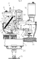
- figure 1 shows a lubricating device 1 for lubricating a cheese wheel 2 with a brush 3.
- Lubricating device comprises a support device 4, which is used for connection to a housing of a treatment device.
- a rocker 6 that can be pivoted about a rocker axis 5 is arranged on the support device 4 .
- the rocker 6 comprises a first rocker section 6a on a side of the rocker axis 5 facing the brush 3 .
- a fastening axis 7 pivotable connection to a brush device 8 is formed.
- the rocker 6 comprises on a side of the rocker axis 5 facing away from the brush 3 a second rocker section 6b on which a torque device 9 for setting a predetermined torque acting on the rocker 6 about the rocker axis 5 is arranged.
- the brush device 8 comprises a brush drive 10, which makes the brush 3, which is designed as a disc brush, rotatable about an axis aligned essentially perpendicularly to the surface of the cheese loaf.
- a feed 11 for liquid enables lubrication with liquid.
- the adjustable connection between the support device 4 and the brush device 8 is designed as a pivotable parallelogram connection with two arms and two short links.
- the first rocker section 6a forms one of the arms and is a connection between the rocker axis 5 and the fastening axis 7.
- a holding element 12 connected to the brush device 8 and a section of the support device 4 each form one of the short links.
- the short members extend from the fastening axis 7 or from the rocker axis 5 to the parallelogram axes 13.
- An arm 14 extends between the two parallelogram axes 13.
- the brush device 8 is arranged laterally to the rocker axis 5 and the resulting weight of the brush device 8 is transferred at a distance from the rocker axis 5 on a first side to the rocker 6, or to the first rocker section 6b.
- the torque device 9 comprises a weight 15 arranged at a distance from the rocker axis 5 on a second side on the rocker 6, or on the second rocker section 6b.
- the weight 15 is made up of weight segments 16, so that its size is determined by the Insertion or removal of weight segments 16 is variable.
- the weight 15 can be displaced along the second rocker section 6b, so that its distance from the rocker axis 5 can be adjusted.
- the torque device 9 includes an actuator 17 arranged on the support device 4, which makes the weight 15 arranged on the rocker 6 adjustable via a first actuating connection along the rocker 6.
- the first actuation connection includes outgoing by a shaft 18 rotatable by the actuator 17, a first crank 19 fastened to the shaft 18 and a connecting rod 20 leading from the free end of the first crank 19 to the weight 15.
- the brush device 8 Due to the integrated brush drive 10, the brush device 8 is relatively heavy. So that neither the weight 15 nor the length of the rocker 6 is too large for the positioning of the weight 15, the illustrated embodiment includes a relieving spring 21.
- the relieving spring 21 extends from the carrying device 4 to the brush device 8 or to its mounting element 12, and transfers a proportion of the weight of the brush device 8 to the support device 4 .
- the brush 3 can be adjusted from a working position on the wheel of cheese 2 to a parking position at a distance from the wheel of cheese 2 .
- This alternation between the two brush positions is achieved with the actuator 17.
- the actuator 17 and a second actuating connection make the rocker 6 pivotable into the parking position in which the brush 3 is lifted from the cheese loaf 2 .
- the rocker 6 is released again, so that the brush comes into contact with the cheese loaf 2 .
- the second actuating connection comprises a second crank 22 fastened to the rotatable shaft 18.
- Rollers 22a are arranged at the free end of the second crank 22, which engage under the first rocker section 6a and move it during the corresponding movement of the lift the second crank 22 (cf. 2 ). In this case, a force acts on the rocker 6 which opposes the resultant weight of the brush device 4 .
- figure 2 shows an embodiment with all elements of figure 1 , which also makes the wheel of cheese rotatable and the jar side lubricated.
- a rotatable turntable 23 is preferably set in rotation via a gear wheel 24 by a turntable drive, not shown.
- the turntable 23 and the brush device 8 are positioned relative to one another in such a way that the upper side of a cheese loaf 2 arranged on the turntable 23 can be brushed over by the brush 3 in an area extending from the grain side to beyond the middle of the surface.
- the lubricating device comprises an edge brush 25 rotatably arranged on the carrying device 4 so that the jerky side of the cheese loaf 2 can also be lubricated.
- a duct 11 supplies liquid to the edge brush 25. While the wheel of cheese 2 is rotated by the turntable 23, the edge brush lubricates 25 in a position adapted to the edge of the cheese the jar side.
Landscapes
- Life Sciences & Earth Sciences (AREA)
- Animal Husbandry (AREA)
- Environmental Sciences (AREA)
- Chemical & Material Sciences (AREA)
- Engineering & Computer Science (AREA)
- Food Science & Technology (AREA)
- Polymers & Plastics (AREA)
- Finish Polishing, Edge Sharpening, And Grinding By Specific Grinding Devices (AREA)
Abstract
Description
- Die Erfindung bezieht sich auf eine Schmiervorrichtung zum Schmieren von Käselaiben nach dem Oberbegriff des Anspruchs 1 und auf deren Verwendung.
- Bei der Käseherstellung wird Käsebruch in Formen gepresst und anschliessend werden die Käselaibe nebeneinander auf Käsebrettern in Lagern gereift. Während dieser Lagerung werden die Käselaibe regelmässig gewendet, so dass die grossen parallel verlaufenden Aussenflächen abwechselnd als Käseoberseite und Käseunterseite wahrgenommen werden. Die Aussenfläche eines Käselaibs wird von der Käseoberseite, der Käseunterseite und einer Järbseite gebildet, wobei die Järbseite die Käseoberseite mit der Käseunterseite verbindet. Die Järbseite wird auch als Käserand bezeichnet. Bei den meisten Käsen ist der Umfang der Ober- und Unterseite kreisförmig. Für Raclette oder andere Käse wird auch ein quadratischer Umfang gewählt, so dass diese Käselaibe zum Schneiden von flachen Stücken besser geeignet sind.
- Zum Erzielen einer gewünschten Reifung und einer härteren Oberfläche, bzw. einer Käserinde, wird die jeweilige Oberseite und die Järbseite mittels Bürsten mit einer vorzugsweise salzhaltigen Flüssigkeit behandelt. Diese Behandlung wird als Schmieren bezeichnet.
- Wenn beispielsweise Käselaibe 7kg schwer sind und während einer 15 Monate langen Reifezeit anfänglich täglich, später weniger oft, gewendet und abgerieben bzw. geschmiert werden, so ergibt sich für das Wenden und für das Schmieren ein grosser Arbeitsaufwand, der möglichst weitgehend mit Anlagen durchgeführt wird. Es gibt Anlagen mit stationären und solche mit mobilen Vorrichtungen zum Behandeln, bzw. Wenden und/oder Schmieren, von Käselaiben.
- Bei stationären Vorrichtungen sind Holzbretter mit Käselaiben in sogenannten Horden zusammengestellt und die Horden oder aus den Horden entnommene Stapel mit Brettern und Käselaiben werden beispielsweise von selbstfahrenden Transportgeräten zu einer stationären Vorrichtung transportiert. Nach der Behandlung der Käselaibe werden die Horden oder die Stapel wieder in den ihnen zugeordneten Lagerbereich transportiert.
- Bei einer selbstfahrenden Vorrichtung zum Behandeln von Käselaiben bewegt sich die Vorrichtung durch Lagergassen und behandelt bei der jeweils aktuellen Position seitlich der Gasse gelagerte Käselaibe. Die seitlich der Gasse auf Käsebrettern gelagerten Käselaibe werden auf den Käsebrettern von einer Fördereinrichtung zur Vorrichtung zum Behandeln gebracht und dann behandelt. Nach der Behandlung bringt die Fördereinrichtung die Bretter mit den Käselaiben wieder in eine Lagerposition. Wenn in der aktuellen Position der selbstfahrenden Vorrichtung, die von der Steuerung zum Behandeln vorgesehenen Käselaibe behandelt sind, bewegt sich die selbstfahrende Vorrichtung zur nächsten Position mit gelagerten Käselaiben und behandelt diese. Wenn die zum Behandeln vorgesehenen Käselaibe einer Gasse behandelt sind, kann die selbstfahrende Vorrichtung in einer nächsten Gasse eingesetzt werden.
-
EP 1 941 794 B1 zeigt ein Pflegegerät, welches seitlich einzelne Käselaibe aus einem Regal entnimmt, wendet und zur weiteren Behandlung auf einen Tisch legt. -
CH 420 714 -
WO 2012/172506 A1 beschreibt eine selbstfahrende Vorrichtung, bei der eine kombinierte Wende- und Schmiereinrichtung auf die jeweilige Regalhöhe bewegt wird, von der ein erstes Käsebrett mit mehreren Käselaiben in die Vorrichtung aufgenommen und dabei die Oberseite der Käselaibe gebürstet wird. Die Vorrichtung hält ein zweites Käsebrett bereit, dem die Oberseiten der Käselaibe zugeführt werden. Die beiden beidseits der Käselaibe angeordneten Käsebretter und die Käselaibe werden in einem ersten Schritt um 90° um eine parallel zu den Längsachsen der Käsebretter verlaufende Achse gedreht. Die Käselaibe gelangen dadurch in eine Lage, bei der ihre Unter- und Oberseiten vertikal ausgerichtet sind. Die umlaufende Randfläche liegt in einem unteren Bereich auf einem Antriebsband auf, mittels dem die Käselaibe in eine Drehung versetzt und dabei die Randflächen der Käselaibe gebürstet werden. Anschliessend werden die Käsebretter und die Käselaibe in einem zweiten Schritt um 90° um die parallel zu den Längsachsen der Käsebretter verlaufende Achse gedreht. Danach können die Käselaibe auf dem zweiten Käsebrett in das Regal geschoben werden. - Die Kombination des Wendens und Bürstens führt dazu, dass sich diese beiden Behandlungen gegenseitig unterbrechen und reduziert die Effizienz des Wendens und des Bürstens. Wenn junge, d.h. wenig gereifte, Käselaibe für das Bürsten des Randes auf dem Rand aufliegend gedreht werden, können diese Käselaibe beschädigt werden, weil sie dazu noch nicht genügend stabil sind. Aufgrund möglicher Verformungen ist die Position der dem Rand der Käselaibe zugeordneten Bürsten nicht immer optimal. Das Schmieren der Oberseiten der Käselaibe beim Aufnehmen der Käselaibe in die Vorrichtung ist für viele Käsesorten nicht genügend. Anpassungen der Positionen der zum Schmieren eingesetzten Bürsten an unterschiedliche Höhen der einzelnen Käselaibe sind nicht möglich.
- Die erfindungsgemässe Aufgabe besteht nun darin eine einfache Lösung zu finden, welche das Schmieren von Käselaiben optimal durchführbar macht.
- Diese Aufgabe wird durch eine Schmiervorrichtung mit den Merkmalen des Anspruchs 1 gelöst. Die abhängigen Ansprüche beschreiben alternative bzw. vorteilhafte
- Ausführungsvarianten, welche weitere Aufgaben lösen.
- Im Rahmen eines ersten erfinderischen Schrittes wurde erkannt, dass mit identischen Formen hergestellte Käselaibe unterschiedliche Abstände zwischen der Oberseite und der Unterseite, also unterschiedliche Höhen, aufweisen können. Wenn nun bei einem Käselaib, der auf einem Drehteller liegt, gemäss einer handelsüblichen Lösung die Tellerbürste zum Behandeln der Oberseite auf einer festen, vorgegebenen Höhe positioniert wird, so hängt die Anpresskraft, mit der die Bürste auf die Oberseite des Käselaibs wirkt, auch von der jeweiligen Höhe dieses Käselaibs ab. Für ein optimales Schmieren soll eine vorgegebene Anpresskraft der Bürste auch bei unterschiedlichen Käsehöhen genügend genau gewährleistet sein. Zudem soll die bei unterschiedlichen Käsehöhen im Wesentlichen gleiche Anpresskraft der Bürste verstellbar sein, so dass eine an die Art und/oder den Reifegrad des jeweiligen Käselaibs angepasste vorgegebene Anpresskraft erzielbar ist.
- In einem zweiten erfinderischen Schritt wurde erkannt, dass eine einstellbare und nach der Einstellung bei unterschiedlichen Käsehöhen im Wesentlichen gleichbleibende Anpresskraft erzielbar ist, wenn die Schmiervorrichtung eine um eine Wippenachse schwenkbare Wippe und daran angeordnet eine Bürsteneinrichtung mit einer Bürste umfasst. Die Wippenachse verläuft im Wesentlichen horizontal, so dass das Gewicht der Bürsteneinrichtung ein auf die Wippe um die Wippenachse wirkendes erstes Drehmoment erzielt. Die Schmiervorrichtung umfasst zudem eine verstellbare Drehmomenteinrichtung zum Einstellen eines auf die Wippe um die Wippenachse wirkenden zweiten Drehmomentes. Aus der Überlagerung der vom Gewicht der Bürsteneinrichtung (8) und von der Drehmomenteinrichtung stammenden Drehmomente geht ein resultierendes Drehmoment hervor, welches zu einer Anpresskraft der Bürste (3) an eine Käseoberfläche führt. Eine gewünschte Anpresskraft kann somit mit einer entsprechenden Einstellung des zweiten Drehmoments durch die Drehmomenteinrichtung erzielt werden. Diese Anpresskraft bleibt im Wesentlichen gleich, auch wenn die Wippe aufgrund von unterschiedlichen Käsehöhen unterschiedlich geneigt ist.
- Die erfindungsgemässe Schmiervorrichtung zum Schmieren von Käselaiben umfasst eine Trageinrichtung und mindestens eine Bürsteneinrichtung. Die Bürsteneinrichtung ist über eine verstellbare Verbindung mit der Trageinrichtung verbunden und umfasst eine Bürste, die mit einer Anpresskraft an eine Oberseite des Käselaibs anlegbar ist. Die Schmiervorrichtung umfasst zudem eine um eine Wippenachse schwenkbare Wippe und eine Drehmomenteinrichtung zum Einstellen eines um die Wippenachse auf die Wippe wirkenden vorgebbaren Drehmomentes. Die Wippenachse ist an der Trageinrichtung positioniert. Die Bürsteneinrichtung ist so an der Wippe angeordnet, dass eine resultierende Gewichtskraft der Bürsteneinrichtung in einem Abstand zur Wippenachse auf die Wippe übertragen wird.
- Gemäss einer vorteilhaften Ausführungsform umfasst die Drehmomenteinrichtung ein in einem Abstand zur Wippenachse an der Wippe angeordnetes Gewicht, dessen Grösse verstellbar ist. Zum Verstellen des Gewichtes können beispielsweise einzelne Gewichtssegmente eingesetzt oder entfernt werden, was mit viel Aufwand und wenig Flexibilität verbunden ist.
- Gemäss einer weiteren vorteilhaften Ausführungsform umfasst die Drehmomenteinrichtung ein in einem Abstand zur Wippenachse an der Wippe angeordnetes Gewicht, dessen Abstand von der Wippenachse einstellbar ist.
- Zum Einstellen eines gewünschten Abstandes umfasst die Drehmomenteinrichtung vorzugsweise einen Stellantrieb, der das an der Wippe angeordnete Gewicht über eine erste Betätigungsverbindung entlang der Wippe verstellbar macht. Dazu kann die erste Betätigungsverbindung ausgehend von einer vom Stellantrieb drehbaren Welle eine an der Welle befestigte erste Kurbel und einen vom freien Ende der ersten Kurbel zum Gewicht führenden Pleuel umfassen.
- Wenn die Bürste von einer Arbeitsposition zu einer Parkposition verstellbar sein soll, so wird der Wechsel zwischen diesen Positionen vorzugsweise mit dem Stellantrieb erzielt. Der Stellantrieb und eine zweite Betätigungsverbindung machen die Wippe in die Parkposition schwenkbar, bei der die Bürste vom Käselaib abgehoben ist.
- Mit einer entgegengesetzten Bewegung der zweiten Betätigungsverbindung wird die Wippe wieder freigegeben, so dass die Bürste in Kontakt zum Käselaib tritt.
- Die zweite Betätigungsverbindung umfasst beispielsweise eine an der drehbaren Welle befestigte zweite Kurbel, welche mit einer Kraft auf die Wippe wirken kann, die der resultierende Gewichtskraft der Bürsteneinrichtung entgegengesetzt ist.
- Gemäss weiterer Ausführungsformen wird, das von der verstellbaren Drehmomenteinrichtung erzeugte, zweite Drehmoment durch eine auf die Wippe wirkende verstellbare Kraft erzielt. Vorzugsweise stammt die auf die Wippe wirkende Kraft von einem Federelement, insbesondere von einer mechanischen Feder, wobei die Befestigungsenden des Federelements bzw. der Feder an der Wippe und an einer mit der Trageinrichtung verbundenen Halterung befestigt sind. Zum Verstellen der vom Federelement auf die Wippe wirkenden Kraft, bzw. des von der Kraft bewirkten zweiten Drehmoments, kann der Angriffspunkt des Federelements an der Wippe von der Schwenkachse weg oder auf diese zu verstellt werden, während die Position der Halterung festbleibt. Die vom Federelement auf die Wippe wirkende Kraft, bzw. das von der Kraft bewirkte zweite Drehmoment, kann auch durch eine Änderung des Abstandes der Halterung vom Angriffspunkt des Federelements an der Wippe erzielt werden.
- Wenn die Bürsteneinrichtung einen Bürstenantrieb umfasst, kann dieser die als Tellerbürste ausgebildete Bürste um eine im Wesentlichen senkrecht zur Käseoberfläche ausgerichtete Achse drehen. Dies ist für eine optimale Schmierung vorteilhaft.
- Die verstellbare Verbindung zwischen der Trageinrichtung und der Bürsteneinrichtung ist vorzugsweise als schwenkbare Parallelogramm-Verbindung mit zwei Armen und zwei kurzen Gliedern ausgebildet, wobei die Arme schwenkbar mit den Gliedern verbunden sind. Ein Arm ist ein Abschnitt der Wippe und der andere Arm erstreckt sich von der Trageinrichtung zur Bürsteneinrichtung. Die kurzen Glieder werden von einem Abschnitt der Trageinrichtung und von einem Abschnitt der Bürsteneinrichtung gebildet. Mit dieser Parallelogramm-Verbindung kann gewährleistet werden, dass die Tellerbürste bei allen Kipplagen der Wippe gleich ausgerichtet ist und darum in optimaler Ausrichtung auf die Käseoberfläche wirkt.
- Wenn die Bürsteneinrichtung schwer ist, kann die Länge der Wippe, die für das Positionieren des Gewichtes benötigt wird, gross werden. Mit einer Entlastungsfeder in der verstellbaren Verbindung kann eine kürzere Wippe verwendet werden. Die Entlastungsfeder erstreckt sich von der Trageinrichtung zur Bürsteneinrichtung und überträgt einen Teil des Gewichts der Bürsteneinrichtung an die Trageinrichtung.
- Bei einer vorteilhaften Ausführungsform umfasst die Schmiereinrichtung einen an der Trageinrichtung drehbar angeordneten Drehteller. Der Drehteller und die Bürsteneinrichtung sind so relativ zueinander positioniert, dass die Oberseite eines auf dem Drehteller angeordneten Käselaibs von der Bürste in einem von der Järbseite bis über die Mitte der Oberfläche hinausgehenden Bereich überstrichen werden kann.
- Damit die Oberseite und die Järbseite geschmiert werden kann, umfasst die Schmiervorrichtung auch eine an der Trageinrichtung drehbar angeordnete Randbürste. Zu beiden Bürsten führt eine Zuführung für Flüssigkeit. Während der Käselaib auf dem Drehteller dreht, schmiert die Tellerbürste mit einer vorgebbaren Anpresskraft die Käseoberfläche und die Randbürste mit an den Käserand angepasster Position die Järbseite.
- Die erfindungsgemässe Schmiervorrichtung wird in einer Vorrichtung zum Behandeln von Käselaiben vorzugsweise zusammen mit einer Wendeeinrichtung eingesetzt. Solche Behandlungsvorrichtungen umfassen zudem eine Zuführeinrichtung und eine Übergabeeinrichtung. Die Zuführeinrichtung macht mindestens zwei auf einem Käsebrett entlang einer Anordnungsachse nebeneinander angeordnete Käselaibe der Wendeeinrichtung zuführbar. Die gewendeten Käselaibe werden von der Übergabeeinrichtung an mindestens zwei nebeneinander angeordnete erfindungsgemässe Schmiervorrichtung übergeben. Die geschmierten Käselaibe werden von der Übergabeeinrichtung auf ein Käsebrett gebracht, auf dem sie dann beispielsweise zu einem Lagerplatz gebracht werden. Eine vorteilhafte Behandlungsvorrichtung umfasst eine Fördereinrichtung zum Fördern von Käsebrettern mit Käselaiben zwischen Lagerplätzen und der Zuführeinrichtung bzw. der Übergabeeinrichtung.
- Anhand der Figuren wird die Erfindung im Folgenden näher beschrieben. Dabei zeigen
- Figur 1
- eine Seitenansicht einer Schmiervorrichtung und einem darunter angeordneten Käselaib,
- Figur 2
- eine Seitenansicht einer Schmiervorrichtung gemäss
Figur 1 , die zusätzlich einen Drehteller und eine Seitenbürste umfasst. -
Figur 1 zeigt eine Schmiervorrichtung 1 zum Schmieren eines Käselaibs 2 mit einer Bürste 3. Die - Schmiervorrichtung umfasst eine Trageinrichtung 4, die zur Verbindung mit einem Gehäuse einer Behandlungsvorrichtung dient. An der Trageinrichtung 4 ist eine um eine Wippenachse 5 schwenkbare Wippe 6 angeordnet. In der dargestellten Ausführung umfasst die Wippe 6 auf einer der Bürste 3 zugewandten Seite der Wippenachse 5 einen ersten Wippenabschnitt 6a. Beim freien Ende des ersten Wippenabschnitts 6a ist eine um eine Befestigungsachse 7 schwenkbare Verbindung zu einer Bürsteneinrichtung 8 ausgebildet. Die Wippe 6 umfasst auf einer von der Bürste 3 abgewandten Seite der Wippenachse 5 einen zweiten Wippenabschnitt 6b, an dem eine Drehmomenteinrichtung 9 zum Einstellen eines um die Wippenachse 5 auf die Wippe 6 wirkenden vorgebbaren Drehmomentes angeordnet ist.
- In der dargestellten Ausführung umfasst die Bürsteneinrichtung 8 einen Bürstenantrieb 10, welcher die als Tellerbürste ausgebildete Bürste 3 um eine im Wesentlichen senkrecht zur Oberfläche des Käselaibs ausgerichtete Achse drehbar macht. Eine Zuführung 11 für Flüssigkeit ermöglicht die Schmierung mit Flüssigkeit.
- Die verstellbare Verbindung zwischen der Trageinrichtung 4 und der Bürsteneinrichtung 8 ist als schwenkbare Parallelogramm-Verbindung mit zwei Armen und zwei kurzen Gliedern ausgebildet. Der ersten Wippenabschnitt 6a bildet einen der Arme und ist eine Verbindung zwischen der Wippenachse 5 und der Befestigungsachse 7. Ein mit der Bürsteneinrichtung 8 verbundenes Halterungselement 12 und ein Abschnitt der Trageinrichtung 4 bilden je eines der kurzen Glieder. Die kurzen Glieder erstrecken sich von der Befestigungsachse 7 bzw. von der Wippenachse 5 zu Parallelogramm-Achsen 13. Zwischen den beiden Parallelogramm-Achsen 13 erstreckt sich ein Arm 14. Mit dieser Parallelogramm-Verbindung kann gewährleistet werden, dass die Tellerbürste bei allen Kipplagen der Wippe gleich ausgerichtet ist und darum in optimaler Ausrichtung auf die Käseoberfläche wirkt.
- Mit der Parallelogramm-Verbindung ist die Bürsteneinrichtung 8 seitlich zur Wippenachse 5 angeordnet und die resultierende Gewichtskraft der Bürsteneinrichtung 8 wird in einem Abstand zur Wippenachse 5 auf einer ersten Seite auf die Wippe 6, bzw. auf den ersten Wippenabschnitt 6b, übertragen.
- In der dargestellten Ausführungsform umfasst die Drehmomenteinrichtung 9 ein in einem Abstand zur Wippenachse 5 auf einer zweiten Seite an der Wippe 6, bzw. am zweiten Wippenabschnitt 6b, angeordnetes Gewicht 15. Das Gewicht 15 ist aus Gewichtssegmenten 16 zusammengestellt, so dass dessen Grösse durch das Einsetzen oder Entfernen von Gewichtssegmenten 16 veränderbar ist.
- Das Gewicht 15 ist entlang des zweiten Wippenabschnitt 6b verschiebbar, so dass dessen Abstand zur Wippenachse 5 einstellbar ist.
- Zum Einstellen eines gewünschten Abstandes umfasst die Drehmomenteinrichtung 9 einen an der Trageinrichtung 4 angeordneten Stellantrieb 17, der das an der Wippe 6 angeordnete Gewicht 15 über eine erste Betätigungsverbindung entlang der Wippe 6 verstellbar macht. Die erste Betätigungsverbindung umfasst ausgehend von einer vom Stellantrieb 17 drehbaren Welle 18 eine an der Welle 18 befestigte erste Kurbel 19 und einen vom freien Ende der ersten Kurbel 19 zum Gewicht 15 führenden Pleuel 20.
- Aufgrund des integrierten Bürstenantriebs 10 ist die Bürsteneinrichtung 8 relativ schwer. Damit weder das Gewicht 15 noch die Länge der Wippe 6 für das Positionieren des Gewichtes 15 allzu gross wird, umfasst die dargestellte Ausführung eine Entlastungsfeder 21. Die Entlastungsfeder 21 erstreckt sich von der Trageinrichtung 4 zur Bürsteneinrichtung 8, bzw. zu deren Halterungselement 12, und überträgt einen Anteil des Gewichts der Bürsteneinrichtung 8 an die Trageinrichtung 4 .
- Bei der dargestellten Ausführung ist die Bürste 3 von einer Arbeitsposition beim Käselaib 2 zu einer Parkposition in einem Abstand zum Käselaib 2 verstellbar. Dieser Wechsel zwischen den beiden Bürstenpositionen wird mit dem Stellantrieb 17 erzielt. Der Stellantrieb 17 und eine zweite Betätigungsverbindung machen die Wippe 6 in die Parkposition schwenkbar, bei der die Bürste 3 vom Käselaib 2 abgehoben ist. Mit einer entgegengesetzten Bewegung der zweiten Betätigungsverbindung wird die Wippe 6 wieder freigegeben, so dass die Bürste in Kontakt zum Käselaib 2 tritt.
- Um die Wippe 6 in die Parkposition zu schwenken umfasst die zweite Betätigungsverbindung eine an der drehbaren Welle 18 befestigte zweite Kurbel 22. Am freien Ende der zweiten Kurbel 22 sind Rollen 22a angeordnet, die unter den ersten Wippenabschnitt 6a greifen und diesen bei der entsprechenden Bewegung der zweiten Kurbel 22 anheben (vgl.
Fig. 2 ). Dabei wirkt eine Kraft auf die Wippe 6, die der resultierende Gewichtskraft der Bürsteneinrichtung 4 entgegengesetzt ist. -
Figur 2 zeigt eine Ausführungsform mit allen Elementen derFigur 1 , die zusätzlich den Käselaib drehbar und die Järbseite schmierbar macht. Ein drehbarer Drehteller 23 wird vorzugsweise über ein Zahnrad 24 von einem nicht dargestellten Drehteller-Antrieb in Drehung versetzt. Der Drehteller 23 und die Bürsteneinrichtung 8 sind so relativ zueinander positioniert, dass die Oberseite eines auf dem Drehteller 23 angeordneten Käselaibs 2 von der Bürste 3 in einem von der Järbseite bis über die Mitte der Oberfläche hinausgehenden Bereich überstreichbar ist. - Damit auch die Järbseite des Käselaibs 2 geschmiert werden kann, umfasst die Schmiervorrichtung eine an der Trageinrichtung 4 drehbar angeordnete Randbürste 25. Um die Randbürste 25 zu drehen, ist ein Randbürsten-Antrieb 26 mit der Randbürste 25 verbunden. Eine Zuführung 11 führt Flüssigkeit zur Randbürste 25. Während der Käselaib 2 vom Drehteller 23 gedreht wird, schmiert die Randbürste 25 in einer an den Käserand angepassten Position die Järbseite.
Claims (13)
- Schmiervorrichtung (1) zum Schmieren von Käselaiben (2) mit einer Trageinrichtung (4) und einer Bürsteneinrichtung (8), wobei die Bürsteneinrichtung (8) über eine verstellbare Verbindung mit der Trageinrichtung (4) verbunden ist und eine Bürste (3) umfasst, die mit einer Anpresskraft an eine Oberseite des Käselaibs (2) anlegbar ist, dadurch gekennzeichnet, dass die Schmiervorrichtung (1) eine um eine Wippenachse (5) schwenkbare Wippe (6) und eine Drehmomenteinrichtung (9) zum Einstellen eines um die Wippenachse (5) auf die Wippe (6) wirkenden vorgebbaren Drehmomentes umfasst, wobei die Wippenachse (5) an der Trageinrichtung (4) positioniert ist, die Bürsteneinrichtung (8) an der Wippe (6) angeordnet ist und eine resultierende Gewichtskraft der Bürsteneinrichtung (8) in einem Abstand zur Wippenachse (5) auf die Wippe (6) übertragen wird.
- Schmiervorrichtung (1) nach Anspruch 1, dadurch gekennzeichnet, dass die Drehmomenteinrichtung (9) ein in einem Abstand zur Wippenachse (5) an der Wippe (6) angeordnetes Gewicht (15) umfasst, wobei dessen Grösse verstellbar ist.
- Schmiervorrichtung (1) nach Anspruch 1 oder 2, dadurch gekennzeichnet, dass die Drehmomenteinrichtung (9) ein in einem Abstand zur Wippenachse (5) an der Wippe (6) angeordnetes Gewicht (15) umfasst und dessen Abstand von der Wippenachse (5) einstellbar macht.
- Schmiervorrichtung (1) nach Anspruch 3, dadurch gekennzeichnet, dass die Drehmomenteinrichtung (9) einen Stellantrieb (17) umfasst, der das an der Wippe (6) angeordnete Gewicht (15) über eine erste Betätigungsverbindung entlang der Wippe (6) verstellbar macht.
- Schmiervorrichtung (1) nach Anspruch 4, dadurch gekennzeichnet, dass die erste Betätigungsverbindung ausgehend von einer vom Stellantrieb (17) drehbaren Welle (18) eine an der Welle (18) befestigte erste Kurbel (19) und einen vom freien Ende der ersten Kurbel (19) zum Gewicht (15) führenden Pleuel (20) umfasst.
- Schmiervorrichtung (1) nach Anspruch 4 oder 5, dadurch gekennzeichnet, dass der Stellantrieb (17) über eine zweite Betätigungsverbindung die Wippe (6) in eine Parkposition mit vom Käselaib abgehobener Bürste (3) schwenkbar macht.
- Schmiervorrichtung (1) nach Anspruch 6, dadurch gekennzeichnet, dass die zweite Betätigungsverbindung eine an der drehbaren Welle (18) befestigte zweite Kurbel (22) umfasst, welche mit einer Kraft auf die Wippe (6) wirkt, die der resultierende Gewichtskraft der Bürsteneinrichtung (8) entgegengesetzt ist.
- Schmiervorrichtung (1) nach einem der Ansprüche 1 bis 7, dadurch gekennzeichnet, dass die Bürsteneinrichtung (8) einen Bürstenantrieb (10) umfasst, der die als Tellerbürste ausgebildete Bürste (3) um eine im Wesentlichen senkrecht zur Käseoberfläche ausgerichtete Achse drehbar macht.
- Schmiervorrichtung (1) nach einem der Ansprüche 1 bis 8, dadurch gekennzeichnet, dass die verstellbare Verbindung zwischen der Trageinrichtung (4) und der Bürsteneinrichtung (8) als schwenkbare Parallelogramm-Verbindung mit zwei Armen und zwei kurzen Gliedern ausgebildet ist, wobei die Arme an der Wippe (6) sowie von der Trageinrichtung (4) zur Bürsteneinrichtung (8) und die kurzen Glieder an der Trageinrichtung (4) sowie an der Bürsteneinrichtung (8) ausgebildet sind.
- Schmiervorrichtung (1) nach einem der Ansprüche 1 bis 9, dadurch gekennzeichnet, dass die verstellbare Verbindung zwischen der Trageinrichtung (4) und der Bürsteneinrichtung (8) eine Entlastungsfeder (21) umfasst, welche einen Anteil der resultierenden Gewichtskraft reduziert.
- Schmiervorrichtung (1) nach einem der Ansprüche 1 bis 9, dadurch gekennzeichnet, dass an der Trageinrichtung (4) ein Drehteller (23) drehbar angeordnet ist, wobei der Drehteller (23) und die Bürsteneinrichtung (8) so relativ zueinander positioniert sind, dass die Oberseite eines auf dem Drehteller (23) angeordneten Käselaibs (2) von der Bürste (3) in einem von der Järbseite bis über die Mitte der Oberfläche hinausgehenden Bereich kontaktierbar ist.
- Schmiervorrichtung (1) nach Anspruch 11, dadurch gekennzeichnet, dass die Schmiervorrichtung (1) auch eine an der Trageinrichtung (4) drehbar angeordnete Randbürste (25) umfasst, wobei die Randbürste (25) in einer an den Käserand angepassten Position die Järbseite schmierbar macht.
- Verwendung von mindestens zwei Schmiervorrichtungen (1) nach einem der Ansprüche 1 bis 12 in einer Vorrichtung zum gleichzeitigen Schmieren von mindestens zwei Käselaiben (2).
Applications Claiming Priority (1)
| Application Number | Priority Date | Filing Date | Title |
|---|---|---|---|
| CH01637/20A CH718201A1 (de) | 2020-12-21 | 2020-12-21 | Schmiervorrichtung zum Schmieren von Käselaiben. |
Publications (3)
| Publication Number | Publication Date |
|---|---|
| EP4014726A1 true EP4014726A1 (de) | 2022-06-22 |
| EP4014726B1 EP4014726B1 (de) | 2025-03-26 |
| EP4014726C0 EP4014726C0 (de) | 2025-03-26 |
Family
ID=78827983
Family Applications (1)
| Application Number | Title | Priority Date | Filing Date |
|---|---|---|---|
| EP21213388.8A Active EP4014726B1 (de) | 2020-12-21 | 2021-12-09 | Schmiervorrichtung zum schmieren von käselaiben |
Country Status (2)
| Country | Link |
|---|---|
| EP (1) | EP4014726B1 (de) |
| CH (1) | CH718201A1 (de) |
Citations (6)
| Publication number | Priority date | Publication date | Assignee | Title |
|---|---|---|---|---|
| CH420714A (de) | 1963-01-08 | 1966-09-15 | Schmid Peter | Maschine zum Behandeln, Umlagern und Wenden von Käselaiben |
| FR1530488A (fr) * | 1967-04-20 | 1968-06-28 | Appareillage pour le traitement des meules de gruyère | |
| EP1941794B1 (de) | 2007-01-03 | 2009-08-19 | Leu Anlagenbau AG | Käsepflegeroboter |
| US7592029B1 (en) * | 2003-05-29 | 2009-09-22 | Sargento Foods, Inc. | Method and apparatus for slicing small cheese portions and preparing cheese loaves for slicing |
| ITMI20090854A1 (it) * | 2009-05-15 | 2010-11-16 | Aldo Piazza | Apparecchiatura per la pulitura della crosta di forme di formaggio |
| WO2012172506A1 (fr) | 2011-06-17 | 2012-12-20 | P.M.S. Equipement | Dispositif de traitement de fromages |
Family Cites Families (2)
| Publication number | Priority date | Publication date | Assignee | Title |
|---|---|---|---|---|
| RU2027352C1 (ru) * | 1991-06-03 | 1995-01-27 | Научно-исследовательский технологический институт приборостроения | Устройство для мойки головок сыра |
| DE19513176C1 (de) * | 1995-03-31 | 1996-09-12 | Groh Prischmann & Schulz Forsc | Verfahren und Vorrichtung zur Andruckregelung für rotierende Werkzeuge |
-
2020
- 2020-12-21 CH CH01637/20A patent/CH718201A1/de unknown
-
2021
- 2021-12-09 EP EP21213388.8A patent/EP4014726B1/de active Active
Patent Citations (6)
| Publication number | Priority date | Publication date | Assignee | Title |
|---|---|---|---|---|
| CH420714A (de) | 1963-01-08 | 1966-09-15 | Schmid Peter | Maschine zum Behandeln, Umlagern und Wenden von Käselaiben |
| FR1530488A (fr) * | 1967-04-20 | 1968-06-28 | Appareillage pour le traitement des meules de gruyère | |
| US7592029B1 (en) * | 2003-05-29 | 2009-09-22 | Sargento Foods, Inc. | Method and apparatus for slicing small cheese portions and preparing cheese loaves for slicing |
| EP1941794B1 (de) | 2007-01-03 | 2009-08-19 | Leu Anlagenbau AG | Käsepflegeroboter |
| ITMI20090854A1 (it) * | 2009-05-15 | 2010-11-16 | Aldo Piazza | Apparecchiatura per la pulitura della crosta di forme di formaggio |
| WO2012172506A1 (fr) | 2011-06-17 | 2012-12-20 | P.M.S. Equipement | Dispositif de traitement de fromages |
Also Published As
| Publication number | Publication date |
|---|---|
| CH718201A1 (de) | 2022-06-30 |
| EP4014726B1 (de) | 2025-03-26 |
| EP4014726C0 (de) | 2025-03-26 |
Similar Documents
| Publication | Publication Date | Title |
|---|---|---|
| DE60101427T2 (de) | Vacuum-Tisch-Vorrichtung zum Stützen und Halten einer Glasscheibe | |
| DE1482908A1 (de) | Heuwerbungsmaschine | |
| DE3335430C2 (de) | ||
| DE3533496A1 (de) | Foerderer-gehaenge mit griffelement auf lagerfeder | |
| DE102018132655A1 (de) | Umsetzanlage sowie Umsetzverfahren | |
| EP4014726B1 (de) | Schmiervorrichtung zum schmieren von käselaiben | |
| DE3916594A1 (de) | Tisch mit einstellbarer woelbung fuer abkantpressen, richtplatten und aehnliche vorrichtungen | |
| EP4014727B1 (de) | Schmiervorrichtung zum schmieren der järbseiten von käselaiben | |
| EP4405281A1 (de) | Vereinzelungsvorrichtung für profile | |
| CH644821A5 (de) | Rollenfuehrungsschuh fuer aufzuege. | |
| DE1507290A1 (de) | Maehmaschine | |
| EP4014725A1 (de) | Wendevorrichtung zum wenden von käselaiben | |
| DE2438607A1 (de) | Lege- und transportvorrichtung fuer flaechengebilde | |
| CH422628A (de) | Vorrichtung zum Trennen und Abgeben von Behältern aus einem Stapel | |
| DE69511226T2 (de) | Vorrichtung zum Behandeln von Gegenständen | |
| DE102023112767B4 (de) | Tafelschere mit Blechhochhaltevorrichtung | |
| DE69902518T2 (de) | Ausrichtungseinrichtung und maschine mit solchen einrichtungen | |
| DE3401233C2 (de) | ||
| EP0120811B1 (de) | Verfahren und Maschine zum vollautomatischen Schmieren, Waschen und Entfernen von Schmiere von Käselaiben und eine Beschickungsanlage | |
| EP1700522B1 (de) | Wendevorrichtung für Käsehorden | |
| DE719344C (de) | Maschine zum automatischen Herstellen und Loeten von Zinkpolsteckerbuchsen aus Blech sowie zum Anloeten von Drahtverbindungen an die Zinkbecher galvanischer Elemente | |
| DE2206479A1 (de) | Vorrichtung zum Einspannen und Abgeben eines Werkstücks | |
| DE69819339T2 (de) | Vorrichtung zum reduzieren der wurzelenden von baumstämmen | |
| DE2057212C3 (de) | Zusatzeinrichtung zum Schneiden und Ausstechen von Teigbändern, zum Anbau an eine Teigausrollmaschine | |
| DE2430398B2 (de) | Stuetzvorrichtung fuer an eine zugmaschine anbaubare landwirtschaftliche erntegeraete |
Legal Events
| Date | Code | Title | Description |
|---|---|---|---|
| PUAI | Public reference made under article 153(3) epc to a published international application that has entered the european phase |
Free format text: ORIGINAL CODE: 0009012 |
|
| STAA | Information on the status of an ep patent application or granted ep patent |
Free format text: STATUS: THE APPLICATION HAS BEEN PUBLISHED |
|
| AK | Designated contracting states |
Kind code of ref document: A1 Designated state(s): AL AT BE BG CH CY CZ DE DK EE ES FI FR GB GR HR HU IE IS IT LI LT LU LV MC MK MT NL NO PL PT RO RS SE SI SK SM TR |
|
| STAA | Information on the status of an ep patent application or granted ep patent |
Free format text: STATUS: REQUEST FOR EXAMINATION WAS MADE |
|
| RBV | Designated contracting states (corrected) |
Designated state(s): AL AT BE BG CH CY CZ DE DK EE ES FI FR GB GR HR HU IE IS IT LI LT LU LV MC MK MT NL NO PL PT RO RS SE SI SK SM TR |
|
| 17P | Request for examination filed |
Effective date: 20221124 |
|
| GRAP | Despatch of communication of intention to grant a patent |
Free format text: ORIGINAL CODE: EPIDOSNIGR1 |
|
| STAA | Information on the status of an ep patent application or granted ep patent |
Free format text: STATUS: GRANT OF PATENT IS INTENDED |
|
| GRAJ | Information related to disapproval of communication of intention to grant by the applicant or resumption of examination proceedings by the epo deleted |
Free format text: ORIGINAL CODE: EPIDOSDIGR1 |
|
| STAA | Information on the status of an ep patent application or granted ep patent |
Free format text: STATUS: REQUEST FOR EXAMINATION WAS MADE |
|
| GRAP | Despatch of communication of intention to grant a patent |
Free format text: ORIGINAL CODE: EPIDOSNIGR1 |
|
| STAA | Information on the status of an ep patent application or granted ep patent |
Free format text: STATUS: GRANT OF PATENT IS INTENDED |
|
| INTG | Intention to grant announced |
Effective date: 20241025 |
|
| INTC | Intention to grant announced (deleted) | ||
| INTG | Intention to grant announced |
Effective date: 20241121 |
|
| GRAS | Grant fee paid |
Free format text: ORIGINAL CODE: EPIDOSNIGR3 |
|
| GRAA | (expected) grant |
Free format text: ORIGINAL CODE: 0009210 |
|
| STAA | Information on the status of an ep patent application or granted ep patent |
Free format text: STATUS: THE PATENT HAS BEEN GRANTED |
|
| AK | Designated contracting states |
Kind code of ref document: B1 Designated state(s): AL AT BE BG CH CY CZ DE DK EE ES FI FR GB GR HR HU IE IS IT LI LT LU LV MC MK MT NL NO PL PT RO RS SE SI SK SM TR |
|
| REG | Reference to a national code |
Ref country code: GB Ref legal event code: FG4D Free format text: NOT ENGLISH |
|
| REG | Reference to a national code |
Ref country code: CH Ref legal event code: EP |
|
| REG | Reference to a national code |
Ref country code: DE Ref legal event code: R096 Ref document number: 502021007015 Country of ref document: DE |
|
| REG | Reference to a national code |
Ref country code: IE Ref legal event code: FG4D Free format text: LANGUAGE OF EP DOCUMENT: GERMAN |
|
| U01 | Request for unitary effect filed |
Effective date: 20250417 |
|
| U07 | Unitary effect registered |
Designated state(s): AT BE BG DE DK EE FI FR IT LT LU LV MT NL PT RO SE SI Effective date: 20250424 |
|
| PG25 | Lapsed in a contracting state [announced via postgrant information from national office to epo] |
Ref country code: RS Free format text: LAPSE BECAUSE OF FAILURE TO SUBMIT A TRANSLATION OF THE DESCRIPTION OR TO PAY THE FEE WITHIN THE PRESCRIBED TIME-LIMIT Effective date: 20250626 |
|
| PG25 | Lapsed in a contracting state [announced via postgrant information from national office to epo] |
Ref country code: NO Free format text: LAPSE BECAUSE OF FAILURE TO SUBMIT A TRANSLATION OF THE DESCRIPTION OR TO PAY THE FEE WITHIN THE PRESCRIBED TIME-LIMIT Effective date: 20250626 |
|
| PG25 | Lapsed in a contracting state [announced via postgrant information from national office to epo] |
Ref country code: HR Free format text: LAPSE BECAUSE OF FAILURE TO SUBMIT A TRANSLATION OF THE DESCRIPTION OR TO PAY THE FEE WITHIN THE PRESCRIBED TIME-LIMIT Effective date: 20250326 |
|
| PG25 | Lapsed in a contracting state [announced via postgrant information from national office to epo] |
Ref country code: GR Free format text: LAPSE BECAUSE OF FAILURE TO SUBMIT A TRANSLATION OF THE DESCRIPTION OR TO PAY THE FEE WITHIN THE PRESCRIBED TIME-LIMIT Effective date: 20250627 |
|
| PG25 | Lapsed in a contracting state [announced via postgrant information from national office to epo] |
Ref country code: SM Free format text: LAPSE BECAUSE OF FAILURE TO SUBMIT A TRANSLATION OF THE DESCRIPTION OR TO PAY THE FEE WITHIN THE PRESCRIBED TIME-LIMIT Effective date: 20250326 |
|
| PG25 | Lapsed in a contracting state [announced via postgrant information from national office to epo] |
Ref country code: ES Free format text: LAPSE BECAUSE OF FAILURE TO SUBMIT A TRANSLATION OF THE DESCRIPTION OR TO PAY THE FEE WITHIN THE PRESCRIBED TIME-LIMIT Effective date: 20250326 |
|
| PG25 | Lapsed in a contracting state [announced via postgrant information from national office to epo] |
Ref country code: PL Free format text: LAPSE BECAUSE OF FAILURE TO SUBMIT A TRANSLATION OF THE DESCRIPTION OR TO PAY THE FEE WITHIN THE PRESCRIBED TIME-LIMIT Effective date: 20250326 |
|
| PG25 | Lapsed in a contracting state [announced via postgrant information from national office to epo] |
Ref country code: SK Free format text: LAPSE BECAUSE OF FAILURE TO SUBMIT A TRANSLATION OF THE DESCRIPTION OR TO PAY THE FEE WITHIN THE PRESCRIBED TIME-LIMIT Effective date: 20250326 |
|
| PG25 | Lapsed in a contracting state [announced via postgrant information from national office to epo] |
Ref country code: IS Free format text: LAPSE BECAUSE OF FAILURE TO SUBMIT A TRANSLATION OF THE DESCRIPTION OR TO PAY THE FEE WITHIN THE PRESCRIBED TIME-LIMIT Effective date: 20250726 |
|
| REG | Reference to a national code |
Ref country code: CH Ref legal event code: U11 Free format text: ST27 STATUS EVENT CODE: U-0-0-U10-U11 (AS PROVIDED BY THE NATIONAL OFFICE) Effective date: 20260101 |
|
| PGFP | Annual fee paid to national office [announced via postgrant information from national office to epo] |
Ref country code: GB Payment date: 20251218 Year of fee payment: 5 |
|
| PG25 | Lapsed in a contracting state [announced via postgrant information from national office to epo] |
Ref country code: CZ Free format text: LAPSE BECAUSE OF FAILURE TO SUBMIT A TRANSLATION OF THE DESCRIPTION OR TO PAY THE FEE WITHIN THE PRESCRIBED TIME-LIMIT Effective date: 20250326 |
|
| U20 | Renewal fee for the european patent with unitary effect paid |
Year of fee payment: 5 Effective date: 20251222 |
|
| PLBE | No opposition filed within time limit |
Free format text: ORIGINAL CODE: 0009261 |
|
| STAA | Information on the status of an ep patent application or granted ep patent |
Free format text: STATUS: NO OPPOSITION FILED WITHIN TIME LIMIT |
|
| REG | Reference to a national code |
Ref country code: CH Ref legal event code: L10 Free format text: ST27 STATUS EVENT CODE: U-0-0-L10-L00 (AS PROVIDED BY THE NATIONAL OFFICE) Effective date: 20260211 |
|
| 26N | No opposition filed |
Effective date: 20260105 |
|
| PGFP | Annual fee paid to national office [announced via postgrant information from national office to epo] |
Ref country code: CH Payment date: 20260101 Year of fee payment: 5 |
|
| PG25 | Lapsed in a contracting state [announced via postgrant information from national office to epo] |
Ref country code: MC Free format text: LAPSE BECAUSE OF FAILURE TO SUBMIT A TRANSLATION OF THE DESCRIPTION OR TO PAY THE FEE WITHIN THE PRESCRIBED TIME-LIMIT Effective date: 20250326 |